EP4130478A1 - Rotary compressor - Google Patents
Rotary compressor Download PDFInfo
- Publication number
- EP4130478A1 EP4130478A1 EP21781413.6A EP21781413A EP4130478A1 EP 4130478 A1 EP4130478 A1 EP 4130478A1 EP 21781413 A EP21781413 A EP 21781413A EP 4130478 A1 EP4130478 A1 EP 4130478A1
- Authority
- EP
- European Patent Office
- Prior art keywords
- axis
- pair
- shaft
- back yoke
- rotary compressor
- Prior art date
- Legal status (The legal status is an assumption and is not a legal conclusion. Google has not performed a legal analysis and makes no representation as to the accuracy of the status listed.)
- Granted
Links
Images


Classifications
-
- F—MECHANICAL ENGINEERING; LIGHTING; HEATING; WEAPONS; BLASTING
- F04—POSITIVE - DISPLACEMENT MACHINES FOR LIQUIDS; PUMPS FOR LIQUIDS OR ELASTIC FLUIDS
- F04C—ROTARY-PISTON, OR OSCILLATING-PISTON, POSITIVE-DISPLACEMENT MACHINES FOR LIQUIDS; ROTARY-PISTON, OR OSCILLATING-PISTON, POSITIVE-DISPLACEMENT PUMPS
- F04C18/00—Rotary-piston pumps specially adapted for elastic fluids
- F04C18/30—Rotary-piston pumps specially adapted for elastic fluids having the characteristics covered by two or more of groups F04C18/02, F04C18/08, F04C18/22, F04C18/24, F04C18/48, or having the characteristics covered by one of these groups together with some other type of movement between co-operating members
- F04C18/34—Rotary-piston pumps specially adapted for elastic fluids having the characteristics covered by two or more of groups F04C18/02, F04C18/08, F04C18/22, F04C18/24, F04C18/48, or having the characteristics covered by one of these groups together with some other type of movement between co-operating members having the movement defined in group F04C18/08 or F04C18/22 and relative reciprocation between the co-operating members
- F04C18/356—Rotary-piston pumps specially adapted for elastic fluids having the characteristics covered by two or more of groups F04C18/02, F04C18/08, F04C18/22, F04C18/24, F04C18/48, or having the characteristics covered by one of these groups together with some other type of movement between co-operating members having the movement defined in group F04C18/08 or F04C18/22 and relative reciprocation between the co-operating members with vanes reciprocating with respect to the outer member
- F04C18/3562—Rotary-piston pumps specially adapted for elastic fluids having the characteristics covered by two or more of groups F04C18/02, F04C18/08, F04C18/22, F04C18/24, F04C18/48, or having the characteristics covered by one of these groups together with some other type of movement between co-operating members having the movement defined in group F04C18/08 or F04C18/22 and relative reciprocation between the co-operating members with vanes reciprocating with respect to the outer member the inner and outer member being in contact along one line or continuous surfaces substantially parallel to the axis of rotation
-
- F—MECHANICAL ENGINEERING; LIGHTING; HEATING; WEAPONS; BLASTING
- F01—MACHINES OR ENGINES IN GENERAL; ENGINE PLANTS IN GENERAL; STEAM ENGINES
- F01C—ROTARY-PISTON OR OSCILLATING-PISTON MACHINES OR ENGINES
- F01C21/00—Component parts, details or accessories not provided for in groups F01C1/00 - F01C20/00
- F01C21/02—Arrangements of bearings
-
- F—MECHANICAL ENGINEERING; LIGHTING; HEATING; WEAPONS; BLASTING
- F04—POSITIVE - DISPLACEMENT MACHINES FOR LIQUIDS; PUMPS FOR LIQUIDS OR ELASTIC FLUIDS
- F04C—ROTARY-PISTON, OR OSCILLATING-PISTON, POSITIVE-DISPLACEMENT MACHINES FOR LIQUIDS; ROTARY-PISTON, OR OSCILLATING-PISTON, POSITIVE-DISPLACEMENT PUMPS
- F04C23/00—Combinations of two or more pumps, each being of rotary-piston or oscillating-piston type, specially adapted for elastic fluids; Pumping installations specially adapted for elastic fluids; Multi-stage pumps specially adapted for elastic fluids
- F04C23/008—Hermetic pumps
-
- F—MECHANICAL ENGINEERING; LIGHTING; HEATING; WEAPONS; BLASTING
- F04—POSITIVE - DISPLACEMENT MACHINES FOR LIQUIDS; PUMPS FOR LIQUIDS OR ELASTIC FLUIDS
- F04C—ROTARY-PISTON, OR OSCILLATING-PISTON, POSITIVE-DISPLACEMENT MACHINES FOR LIQUIDS; ROTARY-PISTON, OR OSCILLATING-PISTON, POSITIVE-DISPLACEMENT PUMPS
- F04C23/00—Combinations of two or more pumps, each being of rotary-piston or oscillating-piston type, specially adapted for elastic fluids; Pumping installations specially adapted for elastic fluids; Multi-stage pumps specially adapted for elastic fluids
- F04C23/02—Pumps characterised by combination with, or adaptation to, specific driving engines or motors
-
- F—MECHANICAL ENGINEERING; LIGHTING; HEATING; WEAPONS; BLASTING
- F04—POSITIVE - DISPLACEMENT MACHINES FOR LIQUIDS; PUMPS FOR LIQUIDS OR ELASTIC FLUIDS
- F04C—ROTARY-PISTON, OR OSCILLATING-PISTON, POSITIVE-DISPLACEMENT MACHINES FOR LIQUIDS; ROTARY-PISTON, OR OSCILLATING-PISTON, POSITIVE-DISPLACEMENT PUMPS
- F04C29/00—Component parts, details or accessories of pumps or pumping installations, not provided for in groups F04C18/00 - F04C28/00
- F04C29/0042—Driving elements, brakes, couplings, transmissions specially adapted for pumps
- F04C29/0085—Prime movers
-
- F—MECHANICAL ENGINEERING; LIGHTING; HEATING; WEAPONS; BLASTING
- F04—POSITIVE - DISPLACEMENT MACHINES FOR LIQUIDS; PUMPS FOR LIQUIDS OR ELASTIC FLUIDS
- F04C—ROTARY-PISTON, OR OSCILLATING-PISTON, POSITIVE-DISPLACEMENT MACHINES FOR LIQUIDS; ROTARY-PISTON, OR OSCILLATING-PISTON, POSITIVE-DISPLACEMENT PUMPS
- F04C2240/00—Components
- F04C2240/50—Bearings
- F04C2240/52—Bearings for assemblies with supports on both sides
-
- F—MECHANICAL ENGINEERING; LIGHTING; HEATING; WEAPONS; BLASTING
- F04—POSITIVE - DISPLACEMENT MACHINES FOR LIQUIDS; PUMPS FOR LIQUIDS OR ELASTIC FLUIDS
- F04C—ROTARY-PISTON, OR OSCILLATING-PISTON, POSITIVE-DISPLACEMENT MACHINES FOR LIQUIDS; ROTARY-PISTON, OR OSCILLATING-PISTON, POSITIVE-DISPLACEMENT PUMPS
- F04C2240/00—Components
- F04C2240/50—Bearings
- F04C2240/56—Bearing bushings or details thereof
Definitions
- the present disclosure relates to a rotary compressor.
- a rotary compressor is known as a device used for compressing a refrigerant in an air conditioner.
- the rotary compressor includes a motor, a shaft driven by the motor, a rotary piston attached to the shaft, and a cylinder covering the rotary piston.
- the refrigerant is compressed by an eccentric rotation of the rotary piston in the compression chamber of the cylinder.
- An axial gap motor described in PTL 1 has one stator and two rotors facing the stator from both sides in an axial direction.
- the rotary piston and the cylinder described above are independently disposed below the axial gap motor.
- the present disclosure has been made in order to solve the above problems, and an object of the present disclosure is to provide a rotary compressor having a reduced number of parts and a smaller size.
- a rotary compressor including: a shaft that extends along an axis; a disk-shaped rotor that is fixed to the shaft and centered on the axis; a pair of stators that faces the rotor from both sides in a direction of the axis, and includes a disk-shaped back yoke centered on the axis, teeth protruding from the back yoke, and a coil wound around the teeth; a pair of cylinders that abuts on the stator from the direction of the axis and has an annular shape centered on the axis; a rotary piston that rotates eccentrically with the shaft; a pair of end plates that forms a compression chamber for accommodating the rotary piston together with the back yoke by sandwiching the cylinder together with the stator from the direction of the axis; and a pair of bearings that is provided on at least one of the end plate and the back yoke.
- the rotary compressor 100 includes a shaft 1, a rotor 2, a stator 3, a cylinder 4, an end plate 5, a bearing 6, a rotary piston 12, and a housing 7 for accommodating these.
- the shaft 1 has a shaft main body 1H, an upper eccentric shaft 11A, and a lower eccentric shaft 11B.
- the shaft main body 1H has a columnar shape extending along an axis Ac.
- the upper eccentric shaft 11A and the lower eccentric shaft 11B are provided at an interval in a direction of the axis Ac.
- Each of the upper eccentric shaft 11A and the lower eccentric shaft 11B has a disk shape eccentric in a radial direction with respect to the axis Ac.
- Eccentric directions of the upper eccentric shaft 11A and the lower eccentric shaft 11B are different from each other. For example, the eccentric direction of the upper eccentric shaft 11A differs from the eccentric direction of the lower eccentric shaft 11B by 180°.
- the rotor 2 is integrally provided at a position (central portion) in a middle of extension of the shaft main body 1H. That is, the rotor 2 is provided at an intermediate position between the upper eccentric shaft 11A and the lower eccentric shaft 11B.
- the rotor 2 has a rotor core 21 and a permanent magnet 22.
- the rotor core 21 has a disk shape centered on the axis Ac.
- the permanent magnet 22 has a ring shape extending along a peripheral edge of the rotor core 21.
- the stator 3 disposed so as to face the rotor 2 from both sides in the direction of the axis Ac includes an upper stator 3A and a lower stator 3B.
- the upper stator 3A faces the rotor 2 from one side (upper side) in the direction of the axis Ac.
- the upper stator 3A has a back yoke 31A, teeth 32A, and a coil 33A.
- the back yoke 31A has an annular shape centered on the axis Ac. An opening through which the shaft 1 is inserted is formed in a portion including the center of the back yoke 31A.
- the teeth 32A are positioned on a surface of the back yoke 31A facing the other side (lower side) in the direction of the axis Ac, and have a rod shape protruding in the direction of the axis Ac from the center position in the radial direction.
- a plurality of teeth 32A are arranged at equal intervals in the circumferential direction with respect to the axis Ac.
- the coil 33A is formed by winding a copper wire around each tooth 32A. Power is supplied to the coil 33A from a power source (not shown).
- the lower stator 3B has a back yoke 31B, teeth 32B, and a coil 33B.
- the back yoke 31B has an annular shape centered on the axis Ac.
- An opening through which the shaft 1 is inserted is formed in a portion including the center of the back yoke 31B.
- the teeth 32B are positioned on a surface of the back yoke 31B facing one side (upper side) in the direction of the axis Ac, and have a rod shape protruding in the direction of the axis Ac from the center position in the radial direction.
- a plurality of teeth 32B are arranged at equal intervals in the circumferential direction with respect to the axis Ac.
- the coil 33B is formed by winding a copper wire around each tooth 32B. Power is supplied to the coil 33B from a power source (not shown). As a result, the upper stator 3A and the lower stator 3B are excited, and the shaft 1 is rotated by the electromagnetic force generated between the rotor 2 and the stator 3. That is, the rotor 2 and the stator 3 constitute a one rotor-two stator type axial gap motor.
- the cylinder 4 (upper cylinder 4A and lower cylinder 4B) abuts on one side (upper side) of the upper stator 3A in the direction of the axis Ac and the other side (lower side) of the lower stator 3B in the direction of the axis Ac.
- Each of the upper cylinder 4A and the lower cylinder 4B has a cylindrical shape centered on the axis Ac.
- the above-mentioned upper eccentric shaft 11A and the ring-shaped rotary piston 12 (upper rotary piston 12A) fitted in the upper eccentric shaft 11A are accommodated inside the upper cylinder 4A.
- the above-mentioned lower eccentric shaft 11B and the ring-shaped rotary piston 12 (lower rotary piston 12B) fitted in the lower eccentric shaft 11B are accommodated inside the lower cylinder 4B. Further, intake ports 8A and 8B for guiding the refrigerant from the outside are provided in a portion of the upper cylinder 4A and the lower cylinder 4B in the circumferential direction, respectively.
- the end plates 5 (upper end plate 5A, lower end plate 5B) abut on one side (upper side) of the upper cylinder 4A in the direction of the axis Ac and the other side (lower side) of the lower cylinder 4B in the direction of the axis Ac, respectively. That is, the upper end plate 5A sandwiches the upper cylinder 4A together with the back yoke 31A from the direction of the axis Ac. Similarly, the lower end plate 5B sandwiches the lower cylinder 4B together with the back yoke 31B from the direction of the axis Ac.
- Each of the upper end plate 5A and the lower end plate 5B has a disk shape centered on the axis Ac.
- the bearings 6 (upper bearing 6A, lower bearing 6B) are attached to a portion including the centers of the upper end plate 5A and the lower end plate 5B, respectively. A shaft end of the shaft main body 1H is supported by these bearings 6. Further, the upper end plate 5A and the lower end plate 5B are fixed to an inner peripheral surface of the housing 7 in a tightly fitted state.
- a surface of the upper end plate 5A facing the other side (lower side) in the direction of the axis Ac is an end plate main surface 5S.
- a surface of the back yoke 31A facing one side (upper side) of the direction of the axis Ac is a back yoke facing surface 31S.
- An upper compression chamber C1 is formed by the end plate main surface 5S, the back yoke facing surface 31S, and the inner peripheral surface of the upper cylinder 4A. That is, in the present embodiment, a portion (back yoke 31A) of the stator 3 also serves as a member forming a portion of the upper compression chamber C1.
- a lower compression chamber C2 is also formed by the back yoke 31B of the lower stator 3B, the lower end plate 5B, and the lower cylinder 4B, similarly to the upper compression chamber C1.
- the above-mentioned upper rotary piston 12A and lower rotary piston 12B rotate eccentrically, respectively.
- volumes of the upper compression chamber C1 and the lower compression chamber C2 change with time, and the refrigerant taken in from the intake ports 8A and 8B is compressed.
- the compressed refrigerant passes through the inside of the housing 7 and is taken out from a discharge port 7A.
- the back yokes 31A and 31B of the stator 3 form the compression chambers C1 and C2 together with the end plate 5 and the cylinder 4.
- the back yokes 31A and 31B have both a function as a portion of the motor and a function as a portion of the members forming the compression chambers C1 and C2.
- the number of parts can be reduced.
- the size of the device in the direction of the axis Ac can be suppressed by the reduced members.
- the shaft 1 can be supported by both end portions thereof. As a result, noise and vibration are reduced, and the shaft 1 can be rotated more stably.
- a bearing 6' (upper bearing 6A') is integrally provided in a back yoke 31A instead of an end plate 5' (upper end plate 5A').
- the end plate 5' has a disk shape centered on an axis Ac, and no opening or the like is formed in the portion including the center.
- another bearing 6' located at the lower portion is also integrally provided on a back yoke 31B like the upper bearing 6A'.
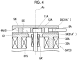
- the back yoke 31A can be configured to include an annular back yoke main body 34 integrally formed with the teeth 32A and a support plate 35 separately provided from the back yoke main body 34.
- the support plate 35 has a disk shape centered on the axis Ac, and a bearing 6' is provided at the center of the support plate 35.
- the configuration described in the first embodiment (the configuration in which the bearing 6 is provided in the end plate 5) and the configuration described in the second embodiment (the configuration in which the bearing 6' is provided in the back yokes 31A and 31B) can be combined. That is, it is possible to adopt a configuration in which the upper bearing 6A is attached to the end plate 5 and the lower bearing 6B is attached to the back yoke 31B, or a configuration in which the upper bearing 6A is attached to the back yoke 31A and the lower bearing 6B is attached to the end plate 5.
- the rotary compressor 100 described in each embodiment is grasped as follows, for example.
- the present disclosure relates to a rotary compressor.
Landscapes
- Engineering & Computer Science (AREA)
- Mechanical Engineering (AREA)
- General Engineering & Computer Science (AREA)
- Applications Or Details Of Rotary Compressors (AREA)
- Connection Of Motors, Electrical Generators, Mechanical Devices, And The Like (AREA)
Abstract
Description
- The present disclosure relates to a rotary compressor.
- This application claims the priority of
Japanese Patent Application No. 2020-065992 filed in Japan on April 1, 2020 - A rotary compressor is known as a device used for compressing a refrigerant in an air conditioner. The rotary compressor includes a motor, a shaft driven by the motor, a rotary piston attached to the shaft, and a cylinder covering the rotary piston. The refrigerant is compressed by an eccentric rotation of the rotary piston in the compression chamber of the cylinder.
- In recent years, as the above-mentioned motor, a type called an axial gap motor has been widely used (for example,
PTL 1 below). An axial gap motor described inPTL 1 has one stator and two rotors facing the stator from both sides in an axial direction. The rotary piston and the cylinder described above are independently disposed below the axial gap motor. - [PTL 1]
Japanese Unexamined Patent Application Publication No. 2008-106694 - However, when the axial gap motor and the cylinder are disposed independently as described above, there are problems that the number of parts increases and a size of the device increases.
- The present disclosure has been made in order to solve the above problems, and an object of the present disclosure is to provide a rotary compressor having a reduced number of parts and a smaller size.
- In order to solve the above problems, according to an aspect of the present disclosure, there is provided a rotary compressor including: a shaft that extends along an axis; a disk-shaped rotor that is fixed to the shaft and centered on the axis; a pair of stators that faces the rotor from both sides in a direction of the axis, and includes a disk-shaped back yoke centered on the axis, teeth protruding from the back yoke, and a coil wound around the teeth; a pair of cylinders that abuts on the stator from the direction of the axis and has an annular shape centered on the axis; a rotary piston that rotates eccentrically with the shaft; a pair of end plates that forms a compression chamber for accommodating the rotary piston together with the back yoke by sandwiching the cylinder together with the stator from the direction of the axis; and a pair of bearings that is provided on at least one of the end plate and the back yoke. Advantageous Effects of Invention
- According to the present disclosure, it is possible to provide a rotary compressor having a reduced number of parts and a smaller size.
-
-
Fig. 1 is a vertical sectional view of a rotary compressor according to a first embodiment of the present disclosure. -
Fig. 2 is an enlarged cross-sectional view of a main part of the rotary compressor according to the first embodiment of the present disclosure. -
Fig. 3 is an enlarged cross-sectional view of a main part of a rotary compressor according to a second embodiment of the present disclosure. -
Fig. 4 is an enlarged cross-sectional view of a main part showing a modification example of the rotary compressor according to the second embodiment of the present disclosure. Description of Embodiments - Hereinafter, a
rotary compressor 100 according to a first embodiment of the present disclosure will be described with reference toFigs. 1 and2 . As shown inFig. 1 , therotary compressor 100 according to the present embodiment includes ashaft 1, arotor 2, astator 3, acylinder 4, anend plate 5, abearing 6, arotary piston 12, and a housing 7 for accommodating these. - The
shaft 1 has a shaftmain body 1H, an uppereccentric shaft 11A, and a lowereccentric shaft 11B. The shaftmain body 1H has a columnar shape extending along an axis Ac. The uppereccentric shaft 11A and the lowereccentric shaft 11B are provided at an interval in a direction of the axis Ac. Each of the uppereccentric shaft 11A and the lowereccentric shaft 11B has a disk shape eccentric in a radial direction with respect to the axis Ac. Eccentric directions of the uppereccentric shaft 11A and the lowereccentric shaft 11B are different from each other. For example, the eccentric direction of the uppereccentric shaft 11A differs from the eccentric direction of the lowereccentric shaft 11B by 180°. - The
rotor 2 is integrally provided at a position (central portion) in a middle of extension of the shaftmain body 1H. That is, therotor 2 is provided at an intermediate position between the uppereccentric shaft 11A and the lowereccentric shaft 11B. Therotor 2 has arotor core 21 and apermanent magnet 22. Therotor core 21 has a disk shape centered on the axis Ac. Thepermanent magnet 22 has a ring shape extending along a peripheral edge of therotor core 21. Instead of thepermanent magnet 22, it is possible to adopt a configuration in which a plurality of magnets are arranged on the peripheral edge of therotor core 21 at intervals in a circumferential direction. - The
stator 3 disposed so as to face therotor 2 from both sides in the direction of the axis Ac includes anupper stator 3A and alower stator 3B. Theupper stator 3A faces therotor 2 from one side (upper side) in the direction of the axis Ac. Theupper stator 3A has aback yoke 31A,teeth 32A, and acoil 33A. Theback yoke 31A has an annular shape centered on the axis Ac. An opening through which theshaft 1 is inserted is formed in a portion including the center of theback yoke 31A. Theteeth 32A are positioned on a surface of theback yoke 31A facing the other side (lower side) in the direction of the axis Ac, and have a rod shape protruding in the direction of the axis Ac from the center position in the radial direction. A plurality ofteeth 32A are arranged at equal intervals in the circumferential direction with respect to the axis Ac. Thecoil 33A is formed by winding a copper wire around each tooth 32A. Power is supplied to thecoil 33A from a power source (not shown). - The
lower stator 3B has aback yoke 31B,teeth 32B, and acoil 33B. Theback yoke 31B has an annular shape centered on the axis Ac. An opening through which theshaft 1 is inserted is formed in a portion including the center of theback yoke 31B. Theteeth 32B are positioned on a surface of theback yoke 31B facing one side (upper side) in the direction of the axis Ac, and have a rod shape protruding in the direction of the axis Ac from the center position in the radial direction. A plurality ofteeth 32B are arranged at equal intervals in the circumferential direction with respect to the axis Ac. Thecoil 33B is formed by winding a copper wire around each tooth 32B. Power is supplied to thecoil 33B from a power source (not shown). As a result, theupper stator 3A and thelower stator 3B are excited, and theshaft 1 is rotated by the electromagnetic force generated between therotor 2 and thestator 3. That is, therotor 2 and thestator 3 constitute a one rotor-two stator type axial gap motor. - The cylinder 4 (
upper cylinder 4A andlower cylinder 4B) abuts on one side (upper side) of theupper stator 3A in the direction of the axis Ac and the other side (lower side) of thelower stator 3B in the direction of the axis Ac. Each of theupper cylinder 4A and thelower cylinder 4B has a cylindrical shape centered on the axis Ac. The above-mentioned uppereccentric shaft 11A and the ring-shaped rotary piston 12 (upperrotary piston 12A) fitted in the uppereccentric shaft 11A are accommodated inside theupper cylinder 4A. The above-mentioned lowereccentric shaft 11B and the ring-shaped rotary piston 12 (lowerrotary piston 12B) fitted in the lowereccentric shaft 11B are accommodated inside thelower cylinder 4B. Further,intake ports upper cylinder 4A and thelower cylinder 4B in the circumferential direction, respectively. - The end plates 5 (
upper end plate 5A,lower end plate 5B) abut on one side (upper side) of theupper cylinder 4A in the direction of the axis Ac and the other side (lower side) of thelower cylinder 4B in the direction of the axis Ac, respectively. That is, theupper end plate 5A sandwiches theupper cylinder 4A together with theback yoke 31A from the direction of the axis Ac. Similarly, thelower end plate 5B sandwiches thelower cylinder 4B together with theback yoke 31B from the direction of the axis Ac. Each of theupper end plate 5A and thelower end plate 5B has a disk shape centered on the axis Ac. The bearings 6 (upper bearing 6A,lower bearing 6B) are attached to a portion including the centers of theupper end plate 5A and thelower end plate 5B, respectively. A shaft end of the shaftmain body 1H is supported by thesebearings 6. Further, theupper end plate 5A and thelower end plate 5B are fixed to an inner peripheral surface of the housing 7 in a tightly fitted state. - As shown in an enlarged manner in
Fig. 2 , a surface of theupper end plate 5A facing the other side (lower side) in the direction of the axis Ac is an end platemain surface 5S. Further, a surface of theback yoke 31A facing one side (upper side) of the direction of the axis Ac is a backyoke facing surface 31S. An upper compression chamber C1 is formed by the end platemain surface 5S, the backyoke facing surface 31S, and the inner peripheral surface of theupper cylinder 4A. That is, in the present embodiment, a portion (backyoke 31A) of thestator 3 also serves as a member forming a portion of the upper compression chamber C1. Further, a lower compression chamber C2 is also formed by theback yoke 31B of thelower stator 3B, thelower end plate 5B, and thelower cylinder 4B, similarly to the upper compression chamber C1. - In the upper compression chamber C1 and the lower compression chamber C2, the above-mentioned
upper rotary piston 12A andlower rotary piston 12B rotate eccentrically, respectively. As a result, volumes of the upper compression chamber C1 and the lower compression chamber C2 change with time, and the refrigerant taken in from theintake ports discharge port 7A. - It is also possible to adopt a configuration in which the pressure of the refrigerant is increased in two stages by sequentially passing the upper compression chamber C1 and the lower compression chamber C2, and it is also possible to adopt a configuration in which the upper compression chamber C1 and the lower compression chamber C2 function independently.
- According to the above configuration, the back yokes 31A and 31B of the
stator 3 form the compression chambers C1 and C2 together with theend plate 5 and thecylinder 4. In other words, the back yokes 31A and 31B have both a function as a portion of the motor and a function as a portion of the members forming the compression chambers C1 and C2. As a result, the number of parts can be reduced. Further, the size of the device in the direction of the axis Ac can be suppressed by the reduced members. - Further, according to the above configuration, since the
bearing 6 is provided in each of the pair ofend plates 5, theshaft 1 can be supported by both end portions thereof. As a result, noise and vibration are reduced, and theshaft 1 can be rotated more stably. - Next, a second embodiment of the present disclosure will be described with reference to
Fig. 3 . The same components as those in the first embodiment are designated by the same reference numerals, and detailed description thereof will be omitted. As shown inFig. 3 , in the present embodiment, a bearing 6' (upper bearing 6A') is integrally provided in aback yoke 31A instead of an end plate 5' (upper end plate 5A'). As a result, the end plate 5' has a disk shape centered on an axis Ac, and no opening or the like is formed in the portion including the center. Further, although not shown in detail, another bearing 6' located at the lower portion is also integrally provided on aback yoke 31B like theupper bearing 6A'. - According to the above configuration, since the bearing 6' is provided in each of the pair of
back yokes shaft 1 does not protrude from the end plate 5' side. That is, the dimension of theshaft 1 in the direction of the axis Ac can be kept small. As a result, the possibility that theshaft 1 is bent or misaligned can be further reduced. As a result, arotary compressor 100 can be operated more stably. - The embodiments of the present disclosure have been described above. It is possible to make various changes and modifications to the above configuration as long as it does not deviate from the gist of the present disclosure. For example, as a modification example of the second embodiment, as shown in
Fig. 4 , theback yoke 31A can be configured to include an annular back yokemain body 34 integrally formed with theteeth 32A and asupport plate 35 separately provided from the back yokemain body 34. Thesupport plate 35 has a disk shape centered on the axis Ac, and a bearing 6' is provided at the center of thesupport plate 35. According to such a configuration, when thecoil 33A is configured, the back yokemain body 34 is detachable from thesupport plate 35, and thus, ease of manufacturing can be further improved. - Further, the configuration described in the first embodiment (the configuration in which the
bearing 6 is provided in the end plate 5) and the configuration described in the second embodiment (the configuration in which the bearing 6' is provided in theback yokes upper bearing 6A is attached to theend plate 5 and thelower bearing 6B is attached to theback yoke 31B, or a configuration in which theupper bearing 6A is attached to theback yoke 31A and thelower bearing 6B is attached to theend plate 5. - The
rotary compressor 100 described in each embodiment is grasped as follows, for example. - (1) A
rotary compressor 100 according to a first aspect includes ashaft 1 that extends along an axis Ac, a disk-shapedrotor 2 that is fixed to theshaft 1 and centered on the axis Ac, a pair ofstators 3 that faces therotor 2 from both sides in a direction of the axis Ac, and includes disk-shaped back yokes 31A and 31B centered on the axis Ac,teeth back yokes teeth cylinders 4 that abuts on thestator 3 from the direction of the axis Ac and has an annular shape centered on the axis Ac, a pair ofrotary pistons 12 that rotates eccentrically with theshaft 1, a pair ofend plates 5 that forms compression chambers C1 and C2 for accommodating therotary piston 12 together with theback yokes cylinder 4 together with thestator 3 from the direction of the axis Ac, and a pair ofbearings 6 that is provided on at least one of theend plate 5 and theback yokes
According to the above configuration, the back yokes 31A and 31B of thestator 3 form the compression chambers C1 and C2 together with theend plate 5 and thecylinder 4. In other words, the back yokes 31A and 31B have both a function as a portion of the motor and a function as a portion of the members forming the compression chambers C1 and C2. As a result, the number of parts can be reduced. Further, the size of the device in the direction of the axis Ac can be suppressed by the reduced members. - (2) In the
rotary compressor 100 according to a second aspect, thebearing 6 may be integrally provided in each of the pair ofend plates 5.
According to the above configuration, since thebearing 6 is provided in each of the pair ofend plates 5, theshaft 1 can be supported by both end portions thereof. As a result, noise and vibration are reduced, and theshaft 1 can be rotated more stably. - (3) In the
rotary compressor 100 according to a third aspect, thebearing 6 may be integrally provided in each of the pair ofback yokes
According to the above configuration, since thebearing 6 is provided in each of the pair ofback yokes shaft 1 does not protrude from theend plate 5 side. That is, the dimension of theshaft 1 can be kept small. This makes it possible to reduce the possibility that theshaft 1 is bent or misaligned. - (4) In the
rotary compressor 100 according to a fourth aspect, thebearing 6 may protrude from theback yokes rotor 2.
According to the above configuration, since thebearing 6 protrudes from theback yokes rotor 2, it is possible to secure a large dimension of thebearing 6 in the direction of the axis Ac. This makes it possible to stably support theshaft 1 even when the load is high. - The present disclosure relates to a rotary compressor.
- According to the present disclosure, it is possible to provide a rotary compressor having a reduced number of parts and a smaller size.
-
- 100 Rotary compressor
- 1 Shaft
- 1H Shaft main body
- 11A Upper eccentric shaft
- 11B Lower eccentric shaft
- 12 Rotary piston
- 12A Upper rotary piston
- 12B Lower rotary piston
- 2 Rotor
- 21 Rotor core
- 22 Permanent magnet
- 3 Stator
- 3A Upper stator
- 3B Lower stator
- 31A, 31B Back yoke
- 31S Back yoke facing surface
- 32A, 32B Teeth
- 33A, 33B Coil
- 4 Cylinder
- 4A Upper cylinder
- 4B Lower cylinder
- 5 End plate
- 5A Upper end plate
- 5B Lower end plate
- 5S End plate main surface
- 6 Bearing
- 6A Upper bearing
- 6B Lower bearing
- 7 Housing
- 7A Discharge port
- 8A, 8B Intake port
- Ac Axis
- C1 Upper compression chamber
- C2 Lower compression chamber
Claims (4)
- A rotary compressor comprising:
a shaft that extends along an axis;a disk-shaped rotor that is fixed to the shaft and centered on the axis;a pair of stators that faces the rotor from both sides in a direction of the axis, and includes a disk-shaped back yoke centered on the axis, teeth protruding from the back yoke, and a coil wound around the teeth;a pair of cylinders that abuts on the stator from the direction of the axis and has an annular shape centered on the axis;a rotary piston that rotates eccentrically with the shaft;a pair of end plates that forms a compression chamber for accommodating the rotary piston together with the back yoke by sandwiching the cylinder together with the stator from the direction of the axis; anda pair of bearings that is provided on at least one of the end plate and the back yoke. - The rotary compressor according to claim 1,
wherein the bearing is integrally provided in each of the pair of end plates. - The rotary compressor according to claim 1 or 2,
wherein the bearing is integrally provided in each of the pair of back yokes. - The rotary compressor according to claim 3,
wherein the bearing protrudes from the back yoke in a direction toward the rotor.
Applications Claiming Priority (2)
| Application Number | Priority Date | Filing Date | Title |
|---|---|---|---|
| JP2020065992A JP7381386B2 (en) | 2020-04-01 | 2020-04-01 | rotary compressor |
| PCT/JP2021/014156 WO2021201223A1 (en) | 2020-04-01 | 2021-04-01 | Rotary compressor |
Publications (4)
| Publication Number | Publication Date |
|---|---|
| EP4130478A1 true EP4130478A1 (en) | 2023-02-08 |
| EP4130478A4 EP4130478A4 (en) | 2023-08-30 |
| EP4130478B1 EP4130478B1 (en) | 2025-05-28 |
| EP4130478C0 EP4130478C0 (en) | 2025-05-28 |
Family
ID=77927326
Family Applications (1)
| Application Number | Title | Priority Date | Filing Date |
|---|---|---|---|
| EP21781413.6A Active EP4130478B1 (en) | 2020-04-01 | 2021-04-01 | Rotary compressor |
Country Status (3)
| Country | Link |
|---|---|
| EP (1) | EP4130478B1 (en) |
| JP (1) | JP7381386B2 (en) |
| WO (1) | WO2021201223A1 (en) |
Family Cites Families (10)
| Publication number | Priority date | Publication date | Assignee | Title |
|---|---|---|---|---|
| JPS6469793A (en) * | 1987-09-11 | 1989-03-15 | Hitachi Ltd | Enclosed type motor-driven compressor |
| US20060153705A1 (en) | 2004-11-10 | 2006-07-13 | Horton W T | Drive shaft for compressor |
| EP1850451A4 (en) | 2005-01-19 | 2014-01-22 | Daikin Ind Ltd | ROTOR, AXIAL INTERLOCKING MOTOR, MOTOR DRIVING METHOD, AND COMPRESSOR |
| JP4816358B2 (en) * | 2006-09-19 | 2011-11-16 | ダイキン工業株式会社 | Motor and compressor |
| JP4835384B2 (en) | 2006-10-26 | 2011-12-14 | ダイキン工業株式会社 | Compressor |
| JP5963436B2 (en) | 2011-12-21 | 2016-08-03 | 株式会社ヴァレオジャパン | Electric compressor |
| JP6001356B2 (en) * | 2012-06-29 | 2016-10-05 | 株式会社ヴァレオジャパン | Electric compressor |
| CN104638866A (en) | 2013-11-15 | 2015-05-20 | 珠海格力节能环保制冷技术研究中心有限公司 | Motor and compressor with same |
| CN104564685A (en) | 2015-01-06 | 2015-04-29 | 广东美芝制冷设备有限公司 | Rotary compressor and refrigerating device provided with same |
| JP2020065992A (en) | 2018-10-26 | 2020-04-30 | 臼井国際産業株式会社 | Gas dissolution device and algae culturing device |
-
2020
- 2020-04-01 JP JP2020065992A patent/JP7381386B2/en active Active
-
2021
- 2021-04-01 EP EP21781413.6A patent/EP4130478B1/en active Active
- 2021-04-01 WO PCT/JP2021/014156 patent/WO2021201223A1/en not_active Ceased
Also Published As
| Publication number | Publication date |
|---|---|
| JP7381386B2 (en) | 2023-11-15 |
| EP4130478B1 (en) | 2025-05-28 |
| EP4130478C0 (en) | 2025-05-28 |
| EP4130478A4 (en) | 2023-08-30 |
| JP2021161989A (en) | 2021-10-11 |
| WO2021201223A1 (en) | 2021-10-07 |
Similar Documents
| Publication | Publication Date | Title |
|---|---|---|
| US9641032B2 (en) | Motor having magnets embedded in a rotor and electric compressor using same | |
| EP2750263A2 (en) | Permanent magnet embedded type rotating electrical machine | |
| CN102113196B (en) | Stator, motor and compressor | |
| JP5478461B2 (en) | Electric motor and compressor | |
| JP6680779B2 (en) | Compressor and refrigeration cycle device | |
| KR102491657B1 (en) | Electric motor and compressor having the same | |
| US10298089B2 (en) | Electric compressor | |
| CN210297519U (en) | Moving core type reciprocating motor and reciprocating compressor with moving core type reciprocating motor | |
| CN111490661B (en) | Compressor provided with motor | |
| EP4130478B1 (en) | Rotary compressor | |
| KR102172260B1 (en) | Motor and compressor having thereof | |
| AU2018306257B2 (en) | Compressor | |
| JP2010041852A (en) | Stator, motor and compressor | |
| KR101139086B1 (en) | Compressor | |
| JP5061576B2 (en) | Axial gap type motor and compressor using the same | |
| JPWO2020208777A1 (en) | Compressor and motor for compressor | |
| JP5871469B2 (en) | Electric motor and electric compressor using the same | |
| WO2023139637A1 (en) | Rotary compressor | |
| EP3550700B1 (en) | Stator, motor and compressor | |
| KR20180119051A (en) | Motor and compressor having this | |
| CN113195893A (en) | Motor for electric compressor, electric compressor including the same, and method for manufacturing motor for electric compressor | |
| CN113472168B (en) | Motor | |
| JP2012139045A (en) | Rotor, motor, and compressor | |
| JP2026031007A (en) | Motor | |
| KR20250150993A (en) | Stator and electric compressor including the same |
Legal Events
| Date | Code | Title | Description |
|---|---|---|---|
| STAA | Information on the status of an ep patent application or granted ep patent |
Free format text: STATUS: THE INTERNATIONAL PUBLICATION HAS BEEN MADE |
|
| PUAI | Public reference made under article 153(3) epc to a published international application that has entered the european phase |
Free format text: ORIGINAL CODE: 0009012 |
|
| STAA | Information on the status of an ep patent application or granted ep patent |
Free format text: STATUS: REQUEST FOR EXAMINATION WAS MADE |
|
| 17P | Request for examination filed |
Effective date: 20220928 |
|
| AK | Designated contracting states |
Kind code of ref document: A1 Designated state(s): AL AT BE BG CH CY CZ DE DK EE ES FI FR GB GR HR HU IE IS IT LI LT LU LV MC MK MT NL NO PL PT RO RS SE SI SK SM TR |
|
| DAV | Request for validation of the european patent (deleted) | ||
| DAX | Request for extension of the european patent (deleted) | ||
| A4 | Supplementary search report drawn up and despatched |
Effective date: 20230728 |
|
| RIC1 | Information provided on ipc code assigned before grant |
Ipc: F04C 29/00 20060101ALI20230724BHEP Ipc: F04C 23/02 20060101AFI20230724BHEP |
|
| GRAP | Despatch of communication of intention to grant a patent |
Free format text: ORIGINAL CODE: EPIDOSNIGR1 |
|
| STAA | Information on the status of an ep patent application or granted ep patent |
Free format text: STATUS: GRANT OF PATENT IS INTENDED |
|
| INTG | Intention to grant announced |
Effective date: 20241122 |
|
| GRAS | Grant fee paid |
Free format text: ORIGINAL CODE: EPIDOSNIGR3 |
|
| GRAA | (expected) grant |
Free format text: ORIGINAL CODE: 0009210 |
|
| STAA | Information on the status of an ep patent application or granted ep patent |
Free format text: STATUS: THE PATENT HAS BEEN GRANTED |
|
| AK | Designated contracting states |
Kind code of ref document: B1 Designated state(s): AL AT BE BG CH CY CZ DE DK EE ES FI FR GB GR HR HU IE IS IT LI LT LU LV MC MK MT NL NO PL PT RO RS SE SI SK SM TR |
|
| REG | Reference to a national code |
Ref country code: GB Ref legal event code: FG4D |
|
| REG | Reference to a national code |
Ref country code: CH Ref legal event code: EP |
|
| REG | Reference to a national code |
Ref country code: DE Ref legal event code: R096 Ref document number: 602021031463 Country of ref document: DE |
|
| REG | Reference to a national code |
Ref country code: IE Ref legal event code: FG4D |
|
| U01 | Request for unitary effect filed |
Effective date: 20250528 |
|
| U07 | Unitary effect registered |
Designated state(s): AT BE BG DE DK EE FI FR IT LT LU LV MT NL PT RO SE SI Effective date: 20250605 |
|
| PG25 | Lapsed in a contracting state [announced via postgrant information from national office to epo] |
Ref country code: ES Free format text: LAPSE BECAUSE OF FAILURE TO SUBMIT A TRANSLATION OF THE DESCRIPTION OR TO PAY THE FEE WITHIN THE PRESCRIBED TIME-LIMIT Effective date: 20250528 |
|
| PG25 | Lapsed in a contracting state [announced via postgrant information from national office to epo] |
Ref country code: NO Free format text: LAPSE BECAUSE OF FAILURE TO SUBMIT A TRANSLATION OF THE DESCRIPTION OR TO PAY THE FEE WITHIN THE PRESCRIBED TIME-LIMIT Effective date: 20250828 Ref country code: GR Free format text: LAPSE BECAUSE OF FAILURE TO SUBMIT A TRANSLATION OF THE DESCRIPTION OR TO PAY THE FEE WITHIN THE PRESCRIBED TIME-LIMIT Effective date: 20250829 |
|
| PG25 | Lapsed in a contracting state [announced via postgrant information from national office to epo] |
Ref country code: PL Free format text: LAPSE BECAUSE OF FAILURE TO SUBMIT A TRANSLATION OF THE DESCRIPTION OR TO PAY THE FEE WITHIN THE PRESCRIBED TIME-LIMIT Effective date: 20250528 |
|
| PG25 | Lapsed in a contracting state [announced via postgrant information from national office to epo] |
Ref country code: HR Free format text: LAPSE BECAUSE OF FAILURE TO SUBMIT A TRANSLATION OF THE DESCRIPTION OR TO PAY THE FEE WITHIN THE PRESCRIBED TIME-LIMIT Effective date: 20250528 |
|
| PG25 | Lapsed in a contracting state [announced via postgrant information from national office to epo] |
Ref country code: RS Free format text: LAPSE BECAUSE OF FAILURE TO SUBMIT A TRANSLATION OF THE DESCRIPTION OR TO PAY THE FEE WITHIN THE PRESCRIBED TIME-LIMIT Effective date: 20250828 |
|
| PG25 | Lapsed in a contracting state [announced via postgrant information from national office to epo] |
Ref country code: IS Free format text: LAPSE BECAUSE OF FAILURE TO SUBMIT A TRANSLATION OF THE DESCRIPTION OR TO PAY THE FEE WITHIN THE PRESCRIBED TIME-LIMIT Effective date: 20250928 |
|
| PG25 | Lapsed in a contracting state [announced via postgrant information from national office to epo] |
Ref country code: SM Free format text: LAPSE BECAUSE OF FAILURE TO SUBMIT A TRANSLATION OF THE DESCRIPTION OR TO PAY THE FEE WITHIN THE PRESCRIBED TIME-LIMIT Effective date: 20250528 |
|
| PG25 | Lapsed in a contracting state [announced via postgrant information from national office to epo] |
Ref country code: CZ Free format text: LAPSE BECAUSE OF FAILURE TO SUBMIT A TRANSLATION OF THE DESCRIPTION OR TO PAY THE FEE WITHIN THE PRESCRIBED TIME-LIMIT Effective date: 20250528 |
|
| PG25 | Lapsed in a contracting state [announced via postgrant information from national office to epo] |
Ref country code: SK Free format text: LAPSE BECAUSE OF FAILURE TO SUBMIT A TRANSLATION OF THE DESCRIPTION OR TO PAY THE FEE WITHIN THE PRESCRIBED TIME-LIMIT Effective date: 20250528 |
|
| PLBE | No opposition filed within time limit |
Free format text: ORIGINAL CODE: 0009261 |
|
| STAA | Information on the status of an ep patent application or granted ep patent |
Free format text: STATUS: NO OPPOSITION FILED WITHIN TIME LIMIT |
|
| PGFP | Annual fee paid to national office [announced via postgrant information from national office to epo] |
Ref country code: GB Payment date: 20260313 Year of fee payment: 6 |
|
| REG | Reference to a national code |
Ref country code: CH Ref legal event code: L10 Free format text: ST27 STATUS EVENT CODE: U-0-0-L10-L00 (AS PROVIDED BY THE NATIONAL OFFICE) Effective date: 20260409 |
|
| U20 | Renewal fee for the european patent with unitary effect paid |
Year of fee payment: 6 Effective date: 20260310 |
|
| 26N | No opposition filed |
Effective date: 20260303 |