EP4130476A1 - Fluid transfer pump - Google Patents
Fluid transfer pump Download PDFInfo
- Publication number
- EP4130476A1 EP4130476A1 EP22185422.7A EP22185422A EP4130476A1 EP 4130476 A1 EP4130476 A1 EP 4130476A1 EP 22185422 A EP22185422 A EP 22185422A EP 4130476 A1 EP4130476 A1 EP 4130476A1
- Authority
- EP
- European Patent Office
- Prior art keywords
- electric motor
- fluid transfer
- transfer pump
- ring gear
- power supply
- Prior art date
- Legal status (The legal status is an assumption and is not a legal conclusion. Google has not performed a legal analysis and makes no representation as to the accuracy of the status listed.)
- Granted
Links
Images





Classifications
-
- F—MECHANICAL ENGINEERING; LIGHTING; HEATING; WEAPONS; BLASTING
- F04—POSITIVE - DISPLACEMENT MACHINES FOR LIQUIDS; PUMPS FOR LIQUIDS OR ELASTIC FLUIDS
- F04C—ROTARY-PISTON, OR OSCILLATING-PISTON, POSITIVE-DISPLACEMENT MACHINES FOR LIQUIDS; ROTARY-PISTON, OR OSCILLATING-PISTON, POSITIVE-DISPLACEMENT PUMPS
- F04C5/00—Rotary-piston machines or pumps with the working-chamber walls at least partly resiliently deformable
-
- F—MECHANICAL ENGINEERING; LIGHTING; HEATING; WEAPONS; BLASTING
- F04—POSITIVE - DISPLACEMENT MACHINES FOR LIQUIDS; PUMPS FOR LIQUIDS OR ELASTIC FLUIDS
- F04D—NON-POSITIVE-DISPLACEMENT PUMPS
- F04D13/00—Pumping installations or systems
- F04D13/02—Units comprising pumps and their driving means
- F04D13/06—Units comprising pumps and their driving means the pump being electrically driven
- F04D13/068—Battery powered
-
- F—MECHANICAL ENGINEERING; LIGHTING; HEATING; WEAPONS; BLASTING
- F04—POSITIVE - DISPLACEMENT MACHINES FOR LIQUIDS; PUMPS FOR LIQUIDS OR ELASTIC FLUIDS
- F04B—POSITIVE-DISPLACEMENT MACHINES FOR LIQUIDS; PUMPS
- F04B17/00—Pumps characterised by combination with, or adaptation to, specific driving engines or motors
- F04B17/03—Pumps characterised by combination with, or adaptation to, specific driving engines or motors driven by electric motors
-
- F—MECHANICAL ENGINEERING; LIGHTING; HEATING; WEAPONS; BLASTING
- F04—POSITIVE - DISPLACEMENT MACHINES FOR LIQUIDS; PUMPS FOR LIQUIDS OR ELASTIC FLUIDS
- F04B—POSITIVE-DISPLACEMENT MACHINES FOR LIQUIDS; PUMPS
- F04B35/00—Piston pumps specially adapted for elastic fluids and characterised by the driving means to their working members, or by combination with, or adaptation to, specific driving engines or motors, not otherwise provided for
- F04B35/04—Piston pumps specially adapted for elastic fluids and characterised by the driving means to their working members, or by combination with, or adaptation to, specific driving engines or motors, not otherwise provided for the means being electric
-
- F—MECHANICAL ENGINEERING; LIGHTING; HEATING; WEAPONS; BLASTING
- F04—POSITIVE - DISPLACEMENT MACHINES FOR LIQUIDS; PUMPS FOR LIQUIDS OR ELASTIC FLUIDS
- F04B—POSITIVE-DISPLACEMENT MACHINES FOR LIQUIDS; PUMPS
- F04B35/00—Piston pumps specially adapted for elastic fluids and characterised by the driving means to their working members, or by combination with, or adaptation to, specific driving engines or motors, not otherwise provided for
- F04B35/06—Mobile combinations
-
- F—MECHANICAL ENGINEERING; LIGHTING; HEATING; WEAPONS; BLASTING
- F04—POSITIVE - DISPLACEMENT MACHINES FOR LIQUIDS; PUMPS FOR LIQUIDS OR ELASTIC FLUIDS
- F04B—POSITIVE-DISPLACEMENT MACHINES FOR LIQUIDS; PUMPS
- F04B39/00—Component parts, details, or accessories, of pumps or pumping systems specially adapted for elastic fluids, not otherwise provided for in, or of interest apart from, groups F04B25/00 - F04B37/00
- F04B39/12—Casings; Cylinders; Cylinder heads; Fluid connections
- F04B39/121—Casings
-
- F—MECHANICAL ENGINEERING; LIGHTING; HEATING; WEAPONS; BLASTING
- F04—POSITIVE - DISPLACEMENT MACHINES FOR LIQUIDS; PUMPS FOR LIQUIDS OR ELASTIC FLUIDS
- F04B—POSITIVE-DISPLACEMENT MACHINES FOR LIQUIDS; PUMPS
- F04B49/00—Control, e.g. of pump delivery, or pump pressure of, or safety measures for, machines, pumps, or pumping installations, not otherwise provided for, or of interest apart from, groups F04B1/00 - F04B47/00
- F04B49/06—Control using electricity
-
- F—MECHANICAL ENGINEERING; LIGHTING; HEATING; WEAPONS; BLASTING
- F04—POSITIVE - DISPLACEMENT MACHINES FOR LIQUIDS; PUMPS FOR LIQUIDS OR ELASTIC FLUIDS
- F04C—ROTARY-PISTON, OR OSCILLATING-PISTON, POSITIVE-DISPLACEMENT MACHINES FOR LIQUIDS; ROTARY-PISTON, OR OSCILLATING-PISTON, POSITIVE-DISPLACEMENT PUMPS
- F04C11/00—Combinations of two or more machines or pumps, each being of rotary-piston or oscillating-piston type; Pumping installations
- F04C11/008—Enclosed motor pump units
-
- F—MECHANICAL ENGINEERING; LIGHTING; HEATING; WEAPONS; BLASTING
- F04—POSITIVE - DISPLACEMENT MACHINES FOR LIQUIDS; PUMPS FOR LIQUIDS OR ELASTIC FLUIDS
- F04C—ROTARY-PISTON, OR OSCILLATING-PISTON, POSITIVE-DISPLACEMENT MACHINES FOR LIQUIDS; ROTARY-PISTON, OR OSCILLATING-PISTON, POSITIVE-DISPLACEMENT PUMPS
- F04C14/00—Control of, monitoring of, or safety arrangements for, machines, pumps or pumping installations
- F04C14/08—Control of, monitoring of, or safety arrangements for, machines, pumps or pumping installations characterised by varying the rotational speed
-
- F—MECHANICAL ENGINEERING; LIGHTING; HEATING; WEAPONS; BLASTING
- F04—POSITIVE - DISPLACEMENT MACHINES FOR LIQUIDS; PUMPS FOR LIQUIDS OR ELASTIC FLUIDS
- F04C—ROTARY-PISTON, OR OSCILLATING-PISTON, POSITIVE-DISPLACEMENT MACHINES FOR LIQUIDS; ROTARY-PISTON, OR OSCILLATING-PISTON, POSITIVE-DISPLACEMENT PUMPS
- F04C15/00—Component parts, details or accessories of machines, pumps or pumping installations, not provided for in groups F04C2/00 - F04C14/00
-
- F—MECHANICAL ENGINEERING; LIGHTING; HEATING; WEAPONS; BLASTING
- F04—POSITIVE - DISPLACEMENT MACHINES FOR LIQUIDS; PUMPS FOR LIQUIDS OR ELASTIC FLUIDS
- F04C—ROTARY-PISTON, OR OSCILLATING-PISTON, POSITIVE-DISPLACEMENT MACHINES FOR LIQUIDS; ROTARY-PISTON, OR OSCILLATING-PISTON, POSITIVE-DISPLACEMENT PUMPS
- F04C15/00—Component parts, details or accessories of machines, pumps or pumping installations, not provided for in groups F04C2/00 - F04C14/00
- F04C15/0057—Driving elements, brakes, couplings, transmission specially adapted for machines or pumps
- F04C15/0061—Means for transmitting movement from the prime mover to driven parts of the pump, e.g. clutches, couplings, transmissions
-
- F—MECHANICAL ENGINEERING; LIGHTING; HEATING; WEAPONS; BLASTING
- F04—POSITIVE - DISPLACEMENT MACHINES FOR LIQUIDS; PUMPS FOR LIQUIDS OR ELASTIC FLUIDS
- F04D—NON-POSITIVE-DISPLACEMENT PUMPS
- F04D13/00—Pumping installations or systems
- F04D13/02—Units comprising pumps and their driving means
- F04D13/06—Units comprising pumps and their driving means the pump being electrically driven
-
- F—MECHANICAL ENGINEERING; LIGHTING; HEATING; WEAPONS; BLASTING
- F04—POSITIVE - DISPLACEMENT MACHINES FOR LIQUIDS; PUMPS FOR LIQUIDS OR ELASTIC FLUIDS
- F04C—ROTARY-PISTON, OR OSCILLATING-PISTON, POSITIVE-DISPLACEMENT MACHINES FOR LIQUIDS; ROTARY-PISTON, OR OSCILLATING-PISTON, POSITIVE-DISPLACEMENT PUMPS
- F04C2240/00—Components
- F04C2240/30—Casings or housings
-
- F—MECHANICAL ENGINEERING; LIGHTING; HEATING; WEAPONS; BLASTING
- F04—POSITIVE - DISPLACEMENT MACHINES FOR LIQUIDS; PUMPS FOR LIQUIDS OR ELASTIC FLUIDS
- F04C—ROTARY-PISTON, OR OSCILLATING-PISTON, POSITIVE-DISPLACEMENT MACHINES FOR LIQUIDS; ROTARY-PISTON, OR OSCILLATING-PISTON, POSITIVE-DISPLACEMENT PUMPS
- F04C2240/00—Components
- F04C2240/40—Electric motor
Definitions
- the present utility model relates to a fluid transfer pump, in particular to a portable fluid transfer pump driven by an electric motor.
- a fluid transfer pump driven by an electric motor transfers water or other fluids from one position to another by means of a pump unit.
- An inlet of the pump can be connected to a fluid source such as a water pool via an input pipe.
- An outlet of the pump can be connected to a discharge pipe such as a standard garden hose to transfer a discharged fluid to a desired position.
- a type of fluid transfer pump performs the suction and discharge of the fluid by the rotation of an impeller.
- the fluid transfer pump is typically connected to a power supply through an electric wire.
- a battery-powered fluid transfer pump is emerging.
- the battery-powered fluid transfer pump is popular with users due to its portability.
- this cordless pump has some shortcomings, such as a large size, a heavy weight, a complex structure, a short battery life, and a low heat dissipation efficiency of the electric motor.
- the present utility model provides a fluid transfer pump.
- the fluid transfer pump comprises: a housing, a pump unit, an electric motor assembly, a power supply mounting base, and a speed change mechanism, wherein the pump unit comprises an impeller; the electric motor assembly is used to drive the impeller to rotate around an axis of the impeller; the power supply mounting base is used to receive a power supply for supplying electricity to the pump unit; and the speed change mechanism is arranged between the pump unit and the electric motor assembly.
- the power supply mounting base is arranged in a power supply compartment; the pump unit, the speed change mechanism, the electric motor assembly, and the power supply compartment are successively arrayed in an extension direction of the axis of the impeller; and the power supply can be guided into the power supply compartment in a mounting direction.
- an axis in the mounting direction is inclined at an angle relative to the axis of the impeller.
- the speed change mechanism can be used to reduce an output rotation speed of the electric motor assembly.
- the speed change mechanism can comprise a gearbox shell as well as a gear and a ring gear which are meshed with each other and accommodated in the gearbox shell; and the gear is in drive connection with an output shaft of the electric motor assembly, and the ring gear is in drive connection with a drive shaft of the impeller.
- the ring gear comprises a main ring gear body on which inner teeth are formed as well as a ring gear extension part extending axially from the main ring gear body, and the ring gear extension part matches the drive shaft of the impeller.
- a first bearing can be disposed around the ring gear extension part.
- the ring gear can comprise a ring gear shaft which defines a rotational axis of the ring gear; a bearing seat is formed in the ring gear; and a second bearing disposed around the ring gear shaft is accommodated in the bearing seat.
- the ring gear can comprise a transition part connecting the main ring gear body to the ring gear extension part, and at least one part of the bearing seat is formed in the transition part.
- the gearbox shell can be fixed to a mounting flange located at one end of the housing of the pump unit.
- the power supply compartment can comprise a compartment shell and a cover pivotally connected to the compartment shell; the cover has a first sealing edge, and the compartment shell has a second sealing edge aligned to the first sealing edge; and a groove used to accommodate at least one part of a sealing component is formed in at least one of the first sealing edge and the second sealing edge.
- at least one of the first sealing edge and the second sealing edge has a ridge part extending outward; and when the cover is in a closed position, the ridge part abuts against the sealing component.
- the fluid transfer pump can comprise a locking component used to lock the cover in the closed position; the locking component is able to move between a locked position and an unlocked position; and when the locking component is in the locked position, at least one part of the locking component presses against the first sealing edge of the cover.
- the compartment shell comprises a protrusion part extending from the second sealing edge, the locking component is held on the protrusion part through a biasing component, and the biasing component applies a biasing force to the locking component to resist movement of the locking component away from the protrusion part.
- an internal space of the housing can be divided into a plurality of areas by at least one separator; the electric motor assembly comprises an electric motor, and a fan driven by the electric motor and adjacent to one end of the electric motor; and the fan and the other end of the electric motor are respectively located in different areas.
- the fan is located in a first area, the first area is at least partially defined by a first wall part of the housing, and a first opening is formed in the first wall part such that the first area communicates with an external environment.
- the first opening is radially aligned to the fan.
- the other end of the electric motor is located in a second area, the second area is at least partially defined by a second wall part of the housing, and a second opening is formed in the second wall part such that the second area communicates with the external environment.
- the second opening is located above the electric motor.
- the first area and the second area are separated by a first partition plate extending from an inner wall of the housing, and the first partition plate is in a close fit with a first sealing ring disposed around the electric motor assembly.
- the pump unit is located in a third area, and the third area and the first area are separated by a second partition plate extending from the inner wall of the housing.
- the second partition plate is in a close fit with the second sealing ring disposed around the gearbox shell.
- the fluid transfer pump can comprise a base; the base has support parts and an elevation part elevated relative to bottom surfaces of the support parts; and a hole via which an internal space of the housing communicates with the external environment is formed in at least one of the support parts and the elevation part.
- the elevation part is located below the electric motor assembly, the elevation part comprises a bottom wall and a baffle plate located on an inner side of the bottom wall, the hole is formed in the bottom wall, and a tortuous path from the hole to the internal space of the housing is defined by the baffle plate.
- FIG. 1 shows a fluid transfer pump, which is used to pump a fluid such as water, according to an embodiment of the present utility model.
- the fluid transfer pump comprises a housing 100 and a pump unit 200 accommodated in the housing 100.
- the pump unit comprises a fluid inlet 201 used to be connected to an input pipe and a fluid outlet 202 used to be connected to a discharge pipe.
- the pump unit 200 is arranged at a front part (a left side in FIG. 1 ) of the housing 100, and the fluid inlet 201 and the fluid outlet 202 respectively extend from two sides of the housing 100.
- the pump unit 200 may be arranged at other positions in the housing.
- the fluid inlet 201 and the fluid outlet 202 may be arranged in an upper side, a front end, or a rear end of the housing.
- a base 180 stably supports the fluid transfer pump on the ground or other supporting surfaces.
- the base 180 can be integrated with the housing 100 or be independent of the housing.
- the fluid transfer pump shown in FIG. 1 can be powered by a portable power supply.
- the portable power supply can be a lithium battery and is removably mounted on the fluid transfer pump.
- the fluid transfer pump comprises a power supply compartment 500 located at a rear part (a right side in FIG. 1 ) of the housing 100, and a power supply for supplying electricity to the pump unit 200 is accommodated in the power supply compartment 500.
- the fluid transfer pump further comprises a handle 110 for a user to grasp.
- the handle 110 can be located above the housing 100 and connected to the front part and rear part of the housing 100. As shown in FIG. 1 , one end of the handle 110 is adjacent to the fluid inlet 201 and the fluid outlet 202, and the other end of the handle is adjacent to the power supply compartment 500.
- the handle 110 can be integrated with the housing 100 or be mounted on the housing 100 as an independent component.
- the handle 110 comprises a grasping part, the size and contour of which conform to a palm of the user.
- the grasping part can be covered with an elastic material such as rubber, which is deformable when the grasping part is grasped by the user, so as to improve grasping comfort.
- At least one part of the grasping part can be covered with pits or ridges to prevent the handle from slipping out of a hand of the user.
- the grasping part of the handle 110 intersects a vertical line passing through the center of gravity of the whole fluid transfer pump. The position of the grasping part is conducive to saving the force required by the user to lift the fluid transfer pump and relieving shaking of the fluid transfer pump during movement.
- FIG. 1 shows a button 120.
- the button is located at a front part of the handle 110, such that a thumb of the user can naturally touch the button 120 when the user grasps the handle 110.
- a control key 130 and a status indicator 140 can be arranged on the housing 100.
- the button 120 is used to start and stop the fluid transfer pump, and the control key 130 allows the user to adjust the power and/or speed of an electric motor, or to set an operating time of the electric motor.
- the state indicator 140 can include a plurality of LED lights 140 or other types of display devices which are used to display the current power and/or speed level, or continuous operating time and remaining operating time of the pump unit, and other information.
- the handle 110 and/or the housing 100 may be provided with a control and display unit such as a locking button, a pumping mode switching button, a timer button, and an electronic display screen to assist the user in operating the fluid transfer pump.
- FIG. 2 shows one side of the fluid transfer pump.
- the housing 100 is formed by assembling two half housings. In order to clearly show an internal structure, one of the half housings has been removed.
- the pump unit 200 and the power supply compartment 500 are respectively located on two sides of the housing 100, and an electric motor assembly 300 used to drive the pump unit 200 to operate is located between the pump unit 200 and the power supply compartment 500 and is approximately in the middle of the whole housing 100.
- a speed change mechanism 400 is arranged between the pump unit 200 and the electric motor assembly 300, and is used to change an output rotation speed of the electric motor assembly 300.
- An impeller in the pump unit 200 is in drive connection with an output end of the speed change mechanism 400, and is driven by the electric motor assembly 300 and the speed change mechanism 400 to rotate along an axis L1 of the impeller. It can be seen from FIG. 2 that the pump unit 200, the speed change mechanism 400, the electric motor assembly 300, and the power supply compartment 500 are successively arrayed in an extension direction of the axis L1 of the impeller.
- a power supply mounting base 550 is arranged in the power supply compartment 500 to receive the power supply for supplying the electricity to the pump unit 200, such as a battery pack capable of being repeatedly recharged.
- the battery pack can be guided into the power supply compartment 500 in a mounting direction.
- An axis L2 in the mounting direction is inclined at an angle relative to the axis L1 of the impeller. In the embodiment shown in FIG. 2 , this angle is less than 90°, preferably between 15° and 75°, and more preferably between 30° and 60°.
- the power supply compartment 500 is obliquely arranged to make the most of an internal space of the housing 100, enable the power supply mounting base 550 to be closer to the electric motor assembly 300, and make it convenient for the user to install and remove the power supply.
- the housing 100 is not provided with the power supply compartment 500, and the power supply mounting base 550 may be arranged on an outer surface of the housing, such as a top surface or a side surface.
- the battery pack is directly mounted on the outer surface of the housing 100.
- a separate power supply box may be provided and electrically connected to the pump unit 200.
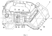
- FIG. 3 shows the speed change mechanism 400, a part of the pump unit 200 in drive connection with the speed change mechanism, and a part of the electric motor assembly 300 in drive connection with the speed change mechanism.
- the speed change mechanism 400 comprises a gearbox shell 410 (shown in FIG. 10 ) as well as a gear 420 and a ring gear 430 which are meshed with each other and accommodated in the gearbox shell.
- the gear 420 is in drive connection with an output shaft 311 of the electric motor assembly 300
- the ring gear 430 is in drive connection with a drive shaft 235 of an impeller 230.
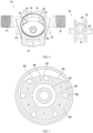
- FIG. 4 shows the ring gear 430.
- the ring gear comprises a main ring gear body 431 on which inner teeth 432 are formed as well as a ring gear extension part 435 extending axially from the main ring gear body 431.
- the ring gear extension part 435 and the drive shaft 235 of the impeller cooperate in such a way that they are unable to rotate relative to each other.
- a shaft hole 436 formed in the ring gear extension part 435 can be in bonded connection, welded connection, clamped connection or threaded connection with the drive shaft 235.
- a contour of an inner wall of the shaft hole 436 and a contour of the drive shaft 235 can be formed to match each other, such as planar contours.
- FIG. 3 shows a first bearing 450.
- the first bearing is disposed around the ring gear extension part 435, and an outer side of the first bearing 450 abuts against a main pump body 210 (see FIG. 9 ).
- FIG. 3 also shows a ring gear shaft 440.
- the ring gear shaft defines a rotation axis of the ring gear 430.
- FIG. 4 shows a bearing seat 433.
- the bearing seat 433 is formed inside the ring gear 430 to accommodate a second bearing 460 (see FIG. 9 ) disposed around the ring gear shaft 440.
- the ring gear 430 further comprises a transition part 438 connecting the main ring gear body 431 to the ring gear extension part 435, and at least one part of the bearing seat 433 is formed in the transition part 438.
- the first bearing 450 and the second bearing 460 are respectively located outside and inside the ring gear 430, and are spaced axially. During operation of the pump unit 200, the first bearing 450 and the second bearing 460 respectively support the rotating ring gear 430 from the outside and the inside to avoid deviation of the rotation axis of ring gear 430.
- the speed change mechanism 400 in this embodiment is used to reduce the output rotation speed of the electric motor assembly 300.
- speed reduction mechanisms in other forms are also applicable to the present utility model, such as a planetary gear train, a worm gear, and a reduction gear train composed of a plurality of meshing spur gears and bevel gears, or their combination.
- a reduction ratio of the speed change mechanism is preferably 2:1 to 10:1, and is more preferably 2.5:1 to 5:1, such as 3:1, 22:7, 26:7, and 4:1.
- the speed change mechanism 400 may comprise a multistage reduction gear to raise the reduction ratio.
- the speed change mechanism 400 can reduce a rotation speed of the electric motor to be equal to a desired rotation speed of the impeller, so that the service life of the impeller is prolonged. Furthermore, the fluid transfer pump of the present utility model can use a small DC highspeed electric motor due to the existence of the speed change mechanism 400. This is conducive to reducing the size of the fluid transfer pump, decreasing energy consumption, and increasing battery life.
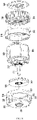
- FIG. 5 shows the pump unit 200 according to an embodiment of the present utility model.
- the pump unit comprises the main pump body 210 and the impeller 230.
- the main pump body 210 defines a pump chamber 220, and the impeller 230 is arranged in the pump chamber 220.
- the impeller 230 comprises the drive shaft 235 in drive connection with the output end of the speed change mechanism 400.
- the drive shaft 235 is in drive connection with the ring gear extension part 435 of the ring gear 430.
- a mounting flange 213 is formed at a rear end of the main pump body 210, and the gearbox shell 410 (see FIG. 10 ) can be fixed to the mounting flange 213.
- the pump unit 200 further comprises a cover plate 260 and a mounting base 270 supporting the cover plate 260.
- the cover plate 260 is used to close the pump chamber 220, and the mounting base 270 is connected to the housing 100 of the fluid transfer pump.
- a sealing plate 240 is additionally arranged between the cover plate 260 and the main pump body 210.
- fastener holes 271, 261, 219 which are aligned axially can be formed in edges of the mounting base 270, the cover plate 260, and the main pump body 210, facilitating assembly and disassembly of the pump unit 200.
- FIG. 6 shows the main pump body 210 and the impeller 230.
- Close nipples 215, 216 extend outward from the main pump body 210 in a direction transverse to the axis of the impeller, so as to form the fluid inlet 201 and fluid outlet 202 of the fluid transfer pump.
- the impeller 230 comprises a hub 231 and a plurality of flexible blades 232 radially extending outward from the hub 231 and spaced from one another in a circumferential direction.
- a hole 234 is formed in the center of the hub 231 to receive the drive shaft 235 such that the impeller 230 rotates together with the drive shaft 235.
- each flexible blade 232 has a roughly cylindrical outer end part 233.
- FIG. 7 shows a cross section of the pump unit 200.
- a wall defining the pump chamber 220 comprises a cam-shaped wall portion 228 and a circular wall portion 229.
- the cam-shaped wall portion 228 comprises a first arc part 223 defining a pump inlet 221, a second arc part 224 defining a pump outlet 222, and a third arc part 225 connected to the first arc part 223 and the second arc part 224.
- the radius of curvature of the first arc part 223, the radius of curvature of the second arc part 224, and the radius of curvature of the third arc part 225 are all smaller than the radius of curvature of the circular wall portion 229.
- the outer end part 233 of the flexible blade 232 is in sliding contact with the cam-shaped wall portion 228 or the circular wall portion 229.
- the flexible blade 232 is obviously deformed due to extrusion of the first arc part 223, the second arc part 224, and the third arc part 225.
- the impeller 230 has six flexible blades 232. As shown in FIG. 7 , when the impeller 230 is put into the pump chamber 220, an adjacent two of the flexible blades 232, an outer wall of the hub 231, and the wall defining the pump chamber 220 jointly define a fluid delivery cavity. In other words, the pump chamber 220 is divided into six fluid delivery cavities A-F by the impeller 230. In FIG. 7 , the two flexible blades 232 in contact with the cam-shaped wall portion 228 (the first arc part 223, the second arc part 224, and the third arc part 225) are significantly deformed, and the four flexible blades 232 in contact with the circular wall portion 229 are not deformed or merely slightly deformed.
- the deformed flexible blades 232 induce a size reduction and pressure rise of the fluid delivery cavities E, F, such that a fluid is forced to flow out via the pump outlet 222 formed in the second arc part 224.
- a negative pressure is generated in the fluid delivery cavity A, such that liquid is sucked into the pump chamber 220 via the pump inlet 221 formed in the first arc part 223.
- a pumping path of the fluid is related to a rotation direction of the impeller 230. If the impeller 230 is driven by the electric motor assembly 300 to rotate counterclockwise, the liquid enters the pump chamber 220 via the pump outlet 222 and is discharged via the pump inlet 221.
- FIG. 8 shows the electric motor assembly 300 according to an embodiment of the present utility model.
- the electric motor assembly 300 comprises an electric motor 310, a fan 320, a front mounting frame 330, a rear mounting frame 340, and a control unit 360.
- the electric motor 310 can be a battery-powered brushless DC electric motor or brushed DC electric motor.
- the fan 320 is arranged at a front end of the electric motor 310 and driven by the electric motor 310.
- a gear 312 is mounted on an output shaft 311 of the electric motor 310 and meshed with teeth 322 formed on a wall of a center hole of the fan 320.
- the fan 320 may be fixed to the output shaft 311 to rotate together with the output shaft 311.
- the fan 320 is used to generate a cooling air flow to accelerate heat dissipation of the electric motor 310, and the fan 320 can be a centrifugal fan.
- the front mounting frame 330 and the rear mounting frame 340 are located at two ends of the electric motor 310, and respectively hold a part of the electric motor 310 to fix the electric motor 310 at a predetermined position.
- the front mounting frame 330 comprises an end plate 331, an annular electric motor cover part 332, and a plurality of connecting bars 333 connecting the end plate 331 to the electric motor cover part 332.
- a hole 334 is formed in the end plate 331 to allow the output shaft 311 to pass through.
- the air flow generated during rotation of the fan 320 can only flow radially outward out of the front mounting frame 330 via a side opening 335 between adjacent connecting bars 333.
- the front mounting frame 330 can guide the cooling air flow to flow in a desired path.
- the control unit 360 is arranged at a rear end of the electric motor 310 to control rotation of the electric motor 310.
- the control unit 360 comprises a circuit board, and an electronic component can be mounted on one side or two sides of the circuit board.
- the control unit 360 can start/stop the electric motor 310 on the basis of an input of the user, or change the rotation speed of the electric motor 310.
- the control unit 360 can also determine, on the basis of operating parameters such as a current value and a voltage value of the electric motor 310, whether or not the electric motor 310 operates normally, and stop the electric motor 310 when an abnormality is found.
- a sensor used to detect pump parameters may be arranged in the fluid transfer pump, such as a pressure sensor, a temperature sensor, and a liquid sensor.
- the control unit 360 can control the electric motor 310 on the basis of the pump parameters detected by the sensor. When the pump parameters reach preset values, the control unit automatically controls the electric motor 310.
- a protective shell 350 is provided for the control unit 360.
- the control unit 360 is located at a rear end of the protective shell 350 or in the protective shell.
- the protective shell 350 can fulfil heat dissipation of the control unit 360.
- the protective shell 350 is connected to the rear mounting frame 340.
- the control unit 360 is provided with a heat dissipation element or a heat conduction element to conduct heat to the protective shell 350 or ambient air.
- the heat dissipation element can be a metal radiator in contact with the circuit board and/or the electronic component, or a heat conductive adhesive used to fix the circuit board to the protective shell 350.
- the heat conductive adhesive basically fills an internal space of the protective shell 350, and the control unit 360 is at least partially embedded into the heat conductive adhesive. Therefore, the control unit 360 is both fixed and radiated by means of the heat conductive adhesive.
- first fastener holes 336 are formed in the connecting bars 333 of the front mounting frame 330; grooves 315 extending axially are formed in an outer surface of a stator core of the electric motor 310; second fastener holes 345 are formed in the rear mounting frame 340; and third fastener holes 355 are formed in the protective shell 350 of the control unit 360.
- the first fastener hole 336, the groove 315, the second fastener hole 345, and the third fastener hole 355 are aligned axially, such that a single fastener 370 (see FIG. 10 ) can connect the front mounting frame 330, the electric motor 310, the rear mounting frame 340, and the protective shell 350.
- the internal space of the housing 100 is divided into a plurality of areas 131, 132, 133 by at least one separator.
- the electric motor 310 and fan 320 of the electric motor assembly 300 are respectively located in different areas. Specifically, the fan 320 is located at a front side (a left side in the figure) of the electric motor 310, and the fan 320 is located in the first area 131; the electric motor 310 is located in the second area 132; and the first area 131 and the second area 132 are separated by a first partition plate 150. In other embodiments, the fan 320 may be arranged at a rear side of the electric motor 310.
- FIG. 9 shows a cross section of the fluid transfer pump.
- the first area 131 is at least partially defined by a first wall part 101 of the housing 100, and a first opening 160 is formed in the first wall part 101 such that the first area 131 communicates with an external environment.
- the centrifugal fan 320 driven by the electric motor 310 enables the cooling air flow to radially outward flow out of the front mounting frame 330.
- the air flow flowing out of the front mounting frame 330 enters the first area 131 of the housing 100. Due to obstruction of the first partition plate 150, the air flow cannot enter the second area 132 where the electric motor 310 is located. Therefore, the air flow in the first area 131 flows out of the housing 100 via the first opening 160.
- the first opening 160 is radially aligned to the fan 320 such that the air flow flows out of the housing 100 along the shortest path and takes away heat generated by the electric motor 310 during operation.
- the first opening 160 serves as an outlet for the cooling air flow.
- the second area 132 is at least partially defined by a second wall part 102 of the housing 100, and a second opening 161 is formed in the second wall part 102 such that the second area 132 communicates with the external environment.
- the electric motor 310 and the control unit 360 located at the rear end of the electric motor 310 are arranged in the second area.
- the second opening 161 serves as an inlet for the cooling air flow to introduce air from the external environment. Due to the obstruction of the first partition plate 150, the cooling air flow passes through the electric motor 310 under a suction effect of the fan 320, so as to realize cooling.
- the cooling air flow heated by the heat generated by the electric motor 310 flows out of the housing 100 via the first opening 160, and thus cannot flow back into the electric motor 310.
- the second opening 161 can be formed above the electric motor 310 as shown in FIG. 9 , or be formed at other positions close to the electric motor 310.
- the cooling air entering the second area 132 via the second opening 161 can also cool the control unit 360 adjacent to the electric motor 310.
- the third area 133 is at least partially defined by a third wall part 103 of the housing 100.
- the third area 133 and the first area 131 are separated by a second partition plate 151, and the pump unit 200 is located in the third area 133. Due to obstruction of the second partition plate 151, the heated cooling air flow cannot enter the third area 133.
- the first partition plate 150 extends from an inner wall of the housing 100 to an outer surface of the electric motor 310
- the second partition plate 151 extends from the inner wall of the housing to an outer surface of the gearbox shell 410.
- a first sealing ring 170 can be arranged between the first partition plate 150 and the outer surface of the electric motor 310
- a second sealing ring 171 can be arranged between the second partition plate 151 and the outer surface of the gearbox shell 410.
- FIG. 10 shows the pump unit 200, the electric motor assembly 300, and the speed change mechanism 400 which are in an assembled state.
- the first sealing ring 170 is disposed around the electric motor 310 and abuts against the front mounting frame 330.
- the second sealing ring 171 is disposed around the gearbox shell 410. Grooves are formed in the first sealing ring 170 and the second sealing ring 171 to achieve a close fit between the first sealing ring and the first partition plate 150 and between the second sealing ring and the second partition plate.
- the first partition plate 150 and the second partition plate 151 can be integrated with the housing 100 or mounted on the housing 100 as independent separators.
- FIG. 10 also shows a positioning component 214.
- the positioning component is arranged between the pump unit 200 and the housing 100 of the fluid transfer pump to hold the pump unit 200 at a predetermined position in the housing 100.
- the positioning component 214 can be made from rubber or other materials with damping characteristics to reduce the vibration of the housing 100 during operation of the pump unit 200 for noise reduction.
- FIG. 11 shows the power supply compartment 500 according to one embodiment of the present utility model.
- the power supply compartment 500 comprises a compartment shell 510 and a cover 520 covering the compartment shell 510.
- the cover 520 is pivotally connected to the compartment shell 510 around a pin 530.
- a torsion spring is arranged on the pin 530 to bias the cover 520 to a closed position or a fully open position.
- the power supply compartment 500 is preferably designed to be waterproof.
- the cover 520 has a first sealing edge 521
- the compartment shell 510 has a second sealing edge 511. When the cover 520 is in the closed position, the first sealing edge 521 is aligned to the second sealing edge 511.
- FIG. 12 shows a cross section of a part of the power supply compartment 500.
- a groove 512 is formed in the second sealing edge 511; and the groove 512 is used to accommodate a sealing component (not shown in the figure), such as an elastic sealing ring.
- the groove used to accommodate the sealing component may be formed in the first sealing edge 521 or formed by both the first sealing edge 521 and the second sealing edge 511.
- At least one of the first sealing edge 521 and the second sealing edge 511 can have a ridge part 523, 513 extending outward. When the cover 520 is in the closed position, the ridge part 523, 513 abuts against the sealing component to hold the sealing component at a sealing position.
- FIG. 11 also shows the power supply mounting base 550 and a locking component 540.
- the power supply mounting base 550 is arranged on a side of the power supply compartment 500 that is close to the electric motor assembly 300.
- the power supply mounting base 550 comprises a positioning part used to fix a battery and a contact part electrically connected to the battery.
- the power supply mounting base 550 is formed as a part of an inner wall of the power supply compartment 500, guide rails 514 used to guide the battery are formed on the compartment shell 510, and the guide rails 514 are located on two sides of the power supply mounting base 550.
- the locking component 540 is used to lock the cover 520 in the closed position.
- the locking component 540 is able to move between a locked position and an unlocked position under operation performed by the user.
- When the locking component is in the locked position at least one part of the locking component 540 presses against the first sealing edge 521 of the cover 520 to prevent the cover 520 from leaving the closed position.
- the compartment shell 510 comprises a protrusion part 515 extending from the second sealing edge 511, and the locking component 540 is arranged on the protrusion part 515.
- the locking component 540 is formed as a locking knob 541 which has a locking part 542.
- the first sealing edge 521 of the cover 520 is provided with a protrusive locking fitting part 522, and a groove for accommodating the locking part 542 can be formed in the locking fitting part 522.
- a protrusive locking fitting part 522 When the user turns the locking knob 541 toward the locked position, the locking knob 541 is obstructed by the locking fitting part 522. The user needs to apply a certain force to move the locking knob 541 onto the locking fitting part 522 until the locking part 542 enters the groove in the locking fitting part 522.
- force feedback perceived by the user can assist the user in confirming whether or not the locking knob 541 is in the correct locked position.
- the locking knob 541 shown in FIG. 12 is in the locked position.
- the locking knob 541 comprises a rod 543 which extends downward, and the rod 543 penetrates through a through hole 516 formed in the protrusion part 515 of the cover 520.
- the rod 543 is connected to a fastener 544.
- the fastener 544 can be a screw engaged with a threaded hole formed in a tail end of the rod 543.
- a baffle plate 546 is arranged between a head part of the fastener 544 and the tail end of the rod 543.
- a biasing component 545 such as a spring is arranged between the baffle plate 546 and a bottom surface 517 of the protrusion part 515.
- the biasing component 545 applies a biasing force to the baffle plate 546 to pull the locking component 540 downward, such that the locking knob 541 is held on the protrusion part 515.
- the locking knob 541 can be lifted by the locking fitting part 522 at the first sealing edge 521, such that the baffle plate 546 moves upward.
- the distance between the baffle plate 546 and the bottom surface 517 of the protrusion part 515 becomes smaller, such that the biasing component 545 between them is compressed.
- the biasing component 545 under compression applies a higher biasing force to the baffle plate 546 to resist upward movement of the locking knob 541; and in this way, the locking knob 541 is prevented from falling out of the protrusion part 515.
- FIG. 13 shows one of the half housings assembled to form the housing 100.
- An upper part of the half housing is formed as the handle 110, and a lower part of the half housing is formed as the base 180.
- the base 180 has a front support part 181 and a rear support part 182, and bottom surfaces of the front support part and the rear support part make contact with the ground or other supporting surfaces.
- the base 180 further comprises an elevation part 183 which is elevated relative to the bottom surfaces of the front support part 181 and the rear support part 182.
- the front support part 181 is roughly located below the pump unit 200; the rear support part 182 is roughly located below the power supply compartment 500; and the elevation part 183 is roughly located below the electric motor assembly 300.
- the liquid may unexpectedly enter the housing 100.
- rainwater may enter the housing 100 via the first opening 160 and the second opening 161 in the housing.
- at least one of the support parts 181, 182 and the elevation part 183 can be provided with a hole 191, 192, 193 that enables the internal space of the housing 100 to communicate with the external environment.
- the hole 191 in the front support part 181 allows leaked liquid to flow out of the housing 100.
- the elevation part 183 is a certain distance away from the ground, so as to reduce the possibility of water or debris on the ground entering the first area 131 and the second area 132, thereby protecting the electric motor assembly 300.
- the elevation part 183 comprises a bottom wall 184 and a baffle plate 185 located on an inner side of the bottom wall 184, the hole 193 is formed in the bottom wall, and a tortuous path from the hole 193 to the internal space of the housing is defined by the baffle plate 185.
- cooling air can enter the second area 132 via the hole 193 or exit from the first area 131 via the hole 193, and the baffle plate 185 can prevent the litter from entering the housing via the hole 193.
Landscapes
- Engineering & Computer Science (AREA)
- Mechanical Engineering (AREA)
- General Engineering & Computer Science (AREA)
- Structures Of Non-Positive Displacement Pumps (AREA)
Abstract
Description
- The present utility model relates to a fluid transfer pump, in particular to a portable fluid transfer pump driven by an electric motor.
- A fluid transfer pump driven by an electric motor transfers water or other fluids from one position to another by means of a pump unit. An inlet of the pump can be connected to a fluid source such as a water pool via an input pipe. An outlet of the pump can be connected to a discharge pipe such as a standard garden hose to transfer a discharged fluid to a desired position. A type of fluid transfer pump performs the suction and discharge of the fluid by the rotation of an impeller.
- The fluid transfer pump is typically connected to a power supply through an electric wire. In recent years, a battery-powered fluid transfer pump is emerging. The battery-powered fluid transfer pump is popular with users due to its portability. However, this cordless pump has some shortcomings, such as a large size, a heavy weight, a complex structure, a short battery life, and a low heat dissipation efficiency of the electric motor.
- Thus, it is necessary to develop a portable fluid transfer pump having a compact structure, with ease of assembly, a prolonged battery life, and improved heat dissipation performance.
- To achieve the above objective, the present utility model provides a fluid transfer pump. The fluid transfer pump comprises: a housing, a pump unit, an electric motor assembly, a power supply mounting base, and a speed change mechanism, wherein the pump unit comprises an impeller; the electric motor assembly is used to drive the impeller to rotate around an axis of the impeller; the power supply mounting base is used to receive a power supply for supplying electricity to the pump unit; and the speed change mechanism is arranged between the pump unit and the electric motor assembly.
- Preferably, the power supply mounting base is arranged in a power supply compartment; the pump unit, the speed change mechanism, the electric motor assembly, and the power supply compartment are successively arrayed in an extension direction of the axis of the impeller; and the power supply can be guided into the power supply compartment in a mounting direction. Viewed from a side, an axis in the mounting direction is inclined at an angle relative to the axis of the impeller.
- The speed change mechanism can be used to reduce an output rotation speed of the electric motor assembly. Preferably, the speed change mechanism can comprise a gearbox shell as well as a gear and a ring gear which are meshed with each other and accommodated in the gearbox shell; and the gear is in drive connection with an output shaft of the electric motor assembly, and the ring gear is in drive connection with a drive shaft of the impeller. In one embodiment, the ring gear comprises a main ring gear body on which inner teeth are formed as well as a ring gear extension part extending axially from the main ring gear body, and the ring gear extension part matches the drive shaft of the impeller. A first bearing can be disposed around the ring gear extension part. The ring gear can comprise a ring gear shaft which defines a rotational axis of the ring gear; a bearing seat is formed in the ring gear; and a second bearing disposed around the ring gear shaft is accommodated in the bearing seat. The ring gear can comprise a transition part connecting the main ring gear body to the ring gear extension part, and at least one part of the bearing seat is formed in the transition part. The gearbox shell can be fixed to a mounting flange located at one end of the housing of the pump unit.
- In one aspect, the power supply compartment can comprise a compartment shell and a cover pivotally connected to the compartment shell; the cover has a first sealing edge, and the compartment shell has a second sealing edge aligned to the first sealing edge; and a groove used to accommodate at least one part of a sealing component is formed in at least one of the first sealing edge and the second sealing edge. Preferably, at least one of the first sealing edge and the second sealing edge has a ridge part extending outward; and when the cover is in a closed position, the ridge part abuts against the sealing component.
- In one aspect, the fluid transfer pump can comprise a locking component used to lock the cover in the closed position; the locking component is able to move between a locked position and an unlocked position; and when the locking component is in the locked position, at least one part of the locking component presses against the first sealing edge of the cover. Preferably, the compartment shell comprises a protrusion part extending from the second sealing edge, the locking component is held on the protrusion part through a biasing component, and the biasing component applies a biasing force to the locking component to resist movement of the locking component away from the protrusion part.
- In one aspect, an internal space of the housing can be divided into a plurality of areas by at least one separator; the electric motor assembly comprises an electric motor, and a fan driven by the electric motor and adjacent to one end of the electric motor; and the fan and the other end of the electric motor are respectively located in different areas. Preferably, the fan is located in a first area, the first area is at least partially defined by a first wall part of the housing, and a first opening is formed in the first wall part such that the first area communicates with an external environment. Preferably, the first opening is radially aligned to the fan. The other end of the electric motor is located in a second area, the second area is at least partially defined by a second wall part of the housing, and a second opening is formed in the second wall part such that the second area communicates with the external environment. Preferably, the second opening is located above the electric motor. The first area and the second area are separated by a first partition plate extending from an inner wall of the housing, and the first partition plate is in a close fit with a first sealing ring disposed around the electric motor assembly. The pump unit is located in a third area, and the third area and the first area are separated by a second partition plate extending from the inner wall of the housing. The second partition plate is in a close fit with the second sealing ring disposed around the gearbox shell.
- In one aspect, the fluid transfer pump can comprise a base; the base has support parts and an elevation part elevated relative to bottom surfaces of the support parts; and a hole via which an internal space of the housing communicates with the external environment is formed in at least one of the support parts and the elevation part. Preferably, the elevation part is located below the electric motor assembly, the elevation part comprises a bottom wall and a baffle plate located on an inner side of the bottom wall, the hole is formed in the bottom wall, and a tortuous path from the hole to the internal space of the housing is defined by the baffle plate.
-
-
FIG. 1 shows a fluid transfer pump according to an embodiment of the present utility model. -
FIG. 2 shows an internal structure of the fluid transfer pump. -
FIG. 3 shows a speed change mechanism, a part of a pump unit, and a part of an electric motor assembly of the fluid transfer pump. -
FIG. 4 shows a ring gear of the speed change mechanism. -
FIG. 5 shows a pump unit according to an embodiment of the present utility model. -
FIG. 6 shows a main pump body of the pump unit and an impeller. -
FIG. 7 shows a cross section of the pump unit. -
FIG. 8 shows an electric motor assembly according to an embodiment of the present utility model. -
FIG. 9 shows a cross section of the fluid transfer pump. -
FIG. 10 shows the pump unit, the electric motor assembly, and the speed change mechanism which are in an assembled state. -
FIG. 11 shows a power supply compartment according to an embodiment of the present utility model. -
FIG. 12 shows a cross section of a part of the power supply compartment. -
FIG. 13 shows a half housing of the fluid transfer pump. -
FIG. 1 shows a fluid transfer pump, which is used to pump a fluid such as water, according to an embodiment of the present utility model. The fluid transfer pump comprises ahousing 100 and apump unit 200 accommodated in thehousing 100. The pump unit comprises afluid inlet 201 used to be connected to an input pipe and afluid outlet 202 used to be connected to a discharge pipe. In this embodiment, thepump unit 200 is arranged at a front part (a left side inFIG. 1 ) of thehousing 100, and thefluid inlet 201 and thefluid outlet 202 respectively extend from two sides of thehousing 100. In other embodiments, thepump unit 200 may be arranged at other positions in the housing. Thefluid inlet 201 and thefluid outlet 202 may be arranged in an upper side, a front end, or a rear end of the housing. Abase 180 stably supports the fluid transfer pump on the ground or other supporting surfaces. Thebase 180 can be integrated with thehousing 100 or be independent of the housing. - The fluid transfer pump shown in
FIG. 1 can be powered by a portable power supply. The portable power supply can be a lithium battery and is removably mounted on the fluid transfer pump. In the illustrated embodiment, the fluid transfer pump comprises apower supply compartment 500 located at a rear part (a right side inFIG. 1 ) of thehousing 100, and a power supply for supplying electricity to thepump unit 200 is accommodated in thepower supply compartment 500. The fluid transfer pump further comprises ahandle 110 for a user to grasp. Thehandle 110 can be located above thehousing 100 and connected to the front part and rear part of thehousing 100. As shown inFIG. 1 , one end of thehandle 110 is adjacent to thefluid inlet 201 and thefluid outlet 202, and the other end of the handle is adjacent to thepower supply compartment 500. - The
handle 110 can be integrated with thehousing 100 or be mounted on thehousing 100 as an independent component. Thehandle 110 comprises a grasping part, the size and contour of which conform to a palm of the user. The grasping part can be covered with an elastic material such as rubber, which is deformable when the grasping part is grasped by the user, so as to improve grasping comfort. At least one part of the grasping part can be covered with pits or ridges to prevent the handle from slipping out of a hand of the user. Preferably, when the fluid transfer pump is put onto the ground, the grasping part of thehandle 110 intersects a vertical line passing through the center of gravity of the whole fluid transfer pump. The position of the grasping part is conducive to saving the force required by the user to lift the fluid transfer pump and relieving shaking of the fluid transfer pump during movement. - An operating unit used to control the fluid transfer pump can be arranged on the
handle 110.FIG. 1 shows abutton 120. The button is located at a front part of thehandle 110, such that a thumb of the user can naturally touch thebutton 120 when the user grasps thehandle 110. In addition, acontrol key 130 and astatus indicator 140 can be arranged on thehousing 100. In an embodiment, thebutton 120 is used to start and stop the fluid transfer pump, and thecontrol key 130 allows the user to adjust the power and/or speed of an electric motor, or to set an operating time of the electric motor. Thestate indicator 140 can include a plurality ofLED lights 140 or other types of display devices which are used to display the current power and/or speed level, or continuous operating time and remaining operating time of the pump unit, and other information. In other embodiments, thehandle 110 and/or thehousing 100 may be provided with a control and display unit such as a locking button, a pumping mode switching button, a timer button, and an electronic display screen to assist the user in operating the fluid transfer pump. -
FIG. 2 shows one side of the fluid transfer pump. In this embodiment, thehousing 100 is formed by assembling two half housings. In order to clearly show an internal structure, one of the half housings has been removed. Thepump unit 200 and thepower supply compartment 500 are respectively located on two sides of thehousing 100, and anelectric motor assembly 300 used to drive thepump unit 200 to operate is located between thepump unit 200 and thepower supply compartment 500 and is approximately in the middle of thewhole housing 100. Such a configuration can enable thepower supply compartment 500 to be furthest away from a fluid source. Aspeed change mechanism 400 is arranged between thepump unit 200 and theelectric motor assembly 300, and is used to change an output rotation speed of theelectric motor assembly 300. An impeller in thepump unit 200 is in drive connection with an output end of thespeed change mechanism 400, and is driven by theelectric motor assembly 300 and thespeed change mechanism 400 to rotate along an axis L1 of the impeller. It can be seen fromFIG. 2 that thepump unit 200, thespeed change mechanism 400, theelectric motor assembly 300, and thepower supply compartment 500 are successively arrayed in an extension direction of the axis L1 of the impeller. - A power
supply mounting base 550 is arranged in thepower supply compartment 500 to receive the power supply for supplying the electricity to thepump unit 200, such as a battery pack capable of being repeatedly recharged. The battery pack can be guided into thepower supply compartment 500 in a mounting direction. An axis L2 in the mounting direction is inclined at an angle relative to the axis L1 of the impeller. In the embodiment shown inFIG. 2 , this angle is less than 90°, preferably between 15° and 75°, and more preferably between 30° and 60°. Thepower supply compartment 500 is obliquely arranged to make the most of an internal space of thehousing 100, enable the powersupply mounting base 550 to be closer to theelectric motor assembly 300, and make it convenient for the user to install and remove the power supply. In other embodiments, in order to further reduce the size of the fluid transfer pump, thehousing 100 is not provided with thepower supply compartment 500, and the powersupply mounting base 550 may be arranged on an outer surface of the housing, such as a top surface or a side surface. In these embodiments, the battery pack is directly mounted on the outer surface of thehousing 100. In other embodiments, a separate power supply box may be provided and electrically connected to thepump unit 200. -
FIG. 3 shows thespeed change mechanism 400, a part of thepump unit 200 in drive connection with the speed change mechanism, and a part of theelectric motor assembly 300 in drive connection with the speed change mechanism. In this embodiment, thespeed change mechanism 400 comprises a gearbox shell 410 (shown inFIG. 10 ) as well as agear 420 and aring gear 430 which are meshed with each other and accommodated in the gearbox shell. Thegear 420 is in drive connection with anoutput shaft 311 of theelectric motor assembly 300, and thering gear 430 is in drive connection with adrive shaft 235 of animpeller 230. -
FIG. 4 shows thering gear 430. The ring gear comprises a mainring gear body 431 on whichinner teeth 432 are formed as well as a ringgear extension part 435 extending axially from the mainring gear body 431. The ringgear extension part 435 and thedrive shaft 235 of the impeller cooperate in such a way that they are unable to rotate relative to each other. For example, ashaft hole 436 formed in the ringgear extension part 435 can be in bonded connection, welded connection, clamped connection or threaded connection with thedrive shaft 235. Alternatively, a contour of an inner wall of theshaft hole 436 and a contour of thedrive shaft 235 can be formed to match each other, such as planar contours. -
FIG. 3 shows afirst bearing 450. The first bearing is disposed around the ringgear extension part 435, and an outer side of thefirst bearing 450 abuts against a main pump body 210 (seeFIG. 9 ).FIG. 3 also shows aring gear shaft 440. The ring gear shaft defines a rotation axis of thering gear 430.FIG. 4 shows abearing seat 433. Thebearing seat 433 is formed inside thering gear 430 to accommodate a second bearing 460 (seeFIG. 9 ) disposed around thering gear shaft 440. Thering gear 430 further comprises atransition part 438 connecting the mainring gear body 431 to the ringgear extension part 435, and at least one part of thebearing seat 433 is formed in thetransition part 438. Thefirst bearing 450 and thesecond bearing 460 are respectively located outside and inside thering gear 430, and are spaced axially. During operation of thepump unit 200, thefirst bearing 450 and thesecond bearing 460 respectively support therotating ring gear 430 from the outside and the inside to avoid deviation of the rotation axis ofring gear 430. - The
speed change mechanism 400 in this embodiment is used to reduce the output rotation speed of theelectric motor assembly 300. Technical personnel can understand that speed reduction mechanisms in other forms are also applicable to the present utility model, such as a planetary gear train, a worm gear, and a reduction gear train composed of a plurality of meshing spur gears and bevel gears, or their combination. A reduction ratio of the speed change mechanism is preferably 2:1 to 10:1, and is more preferably 2.5:1 to 5:1, such as 3:1, 22:7, 26:7, and 4:1. In other embodiments, thespeed change mechanism 400 may comprise a multistage reduction gear to raise the reduction ratio. Thespeed change mechanism 400 can reduce a rotation speed of the electric motor to be equal to a desired rotation speed of the impeller, so that the service life of the impeller is prolonged. Furthermore, the fluid transfer pump of the present utility model can use a small DC highspeed electric motor due to the existence of thespeed change mechanism 400. This is conducive to reducing the size of the fluid transfer pump, decreasing energy consumption, and increasing battery life. -
FIG. 5 shows thepump unit 200 according to an embodiment of the present utility model. The pump unit comprises themain pump body 210 and theimpeller 230. Themain pump body 210 defines apump chamber 220, and theimpeller 230 is arranged in thepump chamber 220. Theimpeller 230 comprises thedrive shaft 235 in drive connection with the output end of thespeed change mechanism 400. In this embodiment, thedrive shaft 235 is in drive connection with the ringgear extension part 435 of thering gear 430. A mountingflange 213 is formed at a rear end of themain pump body 210, and the gearbox shell 410 (seeFIG. 10 ) can be fixed to the mountingflange 213. Anannular groove 217 is formed in an outer surface of afront end 212 of themain pump body 210, and asealing ring 250 is accommodated in the annular groove. Thepump unit 200 further comprises acover plate 260 and a mountingbase 270 supporting thecover plate 260. Thecover plate 260 is used to close thepump chamber 220, and the mountingbase 270 is connected to thehousing 100 of the fluid transfer pump. Optionally, a sealingplate 240 is additionally arranged between thecover plate 260 and themain pump body 210. In addition, fastener holes 271, 261, 219 which are aligned axially can be formed in edges of the mountingbase 270, thecover plate 260, and themain pump body 210, facilitating assembly and disassembly of thepump unit 200. -
FIG. 6 shows themain pump body 210 and theimpeller 230.Close nipples main pump body 210 in a direction transverse to the axis of the impeller, so as to form thefluid inlet 201 andfluid outlet 202 of the fluid transfer pump. Theimpeller 230 comprises ahub 231 and a plurality offlexible blades 232 radially extending outward from thehub 231 and spaced from one another in a circumferential direction. Ahole 234 is formed in the center of thehub 231 to receive thedrive shaft 235 such that theimpeller 230 rotates together with thedrive shaft 235. Optionally, eachflexible blade 232 has a roughly cylindricalouter end part 233. -
FIG. 7 shows a cross section of thepump unit 200. A wall defining thepump chamber 220 comprises a cam-shapedwall portion 228 and acircular wall portion 229. With reference toFIG. 6 and FIG. 7 , it can be seen that the cam-shapedwall portion 228 comprises afirst arc part 223 defining apump inlet 221, asecond arc part 224 defining apump outlet 222, and athird arc part 225 connected to thefirst arc part 223 and thesecond arc part 224. In this embodiment, the radius of curvature of thefirst arc part 223, the radius of curvature of thesecond arc part 224, and the radius of curvature of thethird arc part 225 are all smaller than the radius of curvature of thecircular wall portion 229. When theimpeller 230 rotates in thepump chamber 220, theouter end part 233 of theflexible blade 232 is in sliding contact with the cam-shapedwall portion 228 or thecircular wall portion 229. When in sliding contact with the cam-shapedwall portion 228, theflexible blade 232 is obviously deformed due to extrusion of thefirst arc part 223, thesecond arc part 224, and thethird arc part 225. - In this embodiment, the
impeller 230 has sixflexible blades 232. As shown inFIG. 7 , when theimpeller 230 is put into thepump chamber 220, an adjacent two of theflexible blades 232, an outer wall of thehub 231, and the wall defining thepump chamber 220 jointly define a fluid delivery cavity. In other words, thepump chamber 220 is divided into six fluid delivery cavities A-F by theimpeller 230. InFIG. 7 , the twoflexible blades 232 in contact with the cam-shaped wall portion 228 (thefirst arc part 223, thesecond arc part 224, and the third arc part 225) are significantly deformed, and the fourflexible blades 232 in contact with thecircular wall portion 229 are not deformed or merely slightly deformed. When theimpeller 230 rotates clockwise, the deformedflexible blades 232 induce a size reduction and pressure rise of the fluid delivery cavities E, F, such that a fluid is forced to flow out via thepump outlet 222 formed in thesecond arc part 224. At the same time, a negative pressure is generated in the fluid delivery cavity A, such that liquid is sucked into thepump chamber 220 via thepump inlet 221 formed in thefirst arc part 223. It should be understood that a pumping path of the fluid is related to a rotation direction of theimpeller 230. If theimpeller 230 is driven by theelectric motor assembly 300 to rotate counterclockwise, the liquid enters thepump chamber 220 via thepump outlet 222 and is discharged via thepump inlet 221. -
FIG. 8 shows theelectric motor assembly 300 according to an embodiment of the present utility model. Theelectric motor assembly 300 comprises anelectric motor 310, afan 320, afront mounting frame 330, arear mounting frame 340, and acontrol unit 360. Theelectric motor 310 can be a battery-powered brushless DC electric motor or brushed DC electric motor. Thefan 320 is arranged at a front end of theelectric motor 310 and driven by theelectric motor 310. Agear 312 is mounted on anoutput shaft 311 of theelectric motor 310 and meshed withteeth 322 formed on a wall of a center hole of thefan 320. In other embodiments, thefan 320 may be fixed to theoutput shaft 311 to rotate together with theoutput shaft 311. Thefan 320 is used to generate a cooling air flow to accelerate heat dissipation of theelectric motor 310, and thefan 320 can be a centrifugal fan. Thefront mounting frame 330 and therear mounting frame 340 are located at two ends of theelectric motor 310, and respectively hold a part of theelectric motor 310 to fix theelectric motor 310 at a predetermined position. Thefront mounting frame 330 comprises anend plate 331, an annular electricmotor cover part 332, and a plurality of connectingbars 333 connecting theend plate 331 to the electricmotor cover part 332. Ahole 334 is formed in theend plate 331 to allow theoutput shaft 311 to pass through. After assembly is completed, thefan 320 is located in thefront mounting frame 330. Due to obstruction of theend plate 331, the air flow generated during rotation of thefan 320 can only flow radially outward out of thefront mounting frame 330 via aside opening 335 between adjacent connectingbars 333. Thus, thefront mounting frame 330 can guide the cooling air flow to flow in a desired path. - In the embodiment shown in
FIG. 8 , thecontrol unit 360 is arranged at a rear end of theelectric motor 310 to control rotation of theelectric motor 310. Thecontrol unit 360 comprises a circuit board, and an electronic component can be mounted on one side or two sides of the circuit board. Thecontrol unit 360 can start/stop theelectric motor 310 on the basis of an input of the user, or change the rotation speed of theelectric motor 310. Thecontrol unit 360 can also determine, on the basis of operating parameters such as a current value and a voltage value of theelectric motor 310, whether or not theelectric motor 310 operates normally, and stop theelectric motor 310 when an abnormality is found. In other embodiments, a sensor used to detect pump parameters may be arranged in the fluid transfer pump, such as a pressure sensor, a temperature sensor, and a liquid sensor. Thecontrol unit 360 can control theelectric motor 310 on the basis of the pump parameters detected by the sensor. When the pump parameters reach preset values, the control unit automatically controls theelectric motor 310. - In one embodiment, a
protective shell 350 is provided for thecontrol unit 360. Thecontrol unit 360 is located at a rear end of theprotective shell 350 or in the protective shell. Theprotective shell 350 can fulfil heat dissipation of thecontrol unit 360. As shown inFIG. 8 , theprotective shell 350 is connected to therear mounting frame 340. Optionally, thecontrol unit 360 is provided with a heat dissipation element or a heat conduction element to conduct heat to theprotective shell 350 or ambient air. The heat dissipation element can be a metal radiator in contact with the circuit board and/or the electronic component, or a heat conductive adhesive used to fix the circuit board to theprotective shell 350. In some embodiments, the heat conductive adhesive basically fills an internal space of theprotective shell 350, and thecontrol unit 360 is at least partially embedded into the heat conductive adhesive. Therefore, thecontrol unit 360 is both fixed and radiated by means of the heat conductive adhesive. - For the sake of convenience for assembly, mounting features can be provided for all components of the
electric motor assembly 300. As shown inFIG. 8 , first fastener holes 336 are formed in the connectingbars 333 of thefront mounting frame 330;grooves 315 extending axially are formed in an outer surface of a stator core of theelectric motor 310; second fastener holes 345 are formed in therear mounting frame 340; and third fastener holes 355 are formed in theprotective shell 350 of thecontrol unit 360. Thefirst fastener hole 336, thegroove 315, thesecond fastener hole 345, and thethird fastener hole 355 are aligned axially, such that a single fastener 370 (seeFIG. 10 ) can connect thefront mounting frame 330, theelectric motor 310, therear mounting frame 340, and theprotective shell 350. - Returning to
FIG. 2 , it shows that the internal space of thehousing 100 is divided into a plurality ofareas electric motor 310 andfan 320 of theelectric motor assembly 300 are respectively located in different areas. Specifically, thefan 320 is located at a front side (a left side in the figure) of theelectric motor 310, and thefan 320 is located in thefirst area 131; theelectric motor 310 is located in thesecond area 132; and thefirst area 131 and thesecond area 132 are separated by afirst partition plate 150. In other embodiments, thefan 320 may be arranged at a rear side of theelectric motor 310. -
FIG. 9 shows a cross section of the fluid transfer pump. Thefirst area 131 is at least partially defined by afirst wall part 101 of thehousing 100, and afirst opening 160 is formed in thefirst wall part 101 such that thefirst area 131 communicates with an external environment. As described above, thecentrifugal fan 320 driven by theelectric motor 310 enables the cooling air flow to radially outward flow out of thefront mounting frame 330. The air flow flowing out of thefront mounting frame 330 enters thefirst area 131 of thehousing 100. Due to obstruction of thefirst partition plate 150, the air flow cannot enter thesecond area 132 where theelectric motor 310 is located. Therefore, the air flow in thefirst area 131 flows out of thehousing 100 via thefirst opening 160. Preferably, thefirst opening 160 is radially aligned to thefan 320 such that the air flow flows out of thehousing 100 along the shortest path and takes away heat generated by theelectric motor 310 during operation. Thefirst opening 160 serves as an outlet for the cooling air flow. - The
second area 132 is at least partially defined by asecond wall part 102 of thehousing 100, and asecond opening 161 is formed in thesecond wall part 102 such that thesecond area 132 communicates with the external environment. Theelectric motor 310 and thecontrol unit 360 located at the rear end of theelectric motor 310 are arranged in the second area. In this embodiment, thesecond opening 161 serves as an inlet for the cooling air flow to introduce air from the external environment. Due to the obstruction of thefirst partition plate 150, the cooling air flow passes through theelectric motor 310 under a suction effect of thefan 320, so as to realize cooling. The cooling air flow heated by the heat generated by theelectric motor 310 flows out of thehousing 100 via thefirst opening 160, and thus cannot flow back into theelectric motor 310. Thesecond opening 161 can be formed above theelectric motor 310 as shown inFIG. 9 , or be formed at other positions close to theelectric motor 310. In addition, the cooling air entering thesecond area 132 via thesecond opening 161 can also cool thecontrol unit 360 adjacent to theelectric motor 310. - The
third area 133 is at least partially defined by athird wall part 103 of thehousing 100. Thethird area 133 and thefirst area 131 are separated by asecond partition plate 151, and thepump unit 200 is located in thethird area 133. Due to obstruction of thesecond partition plate 151, the heated cooling air flow cannot enter thethird area 133. - As shown in
FIG. 9 , thefirst partition plate 150 extends from an inner wall of thehousing 100 to an outer surface of theelectric motor 310, and thesecond partition plate 151 extends from the inner wall of the housing to an outer surface of thegearbox shell 410. In order to improve sealing performance, afirst sealing ring 170 can be arranged between thefirst partition plate 150 and the outer surface of theelectric motor 310, and asecond sealing ring 171 can be arranged between thesecond partition plate 151 and the outer surface of thegearbox shell 410. -
FIG. 10 shows thepump unit 200, theelectric motor assembly 300, and thespeed change mechanism 400 which are in an assembled state. Thefirst sealing ring 170 is disposed around theelectric motor 310 and abuts against thefront mounting frame 330. Thesecond sealing ring 171 is disposed around thegearbox shell 410. Grooves are formed in thefirst sealing ring 170 and thesecond sealing ring 171 to achieve a close fit between the first sealing ring and thefirst partition plate 150 and between the second sealing ring and the second partition plate. Thefirst partition plate 150 and thesecond partition plate 151 can be integrated with thehousing 100 or mounted on thehousing 100 as independent separators. In addition,FIG. 10 also shows apositioning component 214. The positioning component is arranged between thepump unit 200 and thehousing 100 of the fluid transfer pump to hold thepump unit 200 at a predetermined position in thehousing 100. Thepositioning component 214 can be made from rubber or other materials with damping characteristics to reduce the vibration of thehousing 100 during operation of thepump unit 200 for noise reduction. -
FIG. 11 shows thepower supply compartment 500 according to one embodiment of the present utility model. Thepower supply compartment 500 comprises acompartment shell 510 and acover 520 covering thecompartment shell 510. Thecover 520 is pivotally connected to thecompartment shell 510 around apin 530. Optionally, a torsion spring is arranged on thepin 530 to bias thecover 520 to a closed position or a fully open position. In order to prevent the fluid from entering thepower supply compartment 500 and making contact with the power supply and the powersupply mounting base 550, thepower supply compartment 500 is preferably designed to be waterproof. In this embodiment, thecover 520 has afirst sealing edge 521, and thecompartment shell 510 has asecond sealing edge 511. When thecover 520 is in the closed position, thefirst sealing edge 521 is aligned to thesecond sealing edge 511. -
FIG. 12 shows a cross section of a part of thepower supply compartment 500. To achieve sealing, agroove 512 is formed in thesecond sealing edge 511; and thegroove 512 is used to accommodate a sealing component (not shown in the figure), such as an elastic sealing ring. In other embodiments, the groove used to accommodate the sealing component may be formed in thefirst sealing edge 521 or formed by both thefirst sealing edge 521 and thesecond sealing edge 511. At least one of thefirst sealing edge 521 and thesecond sealing edge 511 can have aridge part cover 520 is in the closed position, theridge part -
FIG. 11 also shows the powersupply mounting base 550 and alocking component 540. The powersupply mounting base 550 is arranged on a side of thepower supply compartment 500 that is close to theelectric motor assembly 300. The powersupply mounting base 550 comprises a positioning part used to fix a battery and a contact part electrically connected to the battery. In this embodiment, the powersupply mounting base 550 is formed as a part of an inner wall of thepower supply compartment 500,guide rails 514 used to guide the battery are formed on thecompartment shell 510, and theguide rails 514 are located on two sides of the powersupply mounting base 550. - The
locking component 540 is used to lock thecover 520 in the closed position. Thelocking component 540 is able to move between a locked position and an unlocked position under operation performed by the user. When the locking component is in the locked position, at least one part of thelocking component 540 presses against thefirst sealing edge 521 of thecover 520 to prevent thecover 520 from leaving the closed position. Thecompartment shell 510 comprises aprotrusion part 515 extending from thesecond sealing edge 511, and thelocking component 540 is arranged on theprotrusion part 515. In the embodiments shown inFIG. 11 andFIG. 12 , thelocking component 540 is formed as a lockingknob 541 which has a lockingpart 542. Thefirst sealing edge 521 of thecover 520 is provided with a protrusive lockingfitting part 522, and a groove for accommodating thelocking part 542 can be formed in the lockingfitting part 522. When the user turns the lockingknob 541 toward the locked position, the lockingknob 541 is obstructed by the lockingfitting part 522. The user needs to apply a certain force to move the lockingknob 541 onto the lockingfitting part 522 until the lockingpart 542 enters the groove in the lockingfitting part 522. When the user operates the lockingknob 541, force feedback perceived by the user can assist the user in confirming whether or not the lockingknob 541 is in the correct locked position. - The locking
knob 541 shown inFIG. 12 is in the locked position. The lockingknob 541 comprises arod 543 which extends downward, and therod 543 penetrates through a throughhole 516 formed in theprotrusion part 515 of thecover 520. Therod 543 is connected to afastener 544. Thefastener 544 can be a screw engaged with a threaded hole formed in a tail end of therod 543. Abaffle plate 546 is arranged between a head part of thefastener 544 and the tail end of therod 543. Abiasing component 545 such as a spring is arranged between thebaffle plate 546 and abottom surface 517 of theprotrusion part 515. When the lockingknob 541 is in the unlocked position, thebiasing component 545 applies a biasing force to thebaffle plate 546 to pull thelocking component 540 downward, such that the lockingknob 541 is held on theprotrusion part 515. When the user turns the lockingknob 541 to the locked position, the lockingknob 541 can be lifted by the lockingfitting part 522 at thefirst sealing edge 521, such that thebaffle plate 546 moves upward. At this time, the distance between thebaffle plate 546 and thebottom surface 517 of theprotrusion part 515 becomes smaller, such that thebiasing component 545 between them is compressed. Thebiasing component 545 under compression applies a higher biasing force to thebaffle plate 546 to resist upward movement of the lockingknob 541; and in this way, the lockingknob 541 is prevented from falling out of theprotrusion part 515. -
FIG. 13 shows one of the half housings assembled to form thehousing 100. An upper part of the half housing is formed as thehandle 110, and a lower part of the half housing is formed as thebase 180. Thebase 180 has afront support part 181 and arear support part 182, and bottom surfaces of the front support part and the rear support part make contact with the ground or other supporting surfaces. The base 180 further comprises anelevation part 183 which is elevated relative to the bottom surfaces of thefront support part 181 and therear support part 182. In an embodiment, thefront support part 181 is roughly located below thepump unit 200; therear support part 182 is roughly located below thepower supply compartment 500; and theelevation part 183 is roughly located below theelectric motor assembly 300. - In some cases, the liquid may unexpectedly enter the
housing 100. For example, during operation on rainy days, rainwater may enter thehousing 100 via thefirst opening 160 and thesecond opening 161 in the housing. To avoid accumulation of the liquid in thehousing 100, at least one of thesupport parts elevation part 183 can be provided with ahole housing 100 to communicate with the external environment. When thepump unit 200 leaks, thehole 191 in thefront support part 181 allows leaked liquid to flow out of thehousing 100. Theelevation part 183 is a certain distance away from the ground, so as to reduce the possibility of water or debris on the ground entering thefirst area 131 and thesecond area 132, thereby protecting theelectric motor assembly 300. In this embodiment, theelevation part 183 comprises abottom wall 184 and abaffle plate 185 located on an inner side of thebottom wall 184, thehole 193 is formed in the bottom wall, and a tortuous path from thehole 193 to the internal space of the housing is defined by thebaffle plate 185. During operation of the fluid transfer pump, cooling air can enter thesecond area 132 via thehole 193 or exit from thefirst area 131 via thehole 193, and thebaffle plate 185 can prevent the litter from entering the housing via thehole 193. - Although the present utility model has been described in detail in combination with limited embodiments, it should be understood that the present utility model is not limited to these disclosed embodiments. A person of ordinary skill in the art may contemplate other implementations which conform to the spirit and scope of the present utility model, including changes in number, modifications, substitutions, or equivalent arrangements of components, and all of these implementations fall within the scope of the present utility model.
Claims (15)
- A fluid transfer pump, comprising:a housing (100);a pump unit (200), comprising an impeller (230);an electric motor assembly (300), which is used to drive the impeller to rotate around an axis (LI) of the impeller;a power supply mounting base (550), which is used to receive a power supply for supplying electricity to the pump unit; anda speed change mechanism (400) arranged between the pump unit and the electric motor assembly.
- The fluid transfer pump according to claim 1, wherein the power supply mounting base (550) is arranged in a power supply compartment (500); the pump unit (200), the speed change mechanism (400), the electric motor assembly (300), and the power supply compartment (500) are successively arrayed in an extension direction of the axis (LI) of the impeller; the power supply can be guided into the power supply compartment in a mounting direction; preferably, viewed from a side, an axis (L2) in the mounting direction is inclined at an angle relative to the axis (LI) of the impeller; and more preferably, the angle is 15° to 75°.
- The fluid transfer pump according to claim 1 or 2, wherein the speed change mechanism (400) is used to reduce an output rotation speed of the electric motor assembly (300); and preferably, a reduction ratio of the speed change mechanism is 2:1 to 10:1.
- The fluid transfer pump according to any one of claims 1-3, wherein the speed change mechanism (400) comprises a gearbox shell (410) as well as a gear (420) and a ring gear (430) which are meshed with each other and accommodated in the gearbox shell; wherein the gear (420) is in drive connection with an output shaft (311) of the electric motor assembly (300), and the ring gear (430) is in drive connection with a drive shaft (235) of the impeller (230).
- The fluid transfer pump according to claim 4, wherein the ring gear (430) comprises a main ring gear body (431) on which inner teeth (432) are formed as well as a ring gear extension part (435) extending axially from the main ring gear body (431), the ring gear extension part (435) matches the drive shaft (235) of the impeller, and preferably, a first bearing (450) is disposed around the ring gear extension part (435).
- The fluid transfer pump according to claim 5, wherein the ring gear (430) comprises a ring gear shaft (440) which defines a rotation axis of the ring gear, a bearing seat (433) is formed in the ring gear (430), and a second bearing (460) disposed around the ring gear shaft (440) is accommodated in the bearing seat (433).
- The fluid transfer pump according to any one of claims 2-6, wherein the power supply compartment (500) comprises a compartment shell (510) and a cover (520) pivotally connected to the compartment shell; the cover (520) has a first sealing edge (521), and the compartment shell (510) has a second sealing edge (511) aligned to the first sealing edge; a groove (512) used to accommodate at least one part of a sealing component is formed in at least one of the first sealing edge (521) and the second sealing edge (511); preferably, at least one of the first sealing edge (521) and the second sealing edge (511) has a ridge part (523, 513) extending outward; and when the cover (520) is in a closed position, the ridge part abuts against the sealing component.
- The fluid transfer pump according to claim 7, wherein the fluid transfer pump further comprises a locking component (540) used to lock the cover (520) in the closed position; the locking component is able to move between a locked position and an unlocked position; and when the locking component is in the locked position, at least one part of the locking component presses against the first sealing edge (521) of the cover.
- The fluid transfer pump according to claim 8, wherein the compartment shell (510) comprises a protrusion part (515) extending from the second sealing edge (511), the locking component (540) is held on the protrusion part (515) through a biasing component (545), and the biasing component (545) applies a biasing force to the locking component (540) to resist movement of the locking component getting away from the protrusion part (515).
- The fluid transfer pump according to any one of claims 1-9, wherein an internal space of the housing (100) is divided into a plurality of areas (131, 132, 133) by at least one separator; the electric motor assembly comprises an electric motor (310), and a fan (320) driven by the electric motor and adjacent to one end of the electric motor; and the fan (320) and the other end of the electric motor are respectively located in different areas.
- The fluid transfer pump according to claim 10, wherein the fan (320) is located in a first area (131); the first area (131) is at least partially defined by a first wall part (101) of the housing; a first opening (160) is formed in the first wall part (101) such that the first area (131) communicates with an external environment; and preferably, the first opening (160) is radially aligned to the fan (320).
- The fluid transfer pump according to claim 11, wherein the other end of the electric motor is located in a second area (132); the second area (132) is at least partially defined by a second wall part (102) of the housing; a second opening (161) is formed in the second wall part (102) such that the second area (132) communicates with the external environment; and preferably, the second opening (161) is located above the electric motor (310).
- The fluid transfer pump according to claim 12, wherein the first area (131) and the second area (132) are separated by a first partition plate (150) extending from an inner wall of the housing, and the first partition plate (150) is in a close fit with a first sealing ring (170) disposed around the electric motor assembly.
- The fluid transfer pump according to any one of claims 11-13, wherein the pump unit (200) is located in a third area (133), and the third area (133) and the first area (131) are separated by a second partition plate (151) extending from the inner wall of the housing.
- The fluid transfer pump according to claim 14, wherein the speed change mechanism (400) comprises a gearbox shell (410) located between the pump unit (200) and the fan (320), and the second partition plate (151) is in a close fit with a second sealing ring (171) disposed around the gearbox shell (410).
Applications Claiming Priority (1)
| Application Number | Priority Date | Filing Date | Title |
|---|---|---|---|
| CN202121777240.4U CN215927804U (en) | 2021-08-02 | 2021-08-02 | Fluid transfer pump |
Publications (3)
| Publication Number | Publication Date |
|---|---|
| EP4130476A1 true EP4130476A1 (en) | 2023-02-08 |
| EP4130476B1 EP4130476B1 (en) | 2025-04-02 |
| EP4130476C0 EP4130476C0 (en) | 2025-04-02 |
Family
ID=80399261
Family Applications (1)
| Application Number | Title | Priority Date | Filing Date |
|---|---|---|---|
| EP22185422.7A Active EP4130476B1 (en) | 2021-08-02 | 2022-07-18 | Fluid transfer pump |
Country Status (5)
| Country | Link |
|---|---|
| US (2) | US11988212B2 (en) |
| EP (1) | EP4130476B1 (en) |
| CN (1) | CN215927804U (en) |
| AU (2) | AU2022209280B2 (en) |
| CA (1) | CA3168869A1 (en) |
Families Citing this family (1)
| Publication number | Priority date | Publication date | Assignee | Title |
|---|---|---|---|---|
| US20260153138A1 (en) * | 2024-11-29 | 2026-06-04 | Caterpillar Inc. | Systems and methods for parallel path variators |
Citations (4)
| Publication number | Priority date | Publication date | Assignee | Title |
|---|---|---|---|---|
| US20050232796A1 (en) * | 2004-04-15 | 2005-10-20 | Pohler Donald M | Transfer pump |
| US20170204864A1 (en) * | 2016-01-15 | 2017-07-20 | Milwaukee Electric Tool Corporation | Transfer pump |
| WO2018103669A1 (en) * | 2016-12-06 | 2018-06-14 | 苏州宝时得电动工具有限公司 | High-pressure cleaning machine and high-pressure cleaning machine assembly |
| US20200093343A1 (en) * | 2018-09-21 | 2020-03-26 | Tti (Macao Commercial Offshore) Limited | Portable extractor |
Family Cites Families (65)
| Publication number | Priority date | Publication date | Assignee | Title |
|---|---|---|---|---|
| US3173584A (en) * | 1962-11-15 | 1965-03-16 | Steve T Giavasis | Portable motor driven dispensing devices |
| GB1360478A (en) | 1971-12-20 | 1974-07-17 | Wilkinson Rubber Linatex Ltd | Priming device for pumps |
| US4380091A (en) | 1978-11-13 | 1983-04-19 | Lively Olin A | Control circuitry for water level control of pools |
| US4514991A (en) * | 1983-10-17 | 1985-05-07 | Carrier Corporation | Variable speed drive motor system with inverter control |
| US4875497A (en) | 1984-04-23 | 1989-10-24 | Worthington Ralph T | Capacitance liquid level sensing and touch control system |
| GB2168153A (en) | 1984-12-06 | 1986-06-11 | Hopkinsons Ltd | Liquid level control and indication |
| US4724817A (en) * | 1987-01-20 | 1988-02-16 | Gpn Enterprises | Apparatus and technique for supercharging combustion engines |
| US5404048A (en) | 1993-08-06 | 1995-04-04 | Aim Technologies, Inc. | Electronic bilge pump switch |
| US6390780B1 (en) | 1998-09-24 | 2002-05-21 | Rule Industries, Inc. | Pump and controller system and method |
| US6227808B1 (en) | 1999-07-15 | 2001-05-08 | Hydroair A Unit Of Itt Industries | Spa pressure sensing system capable of entrapment detection |
| KR20000036351A (en) | 2000-02-19 | 2000-07-05 | 정현오 | Wireless Automation Water Level Control System |
| WO2002003039A1 (en) | 2000-06-30 | 2002-01-10 | Clark-Reliance Corporation | Automatic boiler level controller |
| US6547529B2 (en) | 2001-08-24 | 2003-04-15 | Donald Gross | Dry tank shutdown system for pumps |
| CN2752492Y (en) | 2004-08-03 | 2006-01-18 | 黄福成 | High-speed pump |
| US8602744B2 (en) | 2005-03-25 | 2013-12-10 | Diversitech Corporation | Condensate pump |
| US20070224050A1 (en) | 2006-03-24 | 2007-09-27 | Ward Charles B | Condensate pump |
| CN200993107Y (en) | 2006-12-20 | 2007-12-19 | 郑国英 | Horixzontal high speed centrifugal pump |
| US8380355B2 (en) | 2007-03-19 | 2013-02-19 | Wayne/Scott Fetzer Company | Capacitive sensor and method and apparatus for controlling a pump using same |
| CN201041162Y (en) | 2007-05-22 | 2008-03-26 | 黄福成 | High speed pump |
| CN201165986Y (en) | 2007-12-28 | 2008-12-17 | 宏泵实业有限公司 | Intelligent automatic detection water pumping device |
| US20110110792A1 (en) | 2009-11-12 | 2011-05-12 | Joseph Kendall Mauro | Sensors and methods and apparatus relating to same |
| US8684700B2 (en) | 2010-02-19 | 2014-04-01 | Stephen Carson-Rowland | Method and apparatus for waste water level indication |
| US8864476B2 (en) | 2011-08-31 | 2014-10-21 | Flow Control Llc. | Portable battery operated bilge pump |
| US10024325B2 (en) | 2011-12-07 | 2018-07-17 | Flow Control Llc. | Pump using multi voltage electronics with run dry and over current protection |
| US9745974B2 (en) | 2011-12-07 | 2017-08-29 | Flow Control LLC | Pump using multi voltage electronics with run dry and over current protection |
| US10017399B2 (en) | 2012-09-19 | 2018-07-10 | Deka Products Limited Partnership | Apparatus, system and method for resource distribution |
| JP5969416B2 (en) | 2012-09-26 | 2016-08-17 | 日立オートモティブシステムズ株式会社 | Electric motor and electric pump |
| US20140158225A1 (en) | 2012-12-12 | 2014-06-12 | Ross McBride | Condensate Liquid Level Control System |
| US9920765B2 (en) | 2013-01-25 | 2018-03-20 | Charles Wayne Zimmerman | System and method for fluid level sensing and control |
| WO2015042522A2 (en) | 2013-09-23 | 2015-03-26 | Taco, Inc. | Battery-powered hot water recirculation pump |
| GB2531291B (en) | 2014-10-14 | 2019-12-04 | Aspen Pumps Ltd | Liquid level detector |
| DE102014016421B4 (en) | 2014-11-06 | 2018-06-07 | Audi Ag | Method for operating a fluid-carrying device and corresponding fluid-carrying device |
| GB201502578D0 (en) | 2015-02-16 | 2015-04-01 | Pulsar Process Measurement Ltd | Pump monitoring method |
| US10907638B2 (en) | 2015-07-27 | 2021-02-02 | Wayne/Scott Fetzer Company | Multi-outlet utility pump |
| DE102015015863A1 (en) | 2015-12-09 | 2017-06-14 | Fte Automotive Gmbh | Electric motor driven liquid pump |
| US10711788B2 (en) | 2015-12-17 | 2020-07-14 | Wayne/Scott Fetzer Company | Integrated sump pump controller with status notifications |
| USD788180S1 (en) | 2016-05-16 | 2017-05-30 | Milwaukee Electric Tool Corporation | Pump |
| CN105864056A (en) | 2016-05-27 | 2016-08-17 | 林振机 | Battery and water pump body integrated water pump device |
| CN206708105U (en) | 2017-04-11 | 2017-12-05 | 大晃机械(青岛)有限公司 | A kind of marine gear shaft coupling vertical centrifugal pump |
| CN206668579U (en) | 2017-04-25 | 2017-11-24 | 周锐 | A kind of pump with gear-box |
| US20190101427A1 (en) | 2017-09-29 | 2019-04-04 | Elexa Consumer Products, Inc. | Sump pump monitor |
| CN108240341A (en) | 2017-12-22 | 2018-07-03 | 安徽颐博思泵业有限责任公司 | End suction pump with silence effect |
| EP3746660B1 (en) | 2018-02-01 | 2023-04-05 | Husqvarna Ab | Rain protection for battery of a submersible pump |
| JP6858156B2 (en) | 2018-03-30 | 2021-04-14 | 日立Geニュークリア・エナジー株式会社 | Seawater cooling system |
| DE102018207001B4 (en) | 2018-05-07 | 2021-07-01 | Hanon Systems Efp Deutschland Gmbh | Fluid pumping system |
| US11054297B2 (en) | 2018-05-17 | 2021-07-06 | Bilge Sense LLC | Fluid sensing switch |
| CN208565008U (en) | 2018-06-21 | 2019-03-01 | 温州市麦特隆机械有限公司 | Sanitary centrifugal pump |
| US20200003217A1 (en) | 2018-06-29 | 2020-01-02 | Wayne/Scott Fetzer Company | Pump status display module, pump system using same and methods relating thereto |
| CN109083844B (en) | 2018-07-30 | 2020-05-05 | 江苏大学 | Centrifugal pump with disrotatory inducer |
| CN109209926B (en) | 2018-11-07 | 2019-12-20 | 漯河市四通泵业有限公司 | Water pump built-in water level and flow detection assembly and use method thereof |
| CN109340134A (en) | 2018-12-11 | 2019-02-15 | 阜宁联达机电制造有限公司 | A kind of mobile water pump convenient to use |
| CN109372790B (en) | 2018-12-20 | 2020-08-18 | 中国航空工业集团公司金城南京机电液压工程研究中心 | Integrated pump valve device |
| CN110080991B (en) | 2019-04-13 | 2020-12-22 | 铜陵市鼎辉新材料科技有限公司 | Vertical single-stage pipeline centrifugal pump |
| CN211039051U (en) | 2019-04-28 | 2020-07-17 | 浙江威龙泵业有限公司 | Composite self-priming centrifugal pump |
| CN210738820U (en) | 2019-05-23 | 2020-06-12 | 普利莱(天津)燃气设备有限公司 | Single-stage double-suction centrifugal pump |
| TR201918488A2 (en) | 2019-11-26 | 2021-06-21 | Fresenius Medikal Hizmetler A S | A purification device. |
| CN212177438U (en) | 2020-03-09 | 2020-12-18 | 蒋伟民 | An energy-saving circulating pump |
| CN213331717U (en) | 2020-07-04 | 2021-06-01 | 浙江科顿机械有限公司 | Centrifugal pump impeller with good cleaning effect |
| CN111779681A (en) | 2020-08-01 | 2020-10-16 | 李明 | Municipal garden is with self-adjusting pump of watering that spouts |
| CN212744372U (en) | 2020-08-12 | 2021-03-19 | 上海溯梵节能环保科技有限公司 | Energy-saving centrifugal pump |
| CN112283123A (en) | 2020-10-21 | 2021-01-29 | 广州创盈机械设计有限公司 | Automatic fixing and protecting device for stainless steel submersible pump |
| CN112412737B (en) | 2020-11-24 | 2022-03-25 | 浦川流体设备(无锡)有限公司 | Gear peripheral pump |
| CN112360677B (en) | 2020-12-01 | 2025-08-01 | 阳光泵业(天津)有限公司 | Hydraulic centrifugal force driving device |
| CN112922848B (en) | 2021-01-31 | 2022-01-28 | 浙江理工大学 | Axial force self-balancing coupling device of centrifugal pump and axial force measuring method |
| CN112963360A (en) | 2021-04-19 | 2021-06-15 | 利欧集团湖南泵业有限公司 | Shaft through-flow pump with stable shafting |
-
2021
- 2021-08-02 CN CN202121777240.4U patent/CN215927804U/en active Active
-
2022
- 2022-07-18 EP EP22185422.7A patent/EP4130476B1/en active Active
- 2022-07-22 CA CA3168869A patent/CA3168869A1/en active Pending
- 2022-07-27 AU AU2022209280A patent/AU2022209280B2/en active Active
- 2022-07-29 US US17/877,299 patent/US11988212B2/en active Active
-
2024
- 2024-04-16 US US18/636,469 patent/US12435723B2/en active Active
-
2026
- 2026-07-09 AU AU2026205463A patent/AU2026205463A1/en active Pending
Patent Citations (4)
| Publication number | Priority date | Publication date | Assignee | Title |
|---|---|---|---|---|
| US20050232796A1 (en) * | 2004-04-15 | 2005-10-20 | Pohler Donald M | Transfer pump |
| US20170204864A1 (en) * | 2016-01-15 | 2017-07-20 | Milwaukee Electric Tool Corporation | Transfer pump |
| WO2018103669A1 (en) * | 2016-12-06 | 2018-06-14 | 苏州宝时得电动工具有限公司 | High-pressure cleaning machine and high-pressure cleaning machine assembly |
| US20200093343A1 (en) * | 2018-09-21 | 2020-03-26 | Tti (Macao Commercial Offshore) Limited | Portable extractor |
Also Published As
| Publication number | Publication date |
|---|---|
| EP4130476B1 (en) | 2025-04-02 |
| US20230031253A1 (en) | 2023-02-02 |
| US12435723B2 (en) | 2025-10-07 |
| AU2022209280A1 (en) | 2023-02-16 |
| AU2022209280B2 (en) | 2026-04-09 |
| US20240263633A1 (en) | 2024-08-08 |
| US11988212B2 (en) | 2024-05-21 |
| CN215927804U (en) | 2022-03-01 |
| CA3168869A1 (en) | 2023-02-02 |
| EP4130476C0 (en) | 2025-04-02 |
| AU2026205463A1 (en) | 2026-07-30 |
Similar Documents
| Publication | Publication Date | Title |
|---|---|---|
| CN111788939B (en) | Apparatus and method for cooling lawn mower components | |
| US7963814B2 (en) | Electric motor-driven water craft, which is cooled by the surrounding water | |
| US9718180B2 (en) | Power tool having improved motor and controller cooling | |
| US11617301B2 (en) | Garden tool and power assembly thereof | |
| CN1253070C (en) | electric lawn mower | |
| US11140821B2 (en) | Apparatus and method for cooling lawnmower components | |
| US12435723B2 (en) | Fluid transfer pump | |
| KR20010106162A (en) | Vacuum cleaner | |
| US20250096652A1 (en) | Electric power head for outdoor power equipment | |
| CN215683383U (en) | Grass trimmer | |
| CN105794411B (en) | Power tool | |
| EP4000804B1 (en) | Sanding tool | |
| US20020119712A1 (en) | Motorized watercraft | |
| CA3029755A1 (en) | Battery powered air mover | |
| CN212717251U (en) | Portable inflation and deflation device | |
| CN213088283U (en) | air pump | |
| CN112743482A (en) | Brushless lithium electric wrench | |
| EP4729786A1 (en) | Blowing device | |
| CN222130059U (en) | Handheld blowing and sucking integrated machine | |
| CN219733666U (en) | Double wind wheel blower | |
| CN219733687U (en) | Folding dual-purpose purifying fan |
Legal Events
| Date | Code | Title | Description |
|---|---|---|---|
| PUAI | Public reference made under article 153(3) epc to a published international application that has entered the european phase |
Free format text: ORIGINAL CODE: 0009012 |
|
| STAA | Information on the status of an ep patent application or granted ep patent |
Free format text: STATUS: THE APPLICATION HAS BEEN PUBLISHED |
|
| AK | Designated contracting states |
Kind code of ref document: A1 Designated state(s): AL AT BE BG CH CY CZ DE DK EE ES FI FR GB GR HR HU IE IS IT LI LT LU LV MC MK MT NL NO PL PT RO RS SE SI SK SM TR |
|
| STAA | Information on the status of an ep patent application or granted ep patent |
Free format text: STATUS: REQUEST FOR EXAMINATION WAS MADE |
|
| 17P | Request for examination filed |
Effective date: 20230807 |
|
| RBV | Designated contracting states (corrected) |
Designated state(s): AL AT BE BG CH CY CZ DE DK EE ES FI FR GB GR HR HU IE IS IT LI LT LU LV MC MK MT NL NO PL PT RO RS SE SI SK SM TR |
|
| GRAP | Despatch of communication of intention to grant a patent |
Free format text: ORIGINAL CODE: EPIDOSNIGR1 |
|
| STAA | Information on the status of an ep patent application or granted ep patent |
Free format text: STATUS: GRANT OF PATENT IS INTENDED |
|
| RIC1 | Information provided on ipc code assigned before grant |
Ipc: F04C 15/00 20060101ALI20241028BHEP Ipc: F04C 14/08 20060101ALI20241028BHEP Ipc: F04C 5/00 20060101AFI20241028BHEP |
|
| INTG | Intention to grant announced |
Effective date: 20241115 |
|
| GRAS | Grant fee paid |
Free format text: ORIGINAL CODE: EPIDOSNIGR3 |
|
| GRAA | (expected) grant |
Free format text: ORIGINAL CODE: 0009210 |
|
| STAA | Information on the status of an ep patent application or granted ep patent |
Free format text: STATUS: THE PATENT HAS BEEN GRANTED |
|
| AK | Designated contracting states |
Kind code of ref document: B1 Designated state(s): AL AT BE BG CH CY CZ DE DK EE ES FI FR GB GR HR HU IE IS IT LI LT LU LV MC MK MT NL NO PL PT RO RS SE SI SK SM TR |
|
| REG | Reference to a national code |
Ref country code: GB Ref legal event code: FG4D |
|
| REG | Reference to a national code |
Ref country code: CH Ref legal event code: EP |
|
| REG | Reference to a national code |
Ref country code: IE Ref legal event code: FG4D |
|
| REG | Reference to a national code |
Ref country code: DE Ref legal event code: R096 Ref document number: 602022012482 Country of ref document: DE |
|
| U01 | Request for unitary effect filed |
Effective date: 20250417 |
|
| U07 | Unitary effect registered |
Designated state(s): AT BE BG DE DK EE FI FR IT LT LU LV MT NL PT RO SE SI Effective date: 20250425 |
|
| U20 | Renewal fee for the european patent with unitary effect paid |
Year of fee payment: 4 Effective date: 20250728 |
|
| PG25 | Lapsed in a contracting state [announced via postgrant information from national office to epo] |
Ref country code: ES Free format text: LAPSE BECAUSE OF FAILURE TO SUBMIT A TRANSLATION OF THE DESCRIPTION OR TO PAY THE FEE WITHIN THE PRESCRIBED TIME-LIMIT Effective date: 20250402 |
|
| PG25 | Lapsed in a contracting state [announced via postgrant information from national office to epo] |
Ref country code: GR Free format text: LAPSE BECAUSE OF FAILURE TO SUBMIT A TRANSLATION OF THE DESCRIPTION OR TO PAY THE FEE WITHIN THE PRESCRIBED TIME-LIMIT Effective date: 20250703 Ref country code: NO Free format text: LAPSE BECAUSE OF FAILURE TO SUBMIT A TRANSLATION OF THE DESCRIPTION OR TO PAY THE FEE WITHIN THE PRESCRIBED TIME-LIMIT Effective date: 20250702 |
|
| PG25 | Lapsed in a contracting state [announced via postgrant information from national office to epo] |
Ref country code: PL Free format text: LAPSE BECAUSE OF FAILURE TO SUBMIT A TRANSLATION OF THE DESCRIPTION OR TO PAY THE FEE WITHIN THE PRESCRIBED TIME-LIMIT Effective date: 20250402 |
|
| PG25 | Lapsed in a contracting state [announced via postgrant information from national office to epo] |
Ref country code: HR Free format text: LAPSE BECAUSE OF FAILURE TO SUBMIT A TRANSLATION OF THE DESCRIPTION OR TO PAY THE FEE WITHIN THE PRESCRIBED TIME-LIMIT Effective date: 20250402 |
|
| PG25 | Lapsed in a contracting state [announced via postgrant information from national office to epo] |
Ref country code: RS Free format text: LAPSE BECAUSE OF FAILURE TO SUBMIT A TRANSLATION OF THE DESCRIPTION OR TO PAY THE FEE WITHIN THE PRESCRIBED TIME-LIMIT Effective date: 20250702 |
|
| PG25 | Lapsed in a contracting state [announced via postgrant information from national office to epo] |
Ref country code: IS Free format text: LAPSE BECAUSE OF FAILURE TO SUBMIT A TRANSLATION OF THE DESCRIPTION OR TO PAY THE FEE WITHIN THE PRESCRIBED TIME-LIMIT Effective date: 20250802 |
|
| PG25 | Lapsed in a contracting state [announced via postgrant information from national office to epo] |
Ref country code: SM Free format text: LAPSE BECAUSE OF FAILURE TO SUBMIT A TRANSLATION OF THE DESCRIPTION OR TO PAY THE FEE WITHIN THE PRESCRIBED TIME-LIMIT Effective date: 20250402 |
|
| PG25 | Lapsed in a contracting state [announced via postgrant information from national office to epo] |
Ref country code: CZ Free format text: LAPSE BECAUSE OF FAILURE TO SUBMIT A TRANSLATION OF THE DESCRIPTION OR TO PAY THE FEE WITHIN THE PRESCRIBED TIME-LIMIT Effective date: 20250402 |
|
| PG25 | Lapsed in a contracting state [announced via postgrant information from national office to epo] |
Ref country code: SK Free format text: LAPSE BECAUSE OF FAILURE TO SUBMIT A TRANSLATION OF THE DESCRIPTION OR TO PAY THE FEE WITHIN THE PRESCRIBED TIME-LIMIT Effective date: 20250402 |
|
| PLBE | No opposition filed within time limit |
Free format text: ORIGINAL CODE: 0009261 |
|
| STAA | Information on the status of an ep patent application or granted ep patent |
Free format text: STATUS: NO OPPOSITION FILED WITHIN TIME LIMIT |
|
| REG | Reference to a national code |
Ref country code: CH Ref legal event code: L10 Free format text: ST27 STATUS EVENT CODE: U-0-0-L10-L00 (AS PROVIDED BY THE NATIONAL OFFICE) Effective date: 20260211 |
|
| REG | Reference to a national code |
Ref country code: CH Ref legal event code: H13 Free format text: ST27 STATUS EVENT CODE: U-0-0-H10-H13 (AS PROVIDED BY THE NATIONAL OFFICE) Effective date: 20260224 |
|
| 26N | No opposition filed |
Effective date: 20260105 |
|
| PG25 | Lapsed in a contracting state [announced via postgrant information from national office to epo] |
Ref country code: CH Free format text: LAPSE BECAUSE OF NON-PAYMENT OF DUE FEES Effective date: 20250731 |
|
| PG25 | Lapsed in a contracting state [announced via postgrant information from national office to epo] |
Ref country code: IE Free format text: LAPSE BECAUSE OF NON-PAYMENT OF DUE FEES Effective date: 20250718 |
|
| PG25 | Lapsed in a contracting state [announced via postgrant information from national office to epo] |
Ref country code: MC Free format text: LAPSE BECAUSE OF FAILURE TO SUBMIT A TRANSLATION OF THE DESCRIPTION OR TO PAY THE FEE WITHIN THE PRESCRIBED TIME-LIMIT Effective date: 20250402 |
|
| PG25 | Lapsed in a contracting state [announced via postgrant information from national office to epo] |
Ref country code: CY Free format text: LAPSE BECAUSE OF FAILURE TO SUBMIT A TRANSLATION OF THE DESCRIPTION OR TO PAY THE FEE WITHIN THE PRESCRIBED TIME-LIMIT Effective date: 20250402 |