EP4130463B1 - Windturbinengeneratorsystem und verfahren und vorrichtung zur steuerung der drehzahlvermeidung dafür - Google Patents
Windturbinengeneratorsystem und verfahren und vorrichtung zur steuerung der drehzahlvermeidung dafür Download PDFInfo
- Publication number
- EP4130463B1 EP4130463B1 EP21833227.8A EP21833227A EP4130463B1 EP 4130463 B1 EP4130463 B1 EP 4130463B1 EP 21833227 A EP21833227 A EP 21833227A EP 4130463 B1 EP4130463 B1 EP 4130463B1
- Authority
- EP
- European Patent Office
- Prior art keywords
- rotational speed
- range
- power
- avoidance
- avoidance range
- Prior art date
- Legal status (The legal status is an assumption and is not a legal conclusion. Google has not performed a legal analysis and makes no representation as to the accuracy of the status listed.)
- Active
Links
Images

Classifications
-
- H—ELECTRICITY
- H02—GENERATION; CONVERSION OR DISTRIBUTION OF ELECTRIC POWER
- H02P—CONTROL OR REGULATION OF ELECTRIC MOTORS, ELECTRIC GENERATORS OR DYNAMO-ELECTRIC CONVERTERS; CONTROLLING TRANSFORMERS, REACTORS OR CHOKE COILS
- H02P9/00—Arrangements for controlling electric generators for the purpose of obtaining a desired output
- H02P9/008—Arrangements for controlling electric generators for the purpose of obtaining a desired output wherein the generator is controlled by the requirements of the prime mover
-
- F—MECHANICAL ENGINEERING; LIGHTING; HEATING; WEAPONS; BLASTING
- F03—MACHINES OR ENGINES FOR LIQUIDS; WIND, SPRING, OR WEIGHT MOTORS; PRODUCING MECHANICAL POWER OR A REACTIVE PROPULSIVE THRUST, NOT OTHERWISE PROVIDED FOR
- F03D—WIND MOTORS
- F03D7/00—Controlling wind motors
-
- F—MECHANICAL ENGINEERING; LIGHTING; HEATING; WEAPONS; BLASTING
- F03—MACHINES OR ENGINES FOR LIQUIDS; WIND, SPRING, OR WEIGHT MOTORS; PRODUCING MECHANICAL POWER OR A REACTIVE PROPULSIVE THRUST, NOT OTHERWISE PROVIDED FOR
- F03D—WIND MOTORS
- F03D7/00—Controlling wind motors
- F03D7/02—Controlling wind motors the wind motors having rotation axis substantially parallel to the air flow entering the rotor
- F03D7/0276—Controlling wind motors the wind motors having rotation axis substantially parallel to the air flow entering the rotor controlling rotor speed, e.g. variable speed
-
- F—MECHANICAL ENGINEERING; LIGHTING; HEATING; WEAPONS; BLASTING
- F03—MACHINES OR ENGINES FOR LIQUIDS; WIND, SPRING, OR WEIGHT MOTORS; PRODUCING MECHANICAL POWER OR A REACTIVE PROPULSIVE THRUST, NOT OTHERWISE PROVIDED FOR
- F03D—WIND MOTORS
- F03D7/00—Controlling wind motors
- F03D7/02—Controlling wind motors the wind motors having rotation axis substantially parallel to the air flow entering the rotor
- F03D7/028—Controlling wind motors the wind motors having rotation axis substantially parallel to the air flow entering the rotor controlling wind motor output power
-
- F—MECHANICAL ENGINEERING; LIGHTING; HEATING; WEAPONS; BLASTING
- F03—MACHINES OR ENGINES FOR LIQUIDS; WIND, SPRING, OR WEIGHT MOTORS; PRODUCING MECHANICAL POWER OR A REACTIVE PROPULSIVE THRUST, NOT OTHERWISE PROVIDED FOR
- F03D—WIND MOTORS
- F03D7/00—Controlling wind motors
- F03D7/02—Controlling wind motors the wind motors having rotation axis substantially parallel to the air flow entering the rotor
- F03D7/0296—Controlling wind motors the wind motors having rotation axis substantially parallel to the air flow entering the rotor to prevent, counteract or reduce noise emissions
-
- F—MECHANICAL ENGINEERING; LIGHTING; HEATING; WEAPONS; BLASTING
- F03—MACHINES OR ENGINES FOR LIQUIDS; WIND, SPRING, OR WEIGHT MOTORS; PRODUCING MECHANICAL POWER OR A REACTIVE PROPULSIVE THRUST, NOT OTHERWISE PROVIDED FOR
- F03D—WIND MOTORS
- F03D7/00—Controlling wind motors
- F03D7/02—Controlling wind motors the wind motors having rotation axis substantially parallel to the air flow entering the rotor
- F03D7/0298—Controlling wind motors the wind motors having rotation axis substantially parallel to the air flow entering the rotor to prevent, counteract or reduce vibrations
-
- F—MECHANICAL ENGINEERING; LIGHTING; HEATING; WEAPONS; BLASTING
- F05—INDEXING SCHEMES RELATING TO ENGINES OR PUMPS IN VARIOUS SUBCLASSES OF CLASSES F01-F04
- F05B—INDEXING SCHEME RELATING TO WIND, SPRING, WEIGHT, INERTIA OR LIKE MOTORS, TO MACHINES OR ENGINES FOR LIQUIDS COVERED BY SUBCLASSES F03B, F03D AND F03G
- F05B2260/00—Function
- F05B2260/96—Preventing, counteracting or reducing vibration or noise
-
- F—MECHANICAL ENGINEERING; LIGHTING; HEATING; WEAPONS; BLASTING
- F05—INDEXING SCHEMES RELATING TO ENGINES OR PUMPS IN VARIOUS SUBCLASSES OF CLASSES F01-F04
- F05B—INDEXING SCHEME RELATING TO WIND, SPRING, WEIGHT, INERTIA OR LIKE MOTORS, TO MACHINES OR ENGINES FOR LIQUIDS COVERED BY SUBCLASSES F03B, F03D AND F03G
- F05B2270/00—Control
- F05B2270/10—Purpose of the control system
- F05B2270/101—Purpose of the control system to control rotational speed (n)
-
- F—MECHANICAL ENGINEERING; LIGHTING; HEATING; WEAPONS; BLASTING
- F05—INDEXING SCHEMES RELATING TO ENGINES OR PUMPS IN VARIOUS SUBCLASSES OF CLASSES F01-F04
- F05B—INDEXING SCHEME RELATING TO WIND, SPRING, WEIGHT, INERTIA OR LIKE MOTORS, TO MACHINES OR ENGINES FOR LIQUIDS COVERED BY SUBCLASSES F03B, F03D AND F03G
- F05B2270/00—Control
- F05B2270/30—Control parameters, e.g. input parameters
- F05B2270/327—Rotor or generator speeds
-
- F—MECHANICAL ENGINEERING; LIGHTING; HEATING; WEAPONS; BLASTING
- F05—INDEXING SCHEMES RELATING TO ENGINES OR PUMPS IN VARIOUS SUBCLASSES OF CLASSES F01-F04
- F05B—INDEXING SCHEME RELATING TO WIND, SPRING, WEIGHT, INERTIA OR LIKE MOTORS, TO MACHINES OR ENGINES FOR LIQUIDS COVERED BY SUBCLASSES F03B, F03D AND F03G
- F05B2270/00—Control
- F05B2270/30—Control parameters, e.g. input parameters
- F05B2270/335—Output power or torque
-
- H—ELECTRICITY
- H02—GENERATION; CONVERSION OR DISTRIBUTION OF ELECTRIC POWER
- H02P—CONTROL OR REGULATION OF ELECTRIC MOTORS, ELECTRIC GENERATORS OR DYNAMO-ELECTRIC CONVERTERS; CONTROLLING TRANSFORMERS, REACTORS OR CHOKE COILS
- H02P2101/00—Special adaptation of control arrangements for generators
- H02P2101/15—Special adaptation of control arrangements for generators for wind-driven turbines
-
- H—ELECTRICITY
- H02—GENERATION; CONVERSION OR DISTRIBUTION OF ELECTRIC POWER
- H02P—CONTROL OR REGULATION OF ELECTRIC MOTORS, ELECTRIC GENERATORS OR DYNAMO-ELECTRIC CONVERTERS; CONTROLLING TRANSFORMERS, REACTORS OR CHOKE COILS
- H02P2103/00—Controlling arrangements characterised by the type of generator
- H02P2103/20—Controlling arrangements characterised by the type of generator of the synchronous type
-
- Y—GENERAL TAGGING OF NEW TECHNOLOGICAL DEVELOPMENTS; GENERAL TAGGING OF CROSS-SECTIONAL TECHNOLOGIES SPANNING OVER SEVERAL SECTIONS OF THE IPC; TECHNICAL SUBJECTS COVERED BY FORMER USPC CROSS-REFERENCE ART COLLECTIONS [XRACs] AND DIGESTS
- Y02—TECHNOLOGIES OR APPLICATIONS FOR MITIGATION OR ADAPTATION AGAINST CLIMATE CHANGE
- Y02E—REDUCTION OF GREENHOUSE GAS [GHG] EMISSIONS, RELATED TO ENERGY GENERATION, TRANSMISSION OR DISTRIBUTION
- Y02E10/00—Energy generation through renewable energy sources
- Y02E10/70—Wind energy
- Y02E10/72—Wind turbines with rotation axis in wind direction
Definitions
- the present application generally relates to the field of wind power generation, and in particular, to a wind turbine, and a method and apparatus for controlling rotational speed avoidance for a wind turbine.
- control for rotational speed avoidance As the capacity of wind turbines increases, wind turbines equipped with a high-flexible tower have gradually become a trend thanks to high power generation performance, low costs and other characteristics. However, due to an inherent low frequency of the high-flexible tower itself, a frequency doubled component in an operating rotational speed of the wind turbine overlaps with the inherent frequency of the high-flexible tower. In a conventional design, in order to avoid resonance between a wind turbine at a minimum rotational speed and the tower with a first-order frequency, a value of a minimum rotational speed of a rotor of a generator is limited. This type of manner for controlling the rotational speed is referred as control for rotational speed avoidance.
- the resonance with the tower may be avoided by increasing a rotational speed avoidance range while a relatively small minimum rotational speed is set.
- the rotational speed avoidance range represents a rotational speed range of the rotor of the generator to which a manner for controlling the rotational speed avoidance is adoptable.
- the rotational speed of the wind turbines is often in or frequently enters the rotational speed avoidance range, the resonance of the wind turbines, increased loads or other safety issues arise.
- US 2017/067445 A1 discloses methods of operating a set of wind turbines and systems. Methods of operating a set of wind turbines for providing a total power demand to a grid according to a grid requirement are provided. A first group of wind turbines is configured to generate an individual active power based on an individual set-point. First individual set-points are generated for the first group such that the set of wind turbines generates the total active power. If a selection of the first group of wind turbines is operating within an individual exclusion range, the operation of the se wind turbines is limited to a maximum period.
- second individual set-points are generated to cause these wind turbines to operate outside exclusion range
- third individual set-points are generated for one or more other wind turbines to cause the set of wind turbines to generate the total active power.
- a wind turbine, and a method and apparatus for controlling rotational speed avoidance for a wind turbine are provided according to exemplary embodiments of the present disclosure, which can avoid overlapping of an operating range of the rotational speed of the wind turbine in a limited-power operating state and a rotational speed avoidance range.
- a method for controlling rotational speed avoidance for a wind turbine includes: determining, in response to reveiving an instruction for limited-power operation, an upper limit of power required by the instruction; indentifying whether there is an abnormality of repeatedly passing through the rotational speed avoidance range for the wind turbine based on statistical information about a rotational speed of a generator being in the rotational speed avoidance range; judging whether the required upper limit of power is in a power avoidance range corresponding to a rotational speed avoidance range in a case that there is the abnormality; setting maximum allowable power of the wind turbine as a lower boundary value of the power avoidance range in a case that the required upper limit of power is in the power avoidance range, where, an upper boundary value of the power avoidance range is power determined based on an upper boundary value of the rotational speed avoidance range, and the lower boundary value of the power avoidance range is power determined based on a lower boundary value of the rotational speed avoidance range, where, the rotational
- the apparatus includes a determining unit, an abnormality identifying unit, a judging unit and a setting unit.
- the determining unit is configured to determine, in response to receiving an instruction for limited-power operation, an upper limit of power required by the instruction;
- the abnormality identifying unit is configured to identify whether there is an abnormality of repeatedly passing through the rotational speed avoidance range for the wind turbine based on statistical information about a rotational speed of a generator being in the rotational speed avoidance range;
- the judging unit is configured to judge whether the required upper limit of power is in a power avoidance range corresponding to a rotational speed avoidance range in a case that there is the abnormality;
- the setting unit is configured to set maximum allowable power of the wind turbine as a lower boundary value of the power avoidance range in a case that the required upper limit of power is in the power avoidance range, where, an upper boundary value of the power avoidance range is power determined based on an upper boundary value of
- a wind turbine is provided according to another exemplary embodiment of the present disclosure.
- the wind turbine includes a generator, a converter, a data collection module and a controller.
- the generator includes a stator and a rotor mechanically connected to an impeller; the converter is electrically coupled to a stator winding; the data collection module is configured to collect a rotational speed of the rotor of the generator; and the controller is configured to set an electromagnetic torque parameter of the converter to control the rotational speed of the generator, where the controller performs the foregoing method for controlling rotational speed avoidance.
- a wind turbine is provided according to another exemplary embodiment of the present disclosure.
- the wind turbine includes a generator, a converter, a data collection module and a controller.
- the generator includes a stator and a rotor mechanically connected to an impeller; the converter is electrically coupled to a stator winding; the data collection module is configured to collect a rotational speed of the rotor of the generator; and the controller is configured to set an electromagnetic torque parameter of the converter to control the rotational speed of the generator, where the controller includes the foregoing apparatus for controlling rotational speed avoidance.
- a computer-readable storage medium storing computer programs thereon is provided according to another exemplary embodiment of the present disclosure, where the computer programs, when being executed by a processor, cause the processor to perform the foregoing method for controlling rotational speed avoidance for a wind turbine.
- the method and apparatus for controlling rotational speed avoidance for the wind turbine is enabled to avoid the overlapping of an operating range of the rotational speed of the wind turbine in the limited-power operation state and the rotational speed avoidance range which results in abnormal resonance of the wind turbine, overloaded loads or the like, to ensure the safety and reliability of the operation of the wind turbine.
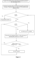
- Figure 1 illustrates a flowchart of a method for controlling rotational speed avoidance for a wind turbine according to an exemplary embodiment of the present disclosure.
- step S 10 in response to receiving an instruction for limited-power operation, an upper limit of power required by the instruction is determined.
- the instruction for limited-power operation may be received from a central controller at a wind farm or a cluster controller at a wind farm.
- the wind farm may issue an instruction for limited-power operation to the wind turbine due to electricity rationing or other reasons.
- step S20 it is determined whether the required upper limit of power is in a power avoidance range corresponding to a rotational speed avoidance range.
- the power avoidance range represents a power range corresponding to the rotational speed avoidance range.
- an upper boundary value of the power avoidance range is power determined based on an upper boundary value of the rotational speed avoidance range
- the lower boundary value of the power avoidance range is power determined based on a lower boundary value of the rotational speed avoidance range, where, each of the rotational speed avoidance range and the power avoidance range is an open interval.
- Control for rotational speed avoidance / passing through rotational speed is a control function/strategy for the rotational speed of a generator, and specifically refers to that, by controlling an electromagnetic torque of a converter of the wind turbine and the rotational speed of a rotor of the generator, the wind turbine is enabled to quickly pass through a certain rotational speed range (i.e., rotational speed avoidance range) in a power generation process, to prevent the rotational speed from staying in the rotational speed range for a long time, resulting in resonance of the wind turbine, increased loads or other issues. That is, the rotational speed avoidance range mentioned in the present disclosure may be set by a consideration of resonance, load reduction or other conditions, which is not limited in the present disclosure.
- wind energy is captured by an impeller of the wind turbine, and an energy conversion unit is formed by the generator and the converter, and converts the wind energy into electrical energy and transmits the electrical energy to the grid.
- the generator includes a stator and a rotor mechanically connected to the impeller.
- the converter is electrically coupled to a stator winding.
- the generator is a permanent magnet generator with magnet steel being provided in the rotor.
- the wind turbine is a direct-drive type wind turbine, the converter is a full-power converter, and the electric energy converted from the wind energy is all fed into the grid.
- a controller of the wind turbine collects the wind speed and a current rotational speed of the generator and transmits an electromagnetic torque control signal to the converter for controlling the current in the stator winding of the generator, to control the rotational speed of the rotor of the generator.
- an aerodynamic torque T a 0.5 ⁇ C q ⁇ R 3 V 2
- an aerodynamic torque T a is direct proportional to a square of the wind speed V, where ⁇ represents the air density of an external environment where the wind turbine locates, C q represents a torque coefficient of the wind turbine, and R represents the radius of the impeller.
- the wind turbine may control a pitch angle of each blade through a pitch system, to limit the energy of a wind flow absorbed by the impeller, and then adjust the aerodynamic torque.
- the generator may control an electromagnetic torque T e of the generator while performing the electrical energy conversion.
- a differential of the rotational speed of the generator is related to a difference between the aerodynamic torque T a and the electromagnetic torque T e , where J1 represents a moment of inertia, and w represents an angular velocity. Therefore, the entire wind turbine may adjust the aerodynamic torque T a and the electromagnetic torque T e through a pitch mechanism to control the rotational speed of the wind turbine.
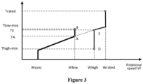
- Figure 3 illustrates a rotational speed-electromagnetic torque operation curve of the generator, in which the ordinate represents the electromagnetic torque and the abscissa represents the rotational speed.
- the rotational speed is between Wsync and Wrated, and (Wlow, Whigh) is the rotational speed avoidance range, Wlow is the lower boundary value of the rotational speed avoidance range, and Whigh is the upper boundary value of the rotational speed avoidance range, that is, the wind turbine cannot stay in the rotational speed range for a long time.
- Tlow-max and Thigh-min correspond to requirements for controlling the electromagnetic torque at two rotational speeds of Wlow and Whigh respectively.
- the rotational speed is controlled at Wlow. If the wind speed increases in this case, in order to maintain the rotational speed at Wlow, the electromagnetic torque increases continually from TA until reaching Tlow-max (that is, reaching point B). After the rotational speed stays at the point B for T1 seconds, the rotational speed is increased at a speed of V1 rad/s until the rotational speed reaches Whigh, that is, an operating state reaches point E. If the wind speed further increases in this case, the rotational speed continues to increase upward.
- the rotational speed cannot continue to decrease according to the requirements for controlling rotational speed avoidance.
- the rotational speed is maintained at Whigh in this case. If the wind speed decreases in this case, in order to maintain the rotational speed at Whigh, the electromagnetic torque decreases continually from TE until reaching Thigh-min (that is, reaching point D). After staying at the point D for T2 seconds, the rotational speed is reduced at a speed of V2 rad/s to jump to the point A.
- Wlow and Whigh may be determined based on a design frequency (e.g., an inherent frequency of structural components including the tower) of the wind turbine.
- the upper boundary value of the power avoidance range is a product of the upper boundary value (i.e., Whigh) of the rotational speed avoidance range and a first predetermined electromagnetic torque (i.e., Tlow-max), where the first predetermined electromagnetic torque is an electromagnetic torque that is to be kept before passing through the rotational speed avoidance range from a low rotational speed to a high rotational speed.
- the lower boundary value of the power avoidance range is a product of the lower boundary value (i.e., Wlow) of the rotational speed avoidance range and a second predetermined electromagnetic torque (i.e., TA), where the second predetermined electromagnetic torque is an electromagnetic torque when the wind turbine just reaches the lower boundary value of the rotational speed avoidance range.
- step S30 is performed to set the maximum allowable power of the wind turbine as the lower boundary value of the power avoidance range.
- the power of the wind turbine is not allowed to exceed the lower boundary value of the power avoidance range.
- feedback may be given to an object that transmits the instruction for limited-power operation, for example, information that the maximum allowable power of the wind turbine is set as the lower boundary value of the power avoidance range may be fed back.
- step S40 is performed to set the maximum allowable power of the wind turbine as the required upper limit of power. In other words, the power of the wind turbine is not allowed to exceed the required upper limit of power.
- the method for controlling rotational speed avoidance for a wind turbine further includes: identifying whether there is an abnormality of repeatedly passing through the rotational speed avoidance range in the wind turbine, based on statistical information about the rotational speed of the generator being in the rotational speed avoidance range, where, in a case that it is determined that there is an abnormality, step S20 is performed.
- the statistical information about the rotational speed of the generator being in the rotational speed avoidance range may be statistical information that may be used to judge whether the rotational speed of the generator is often in or frequently enters the rotational speed avoidance range.
- the statistical information about the rotational speed of the generator being in the rotational speed avoidance range may include: a statistical duration about the rotational speed of the generator being in the rotational speed avoidance range and/or a statistical counting that the rotational speed enters the rotational speed avoidance range.
- a rotational speed avoidance condition of the wind turbine may refer to a condition in which the rotational speed of the generator enters or is in the rotational speed avoidance range.
- the statistical information about the rotational speed of the generator being in the rotational speed avoidance range shows that the rotational speed is often in or frequently enters the rotational speed avoidance range exceeding a certain degree, it may be determined that there is an abnormality of repeatedly passing through the rotational speed avoidance range in the wind turbine.
- a range may be reserved at both ends of the rotational speed avoidance range, and it is considered that the rotational speed being in the reserved range is a normal operation condition.
- the statistical information about the rotational speed of the generator being in the rotational speed avoidance range may include: the statistical duration in which the rotational speed of the generator is in a first predetermined range in the rotational speed avoidance range and/or the statistical number of times that the rotational speed enters the first predetermined range.
- the first predetermined range may be: (Wlow+We1, Whigh-We2).
- the rotational speed of the generator may or may not be equal to the rotational speed of the impeller.
- the step of identifying whether there is an abnormality of repeatedly passing through the rotational speed avoidance range in the wind turbine based on a statistical duration in which a rotational speed of a generator is in the rotational speed avoidance range may include: determining, based on operation data in a historical operation period of the wind turbine, a proportion of a rotational speed avoidance duration corresponding to each of time intervals in the historical operation period, where the proportion of a rotational speed avoidance duration corresponding to each of time intervals is a proportion of a total duration, in which the rotational speed is in a first predetermined range in the rotational speed avoidance range within the time interval, to a predetermined duration; and determining that there is an abnormality of repeatedly passing through the rotational speed avoidance range in the wind turbine, in a case that a total number of time intervals in which a proportion of the rotational speed avoidance duration exceeds a predetermined standard proportion in the historical operation period, exceeds a first predetermined number, where, each of time intervals has a length of
- the operation data in the historical operation period may be divided into M groups of operation data in an interval of the predetermined duration, where each group of operation data includes N rotational speeds of the generator collected at N consecutive sampling time points (that is, N rotational speeds are collected by collecting one rotational speed at each sampling time point).
- a ratio of the number of rotational speeds in the first predetermined range in the N rotational speeds of each group to N is determined as the proportion of the rotational speed avoidance duration corresponding to the corresponding time range, where, M is an integer greater than 1, and N is an integer greater than 1. It should be understood that each group corresponds to a time interval, and different groups correspond to different time intervals.
- the predetermined standard proportion may indicate that a proportion of the total duration of the rotational speed in the rotational speed avoidance range to the predetermined duration within the predetermined duration, in a case of a normal rotational speed avoidance jump. Therefore, the proportion of the rotational speed avoidance duration corresponding to any time interval exceeding the proportion of normality indicates that the rotational speed avoidance in the time interval is abnormal.
- the predetermined standard proportion may be determined based on at least one of the following: a jump-up duration (i.e., (Whigh-Wlow)/V1) required for the wind turbine to pass through the rotational speed avoidance range from a low rotational speed to a high rotational speed, a jump-down duration (i.e.. (Whigh-Wlow)/V2) required to pass through the rotational speed avoidance range from a high rotational speed to a low rotational speed, a predetermined number of times that the rotational speed avoidance range can be normally passed through within the predetermined duration, and a length of the predetermined duration.
- a jump-up duration i.e., (Whigh-Wlow)/V1
- a jump-down duration i.e. (Whigh-Wlow)/V2
- a predetermined number of times that the rotational speed avoidance range can be normally passed through within the predetermined duration a length of the predetermined duration.
- the predetermined standard proportion may be Ks: T max *I*J/L, where, T max represents a maximum among the jump-up duration and the jump-down duration, I represents a redundancy coefficient, J represents the predetermined number of times that the rotational speed avoidance range can be normally passed through within the predetermined duration, and L represents the length of the predetermined duration.
- the number of times that the rotational speed avoidance range can be normally passed through within the predetermined duration may be determined based on at least one of actual operation conditions, simulation, and human experience. For example, in a case that the length of the predetermined duration is 20 minutes, the number of times that the rotational speed avoidance range can be normally passed through within the predetermined duration may be 10.
- a redundancy coefficient I is added. For example, I may be set to a value between 1.1 and 1.5.
- Figure 4 illustrates a flowchart of a method for determining a proportion of a rotational speed avoidance duration corresponding to each of time intervals in a historical operating period according to an exemplary embodiment of the present disclosure.
- step S101 the operation data in the historical operation period of the wind turbine is acquired, where the operation data includes the rotational speed.
- the operation data in the historical operation period may be divided into M groups of operation data in an interval of the predetermined duration.
- the historical operation period is divided every predetermined duration, and the obtained operational data for each of time intervals forms a group of operational data.
- Each group of operation data includes N rotational speeds of the generator collected at N consecutive sampling time points (i.e., N operation points), and the N rotational speeds are ranked in an order of corresponding sampling time points. It should be understood that N depends on the length of the predetermined duration and a sampling period of operation data.
- the historical operation period may be the latest month
- the predetermined duration may be a value from 10min to 30min.
- step S103 it is judged whether i is less than or equal to M, where the initial value of i is 1.
- step S104 is performed to judge whether j is less than or equal to N, where the initial value of j is 1.
- step S106 is performed to judge whether the extracted j-th rotational speed w ij in the i-th group of operating data is greater than (Wlow+We1) and less than (Whigh-We2).
- step S106 In a case that it is determined in step S106 that w ij ⁇ (Wlow+We1), or w ij ⁇ (Whigh-We2), the process returns to step S104.
- step S109 is performed to record all Ki, that is, record K1, K2, K3, ..., KM.
- each Ki is the proportion of the rotational speed avoidance duration corresponding to each of time intervals in the historical operation period.
- the rotational speed avoidance range is (9, 11.5).
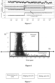
- Figure 5 illustrates a situation that the rotational speed of the wind turbine is frequently in the rotational speed avoidance range, which will result in abnormal resonance of the wind turbine, overloaded loads and other problems. After analysis, it is known in the present disclosure that this situation is generally due to the fact that if an instruction for limited power is received from outside, the wind turbine controls a current rotational speed of the generator based on the limited power.
- the rotational speed corresponding to a power limit is just within the rotational speed avoidance range, as shown in Figure 5 , the power limit is 1MW, and the corresponding rotational speed is 10.5 rpm, causing a rotational speed avoidance function to fail, which causes that the wind turbine operates in the rotational speed avoidance range for a long time, and the situation of rotational speed avoidance is abnormal.
- the abnormal evaluation of wind turbines repeatedly passing through the rotational speed avoidance range is still blank.
- the main reason lies in that due to the uncertainty of the above reasons, the abnormality is difficult to find during a prototype test, especially electricity rationing at the wind farm has great uncertainty.
- the abnormality of repeatedly passing through the rotational speed avoidance range often brings the following two problems: 1. the wind turbine is operating in the rotational speed avoidance range for a long time, and in a case that the vibration increases to a corresponding protection threshold, a shutdown failure occurs; 2.
- the wind turbine is operating in the rotational speed avoidance range for a long time or a short time, but the vibration does not reach the corresponding protection threshold, the impact (for example, a shutdown failure) may not be realized in the short term, however, loss of power generation and loss of fatigue life of components occur after the long-term accumulation, resulting in the expense of loss of power generation and component damage, and it is difficult to find that the above problem is due to the abnormal rotational speed avoidance.
- the rotational speed avoidance is abnormal and the reason for the abnormal rotational speed avoidance is that a maximum operating range of the rotational speed determined by the wind turbine based on the instruction for limited-power overlaps with the rotational speed avoidance range. Therefore, it is required to perform steps S20 to S30, to avoid the abnormality of the rotational speed avoidance for the wind turbine as much as possible.
- the time interval corresponding to the limited-power operation state refers to a time interval in which the wind turbine is in the limited-power operation state.
- the predetermined wind speed range is a wind speed range in the vicinity of a wind speed range corresponding to the rotational speed avoidance range.
- the wind speed range corresponding to the rotational speed avoidance range is a wind speed range in which the rotational speed enters the rotational speed avoidance range.
- the wind speed range in the vicinity of the wind speed range corresponding to the rotational speed avoidance range may be a wind speed range including the wind speed range corresponding to the rotational speed avoidance range, the lower boundary value of the wind speed range is smaller than the lower boundary value of the wind speed range corresponding to the rotational speed avoidance range by a first predetermined value, and the upper boundary value of the wind speed range is greater than the upper boundary value of the wind speed range corresponding to the rotational speed avoidance range by a second predetermined value.
- the time interval corresponding to the predetermined wind speed range refers to a time interval in which an ambient wind speed of the wind turbine is in the predetermined wind speed range.
- Figure 6 illustrates the distribution of the proportion Ki of the rotational speed avoidance duration corresponding to different time intervals of the wind turbine.
- the abscissa in Figure 6 represents the wind speed, and the ordinate represents the value of Ki.
- the predetermined standard proportion Ks is 0.2, and each point represents the proportion of the rotational speed avoidance duration corresponding to the wind turbine in one time interval. Therefore, the point where the proportion of the rotational speed avoidance duration exceeds 0.2 is an abnormal point, otherwise is a normal point.
- the set of points in Figure 6 has an apparent columnar structure, and the highest point is in the vicinity of the wind speed of 6m/s which corresponds to points of wind speed corresponding to the rotational speed avoidance range.
- the energy provided by the wind keeps the rotational speed between the upper boundary value and the lower boundary value of the rotational speed avoidance range, namely, if the wind speed is relatively small, the rotational speed stays at the lower boundary value for a long time, and if the wind speed is relatively large, the rotational speed stays at the upper boundary value for a long time.
- the abnormal points are distributed in a columnar shape, and the maximum Ki value of the abnormal points reaches 1. That is, in some time intervals, the rotational speed of the wind turbine is in the rotational speed avoidance range for a long time.
- the Ki value of some abnormal points is large
- the abnormal rotational speed avoidance for the wind turbine is caused by the limited-power operation.
- the power of the wind turbine is related to the rotational speed. The higher the power generally corresponds to the higher the rotational speed of the wind turbine.
- a set value of rotational speed corresponding to the required power limit is retrieved in the limited-power operation, and is used as a control target of the rotational speed.
- the rotational speed avoidance situation is abnormal. Therefore, the above circumstance can be improved by performing steps S20 to S30.
- the present disclosure is enabled to quickly and accurately assess whether there is an abnormality in the rotational speed avoidance for the wind turbine, and further perform corresponding processing for the cause of the abnormal situation of rotational speed avoidance in combination with analysis and diagnosis of basic causes, in order to jump out the abnormality and return to a normal operating state of the wind turbine, thus avoiding further vibration exceeding the limit and increased load.
- Figure 7 illustrates a block diagram of an apparatus for controlling rotational speed avoidance for a wind turbine according to an exemplary embodiment of the present disclosure.
- the apparatus for controlling rotational speed avoidance for a wind turbine includes: a determining unit 10, a judging unit 20, and a setting unit 30.
- the determining unit 10 is configured to determine, in response to receiving an instruction for limited-power operation, an upper limit of power required by the instruction.
- the judging unit 20 is configured to judge whether the required upper limit of power is in a power avoidance range corresponding to a rotational speed avoidance range.
- An upper boundary value of the power avoidance range is power determined based on an upper boundary value of the rotational speed avoidance range
- a lower boundary value of the power avoidance range is power determined based on a lower boundary value of the rotational speed avoidance range, where each of the rotational speed avoidance range and the power avoidance range is an open interval.
- the setting unit 30 is configured to set maximum allowable power of the wind turbine as the lower boundary value of the power avoidance range in a case that the required upper limit of power is in the power avoidance range.
- the setting unit 30 may set the maximum allowable power of the wind turbine to the required upper limit of power in a case that the required upper limit of power is not in the power avoidance range.
- the upper boundary value of the power avoidance range is a product of the upper boundary value of the rotational speed avoidance range and a first predetermined electromagnetic torque
- the lower boundary value of the power avoidance range is a product of the lower boundary value of the rotational speed avoidance range and a second predetermined electromagnetic torque.
- the first predetermined electromagnetic torque is an electromagnetic torque value that is to be kept before passing through the rotational speed avoidance range from a low rotational speed to a high rotational speed
- the second predetermined electromagnetic torque is an electromagnetic torque value when the wind turbine reaches the lower boundary value of the rotational speed avoidance range.
- the apparatus further includes: an abnormality identifying unit (not shown).
- the abnormality identifying unit is configured to identify whether there is an abnormality of repeatedly passing through the rotational speed avoidance range for the wind turbine based on statistical information about a rotational speed of a generator being in the rotational speed avoidance range.
- the judging unit 20 determines whether the required upper limit of power is in the power avoidance range corresponding to the rotational speed avoidance range.
- the statistical information about the rotational speed of the generator being in the rotational speed avoidance range may include: a statistical duration in which the rotational speed of the generator is in the rotational speed avoidance range and/or a statistical number of times that the rotational speed enters the rotational speed avoidance range.
- the abnormality identifying unit may determine, based on operation data in a historical operation period of the wind turbine, a proportion of a rotational speed avoidance duration corresponding to each of time intervals in the historical operation period; and determine that there is an abnormality of repeatedly passing through the rotational speed avoidance range for the wind turbine, in a case that a total number of time intervals in which a proportion of the rotational speed avoidance duration exceeds a predetermined standard proportion in the historical operation period, exceeds a first predetermined number.
- the proportion of a rotational speed avoidance duration corresponding to each of time intervals is a proportion of a total duration, in which the rotational speed is in a first predetermined range in the rotational speed avoidance range within the time interval, to a predetermined duration.
- Each of time intervals has a length of the predetermined duration.
- the abnormality identifying unit may determine that there is an abnormality of repeatedly passing through the rotational speed avoidance range for the wind turbine, in a case that a total number of time intervals corresponding to a limited-power operation state and in which a proportion of the rotational speed avoidance duration exceeds a predetermined standard proportion in the historical operation period, exceeds a second predetermined number.
- the abnormality identifying unit may determine that there is an abnormality of repeatedly passing through the rotational speed avoidance range for the wind turbine, in a case that a total number of time intervals corresponding to a predetermined wind speed range and in which a proportion of the rotational speed avoidance duration exceeds a predetermined standard proportion in the historical operation period, exceeds a third predetermined number, where, the predetermined wind speed range is a wind speed range in the vicinity of a wind speed range corresponding to the rotational speed avoidance range.
- the abnormality identifying unit may divide the operation data in the historical operation period into M groups of operation data in an interval of the predetermined duration, where each group of operation data includes N rotational speeds of the generator collected at N consecutive sampling time points; and determine a ratio of the number of rotational speeds in the first predetermined range in the N rotational speeds of each group to N as the proportion of the rotational speed avoidance duration corresponding to the respective each interval, where, M is an integer greater than 1, and N is an integer greater than 1.
- the predetermined standard proportion may be determined based on at least one of the following: a jump-up duration required for the wind turbine to pass through the rotational speed avoidance range from a low rotational speed to a high rotational speed, a jump-down duration required to pass through the rotational speed avoidance range from a high rotational speed to a low rotational speed, a predetermined number of times that the rotational speed avoidance range can be normally passed through within the predetermined duration, and a length of the predetermined duration.
- the predetermined standard proportion may be T max *I*J/L, where, T max represents a maximum among the jump-up duration and the jump-down duration, I represents a redundancy coefficient, J represents the predetermined number of times that the rotational speed avoidance range can be normally passed through within the predetermined duration, and L represents the length of the predetermined duration.
- each of units in the apparatus for controlling rotational speed avoidance for a wind turbine may be implemented as hardware components and/or software components.
- Those skilled in the art may implement the various apparatus based on the defined processing to be performed by each apparatus using a field programmable gate array (FPGA) or an application specific integrated circuit (ASIC), for example.
- FPGA field programmable gate array
- ASIC application specific integrated circuit
- the wind turbine includes a generator, a converter, a data collection module (not shown in the figure) and a controller.
- the generator includes a stator and a rotor mechanically connected to an impeller; the converter is electrically coupled to a stator winding; the data collection module is configured to collect a rotational speed of the rotor of the generator; and the controller is configured to set an electromagnetic torque parameter of the converter to control the current in the stator winding, thereby controlling the rotational speed of the rotor of the generator.
- the controller is configured to perform the method for controlling rotational speed avoidance for a wind turbine according to the foregoing exemplary embodiments.
- the data collection module may include a rotational speed sensor.
- the data collection module may further be configured to collect information such as electromagnetic torque and ambient wind speed of the wind turbine.
- the wind turbine includes a generator, a converter, a data collection module (not shown in the figure) and a controller.
- the generator includes a stator and a rotor mechanically connected to an impeller; the converter is electrically coupled to a stator winding; the data collection module is configured to collect a rotational speed of the rotor of the generator; and the controller is configured to set an electromagnetic torque parameter of the converter to control the current in the stator winding, thereby controlling the rotational speed of the rotor of the generator.
- the controller includes the apparatus for controlling rotational speed avoidance for a wind turbine according to the forgoing exemplary embodiments.
- a computer-readable storage medium storing computer programs thereon is provided according to an exemplary embodiment of the present disclosure.
- the computer programs when being executed by a processor, cause the processor to implement the method for controlling rotational speed avoidance for a wind turbine according to the foregoing exemplary embodiments.
- the computer-readable storage medium is any data storage device that can store data read by a computer system. Examples of the computer-readable storage medium include a read-only memory, a random-access memory, read-only optical disks, magnetic tapes, floppy disks, optical data storage devices, and carrier waves (such as data transmission over the Internet via wired or wireless transmission paths).
Landscapes
- Engineering & Computer Science (AREA)
- Life Sciences & Earth Sciences (AREA)
- Sustainable Development (AREA)
- Sustainable Energy (AREA)
- Chemical & Material Sciences (AREA)
- Combustion & Propulsion (AREA)
- Mechanical Engineering (AREA)
- General Engineering & Computer Science (AREA)
- Power Engineering (AREA)
- Wind Motors (AREA)
- Control Of Eletrric Generators (AREA)
Claims (13)
- Verfahren zur Steuerung der Drehzahlvermeidung für eine Windkraftanlage, Folgendes umfassend:Bestimmen (S10) einer Obergrenze der durch die Instruktion erforderlichen Leistung als Reaktion auf den Empfang einer Instruktion für einen Vorgang mit begrenzter Leistung;Identifizieren, ob eine Anomalie vorliegt, wenn die Windkraftanlage wiederholt den Bereich zur Drehzahlvermeidung durchläuft, basierend auf statistischen Informationen über eine Drehzahl eines Generators, die sich im Bereich zur Drehzahlvermeidung befindet;Beurteilen (S20), ob die geforderte Obergrenze der Leistung in einem Leistungsvermeidungsbereich liegt, der einem Drehzahlvermeidungsbereich entspricht, wenn eine Anomalie vorliegt;Einstellen (S30) der maximal zulässigen Leistung der Windkraftanlage als unterer Grenzwert des Leistungsvermeidungsbereichs für den Fall, dass die geforderte Obergrenze der Leistung im Leistungsvermeidungsbereich liegt,wobei ein oberer Grenzwert des Leistungsvermeidungsbereichs eine Leistung ist, die basierend auf einem oberen Grenzwert des Drehgeschwindigkeitsvermeidungsbereichs bestimmt wird, und der untere Grenzwert des Leistungsvermeidungsbereichs eine Leistung ist, die basierend auf einem unteren Grenzwert des Drehzahlvermeidungsbereichs bestimmt wird,wobei sowohl der Drehzahlvermeidungsbereich als auch der Leistungsvermeidungsbereich ein offenes Intervall ist,wobei der obere Grenzwert des Leistungsvermeidungsbereichs ein Produkt aus dem oberen Grenzwert des Drehzahlvermeidungsbereichs und einem ersten vorgegebenen elektromagnetischen Drehmoment ist,wobei der untere Grenzwert des Leistungsvermeidungsbereichs ein Produkt aus dem unteren Grenzwert des Drehzahlvermeidungsbereichs und einem zweiten vorgegebenen elektromagnetischen Drehmoment ist,wobei das erste vorgegebene elektromagnetische Drehmoment ein elektromagnetisches Drehmoment ist, das vor dem Durchlaufen des Drehzahlvermeidungsbereichs von einer niedrigen Drehzahl zu einer hohen Drehzahl gehalten werden soll, undwobei das zweite vorgegebene elektromagnetische Drehmoment ein elektromagnetisches Drehmoment ist, wenn die Windkraftanlage den unteren Grenzwert des Drehzahlvermeidungsbereichs erreicht.
- Verfahren nach Anspruch 1, wobei das Verfahren ferner umfasst:
Einstellen (S40) der maximal zulässigen Leistung der Windkraftanlage als geforderte Leistungsobergrenze für den Fall, dass die geforderte Leistungsobergrenze nicht im Leistungsvermeidungsbereich liegt. - Verfahren nach Anspruch 1, wobei die statistische Information darüber, dass sich die Drehzahl des Generators im Drehzahlvermeidungsbereich befindet, Folgendes umfasst: eine statistische Dauer, in der sich die Drehzahl des Generators im Drehzahlvermeidungsbereich befindet, und/oder eine statistische Anzahl von Malen, die die Drehzahl in den Drehzahlvermeidungsbereich eintritt.
- Verfahren nach Anspruch 3, wobei der Schritt des Erkennens, ob es eine Anomalie gibt, wenn die Windkraftanlage wiederholt den Bereich zur Drehzahlvermeidung durchläuft, basierend auf der statistischen Dauer, in der die Drehzahl des Generators im Drehzahlvermeidungsbereich liegt, Folgendes umfasst:Bestimmen, basierend auf Betriebsdaten in einer historischen Betriebsperiode der Windkraftanlage, eines Anteils einer Drehzahlvermeidungsdauer, die jedem der Zeitintervalle in der historischen Betriebsperiode entspricht, wobei der Anteil einer Drehzahlvermeidungsdauer, der jedem der Zeitintervalle entspricht, ein Anteil einer Gesamtdauer, in der die Drehzahl in einem ersten vorgegebenen Bereich in dem Drehzahlvermeidungsbereich innerhalb des Zeitintervalls liegt, an einer vorgegebenen Dauer ist; undBestimmen, dass eine Anomalie des wiederholten Durchlaufens des Drehzahlvermeidungsbereichs in der Windkraftanlage vorliegt, wenn eine Gesamtzahl von Zeitintervallen, in denen ein Anteil der Drehzahlvermeidungsdauer einen vorgegebenen Standardanteil in der historischen Betriebsperiode überschreitet, eine erste vorgegebene Zahl überschreitet,wobei jedes der Zeitintervalle eine Länge der vorgegebenen Dauer aufweist.
- Verfahren nach Anspruch 4, wobei der Schritt der Feststellung, dass eine Anomalie des wiederholten Durchlaufens des Drehzahlvermeidungsbereichs für die Windkraftanlage vorliegt, Folgendes umfasst:Bestimmen, dass eine Anomalie des wiederholten Durchlaufens des Drehzahlvermeidungsbereichs für die Windkraftanlage vorliegt, wenn eine Gesamtzahl von Zeitintervallen, die einem leistungsbegrenzten Betriebszustand entsprechen und in denen ein Anteil der Drehzahlvermeidungsdauer einen vorgegebenen Standardanteil in der historischen Betriebsperiode überschreitet, eine zweite vorgegebene Zahl überschreitet, oderBestimmen, dass eine Anomalie des wiederholten Durchlaufens des Drehzahlvermeidungsbereichs für die Windkraftanlage vorliegt, wenn eine Gesamtzahl von Zeitintervallen, die einem vorgegebenen Windgeschwindigkeitsbereich entsprechen und in denen ein Anteil der Drehzahlvermeidungsdauer einen vorgegebenen Standardanteil in der historischen Betriebsperiode überschreitet, eine dritte vorgegebene Zahl überschreitet,wobei der vorgegebene Windgeschwindigkeitsbereich ein Windgeschwindigkeitsbereich ist, der in der Nähe eines Windgeschwindigkeitsbereichs liegt, der dem Drehzahlvermeidungsbereich entspricht.
- Verfahren nach Anspruch 4, wobei der Schritt des Bestimmens, basierend auf Betriebsdaten in einer historischen Betriebsperiode der Windkraftanlage, eines Anteils einer Drehzahlvermeidungsdauer, die jedem der Zeitintervalle in der historischen Betriebsperiode entspricht, Folgendes umfasst:Aufteilen der Betriebsdaten in der historischen Betriebsperiode in M Gruppen von Betriebsdaten in einem Intervall der vorgegebenen Dauer, wobei jede Gruppe von Betriebsdaten N Drehzahlen des Generators umfasst, die an N aufeinanderfolgenden Abtastzeitpunkten gesammelt wurden; undBestimmen eines Verhältnisses der Anzahl der Drehzahlen im ersten vorgegebenen Bereich in den N Drehzahlen jeder Gruppe zu N als Anteil der Drehzahlvermeidungsdauer, die dem entsprechenden Zeitintervall entspricht,wobei M eine ganze Zahl größer als 1 ist und N eine ganze Zahl größer als 1 ist.
- Verfahren nach Anspruch 4, wobei der vorgegebene Standardanteil basierend auf mindestens einem von einer Anstiegsdauer, die erforderlich ist, damit die Windkraftanlage den Drehzahlvermeidungsbereich von einer niedrigen Drehzahl zu einer hohen Drehzahl durchläuft, einer Reduzierungsdauer, die erforderlich ist, um den Drehzahlvermeidungsbereich von einer hohen Drehzahl zu einer niedrigen Drehzahl zu durchlaufen, einer vorgegebenen Anzahl von Malen, die der Drehzahlvermeidungsbereich normalerweise innerhalb der vorgegebenen Dauer durchlaufen kann, und einer Länge der vorgegebenen Dauer bestimmt wird.
- Verfahren nach Anspruch 7, wobei der vorbestimmte Standardanteil Tmax*I*J/L ist, wobei Tmax ein Maximum zwischen der Anstiegsdauer und der Reduzierungsdauer darstellt, I einen Redundanzkoeffizienten darstellt, J die vorgegebene Anzahl von Malen darstellt, die der Drehzahlvermeidungsbereich normalerweise innerhalb der vorgegebenen Dauer durchlaufen kann, und L die Länge der vorgegebenen Dauer darstellt.
- Vorrichtung zur Steuerung der Drehzahlvermeidung für eine Windkraftanlage, Folgendes umfassend:eine Bestimmungseinheit (10), die konfiguriert ist, um eine Obergrenze der durch die Instruktion erforderlichen Leistung als Reaktion auf den Empfang einer Instruktion für einen Vorgang mit begrenzter Leistung zu bestimmen;eine Anomalie-Identifizierungseinheit, die konfiguriert ist, um zu identifizieren, ob eine Anomalie vorliegt, wenn die Windkraftanlage wiederholt den Bereich zur Drehzahlvermeidung durchläuft, basierend auf statistischen Informationen über eine Drehzahl eines Generators, die sich im Bereich zur Drehzahlvermeidung befindet;eine Beurteilungseinheit (20), die konfiguriert ist, um zu beurteilen, ob die geforderte Obergrenze der Leistung in einem Leistungsvermeidungsbereich liegt, der einem Drehzahlvermeidungsbereich entspricht, wenn eine Anomalie vorliegt;eine Einstelleinheit (30), die so konfiguriert ist, dass sie die maximal zulässige Leistung der Windkraftanlage als unteren Grenzwert des Leistungsvermeidungsbereichs für den Fall festlegt, dass die geforderte Obergrenze der Leistung im Leistungsvermeidungsbereich liegt,wobei ein oberer Grenzwert des Leistungsvermeidungsbereichs eine Leistung ist, die basierend auf einem oberen Grenzwert des Drehgeschwindigkeitsvermeidungsbereichs bestimmt wird, und der untere Grenzwert des Leistungsvermeidungsbereichs eine Leistung ist, die basierend auf einem unteren Grenzwert des Drehzahlvermeidungsbereichs bestimmt wird,wobei sowohl der Drehzahlvermeidungsbereich als auch der Leistungsvermeidungsbereich ein offenes Intervall ist,wobei der obere Grenzwert des Leistungsvermeidungsbereichs ein Produkt aus dem oberen Grenzwert des Drehzahlvermeidungsbereichs und einem ersten vorgegebenen elektromagnetischen Drehmoment ist,wobei der untere Grenzwert des Leistungsvermeidungsbereichs ein Produkt aus dem unteren Grenzwert des Drehzahlvermeidungsbereichs und einem zweiten vorgegebenen elektromagnetischen Drehmoment ist,wobei das erste vorgegebene elektromagnetische Drehmoment ein elektromagnetisches Drehmoment ist, das vor dem Durchlaufen des Drehzahlvermeidungsbereichs von einer niedrigen Drehzahl zu einer hohen Drehzahl gehalten werden soll, undwobei das zweite vorgegebene elektromagnetische Drehmoment ein elektromagnetisches Drehmoment ist, wenn die Windkraftanlage den unteren Grenzwert des Drehzahlvermeidungsbereichs erreicht.
- Windkraftanlage, umfassend:einen Generator, der einen Stator und einen Rotor umfasst, die mechanisch mit einem Laufrad verbunden sind;einen Wandler, der elektrisch an eine Statorwicklung gekoppelt ist;ein Datenerfassungsmodul, das konfiguriert ist, um eine Drehzahl des Rotors des Generators zu erfassen; undeine Steuerung, die konfiguriert ist, um einen elektromagnetischen Drehmomentparameter des Wandlers festzulegen, um die Drehzahl des Generators zu steuern, und konfiguriert ist, um das Verfahren zur Steuerung der Drehzahlvermeidung nach einem der Ansprüche 1 bis 8 durchzuführen.
- Windkraftanlage nach Anspruch 10, wobei der Generator ein Permanentmagnetgenerator ist und die Windkraftanlage eine direkt angetriebene Windkraftanlage ist.
- Windkraftanlage, umfassend:einen Generator, der einen Stator und einen Rotor umfasst, die mechanisch mit einem Laufrad verbunden sind;einen Wandler, der elektrisch an eine Statorwicklung gekoppelt ist;ein Datenerfassungsmodul, das konfiguriert ist, um eine Drehzahl des Rotors des Generators zu erfassen; undeine Steuerung, die konfiguriert ist, um einen elektromagnetischen Drehmomentparameter des Wandlers festzulegen, um die Drehzahl des Generators zu steuern, wobei die Steuerung die Vorrichtung zur Steuerung der Drehzahlvermeidung nach Anspruch 9 umfasst.
- Computerlesbares Speichermedium, auf dem Computerprogramme gespeichert sind, wobei die Computerprogramme, wenn sie von einem Prozessor ausgeführt werden, den Prozessor veranlassen, das Verfahren zum Steuern der Drehzahlvermeidung für eine Windkraftanlage nach einem der Ansprüche 1 bis 8 durchzuführen.
Applications Claiming Priority (2)
| Application Number | Priority Date | Filing Date | Title |
|---|---|---|---|
| CN202010597078.1A CN113847195B (zh) | 2020-06-28 | 2020-06-28 | 风力发电机组及其避转速控制方法、装置 |
| PCT/CN2021/084035 WO2022001250A1 (zh) | 2020-06-28 | 2021-03-30 | 风力发电机组及其避转速控制方法、装置 |
Publications (4)
| Publication Number | Publication Date |
|---|---|
| EP4130463A1 EP4130463A1 (de) | 2023-02-08 |
| EP4130463A4 EP4130463A4 (de) | 2023-10-04 |
| EP4130463B1 true EP4130463B1 (de) | 2025-01-01 |
| EP4130463C0 EP4130463C0 (de) | 2025-01-01 |
Family
ID=78972562
Family Applications (1)
| Application Number | Title | Priority Date | Filing Date |
|---|---|---|---|
| EP21833227.8A Active EP4130463B1 (de) | 2020-06-28 | 2021-03-30 | Windturbinengeneratorsystem und verfahren und vorrichtung zur steuerung der drehzahlvermeidung dafür |
Country Status (10)
| Country | Link |
|---|---|
| US (1) | US12224699B2 (de) |
| EP (1) | EP4130463B1 (de) |
| CN (1) | CN113847195B (de) |
| AU (1) | AU2021303191B2 (de) |
| BR (1) | BR112022024196A2 (de) |
| CA (1) | CA3180650A1 (de) |
| CL (1) | CL2022003347A1 (de) |
| ES (1) | ES3006008T3 (de) |
| WO (1) | WO2022001250A1 (de) |
| ZA (1) | ZA202212229B (de) |
Families Citing this family (3)
| Publication number | Priority date | Publication date | Assignee | Title |
|---|---|---|---|---|
| CN116696668A (zh) * | 2022-02-28 | 2023-09-05 | 金风科技股份有限公司 | 一种风力发电机的振动控制方法和相关装置 |
| CN116146417B (zh) * | 2023-04-19 | 2023-08-11 | 中车山东风电有限公司 | 风力发电机组转速被动动态区间穿越方法、装置、设备 |
| CN116517769B (zh) * | 2023-05-22 | 2024-07-05 | 北京金风科创风电设备有限公司 | 风力发电机组及其停机控制方法及装置 |
Family Cites Families (15)
| Publication number | Priority date | Publication date | Assignee | Title |
|---|---|---|---|---|
| FI118027B (fi) * | 2004-08-11 | 2007-05-31 | Abb Oy | Menetelmä tuulivoimalan yhteydessä |
| CN101042112B (zh) * | 2007-04-16 | 2012-10-17 | 顾为东 | 大功率非并网风力发电机组 |
| WO2012139584A1 (en) * | 2011-04-15 | 2012-10-18 | Vestas Wind Systems A/S | A method for adapting wind turbine power production to a power demand |
| DE202014000111U1 (de) * | 2014-01-02 | 2014-03-11 | Andreas Danneberg | Mechanische Rotorblattverstellung, Drehzahlbegrenzung und Sturmsicherung bei Windkraftanlagen |
| CN103758698B (zh) * | 2014-01-22 | 2016-08-17 | 北京金风科创风电设备有限公司 | 用于风电机组的转速控制方法和系统 |
| DK2905864T3 (da) * | 2014-02-06 | 2021-02-08 | Ge Renewable Tech Wind Bv | Fremgangsmåder til drift af et sæt af vindmøller og systemer |
| CN105041567B (zh) * | 2015-07-29 | 2017-11-17 | 明阳智慧能源集团股份公司 | 一种设有转速禁区的风电机组限功率控制方法 |
| CN105449722B (zh) * | 2015-12-19 | 2018-02-02 | 科诺伟业风能设备(北京)有限公司 | 一种风力发电机组限功率控制方法 |
| CN105781876A (zh) * | 2016-02-26 | 2016-07-20 | 内蒙古久和能源装备有限公司 | 风力发电机组限功率限转速运行的控制方法 |
| CN105927469B (zh) * | 2016-05-09 | 2018-08-14 | 北京金风科创风电设备有限公司 | 风力发电机组的限功率控制方法和控制装置 |
| CN109779835B (zh) * | 2017-11-14 | 2020-06-16 | 新疆金风科技股份有限公司 | 风力发电机组的功率控制方法和装置 |
| DE102018102863A1 (de) * | 2018-02-08 | 2019-08-08 | Wobben Properties Gmbh | Verfahren zum Steuern einer Windenergieanlage und entsprechende Windenergieanlage |
| CN108590982B (zh) * | 2018-03-26 | 2020-08-11 | 华北电力大学 | 一种风电机组限功率运行的异常数据处理方法 |
| EP3663573B1 (de) | 2018-12-04 | 2022-08-24 | General Electric Renovables España S.L. | Verfahren zur verringerung der schwingungen von rotorblättern einer windturbine |
| CN113847196B (zh) | 2020-06-28 | 2023-06-06 | 北京金风科创风电设备有限公司 | 风力发电机组及其避转速控制方法、装置 |
-
2020
- 2020-06-28 CN CN202010597078.1A patent/CN113847195B/zh active Active
-
2021
- 2021-03-30 ES ES21833227T patent/ES3006008T3/es active Active
- 2021-03-30 AU AU2021303191A patent/AU2021303191B2/en active Active
- 2021-03-30 WO PCT/CN2021/084035 patent/WO2022001250A1/zh not_active Ceased
- 2021-03-30 EP EP21833227.8A patent/EP4130463B1/de active Active
- 2021-03-30 CA CA3180650A patent/CA3180650A1/en active Pending
- 2021-03-30 BR BR112022024196A patent/BR112022024196A2/pt active Search and Examination
- 2021-03-30 US US17/997,078 patent/US12224699B2/en active Active
-
2022
- 2022-11-09 ZA ZA2022/12229A patent/ZA202212229B/en unknown
- 2022-11-28 CL CL2022003347A patent/CL2022003347A1/es unknown
Also Published As
| Publication number | Publication date |
|---|---|
| BR112022024196A2 (pt) | 2023-01-03 |
| EP4130463A4 (de) | 2023-10-04 |
| US20230223875A1 (en) | 2023-07-13 |
| CA3180650A1 (en) | 2022-01-06 |
| EP4130463C0 (de) | 2025-01-01 |
| US12224699B2 (en) | 2025-02-11 |
| ZA202212229B (en) | 2024-04-24 |
| WO2022001250A1 (zh) | 2022-01-06 |
| AU2021303191B2 (en) | 2024-06-13 |
| ES3006008T3 (en) | 2025-03-17 |
| CN113847195A (zh) | 2021-12-28 |
| EP4130463A1 (de) | 2023-02-08 |
| AU2021303191A1 (en) | 2022-12-01 |
| CL2022003347A1 (es) | 2023-05-26 |
| CN113847195B (zh) | 2023-06-02 |
Similar Documents
| Publication | Publication Date | Title |
|---|---|---|
| EP4130463B1 (de) | Windturbinengeneratorsystem und verfahren und vorrichtung zur steuerung der drehzahlvermeidung dafür | |
| US8046109B2 (en) | Method and systems for operating a wind turbine | |
| EP2578874B1 (de) | Überwachungs-/steuervorrichtung und verfahren sowie damit ausgestatteter windpark | |
| US7780412B2 (en) | Operating a wind turbine at motor over-temperature conditions | |
| EP2447722B1 (de) | Steuersystem und Verfahren zur Verifizierung des Betriebs mindestens eines Windturbinensensors | |
| EP4130460B1 (de) | Windturbinengeneratorsystem und verfahren und vorrichtung zur steuerung der drehzahlvermeidung dafür | |
| EP3063851B1 (de) | Vorrichtung und verfahren zur steuerung einer windenergieanlage | |
| EP2573894B1 (de) | Verfahren und Systeme für den Betrieb eines Stromerzeugungs- und -versorgungssystems | |
| EP4130462B1 (de) | Windturbinengenerator sowie verfahren und vorrichtung zur steuerung der minimalen drehzahl dafür | |
| EP2818699A1 (de) | Windturbinensteuerungsvorrichtung und -verfahren sowie windenergieerzeugungssystem | |
| US12021477B2 (en) | Method for controlling a wind turbine | |
| US20230003191A1 (en) | Wind turbine control |
Legal Events
| Date | Code | Title | Description |
|---|---|---|---|
| STAA | Information on the status of an ep patent application or granted ep patent |
Free format text: STATUS: THE INTERNATIONAL PUBLICATION HAS BEEN MADE |
|
| PUAI | Public reference made under article 153(3) epc to a published international application that has entered the european phase |
Free format text: ORIGINAL CODE: 0009012 |
|
| STAA | Information on the status of an ep patent application or granted ep patent |
Free format text: STATUS: REQUEST FOR EXAMINATION WAS MADE |
|
| 17P | Request for examination filed |
Effective date: 20221025 |
|
| AK | Designated contracting states |
Kind code of ref document: A1 Designated state(s): AL AT BE BG CH CY CZ DE DK EE ES FI FR GB GR HR HU IE IS IT LI LT LU LV MC MK MT NL NO PL PT RO RS SE SI SK SM TR |
|
| A4 | Supplementary search report drawn up and despatched |
Effective date: 20230905 |
|
| DAV | Request for validation of the european patent (deleted) | ||
| DAX | Request for extension of the european patent (deleted) | ||
| RIC1 | Information provided on ipc code assigned before grant |
Ipc: F03D 7/02 20060101ALI20230830BHEP Ipc: F03D 7/04 20060101AFI20230830BHEP |
|
| GRAP | Despatch of communication of intention to grant a patent |
Free format text: ORIGINAL CODE: EPIDOSNIGR1 |
|
| STAA | Information on the status of an ep patent application or granted ep patent |
Free format text: STATUS: GRANT OF PATENT IS INTENDED |
|
| INTG | Intention to grant announced |
Effective date: 20240730 |
|
| GRAS | Grant fee paid |
Free format text: ORIGINAL CODE: EPIDOSNIGR3 |
|
| GRAA | (expected) grant |
Free format text: ORIGINAL CODE: 0009210 |
|
| STAA | Information on the status of an ep patent application or granted ep patent |
Free format text: STATUS: THE PATENT HAS BEEN GRANTED |
|
| AK | Designated contracting states |
Kind code of ref document: B1 Designated state(s): AL AT BE BG CH CY CZ DE DK EE ES FI FR GB GR HR HU IE IS IT LI LT LU LV MC MK MT NL NO PL PT RO RS SE SI SK SM TR |
|
| REG | Reference to a national code |
Ref country code: GB Ref legal event code: FG4D |
|
| REG | Reference to a national code |
Ref country code: CH Ref legal event code: EP |
|
| REG | Reference to a national code |
Ref country code: DE Ref legal event code: R096 Ref document number: 602021024449 Country of ref document: DE |
|
| REG | Reference to a national code |
Ref country code: IE Ref legal event code: FG4D |
|
| U01 | Request for unitary effect filed |
Effective date: 20250101 |
|
| U07 | Unitary effect registered |
Designated state(s): AT BE BG DE DK EE FI FR IT LT LU LV MT NL PT RO SE SI Effective date: 20250114 |
|
| REG | Reference to a national code |
Ref country code: ES Ref legal event code: FG2A Ref document number: 3006008 Country of ref document: ES Kind code of ref document: T3 Effective date: 20250317 |
|
| U20 | Renewal fee for the european patent with unitary effect paid |
Year of fee payment: 5 Effective date: 20250320 |
|
| PGFP | Annual fee paid to national office [announced via postgrant information from national office to epo] |
Ref country code: TR Payment date: 20250225 Year of fee payment: 5 |
|
| PG25 | Lapsed in a contracting state [announced via postgrant information from national office to epo] |
Ref country code: PL Free format text: LAPSE BECAUSE OF FAILURE TO SUBMIT A TRANSLATION OF THE DESCRIPTION OR TO PAY THE FEE WITHIN THE PRESCRIBED TIME-LIMIT Effective date: 20250101 |
|
| PGFP | Annual fee paid to national office [announced via postgrant information from national office to epo] |
Ref country code: ES Payment date: 20250528 Year of fee payment: 5 |
|
| PG25 | Lapsed in a contracting state [announced via postgrant information from national office to epo] |
Ref country code: IS Free format text: LAPSE BECAUSE OF FAILURE TO SUBMIT A TRANSLATION OF THE DESCRIPTION OR TO PAY THE FEE WITHIN THE PRESCRIBED TIME-LIMIT Effective date: 20250501 Ref country code: NO Free format text: LAPSE BECAUSE OF FAILURE TO SUBMIT A TRANSLATION OF THE DESCRIPTION OR TO PAY THE FEE WITHIN THE PRESCRIBED TIME-LIMIT Effective date: 20250401 |
|
| PG25 | Lapsed in a contracting state [announced via postgrant information from national office to epo] |
Ref country code: HR Free format text: LAPSE BECAUSE OF FAILURE TO SUBMIT A TRANSLATION OF THE DESCRIPTION OR TO PAY THE FEE WITHIN THE PRESCRIBED TIME-LIMIT Effective date: 20250101 |
|
| PG25 | Lapsed in a contracting state [announced via postgrant information from national office to epo] |
Ref country code: GR Free format text: LAPSE BECAUSE OF FAILURE TO SUBMIT A TRANSLATION OF THE DESCRIPTION OR TO PAY THE FEE WITHIN THE PRESCRIBED TIME-LIMIT Effective date: 20250402 |
|
| PG25 | Lapsed in a contracting state [announced via postgrant information from national office to epo] |
Ref country code: CZ Free format text: LAPSE BECAUSE OF FAILURE TO SUBMIT A TRANSLATION OF THE DESCRIPTION OR TO PAY THE FEE WITHIN THE PRESCRIBED TIME-LIMIT Effective date: 20250101 |
|
| PG25 | Lapsed in a contracting state [announced via postgrant information from national office to epo] |
Ref country code: SM Free format text: LAPSE BECAUSE OF FAILURE TO SUBMIT A TRANSLATION OF THE DESCRIPTION OR TO PAY THE FEE WITHIN THE PRESCRIBED TIME-LIMIT Effective date: 20250101 |
|
| PG25 | Lapsed in a contracting state [announced via postgrant information from national office to epo] |
Ref country code: MC Free format text: LAPSE BECAUSE OF FAILURE TO SUBMIT A TRANSLATION OF THE DESCRIPTION OR TO PAY THE FEE WITHIN THE PRESCRIBED TIME-LIMIT Effective date: 20250101 |
|
| REG | Reference to a national code |
Ref country code: CH Ref legal event code: H13 Free format text: ST27 STATUS EVENT CODE: U-0-0-H10-H13 (AS PROVIDED BY THE NATIONAL OFFICE) Effective date: 20251024 |
|
| PG25 | Lapsed in a contracting state [announced via postgrant information from national office to epo] |
Ref country code: SK Free format text: LAPSE BECAUSE OF FAILURE TO SUBMIT A TRANSLATION OF THE DESCRIPTION OR TO PAY THE FEE WITHIN THE PRESCRIBED TIME-LIMIT Effective date: 20250101 |
|
| PLBE | No opposition filed within time limit |
Free format text: ORIGINAL CODE: 0009261 |
|
| STAA | Information on the status of an ep patent application or granted ep patent |
Free format text: STATUS: NO OPPOSITION FILED WITHIN TIME LIMIT |