EP4130449A1 - Attachment structure of auto tensioner - Google Patents
Attachment structure of auto tensioner Download PDFInfo
- Publication number
- EP4130449A1 EP4130449A1 EP21774205.5A EP21774205A EP4130449A1 EP 4130449 A1 EP4130449 A1 EP 4130449A1 EP 21774205 A EP21774205 A EP 21774205A EP 4130449 A1 EP4130449 A1 EP 4130449A1
- Authority
- EP
- European Patent Office
- Prior art keywords
- arm
- bracket
- hydraulic actuator
- auto tensioner
- belt
- Prior art date
- Legal status (The legal status is an assumption and is not a legal conclusion. Google has not performed a legal analysis and makes no representation as to the accuracy of the status listed.)
- Pending
Links
Images


Classifications
-
- F—MECHANICAL ENGINEERING; LIGHTING; HEATING; WEAPONS; BLASTING
- F16—ENGINEERING ELEMENTS AND UNITS; GENERAL MEASURES FOR PRODUCING AND MAINTAINING EFFECTIVE FUNCTIONING OF MACHINES OR INSTALLATIONS; THERMAL INSULATION IN GENERAL
- F16H—GEARING
- F16H7/00—Gearings for conveying rotary motion by endless flexible members
- F16H7/08—Means for varying tension of belts, ropes or chains
- F16H7/10—Means for varying tension of belts, ropes or chains by adjusting the axis of a pulley
- F16H7/12—Means for varying tension of belts, ropes or chains by adjusting the axis of a pulley of an idle pulley
- F16H7/1254—Means for varying tension of belts, ropes or chains by adjusting the axis of a pulley of an idle pulley without vibration damping means
- F16H7/1281—Means for varying tension of belts, ropes or chains by adjusting the axis of a pulley of an idle pulley without vibration damping means where the axis of the pulley moves along a substantially circular path
-
- F—MECHANICAL ENGINEERING; LIGHTING; HEATING; WEAPONS; BLASTING
- F16—ENGINEERING ELEMENTS AND UNITS; GENERAL MEASURES FOR PRODUCING AND MAINTAINING EFFECTIVE FUNCTIONING OF MACHINES OR INSTALLATIONS; THERMAL INSULATION IN GENERAL
- F16H—GEARING
- F16H7/00—Gearings for conveying rotary motion by endless flexible members
- F16H7/08—Means for varying tension of belts, ropes or chains
- F16H7/10—Means for varying tension of belts, ropes or chains by adjusting the axis of a pulley
- F16H7/12—Means for varying tension of belts, ropes or chains by adjusting the axis of a pulley of an idle pulley
-
- F—MECHANICAL ENGINEERING; LIGHTING; HEATING; WEAPONS; BLASTING
- F02—COMBUSTION ENGINES; HOT-GAS OR COMBUSTION-PRODUCT ENGINE PLANTS
- F02B—INTERNAL-COMBUSTION PISTON ENGINES; COMBUSTION ENGINES IN GENERAL
- F02B67/00—Engines characterised by the arrangement of auxiliary apparatus not being otherwise provided for, e.g. the apparatus having different functions; Driving auxiliary apparatus from engines, not otherwise provided for
- F02B67/04—Engines characterised by the arrangement of auxiliary apparatus not being otherwise provided for, e.g. the apparatus having different functions; Driving auxiliary apparatus from engines, not otherwise provided for of mechanically-driven auxiliary apparatus
- F02B67/06—Engines characterised by the arrangement of auxiliary apparatus not being otherwise provided for, e.g. the apparatus having different functions; Driving auxiliary apparatus from engines, not otherwise provided for of mechanically-driven auxiliary apparatus driven by means of chains, belts, or like endless members
-
- F—MECHANICAL ENGINEERING; LIGHTING; HEATING; WEAPONS; BLASTING
- F16—ENGINEERING ELEMENTS AND UNITS; GENERAL MEASURES FOR PRODUCING AND MAINTAINING EFFECTIVE FUNCTIONING OF MACHINES OR INSTALLATIONS; THERMAL INSULATION IN GENERAL
- F16H—GEARING
- F16H7/00—Gearings for conveying rotary motion by endless flexible members
- F16H7/08—Means for varying tension of belts, ropes or chains
- F16H7/0829—Means for varying tension of belts, ropes or chains with vibration damping means
- F16H7/0836—Means for varying tension of belts, ropes or chains with vibration damping means of the fluid and restriction type, e.g. dashpot
-
- B—PERFORMING OPERATIONS; TRANSPORTING
- B60—VEHICLES IN GENERAL
- B60K—ARRANGEMENT OR MOUNTING OF PROPULSION UNITS OR OF TRANSMISSIONS IN VEHICLES; ARRANGEMENT OR MOUNTING OF PLURAL DIVERSE PRIME-MOVERS IN VEHICLES; AUXILIARY DRIVES FOR VEHICLES; INSTRUMENTATION OR DASHBOARDS FOR VEHICLES; ARRANGEMENTS IN CONNECTION WITH COOLING, AIR INTAKE, GAS EXHAUST OR FUEL SUPPLY OF PROPULSION UNITS IN VEHICLES
- B60K25/00—Auxiliary drives
- B60K25/02—Auxiliary drives directly from an engine shaft
- B60K2025/022—Auxiliary drives directly from an engine shaft by a mechanical transmission
-
- F—MECHANICAL ENGINEERING; LIGHTING; HEATING; WEAPONS; BLASTING
- F16—ENGINEERING ELEMENTS AND UNITS; GENERAL MEASURES FOR PRODUCING AND MAINTAINING EFFECTIVE FUNCTIONING OF MACHINES OR INSTALLATIONS; THERMAL INSULATION IN GENERAL
- F16H—GEARING
- F16H7/00—Gearings for conveying rotary motion by endless flexible members
- F16H7/08—Means for varying tension of belts, ropes or chains
- F16H2007/0802—Actuators for final output members
- F16H2007/0812—Fluid pressure
-
- F—MECHANICAL ENGINEERING; LIGHTING; HEATING; WEAPONS; BLASTING
- F16—ENGINEERING ELEMENTS AND UNITS; GENERAL MEASURES FOR PRODUCING AND MAINTAINING EFFECTIVE FUNCTIONING OF MACHINES OR INSTALLATIONS; THERMAL INSULATION IN GENERAL
- F16H—GEARING
- F16H7/00—Gearings for conveying rotary motion by endless flexible members
- F16H7/08—Means for varying tension of belts, ropes or chains
- F16H2007/0842—Mounting or support of tensioner
- F16H2007/0844—Mounting elements essentially within boundaries of final output members
-
- F—MECHANICAL ENGINEERING; LIGHTING; HEATING; WEAPONS; BLASTING
- F16—ENGINEERING ELEMENTS AND UNITS; GENERAL MEASURES FOR PRODUCING AND MAINTAINING EFFECTIVE FUNCTIONING OF MACHINES OR INSTALLATIONS; THERMAL INSULATION IN GENERAL
- F16H—GEARING
- F16H7/00—Gearings for conveying rotary motion by endless flexible members
- F16H7/08—Means for varying tension of belts, ropes or chains
- F16H2007/0846—Means for varying tension of belts, ropes or chains comprising a mechanical stopper
-
- F—MECHANICAL ENGINEERING; LIGHTING; HEATING; WEAPONS; BLASTING
- F16—ENGINEERING ELEMENTS AND UNITS; GENERAL MEASURES FOR PRODUCING AND MAINTAINING EFFECTIVE FUNCTIONING OF MACHINES OR INSTALLATIONS; THERMAL INSULATION IN GENERAL
- F16H—GEARING
- F16H7/00—Gearings for conveying rotary motion by endless flexible members
- F16H7/08—Means for varying tension of belts, ropes or chains
- F16H2007/0861—Means for varying tension of belts, ropes or chains comprising means for sensing tensioner position
-
- F—MECHANICAL ENGINEERING; LIGHTING; HEATING; WEAPONS; BLASTING
- F16—ENGINEERING ELEMENTS AND UNITS; GENERAL MEASURES FOR PRODUCING AND MAINTAINING EFFECTIVE FUNCTIONING OF MACHINES OR INSTALLATIONS; THERMAL INSULATION IN GENERAL
- F16H—GEARING
- F16H7/00—Gearings for conveying rotary motion by endless flexible members
- F16H7/08—Means for varying tension of belts, ropes or chains
- F16H2007/0863—Finally actuated members, e.g. constructional details thereof
- F16H2007/0865—Pulleys
-
- F—MECHANICAL ENGINEERING; LIGHTING; HEATING; WEAPONS; BLASTING
- F16—ENGINEERING ELEMENTS AND UNITS; GENERAL MEASURES FOR PRODUCING AND MAINTAINING EFFECTIVE FUNCTIONING OF MACHINES OR INSTALLATIONS; THERMAL INSULATION IN GENERAL
- F16H—GEARING
- F16H7/00—Gearings for conveying rotary motion by endless flexible members
- F16H7/08—Means for varying tension of belts, ropes or chains
- F16H2007/0863—Finally actuated members, e.g. constructional details thereof
- F16H2007/0874—Two or more finally actuated members
-
- F—MECHANICAL ENGINEERING; LIGHTING; HEATING; WEAPONS; BLASTING
- F16—ENGINEERING ELEMENTS AND UNITS; GENERAL MEASURES FOR PRODUCING AND MAINTAINING EFFECTIVE FUNCTIONING OF MACHINES OR INSTALLATIONS; THERMAL INSULATION IN GENERAL
- F16H—GEARING
- F16H7/00—Gearings for conveying rotary motion by endless flexible members
- F16H7/08—Means for varying tension of belts, ropes or chains
- F16H2007/0876—Control or adjustment of actuators
-
- F—MECHANICAL ENGINEERING; LIGHTING; HEATING; WEAPONS; BLASTING
- F16—ENGINEERING ELEMENTS AND UNITS; GENERAL MEASURES FOR PRODUCING AND MAINTAINING EFFECTIVE FUNCTIONING OF MACHINES OR INSTALLATIONS; THERMAL INSULATION IN GENERAL
- F16H—GEARING
- F16H7/00—Gearings for conveying rotary motion by endless flexible members
- F16H7/08—Means for varying tension of belts, ropes or chains
- F16H2007/0889—Path of movement of the finally actuated member
- F16H2007/0893—Circular path
-
- F—MECHANICAL ENGINEERING; LIGHTING; HEATING; WEAPONS; BLASTING
- F16—ENGINEERING ELEMENTS AND UNITS; GENERAL MEASURES FOR PRODUCING AND MAINTAINING EFFECTIVE FUNCTIONING OF MACHINES OR INSTALLATIONS; THERMAL INSULATION IN GENERAL
- F16H—GEARING
- F16H7/00—Gearings for conveying rotary motion by endless flexible members
- F16H7/08—Means for varying tension of belts, ropes or chains
- F16H2007/0889—Path of movement of the finally actuated member
- F16H2007/0897—External to internal direction
Definitions
- the present invention relates to an attachment structure of an auto tensioner provided in an engine.
- PTL 1 describes the configuration of a power transmission unit that transmits rotational power of a crankshaft of an engine to auxiliary equipment, including a crank pulley, an auxiliary equipment pulley, a drive belt wrapped around both pulleys, and a belt tensioner that automatically adjusts the tension of the drive belt.
- the belt tensioner includes a tension pulley that is pressed against the drive belt, an arm that rotatably supports the tension pulley and is swingably supported by a swinging pin fixed to the engine, and an auto tensioner that is a hydraulic actuator that urges the arm in one direction.
- the auto tensioner which is a hydraulic actuator, is disposed near a chain cover on the front surface of the engine.
- an object of the present invention is to provide an attachment structure of an auto tensioner that suppresses changes in the damping characteristics of a hydraulic actuator.
- an attachment structure of an auto tensioner that automatically adjusts tension of a belt wrapped around a crank pulley and an auxiliary pulley disposed on one side surface of a cylinder block of an engine, wherein, the auto tensioner is supported on the one side surface of the cylinder block via a bracket, the auto tensioner includes a tension pulley that is pressed against the belt; an arm that rotatably supports the tension pulley and is swingably supported by the bracket; and a hydraulic actuator that is supported by the arm and the bracket to adjust a pressing force of the tension pulley against the belt while using a predetermined position of the arm as a fulcrum, and the hydraulic actuator is disposed on an outer side of a water pump on the one side surface of the cylinder block.
- the hydraulic actuator is disposed on the one side surface of the cylinder block near the water pump, it is difficult for the heat from the hotter parts of the cylinder block to be transferred to the hydraulic actuator.
- the hydraulic actuator be a direct-acting cylinder; the tension pulley be supported at one end of the arm in a longitudinal direction; one end of the hydraulic actuator in a direction of extension and retraction be supported at the other end of the arm in the longitudinal direction; a middle portion of the arm in the longitudinal direction be swingably supported by the bracket via a support shaft; and the other end of the hydraulic actuator in the direction of extension and retraction is supported by a predetermined portion of the bracket.
- the embodiment clarifies the operation of the hydraulic actuator and the arm.
- a stopper to limit extension of the hydraulic actuator beyond a predetermined limit be disposed on the bracket.
- This configuration is advantageous in avoiding accidental damage to the hydraulic actuator.
- a scale indicating a swinging angle of the arm and an indicator pointing to the scale be disposed on the bracket and the arm, respectively.
- the bracket have a work hole through which a support fixture to restrict the swinging angle of the arm passes, and the arm have a contacting portion that comes into contact with the support fixture.
- the tension pulley is moved to loosen the belt by rotating the arm in one direction by a predetermined angle, and then the support fixture is inserted into the work hole and the contacting portion of the arm that was moved as described above is brought into contact with the support fixture, and thereby the arm can be supported so that it is immobile at a predetermined swinging angle. This can improve the maintainability of the belt.
- the attachment structure of the auto tensioner according to the present invention can suppress changes in the damping characteristics of the hydraulic actuator under the influence of engine heat. This improves the reliability of the auto tensioner according to the present invention.
- FIGS. 1 to 7 illustrate an embodiment of the present invention.
- a power transmission unit that transmits the rotational power of a crankshaft (not illustrated) to auxiliary equipment (water pump, fan motor, alternator, etc.) on one side surface (for example, the outer surface of a front wall part 1a) of a cylinder block 1 of the engine.
- the power transmission unit includes a crank pulley 2, auxiliary pulleys (a water pump pulley 3, a fan pulley 4, an alternator pulley 5, etc.), idler pulleys 6A and 6B, a belt 7 wrapped around each of the pulleys, and an auto tensioner 10 that automatically adjusts the tension of the belt 7.
- the engine is a water-cooled engine that cools its cylinder head (not illustrated) and the cylinder block 1 with cooling water.
- the tension of the belt 7 may fluctuate due to changes in the angular velocity of the crank pulley 2 and the load of the auxiliary equipment (not illustrated), the tension of belt 7 is automatically adjusted by the auto tensioner 10.
- the auto tensioner 10 includes a tension pulley 11, an arm 12, a hydraulic actuator 13, and is attached to one side surface (an outer surface of the front wall part 1a) of the cylinder block 1 via a bracket 20.
- the tension pulley 11 is pressed against the belt 7 and is rotatably supported via a bearing (not illustrated) at one end (left end) of the arm 12 in the longitudinal direction.
- a central shaft bolt 31 is passed through a central hole of the tension pulley 11 (not illustrated), and the central shaft bolt 31 is screwed into a female threaded hole 12a on the left end side of the arm 12.
- the arm 12 is composed of a plate material and is supported by the bracket 20 so that the arm 12 can swing around a fulcrum at a longitudinal midsection.
- a cylindrical fulcrum boss 12b is disposed at the longitudinal midsection of the arm 12.
- a support shaft bolt 32 serving as the support shaft is passed through a central hole 12c of the fulcrum boss 12b via a collar (not illustrated), and the support shaft bolt 32 is screwed into a female threaded hole 21a in the bracket 20.
- the rotation of the arm 12 by a predetermined angle in one direction and the opposite direction around the support shaft bolt 32 serving as the fulcrum is referred to as "swinging.”
- the hydraulic actuator 13 is, for example, a known direct-acting cylinder.
- the hydraulic actuator 13 automatically adjusts the tension of the belt 7 by extending and retracting to swing the arm 12 in response to the external force acting on the tension pulley 11 due to the tension fluctuation or stretching over time of the belt 7.
- One end of the hydraulic actuator 13 in the direction of extension and retraction (the lower end of a housing 13a) is supported by the other end (the right end) of the arm 12 in the longitudinal direction via a first bolt (hex bolt) 33.
- the first bolt 33 is screwed into a female threaded hole 12d disposed on the right end side of the arm 12.
- the other end of the hydraulic actuator 13 in the direction of expansion and contraction (the upper end of a piston 13b) is supported by an attachment piece 23 of a bar section 22 of the bracket 20 via a second bolt 34.
- the second bolt 34 is screwed into a female threaded hole 23a disposed on the attachment piece 23 of the bracket 20.
- the hydraulic actuator 13 is disposed on the front wall part 1a of the cylinder block 1 on the outside of the installation area of a water pump 8 via the bracket 20. Note that the water pump 8 is connected to a water channel 1b in the cylinder block 1.
- the bracket 20 has a planar section 21 and a bar section 22, and is fixed to the cylinder block 1, for example, with third, fourth, and fifth bolts 35, 36, and 37 (see FIG. 1 ).
- the female threaded hole 21a into which the support shaft bolt 32 of the arm 12 is screwed is disposed at the distal end (the portion connected to the bar section 22) of the planar section 21, and a cylindrical attachment boss 21b is disposed at the proximal end of the planar section 21.
- the attachment piece 23 is disposed at the upper end of the bar section 22.
- the female threaded hole 23a is disposed at the distal end of the attachment piece 23.
- the third, fourth, and fifth bolts 35, 36, and 37 are respectively passed through a central hole 21c of the attachment boss 21b, a through-hole 21d disposed near the attachment boss 21b of the planar section 21, and a through-hole 22a disposed at the upper end of the bar section 22, and the third, fourth, and fifth bolts 35, 36, and 37 are screwed into the front wall part 1a of the cylinder block 1.
- An idler pulley 6B is rotatably supported at a predetermined position of the bracket 20.
- the idler pulley 6B is rotatably supported by the third bolt 35 passing through the central hole 21c of the attachment boss 21b of the bracket 20.
- a stopper 21e d for restricting the extension of the hydraulic actuator 13 beyond a predetermined limit is disposed on the planar section 21 of the bracket 20.
- the stopper 21e of the present embodiment is a thick convex surface disposed at the connecting portion of the bar section 22 and the planar section 21 of the bracket 20.
- the stopper 21e receives an inclined surface 12g at the right end of the arm 12 to restrict the swinging (rotating) angle of the arm 12 in one direction (clockwise direction), for example, in order to restrict the extension of the hydraulic actuator 13 beyond a predetermined limit.
- a first and second scales 24a and 24b that indicate the swinging angle of the arm 12 and an indicator 12e that points to first and second scales 24a and 24b are disposed on the bracket 20 and the arm 12, respectively.
- the first and second scales 24a and 24b are disposed on the bracket 20, and the indicator 12e is disposed on the arm 12.
- the first and second scales 24a and 24b are each a straight groove, and are disposed in a predetermined position on the front surface of the planar section 21 of the bracket 20, that is on the front surface corresponding to the right end of the arm 12.
- the first scale 24a indicates a normal time during which the belt 7 is not stretched, and the second scale 24b indicates when to replace the belt 7 that has stretched beyond a specified limit.
- the indicator 12e is, for example, a V-shaped projection, and is disposed on the inclined surface 12g on the right end of the arm 12 near the end corner.
- the arm 12 on which the indicator 12e is disposed rotates by a predetermined angle in a predetermined direction in accordance with the stretching of the belt 7, the tip of the indicator 12e of the arm 12 gradually rotates from the first scale 24a toward the second scale 24b as the belt 7 stretches over time.
- the maintainability of the belt 7 can be improved by using a work tool 40 for forcing the movement of the tension pulley 11 and the arm 12 in against the urging force of the hydraulic actuator 13 in a direction that reduces the tension of the belt 7, and a support fixture 50 for restricting the swinging angle of the arm 12 moved by the work tool 40.
- the work tool 40 is, for example, a ring wrench or ratchet wrench
- the support fixture 50 is, for example, a screwdriver or bar section.
- a catch 12f for locking the work tool 40 is disposed near the fulcrum boss 12b in the middle region in the longitudinal direction of the arm 12.
- the catch 12f has a hexagonal convex outer surface.
- the catch 12f can be, for example, a convex portion having a hex lobe (hexagonal star) hole on the end surface, in which case the work tool 40 should be a hex lobe wrench (such as a Torx wrench (trademarked)).
- the work hole 25 is a circular hole.
- the work hole 25 hidden by the arm 12 in FIG. 6 is exposed as in FIG. 7 by moving the tension pulley 11 so as to loosen the belt 7 by rotating the arm 12 in one direction (see the white arrow in FIG. 6 ) by a predetermined angle with the work tool 40 while the work tool 40 is in a state engaged to the catch 12f.
- the support fixture 50 is inserted into the work hole 25, and the inclined surface 12g (corresponding to a contacting portion) of the arm 12, which has been moved as described above, comes into contact with the support fixture 50 so as to support the arm 12 in an immobilized manner, as illustrated in FIG. 7 . This can improve the maintainability of the belt 7.
- the present invention can be suitably used, for example, in the attachment structure of an auto tensioner that automatically adjusts the tension of a belt that transmits rotational power of the crankshaft of a water-cooled engine to an auxiliary machine.
Landscapes
- Engineering & Computer Science (AREA)
- General Engineering & Computer Science (AREA)
- Mechanical Engineering (AREA)
- Chemical & Material Sciences (AREA)
- Combustion & Propulsion (AREA)
- Devices For Conveying Motion By Means Of Endless Flexible Members (AREA)
Abstract
Description
- The present invention relates to an attachment structure of an auto tensioner provided in an engine.
- For example, PTL 1 describes the configuration of a power transmission unit that transmits rotational power of a crankshaft of an engine to auxiliary equipment, including a crank pulley, an auxiliary equipment pulley, a drive belt wrapped around both pulleys, and a belt tensioner that automatically adjusts the tension of the drive belt.
- The belt tensioner includes a tension pulley that is pressed against the drive belt, an arm that rotatably supports the tension pulley and is swingably supported by a swinging pin fixed to the engine, and an auto tensioner that is a hydraulic actuator that urges the arm in one direction.
- The auto tensioner, which is a hydraulic actuator, is disposed near a chain cover on the front surface of the engine.
- PTL 1:
Japanese Patent Publication No. 5807731 Japanese Unexamined Patent Publication No. 2016-176436 - In PTL 1, since the auto tensioner, which is a hydraulic actuator, is disposed near the chain cover of the engine, there is a risk that the damping characteristics of the auto tensioner may readily change under the influence of the engine heat.
- In view of these circumstances, an object of the present invention is to provide an attachment structure of an auto tensioner that suppresses changes in the damping characteristics of a hydraulic actuator.
- According to the present invention, an attachment structure of an auto tensioner that automatically adjusts tension of a belt wrapped around a crank pulley and an auxiliary pulley disposed on one side surface of a cylinder block of an engine, wherein, the auto tensioner is supported on the one side surface of the cylinder block via a bracket, the auto tensioner includes a tension pulley that is pressed against the belt; an arm that rotatably supports the tension pulley and is swingably supported by the bracket; and a hydraulic actuator that is supported by the arm and the bracket to adjust a pressing force of the tension pulley against the belt while using a predetermined position of the arm as a fulcrum, and the hydraulic actuator is disposed on an outer side of a water pump on the one side surface of the cylinder block.
- According to this configuration, since the hydraulic actuator is supported on the one side surface of the cylinder block via the bracket, the radiant heat from the cylinder block is blocked by the bracket so that the transmission of the radiant heat to the hydraulic actuator is suppressed.
- Since the hydraulic actuator is disposed on the one side surface of the cylinder block near the water pump, it is difficult for the heat from the hotter parts of the cylinder block to be transferred to the hydraulic actuator.
- Since these factors suppress in a change in the damping characteristics of the hydraulic actuator, the reliability of the auto tensioner is improved.
- In the above-described attachment structure of the auto tensioner, it is preferred that the hydraulic actuator be a direct-acting cylinder; the tension pulley be supported at one end of the arm in a longitudinal direction; one end of the hydraulic actuator in a direction of extension and retraction be supported at the other end of the arm in the longitudinal direction; a middle portion of the arm in the longitudinal direction be swingably supported by the bracket via a support shaft; and the other end of the hydraulic actuator in the direction of extension and retraction is supported by a predetermined portion of the bracket.
- Here, the embodiment clarifies the operation of the hydraulic actuator and the arm.
- In the above-described attachment structure of the auto tensioner, it is preferred that a stopper to limit extension of the hydraulic actuator beyond a predetermined limit be disposed on the bracket.
- This configuration is advantageous in avoiding accidental damage to the hydraulic actuator.
- In the above-described attachment structure of the auto tensioner, it is preferred that a scale indicating a swinging angle of the arm and an indicator pointing to the scale be disposed on the bracket and the arm, respectively.
- According to the above-described configuration, when the belt stretches over time, the stretching of the belt can be visually confirmed by the scale and the indicator. This makes it relatively easy to know when to replace the belt.
- In the above-described attachment structure of the auto tensioner, it is preferred that the bracket have a work hole through which a support fixture to restrict the swinging angle of the arm passes, and the arm have a contacting portion that comes into contact with the support fixture.
- According to this configuration, when maintenance of the belt is performed, the tension pulley is moved to loosen the belt by rotating the arm in one direction by a predetermined angle, and then the support fixture is inserted into the work hole and the contacting portion of the arm that was moved as described above is brought into contact with the support fixture, and thereby the arm can be supported so that it is immobile at a predetermined swinging angle. This can improve the maintainability of the belt.
- The attachment structure of the auto tensioner according to the present invention can suppress changes in the damping characteristics of the hydraulic actuator under the influence of engine heat. This improves the reliability of the auto tensioner according to the present invention.
-
- [
FIG. 1] FIG. 1 is a front view of an embodiment of an attachment structure of an auto tensioner according to the present invention. - [
FIG. 2] FIG. 2 is a schematic diagram of a cross-section taken alone line (2)-(2) inFIG. 1 , viewed from the arrow direction. - [
FIG. 3] FIG. 3 is an enlarged perspective view of the auto tensioner. - [
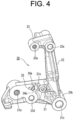
FIG. 4] FIG. 4 is a perspective view of a bracket unit of the auto tensioner. - [
FIG. 5] FIG. 5 is an exploded front view of the auto tensioner. - [
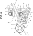
FIG. 6] FIG. 6 is a front diagram illustrating the initial operation of maintenance of a belt. - [
FIG. 7] FIG. 7 is a front diagram illustrating the operation followingFIG. 6 . - The best embodiments of the present invention will now be described with reference to the accompanying drawings.
-
FIGS. 1 to 7 illustrate an embodiment of the present invention. As illustrated inFIG. 1 , a power transmission unit that transmits the rotational power of a crankshaft (not illustrated) to auxiliary equipment (water pump, fan motor, alternator, etc.) on one side surface (for example, the outer surface of afront wall part 1a) of a cylinder block 1 of the engine. - The power transmission unit includes a
crank pulley 2, auxiliary pulleys (a water pump pulley 3, afan pulley 4, analternator pulley 5, etc.),idler pulleys auto tensioner 10 that automatically adjusts the tension of the belt 7. - The engine is a water-cooled engine that cools its cylinder head (not illustrated) and the cylinder block 1 with cooling water.
- Since the tension of the belt 7 may fluctuate due to changes in the angular velocity of the
crank pulley 2 and the load of the auxiliary equipment (not illustrated), the tension of belt 7 is automatically adjusted by theauto tensioner 10. - The
auto tensioner 10 includes atension pulley 11, anarm 12, ahydraulic actuator 13, and is attached to one side surface (an outer surface of thefront wall part 1a) of the cylinder block 1 via abracket 20. - The
tension pulley 11 is pressed against the belt 7 and is rotatably supported via a bearing (not illustrated) at one end (left end) of thearm 12 in the longitudinal direction. - A
central shaft bolt 31 is passed through a central hole of the tension pulley 11 (not illustrated), and thecentral shaft bolt 31 is screwed into a female threadedhole 12a on the left end side of thearm 12. - The
arm 12 is composed of a plate material and is supported by thebracket 20 so that thearm 12 can swing around a fulcrum at a longitudinal midsection. - A
cylindrical fulcrum boss 12b is disposed at the longitudinal midsection of thearm 12. - A
support shaft bolt 32 serving as the support shaft is passed through acentral hole 12c of thefulcrum boss 12b via a collar (not illustrated), and thesupport shaft bolt 32 is screwed into a female threadedhole 21a in thebracket 20. - In
FIG. 1 , when the tension of the belt 7 decreases or when the belt 7 is stretched, thearm 12 rotates clockwise by a predetermined angle around thesupport shaft bolt 32 serving as the fulcrum, and when the tension of the belt 7 increases, thearm 12 rotates counterclockwise by a predetermined angle around thesupport shaft bolt 32 serving as the fulcrum. - The rotation of the
arm 12 by a predetermined angle in one direction and the opposite direction around thesupport shaft bolt 32 serving as the fulcrum is referred to as "swinging." - Although not illustrated in detail, the
hydraulic actuator 13 is, for example, a known direct-acting cylinder. - The
hydraulic actuator 13 automatically adjusts the tension of the belt 7 by extending and retracting to swing thearm 12 in response to the external force acting on thetension pulley 11 due to the tension fluctuation or stretching over time of the belt 7. - One end of the
hydraulic actuator 13 in the direction of extension and retraction (the lower end of ahousing 13a) is supported by the other end (the right end) of thearm 12 in the longitudinal direction via a first bolt (hex bolt) 33. Thefirst bolt 33 is screwed into a female threadedhole 12d disposed on the right end side of thearm 12. - The other end of the
hydraulic actuator 13 in the direction of expansion and contraction (the upper end of apiston 13b) is supported by anattachment piece 23 of abar section 22 of thebracket 20 via asecond bolt 34. Thesecond bolt 34 is screwed into a female threadedhole 23a disposed on theattachment piece 23 of thebracket 20. - As illustrated in
FIG. 1 , Thehydraulic actuator 13 is disposed on thefront wall part 1a of the cylinder block 1 on the outside of the installation area of awater pump 8 via thebracket 20. Note that thewater pump 8 is connected to awater channel 1b in the cylinder block 1. - The
bracket 20 has aplanar section 21 and abar section 22, and is fixed to the cylinder block 1, for example, with third, fourth, andfifth bolts FIG. 1 ). - Specifically, the female threaded
hole 21a into which thesupport shaft bolt 32 of thearm 12 is screwed is disposed at the distal end (the portion connected to the bar section 22) of theplanar section 21, and acylindrical attachment boss 21b is disposed at the proximal end of theplanar section 21. - The
attachment piece 23 is disposed at the upper end of thebar section 22. The female threadedhole 23a is disposed at the distal end of theattachment piece 23. - The third, fourth, and
fifth bolts central hole 21c of theattachment boss 21b, a through-hole 21d disposed near theattachment boss 21b of theplanar section 21, and a through-hole 22a disposed at the upper end of thebar section 22, and the third, fourth, andfifth bolts front wall part 1a of the cylinder block 1. - An
idler pulley 6B is rotatably supported at a predetermined position of thebracket 20. Theidler pulley 6B is rotatably supported by thethird bolt 35 passing through thecentral hole 21c of theattachment boss 21b of thebracket 20. - A
stopper 21e d for restricting the extension of thehydraulic actuator 13 beyond a predetermined limit is disposed on theplanar section 21 of thebracket 20. - The
stopper 21e of the present embodiment, as illustrated inFIGS. 4 and5 , is a thick convex surface disposed at the connecting portion of thebar section 22 and theplanar section 21 of thebracket 20. - The
stopper 21e receives aninclined surface 12g at the right end of thearm 12 to restrict the swinging (rotating) angle of thearm 12 in one direction (clockwise direction), for example, in order to restrict the extension of thehydraulic actuator 13 beyond a predetermined limit. - A first and
second scales arm 12 and anindicator 12e that points to first andsecond scales bracket 20 and thearm 12, respectively. - In the present embodiment, the first and
second scales bracket 20, and theindicator 12e is disposed on thearm 12. - The first and
second scales planar section 21 of thebracket 20, that is on the front surface corresponding to the right end of thearm 12. - The
first scale 24a indicates a normal time during which the belt 7 is not stretched, and thesecond scale 24b indicates when to replace the belt 7 that has stretched beyond a specified limit. - The
indicator 12e is, for example, a V-shaped projection, and is disposed on theinclined surface 12g on the right end of thearm 12 near the end corner. - Since the first and
second scales bracket 20 are immobile, and thearm 12 on which theindicator 12e is disposed rotates by a predetermined angle in a predetermined direction in accordance with the stretching of the belt 7, the tip of theindicator 12e of thearm 12 gradually rotates from thefirst scale 24a toward thesecond scale 24b as the belt 7 stretches over time. - This makes it relatively easy to know when to replace the belt 7 by, for example, being able to visually check the stretching of the belt 7.
- During maintenance of the belt 7, etc., the maintainability of the belt 7 can be improved by using a
work tool 40 for forcing the movement of thetension pulley 11 and thearm 12 in against the urging force of thehydraulic actuator 13 in a direction that reduces the tension of the belt 7, and asupport fixture 50 for restricting the swinging angle of thearm 12 moved by thework tool 40. - Specifically, the
work tool 40 is, for example, a ring wrench or ratchet wrench, and thesupport fixture 50 is, for example, a screwdriver or bar section. - A
catch 12f for locking thework tool 40 is disposed near thefulcrum boss 12b in the middle region in the longitudinal direction of thearm 12. - The
catch 12f has a hexagonal convex outer surface. However, thecatch 12f can be, for example, a convex portion having a hex lobe (hexagonal star) hole on the end surface, in which case thework tool 40 should be a hex lobe wrench (such as a Torx wrench (trademarked)). - A
work hole 25 into which a shaft portion of a screwdriver or bar section, etc. serving as thesupport fixture 50 is disposed near the first andsecond scales planar section 21 of the bracket 20 (near the fixed portion at the lower end of the hydraulic actuator 13). Thework hole 25 is a circular hole. - Specifically, if the belt 7 has been stretched beyond a predetermined length and should be replaced when performing maintenance on the belt 7, the
work hole 25 hidden by thearm 12 inFIG. 6 is exposed as inFIG. 7 by moving thetension pulley 11 so as to loosen the belt 7 by rotating thearm 12 in one direction (see the white arrow inFIG. 6 ) by a predetermined angle with thework tool 40 while thework tool 40 is in a state engaged to thecatch 12f. - The
support fixture 50 is inserted into thework hole 25, and theinclined surface 12g (corresponding to a contacting portion) of thearm 12, which has been moved as described above, comes into contact with thesupport fixture 50 so as to support thearm 12 in an immobilized manner, as illustrated inFIG. 7 . This can improve the maintainability of the belt 7. - As described above, in the embodiment in which the present invention is applied, since the
hydraulic actuator 13 is supported on the outer side of thefront wall part 1a of the cylinder block 1 via thebracket 20, the radiant heat from the cylinder block 1 is blocked by thebracket 20 so that the transmission of the radiant heat to thehydraulic actuator 13 is suppressed. - Since the
hydraulic actuator 13 is disposed on the outer side of thefront wall part 1a of the cylinder block 1 near thewater pump 8, it is difficult for the heat from the hotter parts of the cylinder block 1 to be transferred to thehydraulic actuator 13. - Since these factors suppress in a change in the damping characteristics of the
hydraulic actuator 13, the reliability of theauto tensioner 10 is improved. - Note that the present invention is not limited to the above embodiments, but may be modified as appropriate within the scope of the claims and within the scope of equivalents thereof.
- (1) In the above embodiment, the
bracket 20 has the first andsecond scales work hole 25. However, the present invention is not limited thereto.
For example, although not illustrated, anauto tensioner 10 using abracket 20 not including at least one of the first andsecond scales work hole 25 is also included in the present invention. - (2) In the above embodiment, the
arm 12 has acatch 12f and aninclined surface 12g. However, the present invention is not limited thereto.
For example, although not illustrated, anauto tensioner 10 using anarm 12 without at least one of thecatch 12f and theinclined surface 12g is also included in the present invention. - (3) In the above embodiment, the first and
second scales
For example, although not illustrated, the first andsecond scales - The present invention can be suitably used, for example, in the attachment structure of an auto tensioner that automatically adjusts the tension of a belt that transmits rotational power of the crankshaft of a water-cooled engine to an auxiliary machine.
Claims (5)
- An attachment structure of an auto tensioner that automatically adjusts tension of a belt wrapped around a crank pulley and an auxiliary pulley disposed on one side surface of a cylinder block of an engine, wherein,the auto tensioner is attached to the one side surface of the cylinder block via a bracket,the auto tensioner comprises:a tension pulley that is pressed against the belt;an arm that rotatably supports the tension pulley and is swingably supported by the bracket; anda hydraulic actuator that is supported by the arm and the bracket to adjust a pressing force of the tension pulley against the belt while using a predetermined position of the arm as a fulcrum, andthe hydraulic actuator is disposed on an outer side of a water pump on the one side surface of the cylinder block.
- The attachment structure of the auto tensioner according to claim 1, whereinthe hydraulic actuator is a direct-acting cylinder,the tension pulley is supported at one end of the arm in a longitudinal direction,one end of the hydraulic actuator in a direction of extension and retraction is supported at the other end of the arm in the longitudinal direction,a middle portion of the arm in the longitudinal direction is swingably supported by the bracket via a support shaft, andthe other end of the hydraulic actuator in the direction of extension and retraction is supported by a predetermined portion of the bracket.
- The attachment structure of the auto tensioner according to claim 1 or 2, wherein the bracket has a stopper to restrict extension of the hydraulic actuator beyond a predetermined limit.
- The attachment structure of the auto tensioner according to any one of claims 1 to 3, wherein a scale indicating a swinging angle of the arm and an indicator pointing to the scale are disposed on the bracket and the arm, respectively.
- The attachment structure of the auto tensioner according to any one of claims 1 to 4, wherein,the bracket has a work hole through which a support fixture to restrict the swinging angle of the arm passes, andthe arm has a contacting portion that comes into contact with the support fixture.
Applications Claiming Priority (2)
| Application Number | Priority Date | Filing Date | Title |
|---|---|---|---|
| JP2020051488A JP7491710B2 (en) | 2020-03-23 | 2020-03-23 | Auto tensioner mounting structure |
| PCT/JP2021/005835 WO2021192741A1 (en) | 2020-03-23 | 2021-02-17 | Attachment structure of auto tensioner |
Publications (2)
| Publication Number | Publication Date |
|---|---|
| EP4130449A1 true EP4130449A1 (en) | 2023-02-08 |
| EP4130449A4 EP4130449A4 (en) | 2024-03-06 |
Family
ID=77848030
Family Applications (1)
| Application Number | Title | Priority Date | Filing Date |
|---|---|---|---|
| EP21774205.5A Pending EP4130449A4 (en) | 2020-03-23 | 2021-02-17 | MOUNTING STRUCTURE FOR AN AUTOMATIC TENSIONER |
Country Status (6)
| Country | Link |
|---|---|
| US (1) | US12320423B2 (en) |
| EP (1) | EP4130449A4 (en) |
| JP (1) | JP7491710B2 (en) |
| KR (1) | KR20220155976A (en) |
| CN (1) | CN115244288A (en) |
| WO (1) | WO2021192741A1 (en) |
Families Citing this family (2)
| Publication number | Priority date | Publication date | Assignee | Title |
|---|---|---|---|---|
| JP7168643B2 (en) * | 2020-12-25 | 2022-11-09 | 株式会社クボタ | industrial hybrid engine |
| JP7747714B2 (en) * | 2023-11-24 | 2025-10-01 | 株式会社竹内製作所 | Maintenance Tools |
Family Cites Families (20)
| Publication number | Priority date | Publication date | Assignee | Title |
|---|---|---|---|---|
| JPS587731B2 (en) | 1974-01-17 | 1983-02-12 | オオタ ケイイチ | Dairotsutochiyougosouchi |
| US4277240A (en) * | 1979-08-06 | 1981-07-07 | Dyneer Corporation | Hydraulic belt tensioner construction |
| US5591094A (en) * | 1995-11-01 | 1997-01-07 | The Gates Corporation | Tensioner with adjustable stop for power transmission belt |
| ES2249603T3 (en) * | 2001-07-31 | 2006-04-01 | Litens Automotive Partnership | BELT TENSORS WITH INSTALLATION PIN. |
| JP3750801B2 (en) * | 2002-03-11 | 2006-03-01 | 本田技研工業株式会社 | Hydraulic auto tensioner |
| JP2005214121A (en) * | 2004-01-30 | 2005-08-11 | Bando Chem Ind Ltd | Control device for automatic tensioner |
| JP2005221036A (en) | 2004-02-06 | 2005-08-18 | Mitsubishi Fuso Truck & Bus Corp | Belt tension regulating device of engine |
| JP2007239818A (en) * | 2006-03-07 | 2007-09-20 | Ntn Corp | Tension adjusting device of auxiliary machine driving belt |
| JP2007239902A (en) * | 2006-03-09 | 2007-09-20 | Ntn Corp | Belt tension adjusting device |
| DE102006031518A1 (en) | 2006-07-07 | 2008-01-10 | Schaeffler Kg | Tightening device for a belt drive on an internal combustion engine has a lever arm to rotate in bearings on a base plate by means of an arrangement of bearings with a shock-absorbing mechanism |
| US8057334B2 (en) * | 2009-09-23 | 2011-11-15 | GM Global Technology Operations LLC | Accessory drive tensioner assembly |
| JP2013189945A (en) * | 2012-03-15 | 2013-09-26 | Mitsubishi Motors Corp | Mounting structure of auto tensioner |
| JP2013241962A (en) * | 2012-05-18 | 2013-12-05 | Mitsubishi Electric Engineering Co Ltd | Belt tension adjusting mechanism |
| JP2015010639A (en) * | 2013-06-27 | 2015-01-19 | ダイハツ工業株式会社 | Auto tensioner of internal combustion engine |
| JP6272063B2 (en) | 2014-02-05 | 2018-01-31 | 株式会社Soken | Transmission system |
| JP5807731B1 (en) | 2015-03-20 | 2015-11-10 | スズキ株式会社 | Engine belt tension adjuster |
| FR3039874B1 (en) * | 2015-08-03 | 2017-08-25 | Peugeot Citroen Automobiles Sa | ASSEMBLY COMPRISING AN ENGINE ACCESSORY, A BELT TENSIONER, A FIXING BRACKET AND COMMON CLAMPING MEANS BETWEEN THEM |
| JP2017141903A (en) * | 2016-02-10 | 2017-08-17 | 日野自動車株式会社 | Auto tensioner |
| JP6795427B2 (en) * | 2017-02-28 | 2020-12-02 | ダイハツ工業株式会社 | Internal combustion engine |
| JP6777608B2 (en) * | 2017-09-07 | 2020-10-28 | Ntn株式会社 | Tensioner unit for auxiliary belt |
-
2020
- 2020-03-23 JP JP2020051488A patent/JP7491710B2/en active Active
-
2021
- 2021-02-17 EP EP21774205.5A patent/EP4130449A4/en active Pending
- 2021-02-17 KR KR1020227004613A patent/KR20220155976A/en active Pending
- 2021-02-17 US US17/913,732 patent/US12320423B2/en active Active
- 2021-02-17 CN CN202180005870.6A patent/CN115244288A/en active Pending
- 2021-02-17 WO PCT/JP2021/005835 patent/WO2021192741A1/en not_active Ceased
Also Published As
| Publication number | Publication date |
|---|---|
| JP7491710B2 (en) | 2024-05-28 |
| KR20220155976A (en) | 2022-11-24 |
| JP2021148110A (en) | 2021-09-27 |
| CN115244288A (en) | 2022-10-25 |
| EP4130449A4 (en) | 2024-03-06 |
| US12320423B2 (en) | 2025-06-03 |
| US20230111557A1 (en) | 2023-04-13 |
| WO2021192741A1 (en) | 2021-09-30 |
Similar Documents
| Publication | Publication Date | Title |
|---|---|---|
| EP4130449A1 (en) | Attachment structure of auto tensioner | |
| US6565468B2 (en) | Tensioner with damping mechanism | |
| CN101107462B (en) | Timing belt tensioner | |
| RU2304241C2 (en) | Stretching apparatus of mechanical belt transmission, mechanical drive, and method for stretching of drive belt | |
| JP5285780B2 (en) | Tensioner | |
| KR20170110652A (en) | Double arm tensioner | |
| US8025599B2 (en) | Pivot arm tensioner with sliding ratchet mechanism | |
| US10295043B2 (en) | Method for determining belt wear in a belt drive | |
| US6811506B2 (en) | Engine accessory belt drive with self-aligning pulley | |
| US10066708B2 (en) | External spring to increase tension on belt tensioner for internal combustion engine | |
| US3829176A (en) | Stretcher-pulleys | |
| WO2015176169A1 (en) | Synchronous endless drive member tensioner with tooth skip protection | |
| JP6457222B2 (en) | Friction type auto tensioner | |
| US7220196B2 (en) | Chain drive for an internal combustion engine | |
| CN112303198B (en) | Tensioning of belt drives | |
| EP3701168B1 (en) | Tensioner | |
| RU131436U1 (en) | BELT DRIVE TENSIONER | |
| JP4714609B2 (en) | Variable compression ratio mechanism of internal combustion engine | |
| KR200198629Y1 (en) | Link device for detecting information of engine | |
| JP6593079B2 (en) | Tension adjuster | |
| WO2016067928A1 (en) | Tensioner unit for accessory drive belt | |
| CN108798887A (en) | With the adjustable support for the adjustment front end accessary driving device that stretching, extension mating band is used together | |
| JPH0255663B2 (en) | ||
| JPH04210146A (en) | Belt tension adjustment device | |
| JPH03181645A (en) | Automatic tensioner |
Legal Events
| Date | Code | Title | Description |
|---|---|---|---|
| STAA | Information on the status of an ep patent application or granted ep patent |
Free format text: STATUS: THE INTERNATIONAL PUBLICATION HAS BEEN MADE |
|
| PUAI | Public reference made under article 153(3) epc to a published international application that has entered the european phase |
Free format text: ORIGINAL CODE: 0009012 |
|
| STAA | Information on the status of an ep patent application or granted ep patent |
Free format text: STATUS: REQUEST FOR EXAMINATION WAS MADE |
|
| 17P | Request for examination filed |
Effective date: 20221006 |
|
| AK | Designated contracting states |
Kind code of ref document: A1 Designated state(s): AL AT BE BG CH CY CZ DE DK EE ES FI FR GB GR HR HU IE IS IT LI LT LU LV MC MK MT NL NO PL PT RO RS SE SI SK SM TR |
|
| DAV | Request for validation of the european patent (deleted) | ||
| DAX | Request for extension of the european patent (deleted) | ||
| A4 | Supplementary search report drawn up and despatched |
Effective date: 20240206 |
|
| RIC1 | Information provided on ipc code assigned before grant |
Ipc: F16H 7/12 20060101ALI20240131BHEP Ipc: F02B 67/06 20060101AFI20240131BHEP |
|
| STAA | Information on the status of an ep patent application or granted ep patent |
Free format text: STATUS: EXAMINATION IS IN PROGRESS |
|
| 17Q | First examination report despatched |
Effective date: 20240912 |