EP4130439A1 - Secondary flow suppression structure - Google Patents
Secondary flow suppression structure Download PDFInfo
- Publication number
- EP4130439A1 EP4130439A1 EP21780091.1A EP21780091A EP4130439A1 EP 4130439 A1 EP4130439 A1 EP 4130439A1 EP 21780091 A EP21780091 A EP 21780091A EP 4130439 A1 EP4130439 A1 EP 4130439A1
- Authority
- EP
- European Patent Office
- Prior art keywords
- cavity
- seal surface
- outer shroud
- secondary flow
- stator vane
- Prior art date
- Legal status (The legal status is an assumption and is not a legal conclusion. Google has not performed a legal analysis and makes no representation as to the accuracy of the status listed.)
- Pending
Links
Images



Classifications
-
- F—MECHANICAL ENGINEERING; LIGHTING; HEATING; WEAPONS; BLASTING
- F01—MACHINES OR ENGINES IN GENERAL; ENGINE PLANTS IN GENERAL; STEAM ENGINES
- F01D—NON-POSITIVE DISPLACEMENT MACHINES OR ENGINES, e.g. STEAM TURBINES
- F01D5/00—Blades; Blade-carrying members; Heating, heat-insulating, cooling or antivibration means on the blades or the members
- F01D5/12—Blades
- F01D5/14—Form or construction
- F01D5/141—Shape, i.e. outer, aerodynamic form
- F01D5/145—Means for influencing boundary layers or secondary circulations
-
- F—MECHANICAL ENGINEERING; LIGHTING; HEATING; WEAPONS; BLASTING
- F01—MACHINES OR ENGINES IN GENERAL; ENGINE PLANTS IN GENERAL; STEAM ENGINES
- F01D—NON-POSITIVE DISPLACEMENT MACHINES OR ENGINES, e.g. STEAM TURBINES
- F01D11/00—Preventing or minimising internal leakage of working-fluid, e.g. between stages
- F01D11/08—Preventing or minimising internal leakage of working-fluid, e.g. between stages for sealing space between rotor blade tips and stator
-
- F—MECHANICAL ENGINEERING; LIGHTING; HEATING; WEAPONS; BLASTING
- F01—MACHINES OR ENGINES IN GENERAL; ENGINE PLANTS IN GENERAL; STEAM ENGINES
- F01D—NON-POSITIVE DISPLACEMENT MACHINES OR ENGINES, e.g. STEAM TURBINES
- F01D5/00—Blades; Blade-carrying members; Heating, heat-insulating, cooling or antivibration means on the blades or the members
- F01D5/12—Blades
- F01D5/14—Form or construction
- F01D5/141—Shape, i.e. outer, aerodynamic form
- F01D5/142—Shape, i.e. outer, aerodynamic form of the blades of successive rotor or stator blade-rows
- F01D5/143—Contour of the outer or inner working fluid flow path wall, i.e. shroud or hub contour
-
- F—MECHANICAL ENGINEERING; LIGHTING; HEATING; WEAPONS; BLASTING
- F01—MACHINES OR ENGINES IN GENERAL; ENGINE PLANTS IN GENERAL; STEAM ENGINES
- F01D—NON-POSITIVE DISPLACEMENT MACHINES OR ENGINES, e.g. STEAM TURBINES
- F01D5/00—Blades; Blade-carrying members; Heating, heat-insulating, cooling or antivibration means on the blades or the members
- F01D5/12—Blades
- F01D5/22—Blade-to-blade connections, e.g. for damping vibrations
- F01D5/225—Blade-to-blade connections, e.g. for damping vibrations by shrouding
-
- F—MECHANICAL ENGINEERING; LIGHTING; HEATING; WEAPONS; BLASTING
- F01—MACHINES OR ENGINES IN GENERAL; ENGINE PLANTS IN GENERAL; STEAM ENGINES
- F01D—NON-POSITIVE DISPLACEMENT MACHINES OR ENGINES, e.g. STEAM TURBINES
- F01D9/00—Stators
- F01D9/02—Nozzles; Nozzle boxes; Stator blades; Guide conduits, e.g. individual nozzles
-
- F—MECHANICAL ENGINEERING; LIGHTING; HEATING; WEAPONS; BLASTING
- F05—INDEXING SCHEMES RELATING TO ENGINES OR PUMPS IN VARIOUS SUBCLASSES OF CLASSES F01-F04
- F05D—INDEXING SCHEME FOR ASPECTS RELATING TO NON-POSITIVE-DISPLACEMENT MACHINES OR ENGINES, GAS-TURBINES OR JET-PROPULSION PLANTS
- F05D2220/00—Application
- F05D2220/30—Application in turbines
-
- F—MECHANICAL ENGINEERING; LIGHTING; HEATING; WEAPONS; BLASTING
- F05—INDEXING SCHEMES RELATING TO ENGINES OR PUMPS IN VARIOUS SUBCLASSES OF CLASSES F01-F04
- F05D—INDEXING SCHEME FOR ASPECTS RELATING TO NON-POSITIVE-DISPLACEMENT MACHINES OR ENGINES, GAS-TURBINES OR JET-PROPULSION PLANTS
- F05D2240/00—Components
- F05D2240/10—Stators
- F05D2240/12—Fluid guiding means, e.g. vanes
-
- F—MECHANICAL ENGINEERING; LIGHTING; HEATING; WEAPONS; BLASTING
- F05—INDEXING SCHEMES RELATING TO ENGINES OR PUMPS IN VARIOUS SUBCLASSES OF CLASSES F01-F04
- F05D—INDEXING SCHEME FOR ASPECTS RELATING TO NON-POSITIVE-DISPLACEMENT MACHINES OR ENGINES, GAS-TURBINES OR JET-PROPULSION PLANTS
- F05D2240/00—Components
- F05D2240/55—Seals
Definitions
- the present disclosure relates to a secondary flow suppression structure in an axial turbine.
- a gas turbine engine such as a jet engine is installed with an axial turbine to rotationally drive a compressor.
- the axial turbine has a plurality of rotor blades and a plurality of stator vanes. These are arranged alternately in an axial direction and constitute at least one stage.
- the rotor blades are arranged in a circumferential direction at predetermined intervals to constitute a blade cascade.
- the stator vanes are arranged in the circumferential direction at predetermined intervals to constitute a vane cascade.
- a tip of the rotor blade is provided with an outer shroud.
- a tip of the stator vane is provided with an outer band.
- a hub of the rotor blade is provided with an inner shroud, and a hub of the stator vane is provided with an inner band.
- the outer shroud and the outer band are outer walls constituting a flow passage (main passage) of the working fluid passing through the blade cascade and the vane cascade.
- the inner shroud and the inner band are inner walls constituting the flow passage of the working fluid.
- the rotor blade has a dovetail radially inwardly of the inner shroud.
- the dovetail is attached to a rotor connected to a shaft.
- the tip of the stator vane is fixed to the casing via a support member of the stator vane.
- the outer shroud is separated from a seal surface located inside the casing to allow a rotation of the rotor.
- a fin is provided on the outer surface of the outer shroud to suppress passing of the working fluid through this space.
- Patent Literature 1 JP 2015-108340 A
- the fin is provided between the outer shroud of the rotor blade and the seal surface. Although the tips of the fins are as close as possible to the seal surface, they are not in contact with each other. Accordingly, as a leakage, the working fluid partially flows from the main passage into the space between the outer shroud of the rotor blade and the seal surface. The leakage passes between the outer shroud and seal surface and then returns to the main path from between the outer shroud of the rotor blade and the outer band of the stator vane.
- the aforementioned leakage induces separation of the working fluid on the pressure side of the stator vane due to the impact of the leakage to a leading edge of the stator vane and the suction side in the vicinity thereof. This separation is relatively large and increases the secondary flow near the tip of the stator vane. This increase in secondary flow results in a decrease in turbine efficiency.
- the present disclosure is made in view of the above circumstances. That is, it is an object of the present disclosure to provide a secondary flow suppression structure capable of suppressing an increase in secondary flow caused by a leakage in an axial turbine.
- a secondary flow suppression structure includes: a turbine rotor blade including an outer shroud; a turbine stator vane located rearward of the turbine rotor blade and including an outer band; a seal surface facing the outer shroud at a radially outside of the outer shroud; and a cavity formed between the seal surface and the turbine stator vane, formed in an annular shape extending in a circumferential direction, and provided with an opening portion opening radially inward on a virtual surface of the seal surface extending rearward; wherein the outer shroud includes a fin protruding toward the seal surface.
- a front end of the outer band may be positioned at the same height as the virtual surface in a radial direction, or positioned radially inward of the virtual surface.
- the opening portion of the cavity may be located rearward of a position where the fin and the seal surface face each other.
- a gap may be formed between a support member of the seal surface and a support member of the outer band, and the gap may be connected with the cavity and may have a width shorter than that of the cavity at a position where the gap is connected with the cavity.
- a secondary flow suppression structure 10 is applied to an axial turbine of a gas turbine engine for an aircraft or an electric generator.
- an extending direction of a rotational center axis of rotor blades 12 in the axial turbine is defined as the axial direction AD.
- a circumferential direction CD and a radial direction RD are defined around this rotational center axis.
- a term "forward (front)” and a term “rearward (rear)" represent an upstream side and a downstream side of the flow of the working fluid WF, respectively.
- FIG. 1 is a conceptual diagram illustrating the secondary flow suppression structure 10.
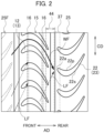
- FIG. 2 is a development view of a blade cascade (blade row) 15 and vane cascades (vane row) 25 and 25F along the circumferential direction CD.
- the secondary flow suppression structure 10 according to the present embodiment includes rotor blades (turbine rotor blades) 12, stator vanes (turbine stator vanes) 22, a seal surface 32, and a cavity 42.
- FIG. 1 illustrates a single wall surface W which represents the seal surface 32 and an outer band 24 of the stator vane 22 in order to simply show the structure of the secondary flow suppression structure 10. Therefore, in the example shown in this figure, the cavity 42 is formed on the wall surface W.
- the rotor blade 12 includes an airfoil part 13 and an outer shroud 14 provided on a tip 13t of the airfoil part 13 (i.e., of the rotor blade 12).
- the outer shroud 14 is an outer wall defining a flow passage 52 of the working fluid WF.
- the outer shroud 14 is integrated with the airfoil part 13. As shown in FIG. 2 , the rotor blades 12 are arranged in the circumferential direction CD to constitute the blade cascade 15.
- the stator vanes 22 are located rearward of the blade cascade 15.
- the stator vane 22 includes an airfoil part 23 and an outer band 24 provided on a tip 23t of the airfoil part 23 (i.e., of the stator vane 22).
- the outer band 24 is an outer wall defining the flow passage 52 of the working fluid WF together with the outer shroud 14.
- the outer band 24 is integrated with the airfoil part 23.
- the stator vanes 22 are arranged in the circumferential direction CD to constitute the vane cascade 25.
- a position (height) of the front end 24a of the outer band 24 along the radial direction RD can be arbitrarily set with respect to a virtual surface 34. That is, in the radial direction RD, the front end 24a may be positioned radially outward of the virtual surface 34, may be positioned at the same height, or may be positioned radially inward of the virtual surface 34. However, by positioning the front end 24a at the same position or radially inward of the virtual surface 34, it is possible to mitigate an impingement of a leakage (leak flow) LF as described later on the suction side 22s of the stator vane 22, compared with the case where the front end 24a is radially outward of the virtual surface 34.
- the seal surface 32 is located radially outward of the outer shroud 14.
- the seal surface 32 faces the outer surface 14a of the outer shroud 14 and is formed in an annular shape extending in the circumferential direction CD to surround the blade cascade 15 from the radial outside.
- the seal surface 32 is, for example, a honeycomb seal having a known structure or a layered body having a predetermined thickness including an abrasive material.
- the outer shroud 14 includes at least one fin 16.
- the fin 16 is integrally formed with the outer surface 14a of the outer shroud 14 and projects from the outer surface 14a toward the seal surface 32.
- the fin 16 extends in the circumferential direction CD from one end side to the other side of the outer shroud 14 in the circumferential direction CD.
- the fin 16 has a predetermined width in the axial direction AD. This width is sufficiently narrower than the width of the outer shroud 14.
- the fin 16 forms an annular wall on the outer surface 14a of the outer shroud 14 together with other fins of the other blades adjacent in the circumferential direction CD (see FIG. 2 ).
- the number of fins 16 may be one or more. However, when multiple fins 16 are provided with the outer shroud 14, the most downstream fin of them constitutes the secondary flow suppression structure 10.
- the tip 16a of the fin 16 faces the seal surface 32 with a predetermined clearance.
- This clearance is sufficiently smaller than the distance between the outer surface 14a of the outer shroud 14 and the seal surface 32. Accordingly, the fin 16 and the seal surface 32 form a narrow portion 36.
- the narrow portion 36 narrows a space in the radial direction RD, which is defined by the outer surface 14a of the outer shroud 14 and the seal surface 32. That is, the fin 16 suppresses the flow of the leakage LF together with the seal surface 32, or control the amount of the leakage LF, while defining the clearance that allows the rotation of the rotor blades 12.
- the cavity 42 is formed between the seal surface 32 and the stator vane 22 in the axial direction AD.
- the cavity 42 is an annular groove or recess which opens radially inward and extends in the circumferential direction CD.
- the cavity 42 is formed in a member such as a honeycomb seal that includes the seal surface 32.
- the cavity 42 is also located within a region 48 between the rear end 32a of the seal surface 32 and the front end 24a of the outer shroud 14.
- the cavity 42 is formed of an inner peripheral surface 43 and an opening portion 44.
- the inner peripheral surface 43 forms an internal space of the cavity 42.
- the opening portion 44 opens on the virtual surface 34 which extends rearward from the seal surface 32.
- the opening portion 44 opens radially inward from the internal space of the cavity 42.
- the inner peripheral surface 43 includes, annular side surfaces 43a and 43a and a bottom surface 43b, for example, the annular side surfaces 43a and 43a are parallel and opposed to each other and extend in the circumferential direction CD.
- the bottom surface 43b is located radially outward of the side surfaces 43a and 43a.
- the cavity 42 has a rectangular cross-section.
- the cavity 42 may be formed entirely or partially between the rear end 32a of the seal surface 32 and the front end 24a of the outer shroud 14.
- the opening portion 44 of the cavity 42 is located behind the narrow portion 36.
- the opening portion 44 is located rearward from the most rearward one of the narrow portions 36.
- the opening portion 44 is closer to the front end 24a of the outer band 24 than the position(s) where the tip(s) 16a of the fin(s) 16 and the seal surface 32 face each other. That is, the cavity 42 is formed at a position (region 48) that does not interfere with the constriction of the flow caused by the narrow portion 36.
- the width and depth of the cavity 42 are set to values that change the original flow (i.e., the flow when the cavity 42 is not present) of the leakage LF due to the presence of the cavity 42.
- the caused flow change is, for example, a swirl, a turn (deflection), a deceleration (stagnation) in and near the cavity 42. These values can be obtained by numerical analysis such as CFD (Computational Fluid Dynamics), etc.
- the width of the cavity 42 is the maximum length of the cavity 42 along the axial direction AD, and is substantially the length of the opening portion 44 along the axial direction AD.
- the depth of the cavity 42 is the length from the opening portion 44 (virtual surface 34) of the cavity 42 along the radial direction RD to the bottom surface 43b of the inner peripheral surface 43.
- the cross-sectional shape of the cavity 42 orthogonal to the circumferential direction CD is, for example, a rectangle shown in FIG. 1 .
- the cross-sectional shape of the cavity 42 is not limited to the rectangular shape as long as the cavity 42 can change the original flow of the leakage LF.
- FIG. 3 is a side view illustrating changes in the secondary flow SF caused by the cavity 42.
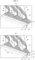
- FIG. 4 is a perspective view illustrating distributions of the secondary flow SF in the vicinity of the tip 23t of the stator vane 22, FIG. 4(a) illustrates the distribution when the cavity 42 is not present, and FIG. 4(b) illustrates the distribution when the cavity 42 is present.
- Gray indicates a space in which the secondary flow SF flows, and arrows in this space indicate the flow directions of the secondary flow SF.
- the outer shroud 14 of the rotor blade 12 includes the fin 16 that projects toward the seal surface 32.
- the tip 16a of the fin 16 is as close as possible to the seal surface 32 with the clearance described above, but is not in contact with the seal surface 32. Accordingly, the leakage LF passes between the outer shroud 14 of the rotor blade 12 and the seal surface 32, and then flows (i.e., returns) into the flow passage 52 of the working fluid WF from between the outer shroud 14 of the rotor blade 12 and the outer band 24 of the stator vane 22.
- the working fluid WF is already deflected by the vane cascade 25F located forward of the blade cascade 15 before flowing into the blade cascade 15.
- the leakage LF is a flow entering the space between the outer shroud 14 and the seal surface 32. Therefore, the leakage LF is subjected to the same deflection as the working fluid WF.
- the working fluid WF passes through the blade cascade 15, the working fluid WF is deflected by the blade cascade 15 in a direction opposite to a direction in which the vane cascade 25F deflects the working fluid WF, and flows into the vane cascade 25 located rearward of the blade cascade 15.
- the leakage LF is not deflected by the blade cascade 15 and flows into the flow passage 52 while maintaining its flow direction. Therefore, the leakage LF impinges on the suction side 22s at and near the leading edge 22a of the stator vane 22 of the vane cascade 25 at a large angle with respect to the flow direction of the working fluid WF.
- This impingement of the leakage LF induces or enhances separation of the working fluid WF near the tip 23t on the pressure side 22p of the stator vane 22. Since the separation of the working fluid WF on the pressure side 22p is relatively large, the secondary flow SF in the vicinity of the tip 23t is increased, thereby resulting in a decrease in turbine efficiency. In particular, the secondary flow SF in the vicinity of the tip 23t is more likely to increase in the pressure side 22p (see FIG. 2 ) of the stator vane 22 than in the suction side 22s (see FIG. 2 ) of the stator vane 22.
- the cavity 42 formed in front of the vane cascade 25 changes the original flow of the leakage LF in or near the cavity 42.
- cavity 42 If cavity 42 is not formed, it can only flow along the seal surface 32 (or virtual surface 34). That is, the leakage LF maintains the original flow. On the other hand, when the cavity 42 is formed as shown in FIG. 3 , the leakage LF flowing out of the narrow portion 36 enters the cavity 42 to form swirls as shown in FIG. 3 , for example. In this case, it can be considered that the cavity 42 deflects the leakage LF toward the vane cascade 25 or moderates its speed.
- a potential i.e., a pressure field
- the leakage LF flows away from the leading edge 22a of the stator vane 22 and preferentially flows in a space between the stator vane 22 and the stator vane 22 in which the potential is lower than that at the leading edge 22a.
- the secondary flow SF when the cavity 42 is not present is inhibited from flowing radially inward and is more likely to flow along the outer band 24. This means that the increase of the secondary flow is suppressed.
- FIG. 5 illustrates a portion of the turbine 60.
- unillustrated configurations of the turbine 60 such as the turbine shaft and others can apply known configurations.
- the rotor blade 12 includes an inner shroud 17 and a dovetail 18 in addition to the airfoil part 13 and the outer shroud 14 described above.
- the inner shroud 17 is provided at the hub 13h of the airfoil part 13, and the dovetail 18 is provided radially inward of the inner shroud 17.
- the inner shroud 17 and the dovetail 18 are integrated with the airfoil part 13.
- the dovetail 18 is fitted to the rotor 19, and the rotor 19 is coupled to a shaft (not shown) connected to a rotor blade of a compressor (not shown).
- the stator vane 22 includes an inner band 26 and a seal member 27 in addition to the airfoil part 23 and the outer band 24 described above.
- the inner band 26 is provided at the hub 23h of the airfoil part 23, and the seal member 27 is provided radially inwardly of the inner band 26.
- the inner band 26 is an inner wall defining the flow passage 52 of the working fluid WF together with the inner shroud 17.
- the seal surface 32 is supported with a support member 35. As shown in FIG. 5 , the support member 35 is a structure interposed between the seal surface 32 and a casing 38 of the turbine 60.
- the outer band 24 of the stator vane (i.e., the stator vane 22) is fixed to the casing 38 via a support member 28 such as a ring or a flange provided radially outward thereof.
- the support member 28 may be integrated with the outer band 24.
- a gap 45 may be formed between the support member 35 of the seal surface 32 and the support member 28 of the outer band 24 (see FIG. 1 ).
- the gap 45 is connected with the cavity 42 and opens, for example, on the bottom surface 43b of the inner peripheral surface 43.
- the gap 45 has a width (a length along the axial direction AD) shorter than that of the cavity 42 at a position where the gap 45 is connected with the cavity 42.
- the gap 45 is intended to prevent physical interference between the support member 35 and the support member 28, and the width of the gap 45 has a value that does not interfere with the flow of the leakage LF. Thus, even if the gap 45 is formed, the effect of the cavity 42 is not lost.
Landscapes
- Engineering & Computer Science (AREA)
- Mechanical Engineering (AREA)
- General Engineering & Computer Science (AREA)
- Physics & Mathematics (AREA)
- Fluid Mechanics (AREA)
- Turbine Rotor Nozzle Sealing (AREA)
Abstract
Description
- The present disclosure relates to a secondary flow suppression structure in an axial turbine.
- A gas turbine engine such as a jet engine is installed with an axial turbine to rotationally drive a compressor. The axial turbine has a plurality of rotor blades and a plurality of stator vanes. These are arranged alternately in an axial direction and constitute at least one stage. The rotor blades are arranged in a circumferential direction at predetermined intervals to constitute a blade cascade. Similarly, the stator vanes are arranged in the circumferential direction at predetermined intervals to constitute a vane cascade.
- A tip of the rotor blade is provided with an outer shroud. A tip of the stator vane is provided with an outer band. Similarly, a hub of the rotor blade is provided with an inner shroud, and a hub of the stator vane is provided with an inner band. The outer shroud and the outer band are outer walls constituting a flow passage (main passage) of the working fluid passing through the blade cascade and the vane cascade. The inner shroud and the inner band are inner walls constituting the flow passage of the working fluid.
- The rotor blade has a dovetail radially inwardly of the inner shroud. The dovetail is attached to a rotor connected to a shaft. On the other hand, the tip of the stator vane is fixed to the casing via a support member of the stator vane.
- The outer shroud is separated from a seal surface located inside the casing to allow a rotation of the rotor. In this regard, a fin is provided on the outer surface of the outer shroud to suppress passing of the working fluid through this space.
- Patent Literature 1:
JP 2015-108340 A - As described above, the fin is provided between the outer shroud of the rotor blade and the seal surface. Although the tips of the fins are as close as possible to the seal surface, they are not in contact with each other. Accordingly, as a leakage, the working fluid partially flows from the main passage into the space between the outer shroud of the rotor blade and the seal surface. The leakage passes between the outer shroud and seal surface and then returns to the main path from between the outer shroud of the rotor blade and the outer band of the stator vane.
- The aforementioned leakage induces separation of the working fluid on the pressure side of the stator vane due to the impact of the leakage to a leading edge of the stator vane and the suction side in the vicinity thereof. This separation is relatively large and increases the secondary flow near the tip of the stator vane. This increase in secondary flow results in a decrease in turbine efficiency.
- The present disclosure is made in view of the above circumstances. That is, it is an object of the present disclosure to provide a secondary flow suppression structure capable of suppressing an increase in secondary flow caused by a leakage in an axial turbine.
- A secondary flow suppression structure according to the present disclosure includes: a turbine rotor blade including an outer shroud; a turbine stator vane located rearward of the turbine rotor blade and including an outer band; a seal surface facing the outer shroud at a radially outside of the outer shroud; and a cavity formed between the seal surface and the turbine stator vane, formed in an annular shape extending in a circumferential direction, and provided with an opening portion opening radially inward on a virtual surface of the seal surface extending rearward; wherein the outer shroud includes a fin protruding toward the seal surface.
- A front end of the outer band may be positioned at the same height as the virtual surface in a radial direction, or positioned radially inward of the virtual surface. The opening portion of the cavity may be located rearward of a position where the fin and the seal surface face each other. A gap may be formed between a support member of the seal surface and a support member of the outer band, and the gap may be connected with the cavity and may have a width shorter than that of the cavity at a position where the gap is connected with the cavity.
- According to the present disclosure, it is possible to provide a secondary flow suppression structure capable of suppressing an increase in secondary flow caused by a leakage in an axial turbine.
-
-
FIG. 1 is a conceptual diagram illustrating a secondary flow suppression structure according to an embodiment of the present disclosure. -
FIG. 2 is a development view illustrating a blade cascade and vane cascades along the circumferential direction. -
FIG. 3 is a side view illustrating changes in secondary flow caused by a cavity. -
FIG. 4 is a perspective view illustrating distributions of the secondary flow in the vicinity of the tip of the stator vane, whereinFIG. 4(a) illustrates the distribution when a cavity is not present, andFIG. 4(b) illustrates the distribution when the cavity is present. -
FIG. 5 is a view illustrating a part of an example of an axial turbine to which the secondary flow suppression structure is applied. - Some exemplary embodiments are described below with reference to the drawings. It should be noted that the same reference numerals are given to the common parts in the respective figures, and the redundant description thereof will be omitted. A secondary
flow suppression structure 10 according to the present embodiment is applied to an axial turbine of a gas turbine engine for an aircraft or an electric generator. For convenience of explanation, an extending direction of a rotational center axis ofrotor blades 12 in the axial turbine is defined as the axial direction AD. A circumferential direction CD and a radial direction RD are defined around this rotational center axis. A term "forward (front)" and a term "rearward (rear)" represent an upstream side and a downstream side of the flow of the working fluid WF, respectively. - A configuration of the secondary
flow suppression structure 10 will be described.FIG. 1 is a conceptual diagram illustrating the secondaryflow suppression structure 10.FIG. 2 is a development view of a blade cascade (blade row) 15 and vane cascades (vane row) 25 and 25F along the circumferential direction CD. The secondaryflow suppression structure 10 according to the present embodiment includes rotor blades (turbine rotor blades) 12, stator vanes (turbine stator vanes) 22, aseal surface 32, and acavity 42.FIG. 1 illustrates a single wall surface W which represents theseal surface 32 and anouter band 24 of thestator vane 22 in order to simply show the structure of the secondaryflow suppression structure 10. Therefore, in the example shown in this figure, thecavity 42 is formed on the wall surface W. - The
rotor blade 12 includes anairfoil part 13 and anouter shroud 14 provided on atip 13t of the airfoil part 13 (i.e., of the rotor blade 12). Theouter shroud 14 is an outer wall defining aflow passage 52 of the working fluid WF. Theouter shroud 14 is integrated with theairfoil part 13. As shown inFIG. 2 , therotor blades 12 are arranged in the circumferential direction CD to constitute theblade cascade 15. - The
stator vanes 22 are located rearward of theblade cascade 15. Thestator vane 22 includes anairfoil part 23 and anouter band 24 provided on atip 23t of the airfoil part 23 (i.e., of the stator vane 22). Theouter band 24 is an outer wall defining theflow passage 52 of the working fluid WF together with theouter shroud 14. Theouter band 24 is integrated with theairfoil part 23. As shown inFIG. 2 , thestator vanes 22 are arranged in the circumferential direction CD to constitute thevane cascade 25. - A position (height) of the
front end 24a of theouter band 24 along the radial direction RD can be arbitrarily set with respect to avirtual surface 34. That is, in the radial direction RD, thefront end 24a may be positioned radially outward of thevirtual surface 34, may be positioned at the same height, or may be positioned radially inward of thevirtual surface 34. However, by positioning thefront end 24a at the same position or radially inward of thevirtual surface 34, it is possible to mitigate an impingement of a leakage (leak flow) LF as described later on thesuction side 22s of thestator vane 22, compared with the case where thefront end 24a is radially outward of thevirtual surface 34. - The
seal surface 32 is located radially outward of theouter shroud 14. Theseal surface 32 faces theouter surface 14a of theouter shroud 14 and is formed in an annular shape extending in the circumferential direction CD to surround theblade cascade 15 from the radial outside. Theseal surface 32 is, for example, a honeycomb seal having a known structure or a layered body having a predetermined thickness including an abrasive material. - The
outer shroud 14 includes at least onefin 16. Thefin 16 is integrally formed with theouter surface 14a of theouter shroud 14 and projects from theouter surface 14a toward theseal surface 32. Thefin 16 extends in the circumferential direction CD from one end side to the other side of theouter shroud 14 in the circumferential direction CD. Thefin 16 has a predetermined width in the axial direction AD. This width is sufficiently narrower than the width of theouter shroud 14. Thus, thefin 16 forms an annular wall on theouter surface 14a of theouter shroud 14 together with other fins of the other blades adjacent in the circumferential direction CD (seeFIG. 2 ). As described above, the number offins 16 may be one or more. However, whenmultiple fins 16 are provided with theouter shroud 14, the most downstream fin of them constitutes the secondaryflow suppression structure 10. - The
tip 16a of thefin 16 faces theseal surface 32 with a predetermined clearance. This clearance is sufficiently smaller than the distance between theouter surface 14a of theouter shroud 14 and theseal surface 32. Accordingly, thefin 16 and theseal surface 32 form anarrow portion 36. Thenarrow portion 36 narrows a space in the radial direction RD, which is defined by theouter surface 14a of theouter shroud 14 and theseal surface 32. That is, thefin 16 suppresses the flow of the leakage LF together with theseal surface 32, or control the amount of the leakage LF, while defining the clearance that allows the rotation of therotor blades 12. - The
cavity 42 is formed between theseal surface 32 and thestator vane 22 in the axial direction AD. Thecavity 42 is an annular groove or recess which opens radially inward and extends in the circumferential direction CD. For example, thecavity 42 is formed in a member such as a honeycomb seal that includes theseal surface 32. Thecavity 42 is also located within aregion 48 between therear end 32a of theseal surface 32 and thefront end 24a of theouter shroud 14. Thecavity 42 is formed of an innerperipheral surface 43 and anopening portion 44. The innerperipheral surface 43 forms an internal space of thecavity 42. The openingportion 44 opens on thevirtual surface 34 which extends rearward from theseal surface 32. The openingportion 44 opens radially inward from the internal space of thecavity 42. The innerperipheral surface 43 includes, annular side surfaces 43a and 43a and abottom surface 43b, for example, the annular side surfaces 43a and 43a are parallel and opposed to each other and extend in the circumferential direction CD. Thebottom surface 43b is located radially outward of the side surfaces 43a and 43a. In this case, thecavity 42 has a rectangular cross-section. Thecavity 42 may be formed entirely or partially between therear end 32a of theseal surface 32 and thefront end 24a of theouter shroud 14. - As shown in
FIG. 1 , the openingportion 44 of thecavity 42 is located behind thenarrow portion 36. When multiplenarrow portions 36 are formed withmultiple fins 16, the openingportion 44 is located rearward from the most rearward one of thenarrow portions 36. In other words, the openingportion 44 is closer to thefront end 24a of theouter band 24 than the position(s) where the tip(s) 16a of the fin(s) 16 and theseal surface 32 face each other. That is, thecavity 42 is formed at a position (region 48) that does not interfere with the constriction of the flow caused by thenarrow portion 36. - The width and depth of the
cavity 42 are set to values that change the original flow (i.e., the flow when thecavity 42 is not present) of the leakage LF due to the presence of thecavity 42. The caused flow change is, for example, a swirl, a turn (deflection), a deceleration (stagnation) in and near thecavity 42. These values can be obtained by numerical analysis such as CFD (Computational Fluid Dynamics), etc. The width of thecavity 42 is the maximum length of thecavity 42 along the axial direction AD, and is substantially the length of the openingportion 44 along the axial direction AD. The depth of thecavity 42 is the length from the opening portion 44 (virtual surface 34) of thecavity 42 along the radial direction RD to thebottom surface 43b of the innerperipheral surface 43. - The cross-sectional shape of the
cavity 42 orthogonal to the circumferential direction CD is, for example, a rectangle shown inFIG. 1 . However, the cross-sectional shape of thecavity 42 is not limited to the rectangular shape as long as thecavity 42 can change the original flow of the leakage LF. - Each flow of the working fluid WF, the leakage LF, and the secondary flow SF will be described.
FIG. 3 is a side view illustrating changes in the secondary flow SF caused by thecavity 42.FIG. 4 is a perspective view illustrating distributions of the secondary flow SF in the vicinity of thetip 23t of thestator vane 22,FIG. 4(a) illustrates the distribution when thecavity 42 is not present, andFIG. 4(b) illustrates the distribution when thecavity 42 is present. Gray indicates a space in which the secondary flow SF flows, and arrows in this space indicate the flow directions of the secondary flow SF. These distributions are based on results of the CFD analysis. - As described above, the
outer shroud 14 of therotor blade 12 includes thefin 16 that projects toward theseal surface 32. Thetip 16a of thefin 16 is as close as possible to theseal surface 32 with the clearance described above, but is not in contact with theseal surface 32. Accordingly, the leakage LF passes between theouter shroud 14 of therotor blade 12 and theseal surface 32, and then flows (i.e., returns) into theflow passage 52 of the working fluid WF from between theouter shroud 14 of therotor blade 12 and theouter band 24 of thestator vane 22. - As shown in
FIG. 2 , the working fluid WF is already deflected by thevane cascade 25F located forward of theblade cascade 15 before flowing into theblade cascade 15. Of the working fluid WF having passed through thevane cascade 25F, the leakage LF is a flow entering the space between theouter shroud 14 and theseal surface 32. Therefore, the leakage LF is subjected to the same deflection as the working fluid WF. - When the working fluid WF passes through the
blade cascade 15, the working fluid WF is deflected by theblade cascade 15 in a direction opposite to a direction in which thevane cascade 25F deflects the working fluid WF, and flows into thevane cascade 25 located rearward of theblade cascade 15. On the other hand, the leakage LF is not deflected by theblade cascade 15 and flows into theflow passage 52 while maintaining its flow direction. Therefore, the leakage LF impinges on thesuction side 22s at and near theleading edge 22a of thestator vane 22 of thevane cascade 25 at a large angle with respect to the flow direction of the working fluid WF. - This impingement of the leakage LF induces or enhances separation of the working fluid WF near the
tip 23t on thepressure side 22p of thestator vane 22. Since the separation of the working fluid WF on thepressure side 22p is relatively large, the secondary flow SF in the vicinity of thetip 23t is increased, thereby resulting in a decrease in turbine efficiency. In particular, the secondary flow SF in the vicinity of thetip 23t is more likely to increase in thepressure side 22p (seeFIG. 2 ) of thestator vane 22 than in thesuction side 22s (seeFIG. 2 ) of thestator vane 22. - As described above, the separation of the working fluid WF on the
pressure side 22p results from the impingement of the leakage LF on thesuction side 22s near theleading edge 22a. Therefore, in the present embodiment, thecavity 42 formed in front of thevane cascade 25 changes the original flow of the leakage LF in or near thecavity 42. - If
cavity 42 is not formed, it can only flow along the seal surface 32 (or virtual surface 34). That is, the leakage LF maintains the original flow. On the other hand, when thecavity 42 is formed as shown inFIG. 3 , the leakage LF flowing out of thenarrow portion 36 enters thecavity 42 to form swirls as shown inFIG. 3 , for example. In this case, it can be considered that thecavity 42 deflects the leakage LF toward thevane cascade 25 or moderates its speed. - In the region (space) 37 (see
FIG. 2 ) on the front side of thevane cascade 25 in which theleading edge 22a of thestator vane 22 is included, a potential (i.e., a pressure field) along the circumferential direction CD becomes highest at theleading edge 22a of thestator vane 22 and decreases as it moves away from theleading edge 22a. Accordingly, the leakage LF flows away from theleading edge 22a of thestator vane 22 and preferentially flows in a space between thestator vane 22 and thestator vane 22 in which the potential is lower than that at theleading edge 22a. - Accordingly, the impingement of the leakage LF on the
leading edge 22a and thesuction side 22s of thestator vane 22 when thecavity 42 is present (seeFIG. 4(b) ) is mitigated compared with that when thecavity 42 is not present (seeFIG. 4(a) ). That is, the separation of the working fluid WF on thepressure side 22p, which is caused by the impingement on thesuction side 22s at and near theleading edge 22a, is suppressed, and the increase of the secondary flow SF near theleading edge 22a due to the leakage LF is suppressed. Consequently, the decrease of the turbine efficiency is also suppressed. - Further, compared with the secondary flow SF when the
cavity 42 is not present (indicated by dotted lines inFIG. 3 ), the secondary flow SF when thecavity 42 is present (indicated by solid lines inFIG. 3 ) is inhibited from flowing radially inward and is more likely to flow along theouter band 24. This means that the increase of the secondary flow is suppressed. - An example of a
turbine 60, to which the secondaryflow suppression structure 10 described above is applied, will be described.FIG. 5 illustrates a portion of theturbine 60. Here, unillustrated configurations of theturbine 60 such as the turbine shaft and others can apply known configurations. - As shown in
FIG. 5 , therotor blade 12 includes aninner shroud 17 and adovetail 18 in addition to theairfoil part 13 and theouter shroud 14 described above. Theinner shroud 17 is provided at thehub 13h of theairfoil part 13, and thedovetail 18 is provided radially inward of theinner shroud 17. Theinner shroud 17 and thedovetail 18 are integrated with theairfoil part 13. Thedovetail 18 is fitted to therotor 19, and therotor 19 is coupled to a shaft (not shown) connected to a rotor blade of a compressor (not shown). - The
stator vane 22 includes aninner band 26 and aseal member 27 in addition to theairfoil part 23 and theouter band 24 described above. Theinner band 26 is provided at thehub 23h of theairfoil part 23, and theseal member 27 is provided radially inwardly of theinner band 26. Theinner band 26 is an inner wall defining theflow passage 52 of the working fluid WF together with theinner shroud 17. - The
seal surface 32 is supported with asupport member 35. As shown inFIG. 5 , thesupport member 35 is a structure interposed between theseal surface 32 and acasing 38 of theturbine 60. - The
outer band 24 of the stator vane (i.e., the stator vane 22) is fixed to thecasing 38 via asupport member 28 such as a ring or a flange provided radially outward thereof. Thesupport member 28 may be integrated with theouter band 24. - A
gap 45 may be formed between thesupport member 35 of theseal surface 32 and thesupport member 28 of the outer band 24 (seeFIG. 1 ). In this case, thegap 45 is connected with thecavity 42 and opens, for example, on thebottom surface 43b of the innerperipheral surface 43. Thegap 45 has a width (a length along the axial direction AD) shorter than that of thecavity 42 at a position where thegap 45 is connected with thecavity 42. Thegap 45 is intended to prevent physical interference between thesupport member 35 and thesupport member 28, and the width of thegap 45 has a value that does not interfere with the flow of the leakage LF. Thus, even if thegap 45 is formed, the effect of thecavity 42 is not lost. - It should be noted that the present disclosure is not limited to the embodiments described above, is shown by the description of the claims, and further includes all modifications within the meaning and scope of the same as the description of the claims.
Claims (4)
- A secondary flow suppression structure comprising:a turbine rotor blade including an outer shroud;a turbine stator vane located rearward of the turbine rotor blade and including an outer band;a seal surface facing the outer shroud at a radially outside of the outer shroud; anda cavity formed between the seal surface and the turbine stator vane, formed in an annular shape extending in a circumferential direction, and provided with an opening portion opening radially inward on a virtual surface of the seal surface extending rearward; whereinthe outer shroud includes a fin protruding toward the seal surface.
- The secondary flow suppression structure according to claim 1, wherein
a front end of the outer band is positioned at the same height as the virtual surface in a radial direction, or positioned radially inward of the virtual surface. - The secondary flow suppression structure according to claim 1 or 2, wherein
the opening portion of the cavity is located rearward of a position where the fin and the seal surface face each other. - The secondary flow suppression structure according to claim 1 or 2, wherein:a gap is formed between a support member of the seal surface and a support member of the outer band, andthe gap is connected with the cavity and has a width shorter than that of the cavity at a position where the gap is connected with the cavity.
Applications Claiming Priority (2)
| Application Number | Priority Date | Filing Date | Title |
|---|---|---|---|
| JP2020060319 | 2020-03-30 | ||
| PCT/JP2021/005338 WO2021199718A1 (en) | 2020-03-30 | 2021-02-12 | Secondary flow suppression structure |
Publications (2)
| Publication Number | Publication Date |
|---|---|
| EP4130439A1 true EP4130439A1 (en) | 2023-02-08 |
| EP4130439A4 EP4130439A4 (en) | 2024-05-01 |
Family
ID=77928275
Family Applications (1)
| Application Number | Title | Priority Date | Filing Date |
|---|---|---|---|
| EP21780091.1A Pending EP4130439A4 (en) | 2020-03-30 | 2021-02-12 | Secondary flow suppression structure |
Country Status (4)
| Country | Link |
|---|---|
| US (1) | US11808156B2 (en) |
| EP (1) | EP4130439A4 (en) |
| JP (1) | JP7380846B2 (en) |
| WO (1) | WO2021199718A1 (en) |
Families Citing this family (2)
| Publication number | Priority date | Publication date | Assignee | Title |
|---|---|---|---|---|
| JP7306481B2 (en) * | 2019-12-05 | 2023-07-11 | 日本電信電話株式会社 | Distributed processing system |
| CA3182646A1 (en) * | 2021-12-24 | 2023-06-24 | Itp Next Generation Turbines, S.L. | A turbine arrangement including a turbine outlet stator vane arrangement |
Family Cites Families (35)
| Publication number | Priority date | Publication date | Assignee | Title |
|---|---|---|---|---|
| JPS578302A (en) * | 1980-06-19 | 1982-01-16 | Hitachi Ltd | Internal stage structure of multistage axial-flow machine |
| JPS58165201U (en) * | 1982-04-30 | 1983-11-02 | 三菱重工業株式会社 | Turbine blade seal structure |
| US5632598A (en) * | 1995-01-17 | 1997-05-27 | Dresser-Rand | Shrouded axial flow turbo machine utilizing multiple labrinth seals |
| RU2151884C1 (en) | 1998-04-07 | 2000-06-27 | Открытое акционерное общество "Авиадвигатель" | Turbine of gas turbine engine |
| JP2002371802A (en) * | 2001-06-14 | 2002-12-26 | Mitsubishi Heavy Ind Ltd | Shroud integrated type moving blade in gas turbine and split ring |
| GB0218060D0 (en) | 2002-08-03 | 2002-09-11 | Alstom Switzerland Ltd | Sealing arrangements |
| JP2009047043A (en) * | 2007-08-17 | 2009-03-05 | Mitsubishi Heavy Ind Ltd | Axial flow turbine |
| JP4848440B2 (en) * | 2009-03-03 | 2011-12-28 | 株式会社日立製作所 | Axial flow turbine |
| JP2011001894A (en) * | 2009-06-19 | 2011-01-06 | Toshiba Corp | Low-pressure steam turbine |
| US20110070072A1 (en) * | 2009-09-23 | 2011-03-24 | General Electric Company | Rotary machine tip clearance control mechanism |
| KR101411177B1 (en) * | 2009-12-07 | 2014-06-23 | 미츠비시 쥬고교 가부시키가이샤 | Turbine and turbine rotor blade |
| US9194239B2 (en) * | 2010-01-20 | 2015-11-24 | Mitsubishi Heavy Industries, Ltd. | Turbine rotor blade and turbo machine |
| JP5558138B2 (en) * | 2010-02-25 | 2014-07-23 | 三菱重工業株式会社 | Turbine |
| JP5484990B2 (en) | 2010-03-30 | 2014-05-07 | 三菱重工業株式会社 | Turbine |
| US8936247B2 (en) * | 2010-05-18 | 2015-01-20 | General Electric Company | Seal assembly including plateau and concave portion in mating surface for seal tooth in turbine |
| JP5591042B2 (en) | 2010-09-17 | 2014-09-17 | 三菱重工業株式会社 | Turbine |
| JP2012211527A (en) * | 2011-03-30 | 2012-11-01 | Mitsubishi Heavy Ind Ltd | Gas turbine |
| JP2013194519A (en) | 2012-03-15 | 2013-09-30 | Mitsubishi Heavy Ind Ltd | Turbine |
| EP2647796A1 (en) * | 2012-04-04 | 2013-10-09 | MTU Aero Engines GmbH | Seal system for a turbo engine |
| ES2700788T3 (en) * | 2012-04-04 | 2019-02-19 | MTU Aero Engines AG | Sealing system for a turbomachine |
| JP6233578B2 (en) | 2013-12-05 | 2017-11-22 | 株式会社Ihi | Turbine |
| JP6374760B2 (en) * | 2014-10-24 | 2018-08-15 | 三菱重工業株式会社 | Axial turbine and turbocharger |
| JP6518526B2 (en) * | 2015-06-18 | 2019-05-22 | 三菱日立パワーシステムズ株式会社 | Axial flow turbine |
| US20170030213A1 (en) * | 2015-07-31 | 2017-02-02 | Pratt & Whitney Canada Corp. | Turbine section with tip flow vanes |
| JP2017061898A (en) | 2015-09-25 | 2017-03-30 | 株式会社東芝 | Steam turbine |
| JP6597117B2 (en) | 2015-09-25 | 2019-10-30 | いすゞ自動車株式会社 | Output device and output device control method |
| US10458263B2 (en) * | 2015-10-12 | 2019-10-29 | Rolls-Royce North American Technologies Inc. | Turbine shroud with sealing features |
| JP2018040282A (en) * | 2016-09-07 | 2018-03-15 | 三菱日立パワーシステムズ株式会社 | Axial flow turbine and diaphragm outer ring thereof |
| DE102016222720A1 (en) * | 2016-11-18 | 2018-05-24 | MTU Aero Engines AG | Sealing system for an axial flow machine and axial flow machine |
| JP6417381B2 (en) | 2016-11-21 | 2018-11-07 | 本田技研工業株式会社 | Oil separation device for internal combustion engine |
| EP3358142B1 (en) * | 2017-02-02 | 2021-08-18 | General Electric Company | Turbine tip shroud leakage flow control |
| DE112018002978T5 (en) * | 2017-06-12 | 2020-02-20 | Mitsubishi Hitachi Power Systems, Ltd. | Axialströmungsdrehmaschine |
| JP7061497B2 (en) * | 2018-03-30 | 2022-04-28 | 三菱重工航空エンジン株式会社 | Aircraft gas turbine |
| JP7148273B2 (en) * | 2018-05-21 | 2022-10-05 | 三菱重工業株式会社 | steam turbine |
| CN112513426B (en) * | 2018-08-08 | 2023-05-23 | 三菱重工业株式会社 | Rotary machine and seal member |
-
2021
- 2021-02-12 WO PCT/JP2021/005338 patent/WO2021199718A1/en not_active Ceased
- 2021-02-12 EP EP21780091.1A patent/EP4130439A4/en active Pending
- 2021-02-12 JP JP2022511623A patent/JP7380846B2/en active Active
-
2022
- 2022-05-09 US US17/662,537 patent/US11808156B2/en active Active
Also Published As
| Publication number | Publication date |
|---|---|
| WO2021199718A1 (en) | 2021-10-07 |
| JPWO2021199718A1 (en) | 2021-10-07 |
| EP4130439A4 (en) | 2024-05-01 |
| US20220259983A1 (en) | 2022-08-18 |
| JP7380846B2 (en) | 2023-11-15 |
| US11808156B2 (en) | 2023-11-07 |
Similar Documents
| Publication | Publication Date | Title |
|---|---|---|
| EP2136033B1 (en) | Wall of turbo machine and turbo machine | |
| EP2096262A1 (en) | Axial flow turbine with low shroud leakage losses | |
| US8784045B2 (en) | Seal assembly | |
| EP3159504B1 (en) | Radial-inflow type axial turbine and turbocharger | |
| US20160333714A1 (en) | Sealing structure and rotary machine | |
| KR101939520B1 (en) | turbine | |
| US20160177833A1 (en) | Engine and method for operating said engine | |
| EP2083175B1 (en) | Stator blade and rotor blade of compressor | |
| US11136897B2 (en) | Seal device and turbomachine | |
| US11808156B2 (en) | Secondary flow suppression structure | |
| EP3177811B1 (en) | Gas turbine engine compressor | |
| US20160298477A1 (en) | Shroud arrangement of a row of blades of stator vanes or rotor blades | |
| KR20200104788A (en) | Axial flow turbine | |
| EP3064709B1 (en) | Turbine bucket platform for influencing hot gas incursion losses | |
| US11047246B2 (en) | Blade or vane, blade or vane segment and assembly for a turbomachine, and turbomachine | |
| US20210131293A1 (en) | Rotor blade, rotor unit, and rotating machine | |
| KR102318119B1 (en) | Axial flow turbine | |
| CN112513424A (en) | Turbine blade | |
| US11898461B2 (en) | Axial flow turbine | |
| JP7190370B2 (en) | axial turbine | |
| US12270302B2 (en) | Turbine | |
| US9951631B2 (en) | Turbomachine rotor blade | |
| JP5591986B2 (en) | End wall member and gas turbine | |
| WO2017072844A1 (en) | Rotary machine |
Legal Events
| Date | Code | Title | Description |
|---|---|---|---|
| STAA | Information on the status of an ep patent application or granted ep patent |
Free format text: STATUS: THE INTERNATIONAL PUBLICATION HAS BEEN MADE |
|
| PUAI | Public reference made under article 153(3) epc to a published international application that has entered the european phase |
Free format text: ORIGINAL CODE: 0009012 |
|
| STAA | Information on the status of an ep patent application or granted ep patent |
Free format text: STATUS: REQUEST FOR EXAMINATION WAS MADE |
|
| 17P | Request for examination filed |
Effective date: 20221031 |
|
| AK | Designated contracting states |
Kind code of ref document: A1 Designated state(s): AL AT BE BG CH CY CZ DE DK EE ES FI FR GB GR HR HU IE IS IT LI LT LU LV MC MK MT NL NO PL PT RO RS SE SI SK SM TR |
|
| DAV | Request for validation of the european patent (deleted) | ||
| DAX | Request for extension of the european patent (deleted) | ||
| A4 | Supplementary search report drawn up and despatched |
Effective date: 20240404 |
|
| RIC1 | Information provided on ipc code assigned before grant |
Ipc: F01D 5/22 20060101ALI20240327BHEP Ipc: F01D 5/14 20060101ALI20240327BHEP Ipc: F01D 9/02 20060101ALI20240327BHEP Ipc: F01D 5/20 20060101ALI20240327BHEP Ipc: F01D 11/08 20060101AFI20240327BHEP |
|
| STAA | Information on the status of an ep patent application or granted ep patent |
Free format text: STATUS: EXAMINATION IS IN PROGRESS |
|
| 17Q | First examination report despatched |
Effective date: 20260119 |