EP4130433B1 - Hybride versorgungskonfiguration für axialströmungsprallbleche - Google Patents
Hybride versorgungskonfiguration für axialströmungsprallbleche Download PDFInfo
- Publication number
- EP4130433B1 EP4130433B1 EP22189285.4A EP22189285A EP4130433B1 EP 4130433 B1 EP4130433 B1 EP 4130433B1 EP 22189285 A EP22189285 A EP 22189285A EP 4130433 B1 EP4130433 B1 EP 4130433B1
- Authority
- EP
- European Patent Office
- Prior art keywords
- airfoil
- cooling
- airfoil body
- hole
- baffle
- Prior art date
- Legal status (The legal status is an assumption and is not a legal conclusion. Google has not performed a legal analysis and makes no representation as to the accuracy of the status listed.)
- Active
Links
Images


Classifications
-
- F—MECHANICAL ENGINEERING; LIGHTING; HEATING; WEAPONS; BLASTING
- F01—MACHINES OR ENGINES IN GENERAL; ENGINE PLANTS IN GENERAL; STEAM ENGINES
- F01D—NON-POSITIVE DISPLACEMENT MACHINES OR ENGINES, e.g. STEAM TURBINES
- F01D5/00—Blades; Blade-carrying members; Heating, heat-insulating, cooling or antivibration means on the blades or the members
- F01D5/12—Blades
- F01D5/14—Form or construction
- F01D5/18—Hollow blades, i.e. blades with cooling or heating channels or cavities; Heating, heat-insulating or cooling means on blades
- F01D5/187—Convection cooling
- F01D5/188—Convection cooling with an insert in the blade cavity to guide the cooling fluid, e.g. forming a separation wall
-
- F—MECHANICAL ENGINEERING; LIGHTING; HEATING; WEAPONS; BLASTING
- F05—INDEXING SCHEMES RELATING TO ENGINES OR PUMPS IN VARIOUS SUBCLASSES OF CLASSES F01-F04
- F05D—INDEXING SCHEME FOR ASPECTS RELATING TO NON-POSITIVE-DISPLACEMENT MACHINES OR ENGINES, GAS-TURBINES OR JET-PROPULSION PLANTS
- F05D2220/00—Application
- F05D2220/30—Application in turbines
- F05D2220/32—Application in turbines in gas turbines
-
- F—MECHANICAL ENGINEERING; LIGHTING; HEATING; WEAPONS; BLASTING
- F05—INDEXING SCHEMES RELATING TO ENGINES OR PUMPS IN VARIOUS SUBCLASSES OF CLASSES F01-F04
- F05D—INDEXING SCHEME FOR ASPECTS RELATING TO NON-POSITIVE-DISPLACEMENT MACHINES OR ENGINES, GAS-TURBINES OR JET-PROPULSION PLANTS
- F05D2240/00—Components
- F05D2240/20—Rotors
- F05D2240/30—Characteristics of rotor blades, i.e. of any element transforming dynamic fluid energy to or from rotational energy and being attached to a rotor
- F05D2240/304—Characteristics of rotor blades, i.e. of any element transforming dynamic fluid energy to or from rotational energy and being attached to a rotor related to the trailing edge of a rotor blade
-
- F—MECHANICAL ENGINEERING; LIGHTING; HEATING; WEAPONS; BLASTING
- F05—INDEXING SCHEMES RELATING TO ENGINES OR PUMPS IN VARIOUS SUBCLASSES OF CLASSES F01-F04
- F05D—INDEXING SCHEME FOR ASPECTS RELATING TO NON-POSITIVE-DISPLACEMENT MACHINES OR ENGINES, GAS-TURBINES OR JET-PROPULSION PLANTS
- F05D2250/00—Geometry
- F05D2250/10—Two-dimensional
- F05D2250/18—Two-dimensional patterned
- F05D2250/185—Two-dimensional patterned serpentine-like
-
- F—MECHANICAL ENGINEERING; LIGHTING; HEATING; WEAPONS; BLASTING
- F05—INDEXING SCHEMES RELATING TO ENGINES OR PUMPS IN VARIOUS SUBCLASSES OF CLASSES F01-F04
- F05D—INDEXING SCHEME FOR ASPECTS RELATING TO NON-POSITIVE-DISPLACEMENT MACHINES OR ENGINES, GAS-TURBINES OR JET-PROPULSION PLANTS
- F05D2260/00—Function
- F05D2260/20—Heat transfer, e.g. cooling
- F05D2260/221—Improvement of heat transfer
- F05D2260/2214—Improvement of heat transfer by increasing the heat transfer surface
- F05D2260/22141—Improvement of heat transfer by increasing the heat transfer surface using fins or ribs
-
- Y—GENERAL TAGGING OF NEW TECHNOLOGICAL DEVELOPMENTS; GENERAL TAGGING OF CROSS-SECTIONAL TECHNOLOGIES SPANNING OVER SEVERAL SECTIONS OF THE IPC; TECHNICAL SUBJECTS COVERED BY FORMER USPC CROSS-REFERENCE ART COLLECTIONS [XRACs] AND DIGESTS
- Y02—TECHNOLOGIES OR APPLICATIONS FOR MITIGATION OR ADAPTATION AGAINST CLIMATE CHANGE
- Y02T—CLIMATE CHANGE MITIGATION TECHNOLOGIES RELATED TO TRANSPORTATION
- Y02T50/00—Aeronautics or air transport
- Y02T50/60—Efficient propulsion technologies, e.g. for aircraft
Definitions
- the present disclosure relates to cooling structures for gas turbine engines, and, more specifically, to airfoil cooling structures.
- the present invention relates to an airfoil for use in a gas turbine engine, to a turbine section of a gas turbine engine, and to a gas turbine engine.
- a gas turbine engine typically includes a fan section, a compressor section, a combustor section, and a turbine section.
- a fan section may drive air along a bypass flow path while a compressor section may drive air along a core flow path.
- air is pressurized in the compressor section and is mixed with fuel and burned in the combustor section to generate hot combustion gases.
- the hot combustion gases flow through the turbine section, which extracts energy from the hot combustion gases to power the compressor section and other gas turbine engine loads.
- the compressor section typically includes low pressure and high pressure compressors, and the turbine section includes low pressure and high pressure turbines.
- the turbine section includes multiple stages of blades and vanes. As fluid flows through the turbine section, the flow causes the blades to rotate about an axis of rotation.
- the vanes, positioned between each row of blades, are used to redirect the flow in order to maximize the power received by the downstream blades.
- Temperatures within the turbine section may be relatively high, as the flow of fluid is received initially from the combustor section of the gas turbine engine. Cooling air may be extracted from the compressor section and used to cool the gas path components. Cooled components may include, for example, rotating blades and stator vanes in the turbine section.
- the airfoils in the turbine section often included multiple cavities, which may be arranged at the leading edge, the trailing edge, and/or other locations.
- the size and shape of the trailing edge cavity due to the shape of the airfoil coupled with a lower supply pressure source may require the use of a space-eater baffle for cooling.
- EP 3 354 854 B1 discloses a prior art airfoil as set forth in the preamble of claim 1.
- an airfoil for use in a gas turbine engine as recited in claim 1.
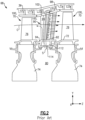
- FIG. 1 schematically illustrates a gas turbine engine 20.
- the gas turbine engine 20 is disclosed herein as a two-spool turbofan that generally incorporates a fan section 22, a compressor section 24, a combustor section 26 and a turbine section 28.
- the fan section 22 drives air along a bypass flow path B in a bypass duct defined within a housing 15 such as a fan case or nacelle, and also drives air along a core flow path C for compression and communication into the combustor section 26 then expansion through the turbine section 28.
- the exemplary engine 20 generally includes a low speed spool 30 and a high speed spool 32 mounted for rotation about an engine central longitudinal axis X relative to an engine static structure 36 via several bearing systems 38. It should be understood that various bearing systems 38 at various locations may alternatively or additionally be provided, and the location of bearing systems 38 may be varied as appropriate to the application.
- the low speed spool 30 generally includes an inner shaft 40 that interconnects, a first (or low) pressure compressor 44 and a first (or low) pressure turbine 46.
- the inner shaft 40 is connected to the fan 42 through a speed change mechanism, which in exemplary gas turbine engine 20 is illustrated as a geared architecture 48 to drive a fan 42 at a lower speed than the low speed spool 30.
- the high speed spool 32 includes an outer shaft 50 that interconnects a second (or high) pressure compressor 52 and a second (or high) pressure turbine 54.
- a combustor 56 is arranged in the exemplary gas turbine 20 between the high pressure compressor 52 and the high pressure turbine 54.
- a mid-turbine frame 57 of the engine static structure 36 may be arranged generally between the high pressure turbine 54 and the low pressure turbine 46.
- the mid-turbine frame 57 further supports bearing systems 38 in the turbine section 28.
- the inner shaft 40 and the outer shaft 50 are concentric and rotate via bearing systems 38 about the engine central longitudinal axis X which is collinear with their longitudinal axes.
- the core airflow is compressed by the low pressure compressor 44 then the high pressure compressor 52, mixed and burned with fuel in the combustor 56, then expanded through the high pressure turbine 54 and low pressure turbine 46.
- the mid-turbine frame 57 includes airfoils 59 which are in the core airflow path C.
- the turbines 46, 54 rotationally drive the respective low speed spool 30 and high speed spool 32 in response to the expansion.
- gear system 48 may be located aft of the low pressure compressor, or aft of the combustor section 26 or even aft of turbine section 28, and fan 42 may be positioned forward or aft of the location of gear system 48.
- the engine 20 in one example is a high-bypass geared aircraft engine.
- the engine 20 bypass ratio is greater than about six (6), with an example embodiment being greater than about ten (10), and can be less than or equal to about 18.0, or more narrowly can be less than or equal to 16.0.
- the geared architecture 48 is an epicyclic gear train, such as a planetary gear system or other gear system, with a gear reduction ratio of greater than about 2.3.
- the gear reduction ratio may be less than or equal to 4.0.
- the low pressure turbine 46 has a pressure ratio that is greater than about five.
- the low pressure turbine pressure ratio can be less than or equal to 13.0, or more narrowly less than or equal to 12.0.
- the engine 20 bypass ratio is greater than about ten (10:1)
- the fan diameter is significantly larger than that of the low pressure compressor 44
- the low pressure turbine 46 has a pressure ratio that is greater than about five 5:1.
- Low pressure turbine 46 pressure ratio is pressure measured prior to an inlet of low pressure turbine 46 as related to the pressure at the outlet of the low pressure turbine 46 prior to an exhaust nozzle.
- the geared architecture 48 may be an epicycle gear train, such as a planetary gear system or other gear system, with a gear reduction ratio of greater than about 2.3:1 and less than about 5:1. It should be understood, however, that the above parameters are only exemplary of one embodiment of a geared architecture engine and that the present invention is applicable to other gas turbine engines including direct drive turbofans.
- the fan section 22 of the engine 20 is designed for a particular flight condition -- typically cruise at about 0.8 Mach and about 35,000 feet (10,668 meters).
- the flight condition of 0.8 Mach and 35,000 ft (10,668 meters), with the engine at its best fuel consumption - also known as "bucket cruise Thrust Specific Fuel Consumption ('TSFC')" - is the industry standard parameter of lbm of fuel being burned divided by lbf of thrust the engine produces at that minimum point.
- 'TSFC' Thrust Specific Fuel Consumption
- “Low fan pressure ratio” is the pressure ratio across the fan blade alone, without a Fan Exit Guide Vane (“FEGV”) system.
- the low fan pressure ratio as disclosed herein according to one non-limiting embodiment is less than about 1.45, or more narrowly greater than or equal to 1.25.
- Low corrected fan tip speed is the actual fan tip speed in ft/sec divided by an industry standard temperature correction of [(Tram °R) / (518.7 °R)] 0.5 .
- the "Low corrected fan tip speed" as disclosed herein according to one non-limiting embodiment is less than about 1150.0 ft / second (350.5 meters/second), and can be greater than or equal to 1000.0 ft / second (304.8 meters/second).
- each of low pressure compressor 44, high pressure compressor 52, low pressure turbine 46, and high pressure turbine 54 in gas turbine engine 20 may comprise one or more stages or sets of rotating blades and one or more stages or sets of stationary vanes axially interspersed with the associated blade stages but non-rotating about engine central longitudinal axis X.
- Each compressor stage and turbine stage may comprise multiple interspersed stages of blades 70 and vanes 90.
- the blades 70 rotate about engine central longitudinal axis X, while the vanes 90 remain stationary with respect to engine central longitudinal axis X.
- Blades 70 and vanes 90 may be referred to as airfoils 100.
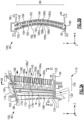
- FIG. 2 schematically shows, by example, a portion of an engine section 68, which is illustrated as a turbine section 28 of gas turbine engine 20.
- Engine section 68 may include a circumferential array of blades 70 coupled about a circumference of a generally circular disk 74.
- Disk 74 may be disposed radially inward of core flowpath C and centered on the rotation axis of the gas turbine engine.
- Disk 74 with blades 70 may be configured to rotate about engine central longitudinal axis X
- Each blade 70 may include an airfoil body 76 with a platform disposed at an inner diameter end wall 72 of the blade 70.
- a disk cavity 80 may be defined between a forward disk and an aft disk. Upstream (forward) and downstream (aft) of blades 70 are circumferential arrays of vanes 90 configured to guide core flowpath C through the engine section 68.
- Each vane 90 may include an airfoil body 96 with an inner diameter platform 94 disposed at an inner diameter end wall 92 of vane 90 and with an outer diameter platform 98 disposed at an outer diameter end wall 102 of vane 90.
- Outer diameter platform 98 may be coupled to engine case structure 36.
- Inner diameter platform 94 and/or outer diameter platform 98 may be coupled to or integral with vane 90.
- vane 90 may comprise an internal cooling system 110 having a first cooling structure 120 and a second cooling structure 150.
- Internal cooling system 110 is configured to convectively remove heat from the airfoil body 96 of vane 90.
- a secondary airflow path S may be defined within disk cavity 80 and may contain a cooling fluid.
- the cooling fluid such as bleed air, may be introduced into a cavity 112 of inner diameter platform 94 through an orifice 114 in inner diameter platform 94.
- the coolant may flow into a vane via a vane outer diameter cavity.
- First cooling structure 120 and second cooling structure 150 may be configured to direct the cooling fluid as a cooling airflow 140 through airfoil body 96.
- Blade 70 may similarly include an internal cooling system, such as internal cooling system 110.
- Airfoil 100 having first cooling structure 120 and second cooling structure 150 may be a blade or a vane. Airfoil 100 is depicted in FIG. 3A as a vane 90, however, the features may be applicable to blades 70 (see FIG. 5 ). Airfoil 100 may be a vane 90 comprising a trailing edge 122 facing an aft direction in the gas turbine engine and leading edge 124 facing a forward direction in the gas turbine engine. Leading edge 124 and trailing edge 122 may be configured and oriented to direct airflow through engine section 68 ( FIG. 2 ). Airfoil body 96 of vane 90 may extend from an inner diameter end wall 92 to outer diameter end wall 102 of vane 90.
- FIG. 3B illustrates a cross-sectional view of an airfoil 100 taken along line 3B-3B of FIG. 3A , in accordance with various embodiments.
- Airfoil body 96 may include a pressure side wall 160 (i.e. having a generally concave surface) and a suction side wall 162 (i.e. having a generally convex surface) joined together at the respective trailing edge 122 and leading edge 124 ( FIG. 3B ).
- An airfoil body 96 may be configured to accommodate first cooling structure 120 and second cooling structure 150.
- an internal cooling system 110 of vane 90 may comprise a first cooling structure 120 configured to remove heat from airfoil body 96.
- First cooling structure 120 comprises one or more ribs 170, which define one or more radial passages 172 within airfoil body 96.
- Radial passages 172 extend in generally the radial direction, i.e., the y-direction on the provided x-y-z axes.
- Ribs 170 may extend in the x-y-plane from a pressure side 160 to suction side wall 162, and from the inner diameter end wall 92 to the outer diameter end wall 102.
- ribs 170 may extend between a pressure side 160 and suction side wall 162, and extend between the inner diameter end wall 92 and the outer diameter end wall 102.
- vane 90 may include any number of radial passages 172 and any number of ribs 170.
- the radial passages 172 are each separated by ribs 170.
- Radial passages 172 are configured to conduct cooling airflow 140 in a radial direction (y-direction) through airfoil body 96.
- Radial passages 172 operate as a conduit for cooling airflow 140 and provide control over the flow and temperature of cooling airflow 140.
- the airfoil 100 is configured to be more uniformly cooled from inner diameter end wall 92 to outer diameter end wall 102 and from leading edge 124 to trailing edge 122.
- first cooling structure 120 may receive cooling airflow 140 from a secondary airflow path S at inner diameter end wall 92 of airfoil body 96. In various embodiments, first cooling structure 120 may receive the cooling airflow from the outer diameter of the vane. Cooling airflow 140 may be conducted from the inner diameter end wall 92 radially outward through radial passages 172. Radial passages 172 may comprise parallel channels and may have a serpentine geometry. In that regard, the radial passages 172 may include one or more turn 174, which may redirect the cooling airflow 140 from flowing in a first radial direction, such as the positive y-direction, to flowing in a second radial direction, such as the negative y-direction.
- turn 174 may comprise a 180-degree turn.
- a portion of cooling airflow 140 may be discharged through a plurality of apertures 168 at leading edge 124.
- Apertures 168 may be cylindrical, circular, oval, teardrop, rectangular, slots, ellipses, irregular, or other shape.
- Apertures 168 may be radially and/or axially oriented.
- Another portion of cooling airflow 140 may be directed through radial passages 172 of first cooling structure 120 and to a second cooling structure 150.
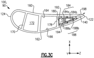
- FIG. 3C illustrates a cross-sectional view of an airfoil 100 taken along line 3C-3C of FIG. 3A , in accordance with various embodiments.
- Ribs 170 may contact an inner surface 164 of pressure side wall 160 and an inner surface 166 of suction side wall 162.
- Ribs 170 may couple pressure side wall 160 and suction side wall 162 and may provide structural support to the pressure side wall 160 and suction side wall 162 to reduce bulging and/or deformation of the walls 160, 162 due gas path pressure loadings, metal temperatures, and thermal gradients.
- a distance between ribs 170 may be decreased, and a quantity of ribs 170 increased (i.e., increasing the density of ribs 170) to provide additional support for walls 160, 162.
- the airfoil walls i.e., pressure side wall 160 and suction side wall 162
- the thinner airfoil walls may be more efficiently cooled by cooling airflow 140 than thicker airfoil walls.
- vane 90 may further comprise a second cooling structure 150 configured to remove heat from airfoil body 96.
- Second cooling structure 150 may comprise one or more baffles 180 which may define one or more radial passages 182 through airfoil body 96.
- Second cooling structure 150 may further comprise one or more axial passages 184 within airfoil body 96 and extend in a chordwise direction of the airfoil.
- second cooling structure 150 may be disposed aft of first cooling structure 120 within the airfoil body 96, and the axial passages 184 may be configured to direct the cooling airflow 140 through an aft portion of the airfoil body 96.
- Axial passages 184 may include pressure side axial passages and suction side axial passages .
- a baffle 180 may extend in the y-z-plane from an aft rib 178 toward trailing edge 122, and from the inner diameter end wall 92 to the outer diameter end wall 102 of airfoil body 96. Baffle 180 may be offset from pressure side wall 160 and suction side wall 162.
- the pressure source supplying cooling fluid to the first and second cooling structures 120, 150 is also responsible for supplying air to the turbine rotor (i.e., rotor onboard injector (ROBI) using a baffle 180 as a through-flow jumper tube.
- ROBI rotor onboard injector
- the cavity sizing, amount of flow pulled through to the ROBI (in area of disk cavity 80), and the amount of additional cooling air required to cool the trailing edge leads to a scenario where Mach numbers inside the baffle reach ⁇ 0.2, for example. This relatively high Mach number leads to a significant radial component as the air enters the axial channels, impacting the development region of the channel.
- Baffle 180 may define an inner passage 186, which may be a radial passage 182, within baffle 180, and may further define a plurality of openings 188. Cooling fluid flows through the baffle 180 in a fluid flow direction F, as indicated by the dashed arrows in FIGS 3A and 3B . Openings 188 formed in baffle 180 may include a plurality of first openings 188 a formed at a pressure side and/or suction side wall. Openings 188 formed in baffle 180 may include a plurality of second openings 188 b formed in a trailing edge 189 of baffle 180.
- the openings 188 are provided as multiple holes including first and second holes 188a, 188a' that are configured to conduct the cooling airflow in an axial/chordwise direction toward the trailing edge 122 of the airfoil body.
- a first standoff 190a extends from the airfoil body to support the baffle 180.
- the first axial standoff 190a has a first length defining an axial passage that includes the multiple holes 188a, 188a'.
- a second standoff 190b has a second length less than the first length, which form parallel first and second passageways 184a, 184b, in one example.
- the standoffs could be in other orientations, if desired, for example, them to squeeze or open channels depending on heat-load requirements throughout the span of the airfoil.
- the second standoff 190b provides an additional heat sink between the airfoil body and the baffle 180.
- the second standoff 190b is arranged radially between the first and second holes 188a, 188a'.
- the first hole 188a is smaller than the second hole 188a', and the second hole 188a' is downstream from the first hole 188a relative to the fluid flow direction F.
- the larger second hole 188a' is able to make up for the pressure drop as compared to the smaller first hole 188a as the cooling fluid flows radially.
- the downstream hole is made larger to encourage more flow through that hole, which in turn acts as a barrier to flow entering from the smaller upstream hole. As a result, the flow entering from the upstream hole is forced to stay within its split channel as opposed to radially migrating to the opposite split channel.
- each of the first and second holes 188a, 188a' is illustrated, it should be understood that the multiple holes 188 can include more than one first hole 188a and/or more than one second hole 188b. It is desirable to provide the first passageway 184a, which is upstream from the second passageway 184b, with a smaller effective hole size than the effective hole size associated with the second passageway 184b.
- cooling airflow 140 may be directed through inner passage 186 within baffle 180 in a radial direction, shown in FIGS. 3A and 3B in a radially inward direction (negative y-direction). Cooling airflow 140 may exit the inner passage 186 of baffle 180 through one or more openings 188. Openings 188 may be cylindrical, circular, oval, teardrop, rectangular, slots, ellipses, irregular, or other shape. Openings 188 may be radially and/or axially oriented.
- openings 188 may be configured to optimize the fill characteristics of cooling airflow 140 as the cooling airflow 140 is expelled from baffle 180 and travels in predominately the axial direction (z-direction) adjacent to an inner surface 164 of pressure side wall 160 and to an inner surface 166 of suction side wall 162 toward trailing edge 122 of airfoil 100. Cooling airflow 140 may impinge the inner surfaces 164, 166 of airfoil body 96 and travel axially aft through axial passages 184 toward trailing edge 122. First openings 188 a may direct cooling airflow 140 from within baffle 180 toward at least one of the suction side wall 162 or the pressure side wall 160 of the airfoil body 96. Second openings 188b may direct cooling airflow 140 from within baffle 180 toward trailing edge 122 of airfoil body 96.
- axial standoffs 190a, 190b extend inward from inner surfaces 164, 166 of airfoil body 96 toward baffle 180 to direct cooling airflow 140 axially through axial passages 184.
- Axial standoffs 190a, 190b may contact a first wall 192 and a second wall 194 of baffle 180 to define axial passages 184a, 184b between first wall 192 of baffle 180 and pressure side wall 160 of airfoil body 96 and between second wall 194 of baffle 180 and suction side wall 162.
- a plurality of apertures 198 are formed in the trailing edge 122 of the airfoil body 96.
- the plurality of apertures 198 may operate as a conduit for cooling airflow 140 and may be configured to conduct the cooling airflow 140 exiting the airfoil body 96. Cooling airflow 140 exits airfoil body 96 though the plurality of apertures 198.
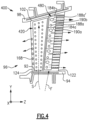
- FIG. 4 shows an airfoil 400 including a first cooling structure 420 and a second cooling structure 480, each provided by baffles.
- first cooling structure 420 may receive cooling airflow 140 from a secondary airflow path S at inner diameter end wall 92 of airfoil body 96.
- Another portion of cooling airflow F may be directed through second cooling structure 480. Since the flow direction F is opposite to that shown in FIG 3A , the positioning of the first and second holes 188a, 188b is revised.
- the airfoil 600 may be a blade 70 comprising a trailing edge 602 facing an aft direction in a gas turbine engine and leading edge 604 facing a forward direction in the gas turbine engine.
- the cooling arrangement can be used in a similar manner to the turbine vanes described above.
- Leading edge 604 and trailing edge 602 may be configured and oriented to direct airflow through engine section 68 ( FIG. 2 ).
- blade 70 may comprise a first cooling structure 620 and a second cooling structure 650 configured to remove heat from airfoil body 76.
- First cooling structure 620 may comprise one or more ribs 670, which may define one or more radial passages 672 within airfoil body 76.
- Second cooling structure 650 may comprise one or more baffles 680 which may define one or more radial passages 682 through airfoil body 76.
- Second cooling structure 650 may further comprise one or more axial passages 684 within airfoil body 76. Radial passages 682 and axial passages 684 provide control over the flow and temperature of cooling airflow 640. By controlling the temperature of cooling airflow 640 via controlling the cross-sectional area of the passage, the airfoil 600 is configured to be more uniformly cooled.
- the hybrid supply feed according to this disclosure an area bias to account for the radial component of the flow by using different effective hole sizes within each passageway.
- the up-sized area of the hybrid supply feeds forces re-distribution into the down-stream channel split trailing edge aperture.
- This disclosed technology mitigates possible negative effects from cooling system that have high internal Mach number in which lower pressure sources are required to cool large portions of the airfoil.
- Prior technology does not require a hybrid supply feed dumping into an axial channel in which the flow must fill quickly despite a strong radial component that creates a bias to one side of the channel.
- This disclosed technology allows the use of high internal baffle Mach numbers within a system design without sacrificing significant heat-transfer capability. Eliminating the radial component generated by the high internal Mach number with this technology improves cooling in downstream channels and adds additional heat transfer features (e.g., additional standoffs). The high Mach number and its inherent challenges to cooling are overcome by the disclosed arrangement.
- the disclosed design also implements additional standoffs to consume area, splitting the channels downstream and increasing internal heat transfer coefficients.
Landscapes
- Engineering & Computer Science (AREA)
- Mechanical Engineering (AREA)
- General Engineering & Computer Science (AREA)
- Turbine Rotor Nozzle Sealing (AREA)
Claims (7)
- Schaufelblatt (100; 600) zur Verwendung in einem Gasturbinentriebwerk (20), wobei das Schaufelblatt Folgendes umfasst:einen hohlen Schaufelblattkörper (76; 96), der sich in einer Sehnenrichtung (Z) von einer Vorderkante (124; 604) zu einer Hinterkante (122; 602) erstreckt und sich in einer radialen Richtung (Y) von einem Innendurchmesserende (92) zu einem Außendurchmesserende (102) erstreckt;ein Prallblech (180; 680), das in dem Schaufelblattkörper (76; 96) angeordnet ist, sich in radialer Richtung (Y) erstreckt und eine Fluidströmungsrichtung (F) bereitstellt, wobei das Prallblech (180; 680) mehrere Löcher (188) aufweist, die ein erstes und ein zweites Loch (188a, 188a') beinhaltend, die dazu konfiguriert sind, einen Kühlluftstrom (140) in der Sehnenrichtung (Z) in Richtung der Hinterkante (122; 602) des Schaufelblattkörpers (76; 96) zu leiten;einen ersten Abstandshalter (190a), der sich von dem Schaufelblattkörper (76; 96) erstreckt, um das Prallblech (180... 680) zu stützen, wobei der erste axiale Abstandshalter (190a) eine erste Länge aufweist, die einen axialen Durchgang definiert, der die mehreren Löcher (188) beinhaltet;einen zweiten Abstandshalter (190b), der eine zweite Länge aufweist, die kleiner ist als die erste Länge, wobei sich das zweite Loch (188a') relativ zu der Fluidströmungsrichtung (F) stromabwärts des ersten Lochs (188) befindet; undeine Vielzahl von Öffnungen (198), die in der Hinterkante (122) des Schaufelblattkörpers (76; 96) gebildet sind, wobei die Vielzahl von Öffnungen (198) dazu konfiguriert ist, den aus dem Schaufelblattkörper (76; 96) austretenden Kühlluftstrom (140) zu leiten,wobei die mehreren Löcher (188) mindestens ein erstes Loch (188a) und mindestens ein zweites Loch (188a') beinhalten, wobei der erste und der zweite Abstandshalter (190a, 190b) einen parallelen ersten und einen parallelen zweiten Durchlass (184a, 184b) bilden,dadurch gekennzeichnet, dassdas Schaufelblatt (100; 600) eine Rippe (170; 670) umfasst, die sich zwischen dem Innendurchmesserende (92) und dem Außendurchmesserende (102) erstreckt, um einen ersten radialen Durchgang (172; 672) von einem zweiten radialen Durchgang (182; 682) zu trennen, die dazu konfiguriert sind, mindestens einen Kühlluftstrom (140) in der radialen Richtung (Y) durch den Schaufelblattkörper (76; 96) zu leiten, wobei das Prallblech (180; 680) innerhalb des zweiten radialen Durchgangs (182; 682) angeordnet ist und die mehreren Löcher (188) in Richtung mindestens einer von einer Saugseitenwand (162) oder einer Druckseitenwand (160) des Schaufelblattkörpers (76; 96) gerichtet sind;der zweite Abstandshalter (190b) radial zwischen dem ersten und dem zweiten Loch (188a, 188a') angeordnet ist, wobei das erste Loch (188a) kleiner als das zweite Loch (188a') ist; unddas mindestens eine erste Loch (188a) das Kühlfluid (140) dem ersten Durchlass (184a) zuführt und das mindestens eine zweite Loch (188a') das Kühlfluid (140) dem zweiten Durchlass (194b) zuführt.
- Schaufelblatt (100; 600) nach Anspruch 1, wobei der erste radiale Durchgang (172) ferner eine Biegung (174) umfasst, die dazu konfiguriert ist, den Kühlluftstrom aus einer ersten Kühlstruktur (120; 620) in eine zweite Kühlstruktur (150; 650) zu richten.
- Schaufelblatt nach Anspruch 1 oder 2, umfassend ein weiteres Prallblech (420), das in dem ersten radialen Durchgang angeordnet ist.
- Schaufelblatt (100; 600) nach einem der vorhergehenden Ansprüche, wobei der Schaufelblattkörper (76; 96) durch eine von einer Turbinenleitschaufel (90) oder einer Turbinenlaufschaufel (70) bereitgestellt wird.
- Turbinenabschnitt (28) eines Gasturbinentriebwerks (20), wobei der Turbinenabschnitt (28) Folgendes umfasst:eine Laufschaufel (70), die mit einer Scheibe (74) gekoppelt ist, die dazu konfiguriert ist, sich um eine Achse (X) zu drehen;eine Leitschaufel (90), die in Bezug auf die Achse (X) stationär ist;wobei mindestens eine der Laufschaufel (70) oder der Leitschaufel (90) ein Schaufelblatt (100; 600) nach einem der Ansprüche 1 bis 3 aufweist.
- Turbinenabschnitt (28) nach Anspruch 5, wobei der Schaufelblattkörper (96) eine Turbinenleitschaufel (90) ist.
- Gasturbinentriebwerk (20), umfassend:den Turbinenabschnitt (28), der einen Kernströmungsweg (C) und mindestens einen Kühlluftstrom (140) aufweist;ein Schaufelblatt (100; 600) nach einem der Ansprüche 1 bis 4, das in dem Kernströmungsweg (C) angeordnet ist.
Applications Claiming Priority (1)
| Application Number | Priority Date | Filing Date | Title |
|---|---|---|---|
| US202163230415P | 2021-08-06 | 2021-08-06 |
Publications (2)
| Publication Number | Publication Date |
|---|---|
| EP4130433A1 EP4130433A1 (de) | 2023-02-08 |
| EP4130433B1 true EP4130433B1 (de) | 2024-12-25 |
Family
ID=82850211
Family Applications (1)
| Application Number | Title | Priority Date | Filing Date |
|---|---|---|---|
| EP22189285.4A Active EP4130433B1 (de) | 2021-08-06 | 2022-08-08 | Hybride versorgungskonfiguration für axialströmungsprallbleche |
Country Status (2)
| Country | Link |
|---|---|
| US (1) | US12371996B2 (de) |
| EP (1) | EP4130433B1 (de) |
Families Citing this family (1)
| Publication number | Priority date | Publication date | Assignee | Title |
|---|---|---|---|---|
| US12480406B2 (en) * | 2024-04-05 | 2025-11-25 | Rtx Corporation | Turbine vane for a gas turbine engine |
Family Cites Families (11)
| Publication number | Priority date | Publication date | Assignee | Title |
|---|---|---|---|---|
| US4153386A (en) * | 1974-12-11 | 1979-05-08 | United Technologies Corporation | Air cooled turbine vanes |
| JP3142850B2 (ja) * | 1989-03-13 | 2001-03-07 | 株式会社東芝 | タービンの冷却翼および複合発電プラント |
| US5259730A (en) * | 1991-11-04 | 1993-11-09 | General Electric Company | Impingement cooled airfoil with bonding foil insert |
| US5516260A (en) * | 1994-10-07 | 1996-05-14 | General Electric Company | Bonded turbine airfuel with floating wall cooling insert |
| US6428273B1 (en) * | 2001-01-05 | 2002-08-06 | General Electric Company | Truncated rib turbine nozzle |
| US7921654B1 (en) | 2007-09-07 | 2011-04-12 | Florida Turbine Technologies, Inc. | Cooled turbine stator vane |
| US10612390B2 (en) | 2017-01-26 | 2020-04-07 | United Technologies Corporation | Trailing edge pressure and flow regulator |
| US10669861B2 (en) * | 2017-02-15 | 2020-06-02 | Raytheon Technologies Corporation | Airfoil cooling structure |
| US10551327B2 (en) * | 2018-04-11 | 2020-02-04 | General Electric Company | Cooling hole inspection system |
| US10822963B2 (en) | 2018-12-05 | 2020-11-03 | Raytheon Technologies Corporation | Axial flow cooling scheme with castable structural rib for a gas turbine engine |
| US11396819B2 (en) | 2019-04-18 | 2022-07-26 | Raytheon Technologies Corporation | Components for gas turbine engines |
-
2022
- 2022-08-05 US US17/882,081 patent/US12371996B2/en active Active
- 2022-08-08 EP EP22189285.4A patent/EP4130433B1/de active Active
Also Published As
| Publication number | Publication date |
|---|---|
| US20230043718A1 (en) | 2023-02-09 |
| US12371996B2 (en) | 2025-07-29 |
| EP4130433A1 (de) | 2023-02-08 |
Similar Documents
| Publication | Publication Date | Title |
|---|---|---|
| EP2907978B1 (de) | Turbinenzwischengehäuse mit definiertem Kühlmittelverteilungsfluss | |
| EP3382149B1 (de) | Kühlstruktur für gasturbinenschaufel | |
| EP3748126B1 (de) | Komponenten für gasturbinentriebwerke | |
| EP3105437B1 (de) | Kühlung von hohlen turbinenleitschaufeln | |
| EP3396107A1 (de) | Schaufeln und umlenkkappe | |
| EP3061910B1 (de) | Gasturbinenmotor-tragfläche und entsprechendes herstellungsverfahren | |
| EP3034793B1 (de) | Gasturbinenmotorkomponente mit erhöhter kühlleistung | |
| EP3514331B1 (de) | Gekühltes schaufelblatt und zugehöriges gasturbinentriebwerk | |
| EP3783198B1 (de) | Schaufel mit rippen mit verbindungsarmen und öffnungen, die einen kühlkreislauf definieren | |
| EP3054094B1 (de) | Gasturbinenmotorturbinenschaufelablenkplatte und schlangenförmiger kühlkanal | |
| EP3617454B1 (de) | Kollektorwand mit variabler wärmeübertragung | |
| EP3597857B1 (de) | Schaufel mit geneigten hinterkantenschlitzen | |
| EP4130433B1 (de) | Hybride versorgungskonfiguration für axialströmungsprallbleche | |
| EP3561230B1 (de) | Gasturbinenmotorkomponenten mit spiralförmigen kühlstrom-hohlräumen | |
| EP3453831B1 (de) | Schaufel mit konturierten sockeln | |
| EP3508693B1 (de) | Segregierte kühlluftkanäle für turbinenschaufel | |
| US11815022B2 (en) | Platform serpentine re-supply | |
| EP2977557B1 (de) | Gekühlte schaufelstruktur und zugehöriges kühlverfahren | |
| US12392246B2 (en) | Airfoil cooling circuit | |
| EP3502417B1 (de) | Ströumungsumlenkelemente einer plattform für gasturbinenmotorkomponenten | |
| EP3819473B1 (de) | Hinterkanteneinsatz für leitschaufel | |
| EP3569819B1 (de) | Mehrfachquellenablenkplatten für gasturbinenmotorkomponenten |
Legal Events
| Date | Code | Title | Description |
|---|---|---|---|
| PUAI | Public reference made under article 153(3) epc to a published international application that has entered the european phase |
Free format text: ORIGINAL CODE: 0009012 |
|
| STAA | Information on the status of an ep patent application or granted ep patent |
Free format text: STATUS: THE APPLICATION HAS BEEN PUBLISHED |
|
| AK | Designated contracting states |
Kind code of ref document: A1 Designated state(s): AL AT BE BG CH CY CZ DE DK EE ES FI FR GB GR HR HU IE IS IT LI LT LU LV MC MK MT NL NO PL PT RO RS SE SI SK SM TR |
|
| STAA | Information on the status of an ep patent application or granted ep patent |
Free format text: STATUS: REQUEST FOR EXAMINATION WAS MADE |
|
| 17P | Request for examination filed |
Effective date: 20230801 |
|
| RBV | Designated contracting states (corrected) |
Designated state(s): AL AT BE BG CH CY CZ DE DK EE ES FI FR GB GR HR HU IE IS IT LI LT LU LV MC MK MT NL NO PL PT RO RS SE SI SK SM TR |
|
| RAP3 | Party data changed (applicant data changed or rights of an application transferred) |
Owner name: RTX CORPORATION |
|
| GRAP | Despatch of communication of intention to grant a patent |
Free format text: ORIGINAL CODE: EPIDOSNIGR1 |
|
| STAA | Information on the status of an ep patent application or granted ep patent |
Free format text: STATUS: GRANT OF PATENT IS INTENDED |
|
| INTG | Intention to grant announced |
Effective date: 20240730 |
|
| GRAS | Grant fee paid |
Free format text: ORIGINAL CODE: EPIDOSNIGR3 |
|
| GRAA | (expected) grant |
Free format text: ORIGINAL CODE: 0009210 |
|
| STAA | Information on the status of an ep patent application or granted ep patent |
Free format text: STATUS: THE PATENT HAS BEEN GRANTED |
|
| AK | Designated contracting states |
Kind code of ref document: B1 Designated state(s): AL AT BE BG CH CY CZ DE DK EE ES FI FR GB GR HR HU IE IS IT LI LT LU LV MC MK MT NL NO PL PT RO RS SE SI SK SM TR |
|
| REG | Reference to a national code |
Ref country code: GB Ref legal event code: FG4D |
|
| REG | Reference to a national code |
Ref country code: CH Ref legal event code: EP |
|
| REG | Reference to a national code |
Ref country code: DE Ref legal event code: R096 Ref document number: 602022009035 Country of ref document: DE |
|
| REG | Reference to a national code |
Ref country code: IE Ref legal event code: FG4D |
|
| REG | Reference to a national code |
Ref country code: LT Ref legal event code: MG9D |
|
| PG25 | Lapsed in a contracting state [announced via postgrant information from national office to epo] |
Ref country code: HR Free format text: LAPSE BECAUSE OF FAILURE TO SUBMIT A TRANSLATION OF THE DESCRIPTION OR TO PAY THE FEE WITHIN THE PRESCRIBED TIME-LIMIT Effective date: 20241225 |
|
| PG25 | Lapsed in a contracting state [announced via postgrant information from national office to epo] |
Ref country code: FI Free format text: LAPSE BECAUSE OF FAILURE TO SUBMIT A TRANSLATION OF THE DESCRIPTION OR TO PAY THE FEE WITHIN THE PRESCRIBED TIME-LIMIT Effective date: 20241225 |
|
| PG25 | Lapsed in a contracting state [announced via postgrant information from national office to epo] |
Ref country code: BG Free format text: LAPSE BECAUSE OF FAILURE TO SUBMIT A TRANSLATION OF THE DESCRIPTION OR TO PAY THE FEE WITHIN THE PRESCRIBED TIME-LIMIT Effective date: 20241225 |
|
| PG25 | Lapsed in a contracting state [announced via postgrant information from national office to epo] |
Ref country code: NO Free format text: LAPSE BECAUSE OF FAILURE TO SUBMIT A TRANSLATION OF THE DESCRIPTION OR TO PAY THE FEE WITHIN THE PRESCRIBED TIME-LIMIT Effective date: 20250325 |
|
| PG25 | Lapsed in a contracting state [announced via postgrant information from national office to epo] |
Ref country code: GR Free format text: LAPSE BECAUSE OF FAILURE TO SUBMIT A TRANSLATION OF THE DESCRIPTION OR TO PAY THE FEE WITHIN THE PRESCRIBED TIME-LIMIT Effective date: 20250326 Ref country code: LV Free format text: LAPSE BECAUSE OF FAILURE TO SUBMIT A TRANSLATION OF THE DESCRIPTION OR TO PAY THE FEE WITHIN THE PRESCRIBED TIME-LIMIT Effective date: 20241225 |
|
| PG25 | Lapsed in a contracting state [announced via postgrant information from national office to epo] |
Ref country code: RS Free format text: LAPSE BECAUSE OF FAILURE TO SUBMIT A TRANSLATION OF THE DESCRIPTION OR TO PAY THE FEE WITHIN THE PRESCRIBED TIME-LIMIT Effective date: 20250325 |
|
| REG | Reference to a national code |
Ref country code: NL Ref legal event code: MP Effective date: 20241225 |
|
| PG25 | Lapsed in a contracting state [announced via postgrant information from national office to epo] |
Ref country code: NL Free format text: LAPSE BECAUSE OF FAILURE TO SUBMIT A TRANSLATION OF THE DESCRIPTION OR TO PAY THE FEE WITHIN THE PRESCRIBED TIME-LIMIT Effective date: 20241225 |
|
| REG | Reference to a national code |
Ref country code: AT Ref legal event code: MK05 Ref document number: 1754315 Country of ref document: AT Kind code of ref document: T Effective date: 20241225 |
|
| PG25 | Lapsed in a contracting state [announced via postgrant information from national office to epo] |
Ref country code: SM Free format text: LAPSE BECAUSE OF FAILURE TO SUBMIT A TRANSLATION OF THE DESCRIPTION OR TO PAY THE FEE WITHIN THE PRESCRIBED TIME-LIMIT Effective date: 20241225 |
|
| PG25 | Lapsed in a contracting state [announced via postgrant information from national office to epo] |
Ref country code: PL Free format text: LAPSE BECAUSE OF FAILURE TO SUBMIT A TRANSLATION OF THE DESCRIPTION OR TO PAY THE FEE WITHIN THE PRESCRIBED TIME-LIMIT Effective date: 20241225 |
|
| PG25 | Lapsed in a contracting state [announced via postgrant information from national office to epo] |
Ref country code: ES Free format text: LAPSE BECAUSE OF FAILURE TO SUBMIT A TRANSLATION OF THE DESCRIPTION OR TO PAY THE FEE WITHIN THE PRESCRIBED TIME-LIMIT Effective date: 20241225 |
|
| PG25 | Lapsed in a contracting state [announced via postgrant information from national office to epo] |
Ref country code: IS Free format text: LAPSE BECAUSE OF FAILURE TO SUBMIT A TRANSLATION OF THE DESCRIPTION OR TO PAY THE FEE WITHIN THE PRESCRIBED TIME-LIMIT Effective date: 20250425 |
|
| PG25 | Lapsed in a contracting state [announced via postgrant information from national office to epo] |
Ref country code: PT Free format text: LAPSE BECAUSE OF FAILURE TO SUBMIT A TRANSLATION OF THE DESCRIPTION OR TO PAY THE FEE WITHIN THE PRESCRIBED TIME-LIMIT Effective date: 20250428 |
|
| PG25 | Lapsed in a contracting state [announced via postgrant information from national office to epo] |
Ref country code: EE Free format text: LAPSE BECAUSE OF FAILURE TO SUBMIT A TRANSLATION OF THE DESCRIPTION OR TO PAY THE FEE WITHIN THE PRESCRIBED TIME-LIMIT Effective date: 20241225 |
|
| PG25 | Lapsed in a contracting state [announced via postgrant information from national office to epo] |
Ref country code: RO Free format text: LAPSE BECAUSE OF FAILURE TO SUBMIT A TRANSLATION OF THE DESCRIPTION OR TO PAY THE FEE WITHIN THE PRESCRIBED TIME-LIMIT Effective date: 20241225 Ref country code: AT Free format text: LAPSE BECAUSE OF FAILURE TO SUBMIT A TRANSLATION OF THE DESCRIPTION OR TO PAY THE FEE WITHIN THE PRESCRIBED TIME-LIMIT Effective date: 20241225 |
|
| PG25 | Lapsed in a contracting state [announced via postgrant information from national office to epo] |
Ref country code: SK Free format text: LAPSE BECAUSE OF FAILURE TO SUBMIT A TRANSLATION OF THE DESCRIPTION OR TO PAY THE FEE WITHIN THE PRESCRIBED TIME-LIMIT Effective date: 20241225 |
|
| PG25 | Lapsed in a contracting state [announced via postgrant information from national office to epo] |
Ref country code: CZ Free format text: LAPSE BECAUSE OF FAILURE TO SUBMIT A TRANSLATION OF THE DESCRIPTION OR TO PAY THE FEE WITHIN THE PRESCRIBED TIME-LIMIT Effective date: 20241225 |
|
| PG25 | Lapsed in a contracting state [announced via postgrant information from national office to epo] |
Ref country code: IT Free format text: LAPSE BECAUSE OF FAILURE TO SUBMIT A TRANSLATION OF THE DESCRIPTION OR TO PAY THE FEE WITHIN THE PRESCRIBED TIME-LIMIT Effective date: 20241225 |
|
| PG25 | Lapsed in a contracting state [announced via postgrant information from national office to epo] |
Ref country code: SE Free format text: LAPSE BECAUSE OF FAILURE TO SUBMIT A TRANSLATION OF THE DESCRIPTION OR TO PAY THE FEE WITHIN THE PRESCRIBED TIME-LIMIT Effective date: 20241225 |
|
| REG | Reference to a national code |
Ref country code: DE Ref legal event code: R097 Ref document number: 602022009035 Country of ref document: DE |
|
| PG25 | Lapsed in a contracting state [announced via postgrant information from national office to epo] |
Ref country code: DK Free format text: LAPSE BECAUSE OF FAILURE TO SUBMIT A TRANSLATION OF THE DESCRIPTION OR TO PAY THE FEE WITHIN THE PRESCRIBED TIME-LIMIT Effective date: 20241225 |
|
| PGFP | Annual fee paid to national office [announced via postgrant information from national office to epo] |
Ref country code: DE Payment date: 20250724 Year of fee payment: 4 |
|
| PGFP | Annual fee paid to national office [announced via postgrant information from national office to epo] |
Ref country code: FR Payment date: 20250725 Year of fee payment: 4 |
|
| PLBE | No opposition filed within time limit |
Free format text: ORIGINAL CODE: 0009261 |
|
| STAA | Information on the status of an ep patent application or granted ep patent |
Free format text: STATUS: NO OPPOSITION FILED WITHIN TIME LIMIT |
|
| REG | Reference to a national code |
Ref country code: CH Ref legal event code: L10 Free format text: ST27 STATUS EVENT CODE: U-0-0-L10-L00 (AS PROVIDED BY THE NATIONAL OFFICE) Effective date: 20251105 |
|
| 26N | No opposition filed |
Effective date: 20250926 |
|
| REG | Reference to a national code |
Ref country code: CH Ref legal event code: H13 Free format text: ST27 STATUS EVENT CODE: U-0-0-H10-H13 (AS PROVIDED BY THE NATIONAL OFFICE) Effective date: 20260324 |