EP4130432A1 - Platform serpentine re-supply - Google Patents
Platform serpentine re-supply Download PDFInfo
- Publication number
- EP4130432A1 EP4130432A1 EP22189275.5A EP22189275A EP4130432A1 EP 4130432 A1 EP4130432 A1 EP 4130432A1 EP 22189275 A EP22189275 A EP 22189275A EP 4130432 A1 EP4130432 A1 EP 4130432A1
- Authority
- EP
- European Patent Office
- Prior art keywords
- section
- gas turbine
- turbine engine
- cooling
- compressor
- Prior art date
- Legal status (The legal status is an assumption and is not a legal conclusion. Google has not performed a legal analysis and makes no representation as to the accuracy of the status listed.)
- Pending
Links
Images


Classifications
-
- F—MECHANICAL ENGINEERING; LIGHTING; HEATING; WEAPONS; BLASTING
- F02—COMBUSTION ENGINES; HOT-GAS OR COMBUSTION-PRODUCT ENGINE PLANTS
- F02C—GAS-TURBINE PLANTS; AIR INTAKES FOR JET-PROPULSION PLANTS; CONTROLLING FUEL SUPPLY IN AIR-BREATHING JET-PROPULSION PLANTS
- F02C7/00—Features, components parts, details or accessories, not provided for in, or of interest apart form groups F02C1/00 - F02C6/00; Air intakes for jet-propulsion plants
- F02C7/12—Cooling of plants
- F02C7/16—Cooling of plants characterised by cooling medium
- F02C7/18—Cooling of plants characterised by cooling medium the medium being gaseous, e.g. air
-
- F—MECHANICAL ENGINEERING; LIGHTING; HEATING; WEAPONS; BLASTING
- F01—MACHINES OR ENGINES IN GENERAL; ENGINE PLANTS IN GENERAL; STEAM ENGINES
- F01D—NON-POSITIVE DISPLACEMENT MACHINES OR ENGINES, e.g. STEAM TURBINES
- F01D5/00—Blades; Blade-carrying members; Heating, heat-insulating, cooling or antivibration means on the blades or the members
- F01D5/12—Blades
- F01D5/14—Form or construction
- F01D5/18—Hollow blades, i.e. blades with cooling or heating channels or cavities; Heating, heat-insulating or cooling means on blades
- F01D5/187—Convection cooling
-
- F—MECHANICAL ENGINEERING; LIGHTING; HEATING; WEAPONS; BLASTING
- F01—MACHINES OR ENGINES IN GENERAL; ENGINE PLANTS IN GENERAL; STEAM ENGINES
- F01D—NON-POSITIVE DISPLACEMENT MACHINES OR ENGINES, e.g. STEAM TURBINES
- F01D25/00—Component parts, details, or accessories, not provided for in, or of interest apart from, other groups
- F01D25/08—Cooling; Heating; Heat-insulation
- F01D25/12—Cooling
-
- F—MECHANICAL ENGINEERING; LIGHTING; HEATING; WEAPONS; BLASTING
- F01—MACHINES OR ENGINES IN GENERAL; ENGINE PLANTS IN GENERAL; STEAM ENGINES
- F01D—NON-POSITIVE DISPLACEMENT MACHINES OR ENGINES, e.g. STEAM TURBINES
- F01D5/00—Blades; Blade-carrying members; Heating, heat-insulating, cooling or antivibration means on the blades or the members
- F01D5/12—Blades
- F01D5/14—Form or construction
- F01D5/18—Hollow blades, i.e. blades with cooling or heating channels or cavities; Heating, heat-insulating or cooling means on blades
-
- F—MECHANICAL ENGINEERING; LIGHTING; HEATING; WEAPONS; BLASTING
- F01—MACHINES OR ENGINES IN GENERAL; ENGINE PLANTS IN GENERAL; STEAM ENGINES
- F01D—NON-POSITIVE DISPLACEMENT MACHINES OR ENGINES, e.g. STEAM TURBINES
- F01D9/00—Stators
- F01D9/02—Nozzles; Nozzle boxes; Stator blades; Guide conduits, e.g. individual nozzles
- F01D9/04—Nozzles; Nozzle boxes; Stator blades; Guide conduits, e.g. individual nozzles forming ring or sector
- F01D9/041—Nozzles; Nozzle boxes; Stator blades; Guide conduits, e.g. individual nozzles forming ring or sector using blades
-
- F—MECHANICAL ENGINEERING; LIGHTING; HEATING; WEAPONS; BLASTING
- F02—COMBUSTION ENGINES; HOT-GAS OR COMBUSTION-PRODUCT ENGINE PLANTS
- F02C—GAS-TURBINE PLANTS; AIR INTAKES FOR JET-PROPULSION PLANTS; CONTROLLING FUEL SUPPLY IN AIR-BREATHING JET-PROPULSION PLANTS
- F02C3/00—Gas-turbine plants characterised by the use of combustion products as the working fluid
- F02C3/04—Gas-turbine plants characterised by the use of combustion products as the working fluid having a turbine driving a compressor
- F02C3/06—Gas-turbine plants characterised by the use of combustion products as the working fluid having a turbine driving a compressor the compressor comprising only axial stages
-
- F—MECHANICAL ENGINEERING; LIGHTING; HEATING; WEAPONS; BLASTING
- F02—COMBUSTION ENGINES; HOT-GAS OR COMBUSTION-PRODUCT ENGINE PLANTS
- F02C—GAS-TURBINE PLANTS; AIR INTAKES FOR JET-PROPULSION PLANTS; CONTROLLING FUEL SUPPLY IN AIR-BREATHING JET-PROPULSION PLANTS
- F02C6/00—Plural gas-turbine plants; Combinations of gas-turbine plants with other apparatus; Adaptations of gas- turbine plants for special use
- F02C6/04—Gas-turbine plants providing heated or pressurised working fluid for other apparatus, e.g. without mechanical power output
- F02C6/06—Gas-turbine plants providing heated or pressurised working fluid for other apparatus, e.g. without mechanical power output providing compressed gas
- F02C6/08—Gas-turbine plants providing heated or pressurised working fluid for other apparatus, e.g. without mechanical power output providing compressed gas the gas being bled from the gas-turbine compressor
-
- F—MECHANICAL ENGINEERING; LIGHTING; HEATING; WEAPONS; BLASTING
- F05—INDEXING SCHEMES RELATING TO ENGINES OR PUMPS IN VARIOUS SUBCLASSES OF CLASSES F01-F04
- F05D—INDEXING SCHEME FOR ASPECTS RELATING TO NON-POSITIVE-DISPLACEMENT MACHINES OR ENGINES, GAS-TURBINES OR JET-PROPULSION PLANTS
- F05D2220/00—Application
- F05D2220/30—Application in turbines
- F05D2220/32—Application in turbines in gas turbines
- F05D2220/323—Application in turbines in gas turbines for aircraft propulsion, e.g. jet engines
-
- F—MECHANICAL ENGINEERING; LIGHTING; HEATING; WEAPONS; BLASTING
- F05—INDEXING SCHEMES RELATING TO ENGINES OR PUMPS IN VARIOUS SUBCLASSES OF CLASSES F01-F04
- F05D—INDEXING SCHEME FOR ASPECTS RELATING TO NON-POSITIVE-DISPLACEMENT MACHINES OR ENGINES, GAS-TURBINES OR JET-PROPULSION PLANTS
- F05D2240/00—Components
- F05D2240/10—Stators
- F05D2240/12—Fluid guiding means, e.g. vanes
-
- F—MECHANICAL ENGINEERING; LIGHTING; HEATING; WEAPONS; BLASTING
- F05—INDEXING SCHEMES RELATING TO ENGINES OR PUMPS IN VARIOUS SUBCLASSES OF CLASSES F01-F04
- F05D—INDEXING SCHEME FOR ASPECTS RELATING TO NON-POSITIVE-DISPLACEMENT MACHINES OR ENGINES, GAS-TURBINES OR JET-PROPULSION PLANTS
- F05D2240/00—Components
- F05D2240/20—Rotors
- F05D2240/30—Characteristics of rotor blades, i.e. of any element transforming dynamic fluid energy to or from rotational energy and being attached to a rotor
-
- F—MECHANICAL ENGINEERING; LIGHTING; HEATING; WEAPONS; BLASTING
- F05—INDEXING SCHEMES RELATING TO ENGINES OR PUMPS IN VARIOUS SUBCLASSES OF CLASSES F01-F04
- F05D—INDEXING SCHEME FOR ASPECTS RELATING TO NON-POSITIVE-DISPLACEMENT MACHINES OR ENGINES, GAS-TURBINES OR JET-PROPULSION PLANTS
- F05D2240/00—Components
- F05D2240/80—Platforms for stationary or moving blades
- F05D2240/81—Cooled platforms
-
- F—MECHANICAL ENGINEERING; LIGHTING; HEATING; WEAPONS; BLASTING
- F05—INDEXING SCHEMES RELATING TO ENGINES OR PUMPS IN VARIOUS SUBCLASSES OF CLASSES F01-F04
- F05D—INDEXING SCHEME FOR ASPECTS RELATING TO NON-POSITIVE-DISPLACEMENT MACHINES OR ENGINES, GAS-TURBINES OR JET-PROPULSION PLANTS
- F05D2250/00—Geometry
- F05D2250/10—Two-dimensional
- F05D2250/18—Two-dimensional patterned
- F05D2250/185—Two-dimensional patterned serpentine-like
-
- F—MECHANICAL ENGINEERING; LIGHTING; HEATING; WEAPONS; BLASTING
- F05—INDEXING SCHEMES RELATING TO ENGINES OR PUMPS IN VARIOUS SUBCLASSES OF CLASSES F01-F04
- F05D—INDEXING SCHEME FOR ASPECTS RELATING TO NON-POSITIVE-DISPLACEMENT MACHINES OR ENGINES, GAS-TURBINES OR JET-PROPULSION PLANTS
- F05D2260/00—Function
- F05D2260/20—Heat transfer, e.g. cooling
- F05D2260/221—Improvement of heat transfer
-
- F—MECHANICAL ENGINEERING; LIGHTING; HEATING; WEAPONS; BLASTING
- F05—INDEXING SCHEMES RELATING TO ENGINES OR PUMPS IN VARIOUS SUBCLASSES OF CLASSES F01-F04
- F05D—INDEXING SCHEME FOR ASPECTS RELATING TO NON-POSITIVE-DISPLACEMENT MACHINES OR ENGINES, GAS-TURBINES OR JET-PROPULSION PLANTS
- F05D2260/00—Function
- F05D2260/20—Heat transfer, e.g. cooling
- F05D2260/232—Heat transfer, e.g. cooling characterized by the cooling medium
-
- Y—GENERAL TAGGING OF NEW TECHNOLOGICAL DEVELOPMENTS; GENERAL TAGGING OF CROSS-SECTIONAL TECHNOLOGIES SPANNING OVER SEVERAL SECTIONS OF THE IPC; TECHNICAL SUBJECTS COVERED BY FORMER USPC CROSS-REFERENCE ART COLLECTIONS [XRACs] AND DIGESTS
- Y02—TECHNOLOGIES OR APPLICATIONS FOR MITIGATION OR ADAPTATION AGAINST CLIMATE CHANGE
- Y02T—CLIMATE CHANGE MITIGATION TECHNOLOGIES RELATED TO TRANSPORTATION
- Y02T50/00—Aeronautics or air transport
- Y02T50/60—Efficient propulsion technologies, e.g. for aircraft
Definitions
- the present disclosure relates to cooling structures for gas turbine engines, and, more specifically, to airfoil cooling structures.
- a gas turbine engine typically includes a fan section, a compressor section, a combustor section, and a turbine section.
- a fan section may drive air along a bypass flow path while a compressor section may drive air along a core flow path.
- air is pressurized in the compressor section and is mixed with fuel and burned in the combustor section to generate hot combustion gases.
- the hot combustion gases flow through the turbine section, which extracts energy from the hot combustion gases to power the compressor section and other gas turbine engine loads.
- the compressor section typically includes low pressure and high pressure compressors, and the turbine section includes low pressure and high pressure turbines.
- the turbine section includes multiple stages of blades and vanes. As fluid flows through the turbine section, the flow causes the blades to rotate about an axis of rotation.
- the vanes, positioned between each row of blades, are used to redirect the flow in order to maximize the power received by the downstream blades.
- Temperatures within the turbine section may be relatively high, as the flow of fluid is received initially from the combustor section of the gas turbine engine. Cooling air may be extracted from the compressor section and used to cool the gas path components. Cooled components may include, for example, rotating blades and stator vanes in the turbine section.
- the compressor section includes a high pressure compressor section that is downstream from a low compressor section.
- a combustor section is arranged fluidly between the high pressure compressor section and a turbine section.
- the component is arranged in the turbine section, which has a first path side and a second path side. The second path side is exposed to a core flow path that extends through the compressor section, the combustor section and the turbine section.
- the component is a turbine vane.
- the component has longitudinally spaced apart forward and aft rails that support the platform.
- the first inlet is provided in the forward rail.
- the internal cooling passage is a serpentine cavity that has a pressure drop.
- the second inlet is arranged downstream of the pressure drop.
- the second inlet is provided by a cluster of holes through the cover plate.
- the serpentine cavity includes a plurality of cooling augmentation features.
- cooling augmentation features include at least one of trip strips, pin fins and chevrons.
- cooling augmentation features are arranged fluidly between the first and second inlets.
- the first and second cooling fluids are provided by bleed air from the high pressure compressor section.
- a gas turbine engine that includes a compressor section that includes a high pressure compressor section downstream from a low compressor section.
- the high pressure compressor section provides first and second compressor stages that are configured to respectively provide bleed air that supplies first and second cooling fluids.
- the first compressor stage has a higher pressure than the second compressor stage.
- the gas turbine engine also includes a combustor section that is arranged fluidly between the high pressure compressor section and a turbine section.
- a core flow path extends through the compressor section, the combustor section and the turbine section.
- the gas turbine engine further includes a component that is arranged in the turbine section and has a platform with an internal cooling passage that is fed by first and second inlets that respectively receive fluid from the first and second cooling sources. The second inlet is downstream from the first inlet.
- the component is a turbine vane.
- the turbine vane includes a hollow airfoil that is configured to receive a third cooling fluid from the compressor section and different from the first and second cooling fluids.
- the turbine vane has a first path side and a second path side.
- the second path side is exposed to the core flow path.
- the turbine vane has longitudinally spaced apart forward and aft rails that support the platform.
- the first inlet is provided in the forward rail.
- a cover plate is secured over the serpentine on the first gas path side.
- the cover plate provides the second inlet.
- the second inlet is provided by a cluster of holes through the cover plate.
- the serpentine cavity includes a plurality of cooling augmentation features.
- the cooling augmentation features include at least one of trip strips, pin fins and chevrons.
- the cooling augmentation features are arranged fluidly between the first and second inlets.
- FIG. 1 schematically illustrates a gas turbine engine 20.
- the gas turbine engine 20 is disclosed herein as a two-spool turbofan that generally incorporates a fan section 22, a compressor section 24, a combustor section 26 and a turbine section 28.
- the fan section 22 drives air along a bypass flow path B in a bypass duct defined within a housing 15 such as a fan case or nacelle, and also drives air along a core flow path C for compression and communication into the combustor section 26 then expansion through the turbine section 28.
- the exemplary engine 20 generally includes a low speed spool 30 and a high speed spool 32 mounted for rotation about an engine central longitudinal axis X relative to an engine static structure 36 via several bearing systems 38. It should be understood that various bearing systems 38 at various locations may alternatively or additionally be provided, and the location of bearing systems 38 may be varied as appropriate to the application.
- the low speed spool 30 generally includes an inner shaft 40 that interconnects, a first (or low) pressure compressor 44 and a first (or low) pressure turbine 46.
- the inner shaft 40 is connected to the fan 42 through a speed change mechanism, which in exemplary gas turbine engine 20 is illustrated as a geared architecture 48 to drive a fan 42 at a lower speed than the low speed spool 30.
- the high speed spool 32 includes an outer shaft 50 that interconnects a second (or high) pressure compressor 52 and a second (or high) pressure turbine 54.
- a combustor 56 is arranged in the exemplary gas turbine 20 between the high pressure compressor 52 and the high pressure turbine 54.
- a mid-turbine frame 57 of the engine static structure 36 may be arranged generally between the high pressure turbine 54 and the low pressure turbine 46.
- the mid-turbine frame 57 further supports bearing systems 38 in the turbine section 28.
- the inner shaft 40 and the outer shaft 50 are concentric and rotate via bearing systems 38 about the engine central longitudinal axis X which is collinear with their longitudinal axes.
- the core airflow is compressed by the low pressure compressor 44 then the high pressure compressor 52, mixed and burned with fuel in the combustor 56, then expanded through the high pressure turbine 54 and low pressure turbine 46.
- the mid-turbine frame 57 includes airfoils 59 which are in the core airflow path C.
- the turbines 46, 54 rotationally drive the respective low speed spool 30 and high speed spool 32 in response to the expansion.
- gear system 48 may be located aft of the low pressure compressor, or aft of the combustor section 26 or even aft of turbine section 28, and fan 42 may be positioned forward or aft of the location of gear system 48.
- the fan section 22 of the engine 20 is designed for a particular flight condition -- typically cruise at about 0.8 Mach and about 35,000 feet (10,668 meters).
- the flight condition of 0.8 Mach and 35,000 ft (10,668 meters), with the engine at its best fuel consumption - also known as "bucket cruise Thrust Specific Fuel Consumption ('TSFC')" - is the industry standard parameter of lbm of fuel being burned divided by lbf of thrust the engine produces at that minimum point.
- 'TSFC' Thrust Specific Fuel Consumption
- “Low fan pressure ratio” is the pressure ratio across the fan blade alone, without a Fan Exit Guide Vane (“FEGV”) system.
- the low fan pressure ratio as disclosed herein according to one non-limiting embodiment is less than about 1.45, or more narrowly greater than or equal to 1.25.
- Low corrected fan tip speed is the actual fan tip speed in ft/sec divided by an industry standard temperature correction of [(Tram °R) / (518.7 o R)] 0.5 .
- the "Low corrected fan tip speed" as disclosed herein according to one non-limiting embodiment is less than about 1150.0 ft / second (350.5 meters/second), and can be greater than or equal to 1000.0 ft / second (304.8 meters/second).
- Engine section 68 which may be a turbine section 28, includes a circumferential array of blades 70 coupled about a circumference of a generally circular disk 74.
- Disk 74 may be disposed radially inward of core flowpath C and centered on the rotation axis of the gas turbine engine.
- Disk 74 with blades 70 may be configured to rotate about engine central longitudinal axis X.
- Each blade 70 may include an airfoil body 76 with a platform disposed at an inner diameter end wall 72 of the blade 70.
- a disk cavity 80 may be defined between a forward disk and an aft disk. Upstream (forward) and downstream (aft) of blades 70 are circumferential arrays of vanes 90 configured to guide core flowpath C through the engine section 68.
- Each vane 90 may include an airfoil body 96 with an inner diameter platform 94 disposed at an inner diameter end wall 92 of vane 90 and with an outer diameter platform 98 disposed at an outer diameter end wall 102 of vane 90.
- Outer diameter platform 98 may be coupled to engine case structure 36.
- Inner diameter platform 94 and/or outer diameter platform 98 may be coupled to or integral with vane 90.
- first, second and third cooling sources S1, S2, S3 supply cooling fluid to the turbine section. These cooling sources are fed bleed air from the compressor section, for example, from one or more compressor stages of the HPC 52.
- vane 90 may comprise an internal cooling system to convectively remove heat from the airfoil body 96 of vane 90.
- a secondary airflow path may be defined within disk cavity 80 and may contain a third cooling fluid from third cooling source S3.
- This third cooling fluid may be routed in any suitable manner.
- the cooling fluid such as bleed air, may be introduced into a cavity 112 of inner diameter platform 94 through an orifice 114 in inner diameter platform 94.
- the coolant may flow into a vane via a vane outer diameter cavity.
- Blade 70 may similarly include an internal cooling system.
- the component cooled according to the disclosed platform serpentine resupply configuration may be arranged differently than shown and described.
- the component 150 can include one or more platforms 152 and one or more airfoils 154 that extend from the platform(s) 152.
- the component 150 includes an inner diameter platform 152A and an outer diameter platform 152B as well as two airfoils 154A, 154B that extend between the inner and outer platforms 152A, 152B.
- vane doublet it should be understood that vane singlets or other vane assemblies may benefit from the teachings of this disclosure, and that non-airfoil components, such as BOAS or transition ducts, may also benefit from these teachings.
- the platform(s) 152 include a leading edge portion 156 providing a forward rail, a trailing edge portion 158 providing an aft rail, and opposing mate faces 160, 162.
- the platform(s) 152 axially extend between the leading edge portion 156 and the trailing edge portion 158 and circumferentially extend between the opposing mate faces 160, 162.
- the opposing mate faces 160, 162 can be mounted relative to corresponding mate faces of adjacent components of a gas turbine engine to provide a full ring assembly, such as a full ring vane assembly that can be circumferentially disposed about the engine centerline longitudinal axis X (see FIG. 1 ).
- the platforms can also include a first path side (for example, a non-gas path side) 164 and a second path side (for example a gas path side) 166.
- a first path side for example, a non-gas path side
- a second path side for example a gas path side
- 166 may establish an outer boundary of the core flow path C of the gas turbine engine 20.
- One or both of the platforms 152 can also include a platform cooling circuit 168 for cooling the platform 152.
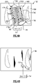
- a platform cooling circuit 168 is illustrated in FIG. 4A .
- the platform cooling circuit 168 is disposed on the non-gas path side 164 of the platform 152.
- the platform 152 could be representative of either an inner diameter platform or an outer diameter platform of a vane, or could be a platform of some other component, including but not limited to, a blade or a BOAS.
- the exemplary platform cooling circuit 168 provides a serpentine cavity 178 including generally longitudinal portions 178A, 178B, 178C fluidly connected by bends 178D, 178E.
- One or more of these portions may include cooling augmentation features 200 to further improve cooling to the platform 152.
- Cooling augmentation features include, for example, chevrons, trip strips, pin fins or other turbulent flow-inducing features that enhance heat transfer.
- a cover plate 180 positioned at the non-gas path side 164 of the platform 152 over the serpentine cavity. It should be understood that the platform cooling circuit 168 could be configured to provide a variety of flow paths based upon the cooling desired from this internal cooling passage and is not necessarily limited to the particular configuration shown in FIG. 3 . Additionally, a separate cover plate 180 can instead be integrally formed with the platform 152, such that a wax core or other technique is used to form the internal cooling passage.
- the cover plate 180 ( FIG. 4B ) is positioned to cover the serpentine cavity 178 to define an enclosed cooling passage therein.
- the cover plate 180 may be brazed or welded onto the non-gas path side 164 of the platform 152.
- the cover plate 180 may be shaped similar to the serpentine cavity 178.
- the serpentine cavity 178 is fed by a first inlet 190 that is supplied a first cooling fluid from the first cooling source S1.
- a first cooling fluid from the first cooling source S1.
- the bends e.g., bend 178E
- the bends provide desirable locations to resupply the serpentine cavity 178 with cooling fluid by avoiding disrupting the high heat transfer developed flow in the longer passages. Because the flow has to turn and disrupt this developed flow to some extent regardless, the turn is a good location to introduce higher pressure air while maintaining optimal heat transfer in the longer channels.
- the cover plate 180 may include one or more openings provided by a cluster of holes 194 that extend through the cover plate 180 to serve as a second inlet 192 to resupply a low pressure region 196 of the serpentine cavity 178.
- the resupplied low pressure region 196 corresponds with the bend 178E.
- the second inlet 192 which is downstream from the first inlet 190, is fed by a second cooling fluid from the second cooling source S2.
- the high pressure compressor section 52 and two of its first and second compressor stages respectively provide bleed air supplying the first and second cooling fluids. Since the first compressor stage has a higher pressure than the second compressor stage, the second cooling fluid will be at a lower pressure and temperature than the first cooling fluid.
- the second cooling fluid is at a higher pressure than the pressure at the low pressure region 196. Cooling fluid may exit the serpentine cavity 178 in any suitable location, for example, at one of the opposing mate faces 160, 162. Thus, when the second cooling fluid is introduced into a region that has dropped sufficiently in pressure, the benefits of both a temperature reduction as well as a pressure increase are realized.
Abstract
Description
- The present disclosure relates to cooling structures for gas turbine engines, and, more specifically, to airfoil cooling structures.
- A gas turbine engine typically includes a fan section, a compressor section, a combustor section, and a turbine section. A fan section may drive air along a bypass flow path while a compressor section may drive air along a core flow path. In general, during operation, air is pressurized in the compressor section and is mixed with fuel and burned in the combustor section to generate hot combustion gases. The hot combustion gases flow through the turbine section, which extracts energy from the hot combustion gases to power the compressor section and other gas turbine engine loads. The compressor section typically includes low pressure and high pressure compressors, and the turbine section includes low pressure and high pressure turbines. The turbine section includes multiple stages of blades and vanes. As fluid flows through the turbine section, the flow causes the blades to rotate about an axis of rotation. The vanes, positioned between each row of blades, are used to redirect the flow in order to maximize the power received by the downstream blades.
- Temperatures within the turbine section may be relatively high, as the flow of fluid is received initially from the combustor section of the gas turbine engine. Cooling air may be extracted from the compressor section and used to cool the gas path components. Cooled components may include, for example, rotating blades and stator vanes in the turbine section.
- Both the compressor and turbine sections of the gas turbine engine may include alternating rows of rotating blades and stationary vanes that extend into the core flow path of the gas turbine engine. For example, in the turbine section, turbine blades rotate to extract energy from the hot combustion gases that are communicated along the core flow path of the gas turbine engine. The turbine vanes prepare the airflow for the next set of blades. These blades and vanes are examples of components that may need cooled by a dedicated source of cooling airflow in order to withstand the relatively high temperatures of the hot combustion gases that are communicated along the core flow path.
- In one aspect, there is provided a gas turbine engine that includes a compressor section that provides first and second compressor stages that are configured to respectively provide first and second cooling fluids. The first compressor stage has a higher pressure than the second compressor stage. The gas turbine engine further includes a component that has platform with an internal cooling passage fed by first and second inlets that respectively receive fluid from the first and second cooling sources. The second inlet is downstream from the first inlet.
- In an embodiment of the above, the compressor section includes a high pressure compressor section that is downstream from a low compressor section. A combustor section is arranged fluidly between the high pressure compressor section and a turbine section. The component is arranged in the turbine section, which has a first path side and a second path side. The second path side is exposed to a core flow path that extends through the compressor section, the combustor section and the turbine section.
- In a further embodiment of any of the above, the component is a turbine vane.
- In a further embodiment of any of the above, the turbine vane includes a hollow airfoil that is configured to receive a third cooling fluid from the compressor section and different from the first and second cooling fluids.
- In a further embodiment of any of the above, the component has longitudinally spaced apart forward and aft rails that support the platform. The first inlet is provided in the forward rail.
- In a further embodiment of any of the above, the internal cooling passage is a serpentine cavity that has a pressure drop. The second inlet is arranged downstream of the pressure drop.
- In a further embodiment of any of the above, a cover plate is secured over the serpentine on the first gas path side. The cover plate provides the second inlet.
- In a further embodiment of any of the above, the second inlet is provided by a cluster of holes through the cover plate.
- In a further embodiment of any of the above, the serpentine cavity includes a plurality of cooling augmentation features.
- In a further embodiment of any of the above, the cooling augmentation features include at least one of trip strips, pin fins and chevrons.
- In a further embodiment of any of the above, the cooling augmentation features are arranged fluidly between the first and second inlets.
- In a further embodiment of any of the above, the first and second cooling fluids are provided by bleed air from the high pressure compressor section.
- In another aspect, which the Applicant expressly reserves the right to claim independently, there is provided a gas turbine engine that includes a compressor section that includes a high pressure compressor section downstream from a low compressor section. The high pressure compressor section provides first and second compressor stages that are configured to respectively provide bleed air that supplies first and second cooling fluids. The first compressor stage has a higher pressure than the second compressor stage. The gas turbine engine also includes a combustor section that is arranged fluidly between the high pressure compressor section and a turbine section. A core flow path extends through the compressor section, the combustor section and the turbine section. The gas turbine engine further includes a component that is arranged in the turbine section and has a platform with an internal cooling passage that is fed by first and second inlets that respectively receive fluid from the first and second cooling sources. The second inlet is downstream from the first inlet.
- In an embodiment of the above, the component is a turbine vane.
- In a further embodiment of any of the above, the turbine vane includes a hollow airfoil that is configured to receive a third cooling fluid from the compressor section and different from the first and second cooling fluids.
- In a further embodiment of any of the above, the turbine vane has a first path side and a second path side. The second path side is exposed to the core flow path. The turbine vane has longitudinally spaced apart forward and aft rails that support the platform. The first inlet is provided in the forward rail.
- In a further embodiment of any of the above, the internal cooling passage is a serpentine cavity that has a pressure drop. The second inlet is arranged downstream of the pressure drop.
- In a further embodiment of any of the above, a cover plate is secured over the serpentine on the first gas path side. The cover plate provides the second inlet.
- In a further embodiment of any of the above, the second inlet is provided by a cluster of holes through the cover plate.
- In a further embodiment of any of the above, the serpentine cavity includes a plurality of cooling augmentation features. The cooling augmentation features include at least one of trip strips, pin fins and chevrons. The cooling augmentation features are arranged fluidly between the first and second inlets.
- The disclosure can be further understood by reference to the following detailed description when considered in connection with the accompanying drawings wherein:
-
FIG. 1 illustrates a cross-sectional view of an exemplary gas turbine engine, in accordance with various embodiments; -
FIG. 2 illustrates an engine section including example airfoils, such as a blade and a vane of an exemplary gas turbine engine, according to various embodiments; -
FIG. 3 illustrates a component that can be incorporated into a gas turbine engine. -
FIGS. 4A and 4B depict top views respectively of a platform serpentine cooling passage and a cover plate. - The embodiments, examples and alternatives of the preceding paragraphs, the claims, or the following description and drawings, including any of their various aspects or respective individual features, may be taken independently or in any combination. Features described in connection with one embodiment are applicable to all embodiments, unless such features are incompatible.
-
Figure 1 schematically illustrates agas turbine engine 20. Thegas turbine engine 20 is disclosed herein as a two-spool turbofan that generally incorporates afan section 22, acompressor section 24, acombustor section 26 and aturbine section 28. Thefan section 22 drives air along a bypass flow path B in a bypass duct defined within ahousing 15 such as a fan case or nacelle, and also drives air along a core flow path C for compression and communication into thecombustor section 26 then expansion through theturbine section 28. Although depicted as a two-spool turbofan gas turbine engine in the disclosed non-limiting embodiment, it should be understood that the concepts described herein are not limited to use with two-spool turbofans as the teachings may be applied to other types of turbine engines including three-spool architectures. - The
exemplary engine 20 generally includes alow speed spool 30 and ahigh speed spool 32 mounted for rotation about an engine central longitudinal axis X relative to an enginestatic structure 36 viaseveral bearing systems 38. It should be understood that various bearingsystems 38 at various locations may alternatively or additionally be provided, and the location of bearingsystems 38 may be varied as appropriate to the application. - The
low speed spool 30 generally includes an inner shaft 40 that interconnects, a first (or low)pressure compressor 44 and a first (or low)pressure turbine 46. The inner shaft 40 is connected to thefan 42 through a speed change mechanism, which in exemplarygas turbine engine 20 is illustrated as a gearedarchitecture 48 to drive afan 42 at a lower speed than thelow speed spool 30. Thehigh speed spool 32 includes anouter shaft 50 that interconnects a second (or high)pressure compressor 52 and a second (or high)pressure turbine 54. Acombustor 56 is arranged in theexemplary gas turbine 20 between thehigh pressure compressor 52 and thehigh pressure turbine 54. Amid-turbine frame 57 of the enginestatic structure 36 may be arranged generally between thehigh pressure turbine 54 and thelow pressure turbine 46. Themid-turbine frame 57 furthersupports bearing systems 38 in theturbine section 28. The inner shaft 40 and theouter shaft 50 are concentric and rotate via bearingsystems 38 about the engine central longitudinal axis X which is collinear with their longitudinal axes. - The core airflow is compressed by the
low pressure compressor 44 then thehigh pressure compressor 52, mixed and burned with fuel in thecombustor 56, then expanded through thehigh pressure turbine 54 andlow pressure turbine 46. Themid-turbine frame 57 includesairfoils 59 which are in the core airflow path C. Theturbines low speed spool 30 andhigh speed spool 32 in response to the expansion. It will be appreciated that each of the positions of thefan section 22,compressor section 24,combustor section 26,turbine section 28, and fandrive gear system 48 may be varied. For example,gear system 48 may be located aft of the low pressure compressor, or aft of thecombustor section 26 or even aft ofturbine section 28, andfan 42 may be positioned forward or aft of the location ofgear system 48. - The
engine 20 in one example is a high-bypass geared aircraft engine. In a further example, theengine 20 bypass ratio is greater than about six (6), with an example embodiment being greater than about ten (10), and can be less than or equal to about 18.0, or more narrowly can be less than or equal to 16.0. The gearedarchitecture 48 is an epicyclic gear train, such as a planetary gear system or other gear system, with a gear reduction ratio of greater than about 2.3. The gear reduction ratio may be less than or equal to 4.0. Thelow pressure turbine 46 has a pressure ratio that is greater than about five. The low pressure turbine pressure ratio can be less than or equal to 13.0, or more narrowly less than or equal to 12.0. In one disclosed embodiment, theengine 20 bypass ratio is greater than about ten (10:1), the fan diameter is significantly larger than that of thelow pressure compressor 44, and thelow pressure turbine 46 has a pressure ratio that is greater than about five 5:1.Low pressure turbine 46 pressure ratio is pressure measured prior to an inlet oflow pressure turbine 46 as related to the pressure at the outlet of thelow pressure turbine 46 prior to an exhaust nozzle. The gearedarchitecture 48 may be an epicycle gear train, such as a planetary gear system or other gear system, with a gear reduction ratio of greater than about 2.3:1 and less than about 5:1. It should be understood, however, that the above parameters are only exemplary of one embodiment of a geared architecture engine and that the present invention is applicable to other gas turbine engines including direct drive turbofans. - A significant amount of thrust is provided by the bypass flow B due to the high bypass ratio. The
fan section 22 of theengine 20 is designed for a particular flight condition -- typically cruise at about 0.8 Mach and about 35,000 feet (10,668 meters). The flight condition of 0.8 Mach and 35,000 ft (10,668 meters), with the engine at its best fuel consumption - also known as "bucket cruise Thrust Specific Fuel Consumption ('TSFC')" - is the industry standard parameter of lbm of fuel being burned divided by lbf of thrust the engine produces at that minimum point. The engine parameters described above and those in this paragraph are measured at this condition unless otherwise specified. "Low fan pressure ratio" is the pressure ratio across the fan blade alone, without a Fan Exit Guide Vane ("FEGV") system. The low fan pressure ratio as disclosed herein according to one non-limiting embodiment is less than about 1.45, or more narrowly greater than or equal to 1.25. "Low corrected fan tip speed" is the actual fan tip speed in ft/sec divided by an industry standard temperature correction of [(Tram °R) / (518.7 oR)]0.5. The "Low corrected fan tip speed" as disclosed herein according to one non-limiting embodiment is less than about 1150.0 ft / second (350.5 meters/second), and can be greater than or equal to 1000.0 ft / second (304.8 meters/second). - Referring now to
FIG. 1 and toFIG. 2 , according to various embodiments, each oflow pressure compressor 44,high pressure compressor 52,low pressure turbine 46, andhigh pressure turbine 54 ingas turbine engine 20 may comprise one or more stages or sets of rotating blades and one or more stages or sets of stationary vanes axially interspersed with the associated blade stages but non-rotating about engine central longitudinal axis X. Each compressor stage and turbine stage may comprise multiple interspersed stages of blades 70 and vanes 90. The blades 70 rotate about engine central longitudinal axis X, while the vanes 90 remain stationary with respect to engine central longitudinal axis X. Blades 70 and vanes 90 may be referred to asairfoils 100. For example,FIG. 2 schematically shows, by example, a portion of anengine section 68, which is illustrated as aturbine section 28 ofgas turbine engine 20. - With reference to
FIG. 2 , a schematic view of a portion ofengine section 68 is shown, in accordance with various embodiments.Engine section 68, which may be aturbine section 28, includes a circumferential array of blades 70 coupled about a circumference of a generallycircular disk 74.Disk 74 may be disposed radially inward of core flowpath C and centered on the rotation axis of the gas turbine engine.Disk 74 with blades 70 may be configured to rotate about engine central longitudinal axis X. Each blade 70 may include anairfoil body 76 with a platform disposed at an innerdiameter end wall 72 of the blade 70. Adisk cavity 80 may be defined between a forward disk and an aft disk. Upstream (forward) and downstream (aft) of blades 70 are circumferential arrays of vanes 90 configured to guide core flowpath C through theengine section 68. - Each vane 90 may include an airfoil body 96 with an
inner diameter platform 94 disposed at an innerdiameter end wall 92 of vane 90 and with anouter diameter platform 98 disposed at an outerdiameter end wall 102 of vane 90.Outer diameter platform 98 may be coupled toengine case structure 36.Inner diameter platform 94 and/orouter diameter platform 98 may be coupled to or integral with vane 90. - The
turbine section 28, particularly the stages immediately downstream from thecombustor section 26, experience extreme heat such that that cooling must be provided to one or more components of theturbine section 28, for example, vanes, platforms and/or blade outer air seals (BOAS). In the example shown inFIGS 1-3 , first, second and third cooling sources S1, S2, S3 supply cooling fluid to the turbine section. These cooling sources are fed bleed air from the compressor section, for example, from one or more compressor stages of theHPC 52. - In various embodiments and with reference to
FIG. 3 and still toFIG. 2 , vane 90 may comprise an internal cooling system to convectively remove heat from the airfoil body 96 of vane 90. A secondary airflow path may be defined withindisk cavity 80 and may contain a third cooling fluid from third cooling source S3. This third cooling fluid may be routed in any suitable manner. The cooling fluid, such as bleed air, may be introduced into acavity 112 ofinner diameter platform 94 through anorifice 114 ininner diameter platform 94. In various embodiments, the coolant may flow into a vane via a vane outer diameter cavity. Blade 70 may similarly include an internal cooling system. However, it should be understood that the component cooled according to the disclosed platform serpentine resupply configuration may be arranged differently than shown and described. -
FIG. 3 illustrates acomponent 150 that can be incorporated into a gas turbine engine, such as thegas turbine engine 20 ofFIG. 1 . In this embodiment, thecomponent 150 is a turbine vane, such as the vane 90 illustrated inFIG. 2 . However, this disclosure is not limited to turbine vanes and could extend to other components of thegas turbine engine 20, including but not limited to, compressor blades and vanes, turbine blades, blade outer air seals (BOAS), mid-turbine frames, transition ducts, or any other component that extends within the core flow path C. - The
component 150 can include one ormore platforms 152 and one or more airfoils 154 that extend from the platform(s) 152. In this particular embodiment, thecomponent 150 includes aninner diameter platform 152A and anouter diameter platform 152B as well as twoairfoils outer platforms - The platform(s) 152 include a
leading edge portion 156 providing a forward rail, a trailingedge portion 158 providing an aft rail, and opposing mate faces 160, 162. The platform(s) 152 axially extend between theleading edge portion 156 and the trailingedge portion 158 and circumferentially extend between the opposing mate faces 160, 162. The opposing mate faces 160, 162 can be mounted relative to corresponding mate faces of adjacent components of a gas turbine engine to provide a full ring assembly, such as a full ring vane assembly that can be circumferentially disposed about the engine centerline longitudinal axis X (seeFIG. 1 ). - The platforms can also include a first path side (for example, a non-gas path side) 164 and a second path side (for example a gas path side) 166. In other words, when the
component 150 is mounted within thegas turbine engine 20, thenon-gas path side 164 is positioned on a non-core flow path side of thecomponent 150, while thegas path side 166 may establish an outer boundary of the core flow path C of thegas turbine engine 20. - One or both of the
platforms 152 can also include aplatform cooling circuit 168 for cooling theplatform 152. One exemplaryplatform cooling circuit 168 is illustrated inFIG. 4A . Theplatform cooling circuit 168 is disposed on thenon-gas path side 164 of theplatform 152. In this embodiment, theplatform 152 could be representative of either an inner diameter platform or an outer diameter platform of a vane, or could be a platform of some other component, including but not limited to, a blade or a BOAS. - The exemplary
platform cooling circuit 168 provides aserpentine cavity 178 including generallylongitudinal portions bends platform 152. Cooling augmentation features include, for example, chevrons, trip strips, pin fins or other turbulent flow-inducing features that enhance heat transfer. - A
cover plate 180 positioned at thenon-gas path side 164 of theplatform 152 over the serpentine cavity. It should be understood that theplatform cooling circuit 168 could be configured to provide a variety of flow paths based upon the cooling desired from this internal cooling passage and is not necessarily limited to the particular configuration shown inFIG. 3 . Additionally, aseparate cover plate 180 can instead be integrally formed with theplatform 152, such that a wax core or other technique is used to form the internal cooling passage. - In this embodiment, the cover plate 180 (
FIG. 4B ) is positioned to cover theserpentine cavity 178 to define an enclosed cooling passage therein. Thecover plate 180 may be brazed or welded onto thenon-gas path side 164 of theplatform 152. Thecover plate 180 may be shaped similar to theserpentine cavity 178. - The
serpentine cavity 178 is fed by afirst inlet 190 that is supplied a first cooling fluid from the first cooling source S1. As the first cooling fluid flows from thefirst inlet 190 to the downstream portions, there is a pressure drop from a high pressure region H to a relatively lower pressure region L. The pressure may become low as the flow travels further downstream. The bends (e.g., bend 178E), which may be downstream from cooling augmentation features 200, provide desirable locations to resupply theserpentine cavity 178 with cooling fluid by avoiding disrupting the high heat transfer developed flow in the longer passages. Because the flow has to turn and disrupt this developed flow to some extent regardless, the turn is a good location to introduce higher pressure air while maintaining optimal heat transfer in the longer channels. - In a non-limiting embodiment, the
cover plate 180 may include one or more openings provided by a cluster ofholes 194 that extend through thecover plate 180 to serve as asecond inlet 192 to resupply alow pressure region 196 of theserpentine cavity 178. In the example, the resuppliedlow pressure region 196 corresponds with thebend 178E. Thesecond inlet 192, which is downstream from thefirst inlet 190, is fed by a second cooling fluid from the second cooling source S2. In this manner, the highpressure compressor section 52 and two of its first and second compressor stages respectively provide bleed air supplying the first and second cooling fluids. Since the first compressor stage has a higher pressure than the second compressor stage, the second cooling fluid will be at a lower pressure and temperature than the first cooling fluid. But, the second cooling fluid is at a higher pressure than the pressure at thelow pressure region 196. Cooling fluid may exit theserpentine cavity 178 in any suitable location, for example, at one of the opposing mate faces 160, 162. Thus, when the second cooling fluid is introduced into a region that has dropped sufficiently in pressure, the benefits of both a temperature reduction as well as a pressure increase are realized. - It should also be understood that although a particular component arrangement is disclosed in the illustrated embodiment, other arrangements will benefit herefrom. Although particular step sequences are shown, described, and claimed, it should be understood that steps may be performed in any order, separated or combined unless otherwise indicated and will still benefit from the embodiments of the present invention.
- Although the different examples have specific components shown in the illustrations, embodiments of this invention are not limited to those particular combinations. It is possible to use some of the components or features from one of the examples in combination with features or components from another one of the examples.
- Although an example embodiment has been disclosed, a worker of ordinary skill in this art would recognize that certain modifications would come within the scope of the claims. For that reason, the following claims should be studied to determine their true scope and content.
Claims (14)
- A gas turbine engine (20), comprising:a compressor section (24) providing first and second compressor stages configured to respectively provide first and second cooling fluids, the first compressor stage having a higher pressure than the second compressor stage; anda component (150) having platform (152; 152A; 152B) with an internal cooling passage (168) fed by first and second inlets (190, 192) respectively receiving fluid from the first and second cooling sources (S1, S2), the second inlet (192) downstream from the first inlet (190).
- The gas turbine engine (20) of claim 1, wherein the compressor section (24) includes a high pressure compressor section (52) downstream from a low compressor section (44), and a combustor section (26) arranged fluidly between the high pressure compressor section (52) and a turbine section (28), the component (150) arranged in the turbine section (28), the component (150) having a first path side (164) and a second path side (166), the second path side (166) exposed to a core flow path (C) that extends through the compressor section (24), the combustor section (26) and the turbine section (28).
- The gas turbine engine (20) of claim 2, wherein the component (150) is a turbine vane (90).
- The gas turbine engine (20) of claim 3, wherein the turbine vane (90) includes a hollow airfoil (154) configured to receive a third cooling fluid from the compressor section (24) and different from the first and second cooling fluids.
- The gas turbine engine (20) of any of claims 2 to 4, wherein the component (150) has longitudinally spaced apart forward and aft rails (156, 158) supporting the platform (152; 152A; 152B), the first inlet (190) provided in the forward rail (156).
- The gas turbine engine (20) of any of claims 2 to 5, wherein the internal cooling passage (168) is a serpentine cavity (178) having a pressure drop, and the second inlet (192) is arranged downstream of the pressure drop.
- The gas turbine engine (20) of claim 6, wherein a cover plate (180) is secured over the serpentine cavity (178) on the first path side (164), the cover plate (180) providing the second inlet (192).
- The gas turbine engine (20) of claim 7, wherein the second inlet (192) is provided by a cluster of holes (194) through the cover plate (180).
- The gas turbine engine (20) of any of claims 6 to 8, wherein the serpentine cavity (178) includes a plurality of cooling augmentation features (200).
- The gas turbine engine (20) of claim 9, wherein the cooling augmentation features (200) include at least one of trip strips, pin fins and chevrons.
- The gas turbine engine (20) of claim 9 or 10, wherein the cooling augmentation features (2000) are arranged fluidly between the first and second inlets (190, 192).
- The gas turbine engine (20) of any of claims 2 to 11, wherein the first and second cooling fluids are provided by bleed air from the high pressure compressor section (52).
- The gas turbine engine (20) of any preceding claim, wherein:the compressor section (24) includes a high pressure compressor section (52) downstream from a low compressor section (44), the high pressure compressor section (52) providing the first and second compressor stages, wherein the first and second compressor stages are configured to respectively provide bleed air supplying the first and second cooling fluids;the gas turbine engine comprises a combustor section (26) arranged fluidly between the high pressure compressor section (52) and a turbine section (28), and a core flow path (C) that extends through the compressor section (24), the combustor section (26) and the turbine section (28); andwherein the component (150) is arranged in the turbine section (28).
- The gas turbine engine (20) of claim 13, wherein the component (150) is a turbine vane (90), wherein the turbine vane (90) has a first path side (164) and a second path side (166), the second path side (166) exposed to the core flow path (C), the turbine vane (90) has longitudinally spaced apart forward and aft rails (156, 158) supporting the platform (152; 152A; 152B), the first inlet (190) provided in the forward rail (156).
Applications Claiming Priority (1)
| Application Number | Priority Date | Filing Date | Title |
|---|---|---|---|
| US202163230424P | 2021-08-06 | 2021-08-06 |
Publications (1)
| Publication Number | Publication Date |
|---|---|
| EP4130432A1 true EP4130432A1 (en) | 2023-02-08 |
Family
ID=82850420
Family Applications (1)
| Application Number | Title | Priority Date | Filing Date |
|---|---|---|---|
| EP22189275.5A Pending EP4130432A1 (en) | 2021-08-06 | 2022-08-08 | Platform serpentine re-supply |
Country Status (2)
| Country | Link |
|---|---|
| US (1) | US11815022B2 (en) |
| EP (1) | EP4130432A1 (en) |
Citations (2)
| Publication number | Priority date | Publication date | Assignee | Title |
|---|---|---|---|---|
| US20140047843A1 (en) * | 2012-08-15 | 2014-02-20 | Michael Leslie Clyde Papple | Platform cooling circuit for a gas turbine engine component |
| CN210948909U (en) * | 2019-11-27 | 2020-07-07 | 上海电气燃气轮机有限公司 | Cooling system, cold air chamber sealing structure and sealing partition plate of gas turbine |
Family Cites Families (10)
| Publication number | Priority date | Publication date | Assignee | Title |
|---|---|---|---|---|
| US4798515A (en) * | 1986-05-19 | 1989-01-17 | The United States Of America As Represented By The Secretary Of The Air Force | Variable nozzle area turbine vane cooling |
| DE19733148C1 (en) * | 1997-07-31 | 1998-11-12 | Siemens Ag | Cooling device for gas turbine initial stage |
| DE10122695A1 (en) * | 2001-05-10 | 2002-11-21 | Siemens Ag | Process for cooling a gas turbine and gas turbine plant |
| US7306424B2 (en) * | 2004-12-29 | 2007-12-11 | United Technologies Corporation | Blade outer seal with micro axial flow cooling system |
| US8096747B2 (en) * | 2008-02-01 | 2012-01-17 | General Electric Company | Apparatus and related methods for turbine cooling |
| US9500099B2 (en) | 2012-07-02 | 2016-11-22 | United Techologies Corporation | Cover plate for a component of a gas turbine engine |
| US9303518B2 (en) | 2012-07-02 | 2016-04-05 | United Technologies Corporation | Gas turbine engine component having platform cooling channel |
| EP3023596B1 (en) | 2014-11-20 | 2019-01-02 | United Technologies Corporation | Internally cooled turbine platform |
| US10287906B2 (en) * | 2016-05-24 | 2019-05-14 | Rolls-Royce North American Technologies Inc. | Turbine shroud with full hoop ceramic matrix composite blade track and seal system |
| US10662780B2 (en) | 2018-01-09 | 2020-05-26 | United Technologies Corporation | Double wall turbine gas turbine engine vane platform cooling configuration with baffle impingement |
-
2022
- 2022-08-05 US US17/882,114 patent/US11815022B2/en active Active
- 2022-08-08 EP EP22189275.5A patent/EP4130432A1/en active Pending
Patent Citations (2)
| Publication number | Priority date | Publication date | Assignee | Title |
|---|---|---|---|---|
| US20140047843A1 (en) * | 2012-08-15 | 2014-02-20 | Michael Leslie Clyde Papple | Platform cooling circuit for a gas turbine engine component |
| CN210948909U (en) * | 2019-11-27 | 2020-07-07 | 上海电气燃气轮机有限公司 | Cooling system, cold air chamber sealing structure and sealing partition plate of gas turbine |
Also Published As
| Publication number | Publication date |
|---|---|
| US11815022B2 (en) | 2023-11-14 |
| US20230037659A1 (en) | 2023-02-09 |
Similar Documents
| Publication | Publication Date | Title |
|---|---|---|
| US10808546B2 (en) | Gas turbine engine airfoil trailing edge suction side cooling | |
| US20140219778A1 (en) | Gas turbine engine airfoil with vane platform cooling passage | |
| EP2977555B1 (en) | Airfoil platform with cooling channels | |
| US10465542B2 (en) | Gas turbine engine turbine vane baffle and serpentine cooling passage | |
| EP3392458A1 (en) | Turbine with upstream facing tangential onboard injector for | |
| US20160003077A1 (en) | Gas turbine engine turbine vane rail seal | |
| EP3514332A1 (en) | Dual-wall impingement cavity for components of gas turbine engines | |
| EP3112596A1 (en) | Gas turbine engine airfoil with bi-axial skin cooling passage and corresponding gas turbine engine | |
| EP3561229B1 (en) | Gas turbine engine component with platform cover plate | |
| EP3514331B1 (en) | Cooled airfoil and corresponding gas turbine engine | |
| US10787912B2 (en) | Spiral cavities for gas turbine engine components | |
| EP3896259A1 (en) | Turbine vane having dual source cooling | |
| EP4130432A1 (en) | Platform serpentine re-supply | |
| WO2014159575A1 (en) | Gas turbine engine multi-vaned stator cooling configuration | |
| US10697310B2 (en) | Multiple source impingement baffles for gas turbine engine components | |
| US10961862B2 (en) | Fatigue resistant blade outer air seal | |
| US11073023B2 (en) | Airfoil having improved throughflow cooling scheme and damage resistance | |
| US20200182072A1 (en) | Baffle for components of gas turbine engines | |
| US20190195086A1 (en) | Platform flow turning elements for gas turbine engine components | |
| US20180291748A1 (en) | Resupply hole of cooling air into gas turbine blade serpentine passage |
Legal Events
| Date | Code | Title | Description |
|---|---|---|---|
| PUAI | Public reference made under article 153(3) epc to a published international application that has entered the european phase |
Free format text: ORIGINAL CODE: 0009012 |
|
| STAA | Information on the status of an ep patent application or granted ep patent |
Free format text: STATUS: THE APPLICATION HAS BEEN PUBLISHED |
|
| AK | Designated contracting states |
Kind code of ref document: A1 Designated state(s): AL AT BE BG CH CY CZ DE DK EE ES FI FR GB GR HR HU IE IS IT LI LT LU LV MC MK MT NL NO PL PT RO RS SE SI SK SM TR |
|
| STAA | Information on the status of an ep patent application or granted ep patent |
Free format text: STATUS: REQUEST FOR EXAMINATION WAS MADE |
|
| 17P | Request for examination filed |
Effective date: 20230731 |
|
| RBV | Designated contracting states (corrected) |
Designated state(s): AL AT BE BG CH CY CZ DE DK EE ES FI FR GB GR HR HU IE IS IT LI LT LU LV MC MK MT NL NO PL PT RO RS SE SI SK SM TR |
|
| RAP3 | Party data changed (applicant data changed or rights of an application transferred) |
Owner name: RTX CORPORATION |