EP4129887B1 - Vehicle lift and method for lifting vehicles - Google Patents
Vehicle lift and method for lifting vehicles Download PDFInfo
- Publication number
- EP4129887B1 EP4129887B1 EP22189136.9A EP22189136A EP4129887B1 EP 4129887 B1 EP4129887 B1 EP 4129887B1 EP 22189136 A EP22189136 A EP 22189136A EP 4129887 B1 EP4129887 B1 EP 4129887B1
- Authority
- EP
- European Patent Office
- Prior art keywords
- screw
- column
- rotary member
- electric motor
- lift
- Prior art date
- Legal status (The legal status is an assumption and is not a legal conclusion. Google has not performed a legal analysis and makes no representation as to the accuracy of the status listed.)
- Active
Links
Images




Classifications
-
- B—PERFORMING OPERATIONS; TRANSPORTING
- B66—HOISTING; LIFTING; HAULING
- B66F—HOISTING, LIFTING, HAULING OR PUSHING, NOT OTHERWISE PROVIDED FOR, e.g. DEVICES WHICH APPLY A LIFTING OR PUSHING FORCE DIRECTLY TO THE SURFACE OF A LOAD
- B66F7/00—Lifting frames, e.g. for lifting vehicles; Platform lifts
- B66F7/10—Lifting frames, e.g. for lifting vehicles; Platform lifts with platforms supported directly by jacks
- B66F7/12—Lifting frames, e.g. for lifting vehicles; Platform lifts with platforms supported directly by jacks by mechanical jacks
- B66F7/14—Lifting frames, e.g. for lifting vehicles; Platform lifts with platforms supported directly by jacks by mechanical jacks screw operated
-
- B—PERFORMING OPERATIONS; TRANSPORTING
- B66—HOISTING; LIFTING; HAULING
- B66F—HOISTING, LIFTING, HAULING OR PUSHING, NOT OTHERWISE PROVIDED FOR, e.g. DEVICES WHICH APPLY A LIFTING OR PUSHING FORCE DIRECTLY TO THE SURFACE OF A LOAD
- B66F7/00—Lifting frames, e.g. for lifting vehicles; Platform lifts
- B66F7/28—Constructional details, e.g. end stops, pivoting supporting members, sliding runners adjustable to load dimensions
-
- B—PERFORMING OPERATIONS; TRANSPORTING
- B66—HOISTING; LIFTING; HAULING
- B66F—HOISTING, LIFTING, HAULING OR PUSHING, NOT OTHERWISE PROVIDED FOR, e.g. DEVICES WHICH APPLY A LIFTING OR PUSHING FORCE DIRECTLY TO THE SURFACE OF A LOAD
- B66F7/00—Lifting frames, e.g. for lifting vehicles; Platform lifts
- B66F7/02—Lifting frames, e.g. for lifting vehicles; Platform lifts with platforms suspended from ropes, cables, or chains or screws and movable along pillars
Definitions
- the present invention relates to a vehicle lift and a method for lifting vehicles.
- the present invention may be used in the automotive field for servicing vehicles.
- the present invention may be employed for lifting various types of vehicles, including cars, trucks, agricultural vehicle.
- Column lifts comprise one or more vertical support columns, each of which carries a carriage provided with a pair of orientable/extensible arms: the ends of the arm have pads which may be adjusted height-wise and configured to receive - resting thereon - the vehicle to be lifted.
- Each carriage may be displaced using an electromechanical system consisting of an electric motor active on a screw/nut screw system; the screw is arranged in the column and engaged to the nut screw associated with the carriage: the rotation of the screw generated by the electric motor allows the displacement of the nut screw and the resulting vertical sliding of the carriage along a column.
- the electric motor is arranged on the top of the column.
- the electromechanical system comprises a screw and a relative electric motor for each column or it may comprise a screw for each column and only one electric motor: the screws are mechanically connected by a drive system.
- the Applicant observed that the electric motor of the electromechanical system, so as to able to guarantee the lifting of the vehicles, is subjected to high workloads which often generate overheating in the motor.
- a first example of column lift is described in the United States patent application No. US 4,076,216 A .
- Such lift has an electric motor arranged in the head of the column with the drive shaft thereof aligned with the screw; the drive shaft is connected by means of friction to an end of the screw.
- the electric motor is housed in a protection guard, provided with one or more heat dissipation fins arranged outside the guard.
- the Applicant observed that the presence of fins outside the guard does not allow to appropriately dissipate the heat generated by the electric motor.
- the solution described in the patent application No. US 4,076,216 A forces the user to extended machine downtime so as to allow the cooling of the electric motor and avoid damaging the latter, a condition which significantly affects the productivity and reliability of the lift.
- a second example of lift is described in the French patent application No. FR2374256A1 .
- Such lift comprises two columns, each of which carries an electric motor connected to the screw of the respective column: the two electric motors are controlled by means of an electronic unit configured to keep the carriages substantially at the same height.
- the electric motor is arranged at the head of the column and it is without any outer protection/guard.
- Each electric motor is arranged beside the screw of the respective column and connected to the screw through an indirect drive system consisting of a drive pulley fixed to the drive shaft connected - by means of a belt - to a driven pulley fixed to the screw: the belt/pulley drive system allows to transfer the rotary motion of the motor to the screw.
- Similar two-column lifts are described in the patent applications No. CN110182716A and No. CH635555A5 .
- a third example of lift is described in the patent application No. WO 2006/086941 A2 , and discloses a vehicle lift having the features according to the preamble of the independent claim 1.
- Such lift comprises a column in which there is housed an electric motor whose drive shaft is connected, through a drive system, to a screw/nut screw system arranged beside the column configured to displace a carriage along the column.
- the Applicant observed that also the lifts described in the second and third example have a structure which is not capable of cooling the electric motor which is therefore subjected to overheating, a condition which, as described above for the first example, significantly affects the productivity and reliability of the lift.
- the object of the present invention is to overcome at least one of the drawbacks and/or limitations of the previous solutions.
- An object of the present invention is to provide a lift having a simple and compact structure, that has low production costs while being at the same time structurally robust, capable of lifting vehicles continuously and quickly. Furthermore, an object of the present invention is to provide a lift capable of guaranteeing the effective and quick lifting of a wide range of transport means. Furthermore, another object of the present invention is to provide a lift capable of operating in a safe and reliable manner, in particular capable of lifting vehicles without damaging the latter or components of the lift.
- vertical used relating to components of the lift, refers to a use condition thereof during which the lift carries out, or may be used for, a procedure for lifting/lowering a vehicle with respect to the ground.
- the lift described and claimed hereinafter may comprise/use at least one control unit 50 designed to control the operating conditions provided by the lift and/or the control of the method steps for lifting a vehicle.
- the control unit 50 may be single unit one or it may consist of a plurality of distinct control units depending on the design choices and operative needs.
- the expression control unit is used to indicate an electronic component which may comprise at least one of: a digital processor (CPU), an analogue circuit, or a combination of one or more digital processors with one or more analogue circuits.
- the control unit may be "configured” or "programmed” to perform some steps: this may basically be obtained using any means which allows to configure or programme the control unit.
- one or more programmes may be stored in appropriate memory banks connected to the CPU or to the CPUs; the programme or programmes contain instructions which, when run by the CPU or by the CPUs, programme or configure the control unit to perform the operations described relating to the control unit.
- the control unit is or comprises an analogue circuit, then the circuit of the control unit may be designed to include a circuit configured, in use, to process electrical signals so as to perform the steps relative to the control unit.
- Parts of the method described herein may be obtained by means of a data processing unit, or control unit, which may be technically replaced with one or more computers designed to run a portion of a software or firmware programme loaded on a storage medium.
- Such software programme may be written in any programming language of the known type. If two or more, the computers may be connected to each other through a data connection such that the computing capacity thereof is shared in any manner; therefore, the computers may even be installed in geographically different positions, creating a distributed computing environment through the aforementioned data connection.
- the data processing unit, or control unit may be a general-purpose processor configured to run one or more parts of the process identified in the present disclosure through the software or firmware programme, or it may be an ASIC or dedicated process or an FPGA, specifically programmed to at least partly carry out operations of the method described herein.
- the storage medium may be non-transitory and it may be inside or outside the processor, or control unit, or data processing unit, and it may - specifically - be a memory geographically arranged remotely with respect to the computer. Furthermore, the storage medium may be physically split into several portions, or in form of cloud, and the software or firmware programme may physically provide for portions stored on storage portions geographically split from each other.
- Reference number 1 indicates a vehicle lift.
- the lift may be used in the automotive industry for servicing various types of vehicles, including cars, trucks, and agricultural vehicles.
- the lift 1 comprises at least one column 2 extending, in use, along a vertical direction between a base portion 2a and a top portion 2b (see for example figure 1 ).
- the column 2 defines the vertical element for supporting the lift, configured to support the vehicle suspended with respect to the ground; the column 2 may be fixed to the ground, for example using screw/bolt systems.
- the column 2 may comprise a base plate 20, optionally made of metal material, configured to be fixed to the ground and from which there emerges, over the entire extension of the column 2, a support frame 21, also optionally made of metal material.
- the base plate 20 comprises a plurality of holes 20a configured to receive a fastening screw suitable to allow the locking of the plate 20 and - as a result - the entire column to the ground.
- the support frame 21 is joined as a single piece to the base plate 20 and it defines - therein - a seat 22 ( figure 3 ) configured to receive - engaged thereto - one or more components of the lift 1 which will be better described hereinafter.
- the support frame 21 has a cross-section with constant profile, optionally having a C-shaped or substantially V-shaped profile (see for example the top view of figure 3 ).
- the support frame 21 is obtained by means of one or more sheet layers made of metal material.
- the column 2 may further comprise, optionally at the top portion 2b, a support plate 30: the support plate 30 is juxtaposed to the base plate 20 with respect to the frame 21 and it essentially defines an end element of the column 2.
- the lift 1 comprises only one column 2 or it may comprise a plurality of columns 2 distinct and spaced from each other.
- Figure 1 shows, by way of non-limiting example, a lift 1 comprising two columns 2 (a first and a second column): the columns are arranged spaced from each other and they extend along a vertical direction, parallel to each other. The columns are spaced apart so as to allow to position, interposed with respect to each other, at least one vehicle.
- the lift 1 comprises at least one carriage 3 ( figure 1 ) slidably movable along the column 2.
- the lift 1 comprises a carriage 3 for each column 2; the carriage 3 defines the movable element of the lift 1 suitable to carry the vehicle in contact to move it (in particular lift it and lower it) with respect to the ground, for example so as to allow an operator to work on the vehicle.
- the carriage 3 is movable along the column 2 approaching and moving away with respect to the base portion 2a (optionally with respect to the plate 20).
- the carriage 3 comprises at least one lifting arm configured to contact a vehicle, optionally the bodywork of the vehicle, so as to allow the lifting thereof; the arm of the carriage lies substantially along a plane orthogonal to an extension direction of the column 2.
- the arm may be of the orientable type, that is rotatably movable around an axis Y parallel to the extension direction of the column 2: such axis Y may be arranged outside the support frame 21 for example as shown in figure 3 . Additionally or alternatively, the arm may be of the extensible type, that is configured to vary the length thereof.
- the carriage 3 may comprise two lifting arms 31, 32 ( figure 1 ) both configured to contact a vehicle, optionally the body of the vehicle, so as to allow the lifting thereof.
- the lifting arms 31, 32 lie substantially on a single plane orthogonal to the extension direction of the column.
- At least one of said lifting arms 31, 32 may be of the orientable type, that is rotatably movable around a respective axis Y parallel to an extension direction of the column.
- the lift 1 shown in the attached figures has a first and second arm 31, 32 both of the orientable type; additionally or alternatively, at least one of said lifting arms 31, 32 may be of the extensible type; by way of non-limiting example, the attached figures show a first non-extensible orientable arm 31 and a second arm 32 which is both orientable and of the extensible type.
- each arm carries - at the end - a support foot configured to directly contact the bodywork of the vehicle; in particular, the first and second arm carry - at the end - respective feet 31a, 32a which may be adjusted height-wise.
- the lift 1 may comprise a first and a second column. Should the lift 1 comprise only one column, it has only one carriage 3 as described above.
- figure 1 shows a lift 1 having a first and a second column each of which comprises a carriage 3 as described above.
- the lift further comprises a movement system 4 ( figures 4 and 5 ) associated with at least one column 2 and configured to move the carriage 3 along said column.
- the movement system 4 is configured to move each carriage 3 along the respective column.
- Detailed hereinafter is a non-limiting embodiment of the movement system 4 associated with only one column 2.
- the movement system 4 comprises a screw 5, of the worm screw type, extending along at least one extension section of the column 2 and rotatably movable around an axis X, parallel to the extension direction of the column 2; in detail, the axis X passes through the centre of the screw, that is it is concentric to the screw 5: basically, the screw 5 is configured to rotate on itself around an axis thereof passing through the centre of the screw.
- the screw 5 is housed in the seat 22 of the support frame 21 and it extends along the entire frame, starting from the base portion 2a, up to the top portion 2b.
- the screw 5 extends between a first and a second end: the first end of the screw 5 is arranged at the base portion 2a of the column 2 while the second end of the screw 5 is arranged at the top portion of the column 2.
- the screw 5 is hinged - at the first end - to the base plate 20 while - at the second end - it is hinged to the support plate 30 ( figures 4 and 5 ). In this manner, the screw 5 is engaged to the column 2 and movable with respect to said column around the axis X.
- the movement system 4 further comprises a nut screw 6 concentrically engaged to the screw 5: the nut screw is and movable along the screw, following the rotation of said screw 5 around the axis X: the nut screw 6 is engaged - on one side- to the screw 5 and - on the other side - it is integrally joined with carriage 3 so that the nut screw 6 and carriage 3 are movable integrally joined along the screw 5 and - as a result - along the column 2.
- the movement system 4 further comprises at least one electric motor 7 kinematically connected to screw 5 so as to allow the rotation of said screw.
- the electric motor 7 is used to control the rotation of the screw 5 so that the nut screw and carriage 3 may slide along the column 2.
- the electric motor 7 may have a power rating comprised between 0.5 kW and 10 kW.
- the electric motor 7 is carried by the column 2 and it may be arranged, at at least one of the end portions: for example, at the base portion 2a or the top portion 2b. In the attached figures, the electric motor 7 is arranged, by way of non-limiting example, at the top portion 2b.
- the electric motor 7 may be directly constrained to the support plate 30, beside the screw 5.
- the electric motor 7 is arranged outside the frame 21 of the column 2, below the support plate 30, that is so that said electric motor 7 is interposed between the support plate 30 and the base plate 20.
- the movement system 4 further comprises one rotary member 8 rotatably integrally joined with at least one of the electric motor 7 and the screw 5.
- the rotary member 8 may be directly carried by a drive shaft of the electric motor 7 or directly carried by the screw 5; the attached figures show, by way of non-limiting example, a lift 1 wherein the rotary member 8 is directly fixed at an end portion of the screw 5 (optionally at the second end of the screw).
- the rotary member 8 kinematically connects the electric motor 7 to the screw 5: the rotary member 8 is configured to transfer a rotary motion from the electric motor 7 to the screw 5 and, consequently, moving the carriage 3 along the column 2.
- the rotary member 8 may be made of plastic and/or metal material.
- the rotary member 8 may be at least partly, optionally entirely, made of at least one of the following materials: steel, aluminium, plastic, composite material or a combination of the preceding materials.
- the rotary member 8 has a plurality of blades 9 configured to generate, during the rotation of the rotary member 8, an airflow suitable to impact one or more components of the lift, for example further components of the movement system 4.
- the rotary member 8 may be configured to generate, during the rotation of the rotary member 8, a (cooling) airflow suitable to at least partly impact at least the electric motor 7 and/or one or more further components of the movement system 4; for example, the movement system 4 may comprise one or more bearings suitable to support the electric motor 7, the screw 5, the nut screw 6 the rotation of the rotary member 8 allows to generate a cooling airflow suitable to impact one or more of said components so as to allow the cooling thereof.
- the rotary member 8 besides acting as a member for transmitting motion between the electric motor 7 and screw 5, the rotary member 8 essentially acts as a cooling device, for example for the electric motor 7, optionally (more generally) for one or more further components of the movement system 4.
- the rotary member 8 rotates - as a result (given that it is rotatably integrally joined with at least one of the electric motor 7 and the screw 5) - and, thanks to the plurality of blades 9 - generates an airflow which allows to dissipate the heat, e.g., generated by the electric motor 7, during the operation thereof.
- the rotary member 8 comprises a number of blades 9 equal to or greater than 3, optionally equal to or comprised between 3 and 10, even more optionally equal to or comprised between 3 and 7.
- At least one blade 9, optionally each blade 9, according to a cross-section, has a wing profile, for example of the concave-convex or flat-convex or laminar concave-convex type. Thanks to the wing profile, the blade/blades is/are capable of generating an airflow suitable to impact the electric motor 7 to cool it.
- the attached figures show a movement system 4 comprising a rotary member 8 fixed on the screw 5: a drive member 10 connected to the rotary member 8 by means of a drag element 11 is fixed on the drive shaft 7a of the electric motor 7.
- the rotary member 8 essentially defines a driven member, driven in rotation by the drive member 10 (element directly driven in rotation by the electric motor 7).
- the rotary member 8 may comprise a pulley, optionally with dual-seat (see the two seats 9 of the pulley shown in figures 7 and 9 ); the pulley has a central hub 91 configured to allow to fix the pulley to the screw 5: the central hub 91 and the (dual) seat 92 of the pulley are joined together as a single piece by means of a plurality of blades 9.
- the drive member 10 may comprise a pulley, optionally with dual-seat, which is suitable to cooperate with a drag element 11 comprising at least one belt ( figures 4 and 5 ).
- the rotary member 8, the driven member 10 and the drag element 11 define an indirect belt drive system.
- the members 8 and 10 respectively comprise a crown gear and a pinion or a gear transmission cannot be ruled out.
- the rotary member 8 is configured to define an impeller fan also capable of acting as a member for transmitting motion.
- the rotary member 8 and the drive member 10 are constrained to the support plate 30, in particular on the side opposite to the electric motor 7 ( figures 4 and 5 ); the drag element 11 is also arranged juxtaposed to the electric motor 7 with respect to the support plate 30.
- the possibility of providing an electric motor 7 on the same side as the support plate 30 on which also the rotary member 8 and, optionally, the drive member 10 are arranged, cannot be ruled out.
- the lift 1 may comprise a casing 15 engaged to the column 2 and in which there is at least partly housed, the electric motor 7, and optionally one or more components of the movement system 4 (for example one of more bearings for supporting the rotary member 8).
- the casing 15 may be arranged at the top portion of the column 2; the casing 15 may therefore be used to define, cooperating with the column 2, a channel configured to allow the through-flow of an airflow.
- the channel may comprise:
- the airflow flowing through from the channel, from the inlet 15a to the outlet 15b, may be generated by the rotation of the rotary member 8 during the operation of the electric motor 7.
- the operation of the electric motor 7 drives in rotation the rotary member 8 which, thanks to the blades 9, allows to generate an airflow in the channel: any component arranged in the channel is configured to be impacted (therefore cooled) by the airflow which may be generated by the rotary member 8.
- the electric motor 7 (optionally the bearing for supporting the rotary member 8) is arranged in the channel: in this manner, the electric motor 7, during the operation thereof, is impacted by an airflow which allows to dissipate the heat which may be generated by the electric motor to avoid unwanted overheating.
- the casing 15 may comprise a top panel 18 arranged at the top portion 2b of the column 2 from which there emerges, in the direction of the base portion 2a of the same column, a side wall 19: the top panel 18 and side wall 19 delimit a compartment 16 configured to house the electric motor 7.
- the electric motor 7 is entirely housed in the compartment 16 of the casing, together with the rotary member 8 (optionally also the support plate 30, the drive member 10 and the drag element 11 are entirely arranged in the compartment 16): as observable in figure 10 , the support plate 30 is entirely housed in the compartment 16 of the casing 15, spaced from and facing the top panel 18.
- the top portion 2b of the column, together with the casing 15, define the channel: the side wall 19 of the casing 15 delimits a single passage opening traversed by the column portion 2 and by the screw 5 of the movement system 4 (the top portion of the column is arranged in the compartment 16).
- the passage opening is faced toward the base portion 2a: said passage opening, cooperating with the frame 21 of the column 2, defines at least one of the inlet 15a and the outlet 15b of the channel.
- the casing 15 has at least one through access configured to define at least one of the inlet 15a and the outlet 15b of the channel; the at least one through access is defined on at least one of the top panel 18 and the side wall 19 of the casing.
- the through access has been shown, by way of non-limiting example, only on the side wall 19 (the top panel 18 has been schematised, by way of non-limiting example, as without through accesses); obviously, the possibility of providing a through access on at least one of the side wall 19 and the top panel 18 cannot be ruled out.
- the casing 15 may comprise a plurality of through accesses.
- the accompanying figures show, in a non-limiting way, the inlet 15a of the channel defined on the casing (optionally defined by the through accesses of the casing 15) and an outlet defined by the cooperation between the casing 15 and the frame 21 of the column 2.
- the arrangement of the inlet and outlet depends on the rotation direction of the rotary member 8; for example:
- the airflow allows to cool the electric motor 7, arranged in the channel.
- the possibility of generating an airflow configured to cool - besides the electric motor 7 - any other component arranged in the channel, such as for example a bearing for supporting the rotary member 8 cannot be ruled out.
- the possibility of arranging an electric motor outside the casing 15 cannot be ruled out; the airflow which may be generated by the rotary member 8 (arranged inside the casing 15) would allow to impact only the components arranged in the channel, such as for example a bearing for supporting the rotary member 8.
- the lift 1 may comprise at least one sensor 40 ( figures 4-6 and 10 ), for example an inductive sensor, carried by the support plate 30.
- the sensor 40 is configured to emit a representative signal relating to the rotary member 8, for example at least one of: a rotation speed of the rotary member 8, an angular position of the rotary member 8 with respect to an initial reference position, a number of rotations carried out by the rotary member 8 with respect to an initial reference position, a rotation speed of the screw 5, angular position of the screw 5 with respect to an initial reference position, a number of rotations carried out by the screw 5 with respect to an initial reference position.
- the lift 1 may comprise at least one control unit 50 connected to the sensor 40 and configured to receive and process the representative signal emitted by the latter and, as a function of said signal, determine a position and/or a sliding speed of the carriage 3 along the column 2. Furthermore, the control unit 50 is active to control the electric motor 7 and, as a function of the representative signal emitted by the sensor 40, it may control the electric motor 7 to manage the position and sliding speed of the latter along the column 2.
- the lift 1 may comprise a first and a second column, each according to the column 2 described above that is comprising a base plate 20, a support frame 21, optionally a support plate 30.
- the lift 1 may comprise two electric motors 7, that is a first and second electric motor, each of which is carried by a respective column 2 and it is configured to move a respective carriage 3.
- the movement system 4 may comprise a first screw (according to the screw 5 described above) engaged to a first nut screw (according to the nut screw 6 described above): the first nut screw is engaged - on one side - to the first screw and - on the other side - to a first carriage carried by the first column.
- first rotary member Fixed on the first screw is a first rotary member (according to the rotary member 8 described above): the first rotary member is driven in rotation by a first drag element (according to the drag element 11 described above) connected to a first drive member (according to the drive member 10 described above) fixed on the first electric motor (according to the electric motor 7 described above). Basically, the first carriage 3 is moved by the first electric motor.
- the movement system 4 may comprise a second screw (according to the screw 5 described above) engaged to a second nut screw (according to the nut screw 6 described above): the second nut screw is engaged - on one side - to the second screw and - on the other side - to a second carriage carried by the second column.
- Fixed on the second screw is a second rotary member (according to the rotary member 8 described above): the second rotary member is driven in rotation by a second drag element (according to the drag element 11 described above) connected to a second drive member (according to the drive member 10 described above) fixed on second electric motor (according to the electric motor 7 described above).
- the second carriage 3 is moved by the first electric motor.
- each carriage may be independently moved by a respective electric motor.
- the lift 1 may comprise a casing 15 for each electric motor.
- the casing 15, cooperating with the respective column 2 is configured to define the channel suitable to allow the through-flow of air between the inlet 15a and the outlet 15b, useful for cooling one or more components of the movement system 4, for example of the respective electric motor 7.
- the control unit 50 may be connected to both electric motors for synchronising, in a per se known manner, the movement of the carriages along the first and second column.
- the lift 1 may comprise only one electric motor 7 sole associated with one of the first and the second column.
- the column 2 carrying the electric motor is of the type described above while the first electric motor may solely comprise: the column, carrying a carriage 3, a screw 5 housed in the column 2, a nut screw 6 slidably engaged to the carriage 3 and to the screw 5.
- the screws 5 of the two columns are connected to each other in motion, in a per se known manner, by means of a drive system, for example a chain drive system: thus, the activation of the single electric motor 7 may allow the movement of the screws of the first and second column.
- the lift 1 may comprise a casing 15 for each electric motor 7, that is a single casing 15 for the single electric motor.
- an object of the present invention is a method of lifting vehicles using the e lift according to the description reported above and/or according to the attached claims.
- the method envisages the following steps:
- the rotary member 8 rotates and generates an airflow suitable to impact one or more components of the movement system 4, for example at least partly the electric motor 7 and/or a bearing for supporting the rotary member 8.
- the rotary member 8 rotates to generate - inside the channel - an airflow flowing in from the inlet 15a and flowing out from the outlet 15b suitable to impact one or more components of the movement system, for example at least partly the electric motor 7 and/or a bearing for supporting the rotary member 8.
- rotary member 8 may be used for moving the screw 5 and the corresponding carriage 3 and, at the same time, for generating a cooling airflow (for example for the electric motor 7); the rotary member 8 allows to provide a reliable lift capable of operating continuously without the need for machine downtime. Basically, the possibility to move the carriages 3 continuously significantly increases the productivity of the lift. Furthermore, it should be observed that the use of a rotary member 8 capable of generating a cooling airflow (for example suitable to impact the electric motor 7) allows to provide a lift 1 capable of avoiding unwanted overheating, therefore providing an extremely safe and reliable lift.
Landscapes
- Life Sciences & Earth Sciences (AREA)
- Engineering & Computer Science (AREA)
- Geology (AREA)
- Mechanical Engineering (AREA)
- Structural Engineering (AREA)
- Transmission Devices (AREA)
- Types And Forms Of Lifts (AREA)
- Automobile Manufacture Line, Endless Track Vehicle, Trailer (AREA)
- Vehicle Waterproofing, Decoration, And Sanitation Devices (AREA)
Description
- The present invention relates to a vehicle lift and a method for lifting vehicles. The present invention may be used in the automotive field for servicing vehicles. However, the present invention may be employed for lifting various types of vehicles, including cars, trucks, agricultural vehicle.
- Column lifts comprise one or more vertical support columns, each of which carries a carriage provided with a pair of orientable/extensible arms: the ends of the arm have pads which may be adjusted height-wise and configured to receive - resting thereon - the vehicle to be lifted. Each carriage may be displaced using an electromechanical system consisting of an electric motor active on a screw/nut screw system; the screw is arranged in the column and engaged to the nut screw associated with the carriage: the rotation of the screw generated by the electric motor allows the displacement of the nut screw and the resulting vertical sliding of the carriage along a column. The electric motor is arranged on the top of the column. The electromechanical system comprises a screw and a relative electric motor for each column or it may comprise a screw for each column and only one electric motor: the screws are mechanically connected by a drive system. However, the Applicant observed that the electric motor of the electromechanical system, so as to able to guarantee the lifting of the vehicles, is subjected to high workloads which often generate overheating in the motor.
- A first example of column lift is described in the United States patent application No.
US 4,076,216 A . Such lift has an electric motor arranged in the head of the column with the drive shaft thereof aligned with the screw; the drive shaft is connected by means of friction to an end of the screw. The electric motor is housed in a protection guard, provided with one or more heat dissipation fins arranged outside the guard. The Applicant observed that the presence of fins outside the guard does not allow to appropriately dissipate the heat generated by the electric motor. In addition, the solution described in the patent application No.US 4,076,216 A forces the user to extended machine downtime so as to allow the cooling of the electric motor and avoid damaging the latter, a condition which significantly affects the productivity and reliability of the lift. - A second example of lift is described in the French patent application No.
FR2374256A1 CN110182716A and No.CH635555A5 - A third example of lift is described in the patent application No.
WO 2006/086941 A2 , and discloses a vehicle lift having the features according to the preamble of theindependent claim 1. Such lift comprises a column in which there is housed an electric motor whose drive shaft is connected, through a drive system, to a screw/nut screw system arranged beside the column configured to displace a carriage along the column. - However, the Applicant observed that also the lifts described in the second and third example have a structure which is not capable of cooling the electric motor which is therefore subjected to overheating, a condition which, as described above for the first example, significantly affects the productivity and reliability of the lift.
- Although the known lifts are used for lifting vehicles, the Applicant observed that such lifts are not devoid of limitations and drawbacks, therefore being subject to improvement from various standpoints.
- Therefore, the object of the present invention is to overcome at least one of the drawbacks and/or limitations of the previous solutions.
- An object of the present invention is to provide a lift having a simple and compact structure, that has low production costs while being at the same time structurally robust, capable of lifting vehicles continuously and quickly. Furthermore, an object of the present invention is to provide a lift capable of guaranteeing the effective and quick lifting of a wide range of transport means. Furthermore, another object of the present invention is to provide a lift capable of operating in a safe and reliable manner, in particular capable of lifting vehicles without damaging the latter or components of the lift.
- These and other objects, which will be more apparent from the following description, are substantially attained by a vehicle lift and a method for lifting vehicles using the lift according to the attached claims.
- Some embodiments and some aspects of the invention will be described hereinafter with reference to the attached exemplifying and therefore not-limiting drawings, wherein:
-
Figure 1 is a perspective view of a lift according to the present invention; -
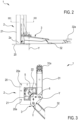
Figure 2 is a detailed lateral view of a lift according to the present invention; -
Figure 3 is a cross-sectional view, according to line III-III, of the lift offigure 2 ; -
Figures 4 and 5 are further detailed perspective views of a lift according to the present invention; -
Figure 6 is a detailed top view of a lift according to the present invention; -
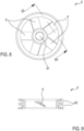
Figure 7 is a perspective view of a rotary member of the lift; -
Figure 8 is a top view of a rotary member offigure 7 ; -
Figure 9 is a cross-sectional view, according to line IX-IX, of the rotary member offigure 8 ; -
Figure 10 is a further schematic view of the lift according to the present invention. - It should be observed that in the present detailed description, corresponding parts illustrated in the various figures are indicated using the same reference numbers. The figures could illustrate the object of the invention using non-full-scale representations; thus, parts and components illustrated in the figures regarding the object of the invention could exclusively regard schematic representations.
- The expression "vertical" used relating to components of the lift, refers to a use condition thereof during which the lift carries out, or may be used for, a procedure for lifting/lowering a vehicle with respect to the ground.
- The lift described and claimed hereinafter may comprise/use at least one
control unit 50 designed to control the operating conditions provided by the lift and/or the control of the method steps for lifting a vehicle. Thecontrol unit 50 may be single unit one or it may consist of a plurality of distinct control units depending on the design choices and operative needs. The expression control unit is used to indicate an electronic component which may comprise at least one of: a digital processor (CPU), an analogue circuit, or a combination of one or more digital processors with one or more analogue circuits. The control unit may be "configured" or "programmed" to perform some steps: this may basically be obtained using any means which allows to configure or programme the control unit. For example, should the control unit comprising one or more CPUs and one or more memories, one or more programmes may be stored in appropriate memory banks connected to the CPU or to the CPUs; the programme or programmes contain instructions which, when run by the CPU or by the CPUs, programme or configure the control unit to perform the operations described relating to the control unit. Alternatively, if the control unit is or comprises an analogue circuit, then the circuit of the control unit may be designed to include a circuit configured, in use, to process electrical signals so as to perform the steps relative to the control unit. - Parts of the method described herein may be obtained by means of a data processing unit, or control unit, which may be technically replaced with one or more computers designed to run a portion of a software or firmware programme loaded on a storage medium. Such software programme may be written in any programming language of the known type. If two or more, the computers may be connected to each other through a data connection such that the computing capacity thereof is shared in any manner; therefore, the computers may even be installed in geographically different positions, creating a distributed computing environment through the aforementioned data connection.
- The data processing unit, or control unit, may be a general-purpose processor configured to run one or more parts of the process identified in the present disclosure through the software or firmware programme, or it may be an ASIC or dedicated process or an FPGA, specifically programmed to at least partly carry out operations of the method described herein.
- The storage medium may be non-transitory and it may be inside or outside the processor, or control unit, or data processing unit, and it may - specifically - be a memory geographically arranged remotely with respect to the computer. Furthermore, the storage medium may be physically split into several portions, or in form of cloud, and the software or firmware programme may physically provide for portions stored on storage portions geographically split from each other.
-
Reference number 1 indicates a vehicle lift. For example, the lift may be used in the automotive industry for servicing various types of vehicles, including cars, trucks, and agricultural vehicles. - As shown in the accompanying figures, the
lift 1 comprises at least onecolumn 2 extending, in use, along a vertical direction between abase portion 2a and atop portion 2b (see for examplefigure 1 ). Thecolumn 2 defines the vertical element for supporting the lift, configured to support the vehicle suspended with respect to the ground; thecolumn 2 may be fixed to the ground, for example using screw/bolt systems. Thecolumn 2 may comprise abase plate 20, optionally made of metal material, configured to be fixed to the ground and from which there emerges, over the entire extension of thecolumn 2, asupport frame 21, also optionally made of metal material. As shown infigure 3 , thebase plate 20 comprises a plurality ofholes 20a configured to receive a fastening screw suitable to allow the locking of theplate 20 and - as a result - the entire column to the ground. Thesupport frame 21 is joined as a single piece to thebase plate 20 and it defines - therein - a seat 22 (figure 3 ) configured to receive - engaged thereto - one or more components of thelift 1 which will be better described hereinafter. - Along the entire extension thereof, the
support frame 21 has a cross-section with constant profile, optionally having a C-shaped or substantially V-shaped profile (see for example the top view offigure 3 ). In detail, thesupport frame 21 is obtained by means of one or more sheet layers made of metal material. - As shown in
figures 4 and 5 , thecolumn 2 may further comprise, optionally at thetop portion 2b, a support plate 30: thesupport plate 30 is juxtaposed to thebase plate 20 with respect to theframe 21 and it essentially defines an end element of thecolumn 2. - The
lift 1 comprises only onecolumn 2 or it may comprise a plurality ofcolumns 2 distinct and spaced from each other.Figure 1 shows, by way of non-limiting example, alift 1 comprising two columns 2 (a first and a second column): the columns are arranged spaced from each other and they extend along a vertical direction, parallel to each other. The columns are spaced apart so as to allow to position, interposed with respect to each other, at least one vehicle. Thelift 1 comprises at least one carriage 3 (figure 1 ) slidably movable along thecolumn 2. In detail, thelift 1 comprises acarriage 3 for eachcolumn 2; thecarriage 3 defines the movable element of thelift 1 suitable to carry the vehicle in contact to move it (in particular lift it and lower it) with respect to the ground, for example so as to allow an operator to work on the vehicle. Thecarriage 3 is movable along thecolumn 2 approaching and moving away with respect to thebase portion 2a (optionally with respect to the plate 20). Thecarriage 3 comprises at least one lifting arm configured to contact a vehicle, optionally the bodywork of the vehicle, so as to allow the lifting thereof; the arm of the carriage lies substantially along a plane orthogonal to an extension direction of thecolumn 2. The arm may be of the orientable type, that is rotatably movable around an axis Y parallel to the extension direction of the column 2: such axis Y may be arranged outside thesupport frame 21 for example as shown infigure 3 . Additionally or alternatively, the arm may be of the extensible type, that is configured to vary the length thereof. - In a non-limiting way, the
carriage 3 may comprise two liftingarms 31, 32 (figure 1 ) both configured to contact a vehicle, optionally the body of the vehicle, so as to allow the lifting thereof. The liftingarms arms lift 1 shown in the attached figures has a first andsecond arm arms orientable arm 31 and asecond arm 32 which is both orientable and of the extensible type. - As shown in the accompanying figures, each arm carries - at the end - a support foot configured to directly contact the bodywork of the vehicle; in particular, the first and second arm carry - at the end -
respective feet - As specified above, the
lift 1 may comprise a first and a second column. Should thelift 1 comprise only one column, it has only onecarriage 3 as described above. By way of non-limiting example,figure 1 shows alift 1 having a first and a second column each of which comprises acarriage 3 as described above. - The lift further comprises a movement system 4 (
figures 4 and 5 ) associated with at least onecolumn 2 and configured to move thecarriage 3 along said column. In detail, the movement system 4 is configured to move eachcarriage 3 along the respective column. Detailed hereinafter is a non-limiting embodiment of the movement system 4 associated with only onecolumn 2. - The movement system 4 comprises a screw 5, of the worm screw type, extending along at least one extension section of the
column 2 and rotatably movable around an axis X, parallel to the extension direction of thecolumn 2; in detail, the axis X passes through the centre of the screw, that is it is concentric to the screw 5: basically, the screw 5 is configured to rotate on itself around an axis thereof passing through the centre of the screw. - As shown in
figure 3 , the screw 5 is housed in theseat 22 of thesupport frame 21 and it extends along the entire frame, starting from thebase portion 2a, up to thetop portion 2b. In detail, the screw 5 extends between a first and a second end: the first end of the screw 5 is arranged at thebase portion 2a of thecolumn 2 while the second end of the screw 5 is arranged at the top portion of thecolumn 2. In even greater detail, the screw 5 is hinged - at the first end - to thebase plate 20 while - at the second end - it is hinged to the support plate 30 (figures 4 and 5 ). In this manner, the screw 5 is engaged to thecolumn 2 and movable with respect to said column around the axis X. - The movement system 4 further comprises a nut screw 6 concentrically engaged to the screw 5: the nut screw is and movable along the screw, following the rotation of said screw 5 around the axis X: the nut screw 6 is engaged - on one side- to the screw 5 and - on the other side - it is integrally joined with
carriage 3 so that the nut screw 6 andcarriage 3 are movable integrally joined along the screw 5 and - as a result - along thecolumn 2. - For example, as shown in
figures 4-6 and10 , the movement system 4 further comprises at least oneelectric motor 7 kinematically connected to screw 5 so as to allow the rotation of said screw. Basically, theelectric motor 7 is used to control the rotation of the screw 5 so that the nut screw andcarriage 3 may slide along thecolumn 2. Theelectric motor 7 may have a power rating comprised between 0.5 kW and 10 kW. Theelectric motor 7 is carried by thecolumn 2 and it may be arranged, at at least one of the end portions: for example, at thebase portion 2a or thetop portion 2b. In the attached figures, theelectric motor 7 is arranged, by way of non-limiting example, at thetop portion 2b. Theelectric motor 7 may be directly constrained to thesupport plate 30, beside the screw 5. However, the possibility of arranging anelectric motor 7 at an intermediate section of thecolumn 2 cannot be ruled out. Theelectric motor 7 is arranged outside theframe 21 of thecolumn 2, below thesupport plate 30, that is so that saidelectric motor 7 is interposed between thesupport plate 30 and thebase plate 20. - As shown in
figures 4-6 and10 , the movement system 4 further comprises onerotary member 8 rotatably integrally joined with at least one of theelectric motor 7 and the screw 5. Basically, therotary member 8 may be directly carried by a drive shaft of theelectric motor 7 or directly carried by the screw 5; the attached figures show, by way of non-limiting example, alift 1 wherein therotary member 8 is directly fixed at an end portion of the screw 5 (optionally at the second end of the screw). - The
rotary member 8 kinematically connects theelectric motor 7 to the screw 5: therotary member 8 is configured to transfer a rotary motion from theelectric motor 7 to the screw 5 and, consequently, moving thecarriage 3 along thecolumn 2. Therotary member 8 may be made of plastic and/or metal material. For example, therotary member 8 may be at least partly, optionally entirely, made of at least one of the following materials: steel, aluminium, plastic, composite material or a combination of the preceding materials. - As shown in the accompanying figures, the
rotary member 8 has a plurality ofblades 9 configured to generate, during the rotation of therotary member 8, an airflow suitable to impact one or more components of the lift, for example further components of the movement system 4. For example, thanks to the plurality ofblades 9, therotary member 8 may be configured to generate, during the rotation of therotary member 8, a (cooling) airflow suitable to at least partly impact at least theelectric motor 7 and/or one or more further components of the movement system 4; for example, the movement system 4 may comprise one or more bearings suitable to support theelectric motor 7, the screw 5, the nut screw 6 the rotation of therotary member 8 allows to generate a cooling airflow suitable to impact one or more of said components so as to allow the cooling thereof. - Basically, besides acting as a member for transmitting motion between the
electric motor 7 and screw 5, therotary member 8 essentially acts as a cooling device, for example for theelectric motor 7, optionally (more generally) for one or more further components of the movement system 4. Basically, when theelectric motor 7 is driven in rotation, therotary member 8 rotates - as a result (given that it is rotatably integrally joined with at least one of theelectric motor 7 and the screw 5) - and, thanks to the plurality of blades 9 - generates an airflow which allows to dissipate the heat, e.g., generated by theelectric motor 7, during the operation thereof. - The
rotary member 8 comprises a number ofblades 9 equal to or greater than 3, optionally equal to or comprised between 3 and 10, even more optionally equal to or comprised between 3 and 7. At least oneblade 9, optionally eachblade 9, according to a cross-section, has a wing profile, for example of the concave-convex or flat-convex or laminar concave-convex type. Thanks to the wing profile, the blade/blades is/are capable of generating an airflow suitable to impact theelectric motor 7 to cool it. - In a non-limiting way, the attached figures show a movement system 4 comprising a
rotary member 8 fixed on the screw 5: adrive member 10 connected to therotary member 8 by means of adrag element 11 is fixed on thedrive shaft 7a of theelectric motor 7. Therotary member 8 essentially defines a driven member, driven in rotation by the drive member 10 (element directly driven in rotation by the electric motor 7). - The
rotary member 8 may comprise a pulley, optionally with dual-seat (see the twoseats 9 of the pulley shown infigures 7 and9 ); the pulley has acentral hub 91 configured to allow to fix the pulley to the screw 5: thecentral hub 91 and the (dual)seat 92 of the pulley are joined together as a single piece by means of a plurality ofblades 9. Thus, thedrive member 10 may comprise a pulley, optionally with dual-seat, which is suitable to cooperate with adrag element 11 comprising at least one belt (figures 4 and 5 ). - The
rotary member 8, the drivenmember 10 and thedrag element 11 define an indirect belt drive system. Obviously, using an indirect chain drive system wherein themembers rotary member 8 is configured to define an impeller fan also capable of acting as a member for transmitting motion. - The
rotary member 8 and thedrive member 10 are constrained to thesupport plate 30, in particular on the side opposite to the electric motor 7 (figures 4 and 5 ); thedrag element 11 is also arranged juxtaposed to theelectric motor 7 with respect to thesupport plate 30. The possibility of providing anelectric motor 7 on the same side as thesupport plate 30 on which also therotary member 8 and, optionally, thedrive member 10 are arranged, cannot be ruled out. - As shown in
figure 10 , thelift 1 may comprise acasing 15 engaged to thecolumn 2 and in which there is at least partly housed, theelectric motor 7, and optionally one or more components of the movement system 4 (for example one of more bearings for supporting the rotary member 8). In particular, thecasing 15 may be arranged at the top portion of thecolumn 2; thecasing 15 may therefore be used to define, cooperating with thecolumn 2, a channel configured to allow the through-flow of an airflow. In detail, the channel may comprise: - at least one
inlet 15a configured to allow the inflow of an airflow into the channel, - at least one
outlet 15b configured to allow the ejection of an airflow from the channel. - The airflow flowing through from the channel, from the
inlet 15a to theoutlet 15b, may be generated by the rotation of therotary member 8 during the operation of theelectric motor 7. The operation of theelectric motor 7 drives in rotation therotary member 8 which, thanks to theblades 9, allows to generate an airflow in the channel: any component arranged in the channel is configured to be impacted (therefore cooled) by the airflow which may be generated by therotary member 8. For example, the electric motor 7 (optionally the bearing for supporting the rotary member 8) is arranged in the channel: in this manner, theelectric motor 7, during the operation thereof, is impacted by an airflow which allows to dissipate the heat which may be generated by the electric motor to avoid unwanted overheating. - In detail, the
casing 15 may comprise atop panel 18 arranged at thetop portion 2b of thecolumn 2 from which there emerges, in the direction of thebase portion 2a of the same column, a side wall 19: thetop panel 18 andside wall 19 delimit acompartment 16 configured to house theelectric motor 7. Basically, theelectric motor 7 is entirely housed in thecompartment 16 of the casing, together with the rotary member 8 (optionally also thesupport plate 30, thedrive member 10 and thedrag element 11 are entirely arranged in the compartment 16): as observable infigure 10 , thesupport plate 30 is entirely housed in thecompartment 16 of thecasing 15, spaced from and facing thetop panel 18. - As shown in
figure 10 , thetop portion 2b of the column, together with thecasing 15, define the channel: theside wall 19 of thecasing 15 delimits a single passage opening traversed by thecolumn portion 2 and by the screw 5 of the movement system 4 (the top portion of the column is arranged in the compartment 16). The passage opening is faced toward thebase portion 2a: said passage opening, cooperating with theframe 21 of thecolumn 2, defines at least one of theinlet 15a and theoutlet 15b of the channel. Furthermore, thecasing 15 has at least one through access configured to define at least one of theinlet 15a and theoutlet 15b of the channel; the at least one through access is defined on at least one of thetop panel 18 and theside wall 19 of the casing. In the attached figures, the through access has been shown, by way of non-limiting example, only on the side wall 19 (thetop panel 18 has been schematised, by way of non-limiting example, as without through accesses); obviously, the possibility of providing a through access on at least one of theside wall 19 and thetop panel 18 cannot be ruled out. For example as shown infigure 10 , thecasing 15 may comprise a plurality of through accesses. - The accompanying figures show, in a non-limiting way, the
inlet 15a of the channel defined on the casing (optionally defined by the through accesses of the casing 15) and an outlet defined by the cooperation between thecasing 15 and theframe 21 of thecolumn 2. The arrangement of the inlet and outlet depends on the rotation direction of therotary member 8; for example: - the
inlet 15a of the channel may be defined by the through accesses of thecasing 15 while theoutlet 15b would be defined by the cooperation between thecasing 15 andframe 21 of thecolumn 2, or - the
inlet 15a of the channel may be defined by the cooperation between thecasing 15 andframe 21 of thecolumn 2 while theoutlet 15b would be defined by the through accesses of thecasing 15. - As specified above, the airflow allows to cool the
electric motor 7, arranged in the channel. Obviously, the possibility of generating an airflow configured to cool - besides the electric motor 7 - any other component arranged in the channel, such as for example a bearing for supporting therotary member 8, cannot be ruled out. Obviously, the possibility of arranging an electric motor outside thecasing 15 cannot be ruled out; the airflow which may be generated by the rotary member 8 (arranged inside the casing 15) would allow to impact only the components arranged in the channel, such as for example a bearing for supporting therotary member 8. - The
lift 1 may comprise at least one sensor 40 (figures 4-6 and10 ), for example an inductive sensor, carried by thesupport plate 30. Thesensor 40 is configured to emit a representative signal relating to therotary member 8, for example at least one of: a rotation speed of therotary member 8, an angular position of therotary member 8 with respect to an initial reference position, a number of rotations carried out by therotary member 8 with respect to an initial reference position, a rotation speed of the screw 5, angular position of the screw 5 with respect to an initial reference position, a number of rotations carried out by the screw 5 with respect to an initial reference position. Obviously, the possibility of using a different sensor associated with thecolumn 2 and emitting a representative signal directly relating to thecarriage 3, for example at least one of: a position of thecarriage 3 along thecolumn 2, a height of thecarriage 3 with respect to the plane, in use, for resting thecolumn 2, a sliding speed of thecarriage 3 along thecolumn 2, cannot be ruled out. - The
lift 1 may comprise at least onecontrol unit 50 connected to thesensor 40 and configured to receive and process the representative signal emitted by the latter and, as a function of said signal, determine a position and/or a sliding speed of thecarriage 3 along thecolumn 2. Furthermore, thecontrol unit 50 is active to control theelectric motor 7 and, as a function of the representative signal emitted by thesensor 40, it may control theelectric motor 7 to manage the position and sliding speed of the latter along thecolumn 2. - As described above, the
lift 1 may comprise a first and a second column, each according to thecolumn 2 described above that is comprising abase plate 20, asupport frame 21, optionally asupport plate 30. Should thelift 1 have a first and second column, it may comprise twoelectric motors 7, that is a first and second electric motor, each of which is carried by arespective column 2 and it is configured to move arespective carriage 3. In particular, the movement system 4 may comprise a first screw (according to the screw 5 described above) engaged to a first nut screw (according to the nut screw 6 described above): the first nut screw is engaged - on one side - to the first screw and - on the other side - to a first carriage carried by the first column. Fixed on the first screw is a first rotary member (according to therotary member 8 described above): the first rotary member is driven in rotation by a first drag element (according to thedrag element 11 described above) connected to a first drive member (according to thedrive member 10 described above) fixed on the first electric motor (according to theelectric motor 7 described above). Basically, thefirst carriage 3 is moved by the first electric motor. - Likewise, the movement system 4 may comprise a second screw (according to the screw 5 described above) engaged to a second nut screw (according to the nut screw 6 described above): the second nut screw is engaged - on one side - to the second screw and - on the other side - to a second carriage carried by the second column. Fixed on the second screw is a second rotary member (according to the
rotary member 8 described above): the second rotary member is driven in rotation by a second drag element (according to thedrag element 11 described above) connected to a second drive member (according to thedrive member 10 described above) fixed on second electric motor (according to theelectric motor 7 described above). Basically, thesecond carriage 3 is moved by the first electric motor. - Thus, each carriage may be independently moved by a respective electric motor. The
lift 1 may comprise acasing 15 for each electric motor. As described above, thecasing 15, cooperating with therespective column 2, is configured to define the channel suitable to allow the through-flow of air between theinlet 15a and theoutlet 15b, useful for cooling one or more components of the movement system 4, for example of the respective electric motor 7.Thecontrol unit 50 may be connected to both electric motors for synchronising, in a per se known manner, the movement of the carriages along the first and second column. Alternatively, thelift 1 may comprise only oneelectric motor 7 sole associated with one of the first and the second column. Thecolumn 2 carrying the electric motor is of the type described above while the first electric motor may solely comprise: the column, carrying acarriage 3, a screw 5 housed in thecolumn 2, a nut screw 6 slidably engaged to thecarriage 3 and to the screw 5. The screws 5 of the two columns are connected to each other in motion, in a per se known manner, by means of a drive system, for example a chain drive system: thus, the activation of the singleelectric motor 7 may allow the movement of the screws of the first and second column. In the latter described embodiment, thelift 1 may comprise acasing 15 for eachelectric motor 7, that is asingle casing 15 for the single electric motor. - Furthermore, forming an object of the present invention is a method of lifting vehicles using the e lift according to the description reported above and/or according to the attached claims.
- The method envisages the following steps:
- providing the at least one
carriage 3 in proximity of the ground, - arranging a vehicle above the at least one lifting arm,
- actuating the at least one
electric motor 7 of thelift 1 to move saidcarriage 3 along the column to carry the at least one arm in contact with the vehicle and lift it with respect to the ground. - During the actuation of the
electric motor 7, therotary member 8 rotates and generates an airflow suitable to impact one or more components of the movement system 4, for example at least partly theelectric motor 7 and/or a bearing for supporting therotary member 8. Should thelift 1 have thecasing 15, during the actuation of theelectric motor 7, therotary member 8 rotates to generate - inside the channel - an airflow flowing in from theinlet 15a and flowing out from theoutlet 15b suitable to impact one or more components of the movement system, for example at least partly theelectric motor 7 and/or a bearing for supporting therotary member 8. - The present invention offers significant advantages with respect to the state-of-the-art solutions. In particular,
rotary member 8 may be used for moving the screw 5 and thecorresponding carriage 3 and, at the same time, for generating a cooling airflow (for example for the electric motor 7); therotary member 8 allows to provide a reliable lift capable of operating continuously without the need for machine downtime. Basically, the possibility to move thecarriages 3 continuously significantly increases the productivity of the lift. Furthermore, it should be observed that the use of arotary member 8 capable of generating a cooling airflow (for example suitable to impact the electric motor 7) allows to provide alift 1 capable of avoiding unwanted overheating, therefore providing an extremely safe and reliable lift.
Claims (15)
- Vehicle lift (1) comprising:- at least one column (2),- at least one carriage (3) slidably movable along the column (2), said carriage (3) comprising at least one lifting arm configured to contact a vehicle to allow the lifting thereof,- a movement system (4) configured to move the carriage (3) along the column (2), the movement system (4) comprising:characterised by the fact that the rotary member (8) has a plurality of blades (9) configured to generate an airflow during the rotation of the rotary member (8) itself.o at least one rotary member (8),o at least one electric motor (7) configured to rotate said rotary member (8),
- Lift according to the preceding claim, wherein the movement system (4) comprises:- at least one screw (5) extending along an extension section of the column (2) and rotatably movable around an axis (X),- at least one nut screw (6) engaged to the screw (5) and movable, following the rotation of the screw (5), along said screw, said nut screw (6) being engaged to the carriage (3) and movable together with the latter along the screw (5),wherein the electric motor (7) is kinematically connected to the screw (5) and configured to rotate said screw, wherein the rotary member (8) is rotatably integrally joined with at least one of the electric motor (7) and the screw (5).
- Lift according to claim 2, wherein the rotary member (8) kinematically connects the electric motor (7) to the screw (5), said rotary member (8) being configured to transfer a rotary motion from the electric motor (7) to the screw (5).
- Lift according to claim 2 or 3, wherein the rotary member (8) is directly fixed to the screw (5).
- Lift according to any one of claims 2 to 4, wherein the column (2) extends between a base portion (2a) and a top portion (2b), wherein the movement system (4) is arranged at the top portion (2b) of the column (2),
wherein the screw (5) extends between a first and a second end, wherein the first end of the screw (5) is arranged at the base portion (2a) of the column (2) whereas the second end of the screw (5) is arranged at the top portion of the column (2), wherein the rotary member (8) is fixed at the second end of the screw (5). - Lift according to any one of the preceding claims, wherein the movement system (4) comprises:- at least one drive member (10) fixed to a drive shaft (7a) of the electric motor (7),- at least one drag element (11) connecting the movement of the drive member (10) with the rotation of the rotary member (8),wherein the rotary member (8) defines a driven member rotated by the drive member (10).
- Lift according to the preceding claim, wherein the rotary member (8) comprises a pulley, optionally of the dual-seat type, wherein the drive member (10) comprises a pulley, optionally of the dual-seat type, wherein the drag element (11) comprises at least one belt.
- Lift according to any one of the preceding claims comprising at least one casing (15) engaged to the column (2) inside which the rotary member (8) is at least partly housed, said casing (15) defining, cooperating with said at least one column (2), at least one channel configured to allow the through-flow of the airflow generated by the rotary member (8), said channel comprising:- at least one inlet (15a) configured to allow the inflow of an airflow into the channel,- at least one outlet (15b) configured to allow the ejection of an airflow from the channel.
- Lift according to the preceding claim, wherein the electric motor (7) is at least partly arranged in the channel which is configured to convey an airflow from the inlet (15a) to the outlet (15b) suitable to at least partly impact said electric motor (7).
- Lift according to claim 8 or 9, wherein the electric motor (7) is entirely housed in the casing and interposed between the inlet (15a) and the outlet (15b) of the channel, wherein the rotary member (8) is entirely housed in the casing (15).
- Lift according to any one of claims 8 to 10, wherein the casing (15) is arranged outside the column (2), optionally at the top portion (2b).
- Lift according to any one of the preceding claims, wherein the rotary member (8) comprises a number of blades (9) equal to or greater than 3, optionally equal to or comprised between 3 and 10, even more optionally equal to or comprised between 3 and 7.
- Lift according to any one of the preceding claims, wherein one or more of said blades (9), according to a cross-section, has a wing profile,
optionally, the profile of at least one of said blades (9), optionally of all blades (9), of the rotary member (8) is of at least one of the following types: concave-convex, or flat-convex, or laminar concave-convex. - Lift according to any one of the preceding claims, wherein the at least one column (2) comprises a first and a second column spaced apart and parallel with respect to each other, wherein the first column carries a first carriage which is slidably movable along said first column, said second column carries a second carriage which is slidably movable along said second column,wherein the movement system (4) comprises:- a first screw linked to the first column, said first screw extending along at least one extension section of the first column and being rotatably movable around an axis,- a first nut screw engaged, on one side, to the first screw and, on the other side, to the first carriage, said first nut screw being movable, following the rotation of the first screw, along said first screw together with the first carriage,- a second screw linked to the second column, said second screw extending along at least one extension section of the second column and being rotatably movable around a respective axis,- a second nut screw engaged, on one side, to the second screw and, on the other side, to the second carriage, said second nut screw being movable, following the rotation of the second screw, along said second screw together with the second carriage,wherein the at least one rotary member (8) is rotatably integrally joined with at least one of the electric motor (7), the first screw and the second screw, the at least one electric motor (7) being kinematically connected to at least one of the first and the second screw so as to allow the rotation of the latter around the respective axes.
- Method for lifting vehicles using the lift (1) according to any one of the preceding claims, wherein said methodcomprises the following steps:- providing the at least one carriage (3) in proximity of the ground on which said lift rests,- arranging a vehicle above the at least one lifting arm,- actuating the at least one electric motor (7) of the lift (1) to move said carriage (3) along the column to carry the at least one arm in contact with the bodywork and lift the vehicle with respect to the ground,wherein, when actuating the electric motor (7), the rotary member (8) rotates and generates an airflow.
Applications Claiming Priority (1)
| Application Number | Priority Date | Filing Date | Title |
|---|---|---|---|
| IT102021000021509A IT202100021509A1 (en) | 2021-08-06 | 2021-08-06 | VEHICLE LIFTER AND PROCEDURE FOR LIFTING VEHICLES |
Publications (2)
| Publication Number | Publication Date |
|---|---|
| EP4129887A1 EP4129887A1 (en) | 2023-02-08 |
| EP4129887B1 true EP4129887B1 (en) | 2024-05-01 |
Family
ID=78536497
Family Applications (1)
| Application Number | Title | Priority Date | Filing Date |
|---|---|---|---|
| EP22189136.9A Active EP4129887B1 (en) | 2021-08-06 | 2022-08-05 | Vehicle lift and method for lifting vehicles |
Country Status (4)
| Country | Link |
|---|---|
| US (1) | US20230042798A1 (en) |
| EP (1) | EP4129887B1 (en) |
| ES (1) | ES2985711T3 (en) |
| IT (1) | IT202100021509A1 (en) |
Families Citing this family (1)
| Publication number | Priority date | Publication date | Assignee | Title |
|---|---|---|---|---|
| USD1069528S1 (en) * | 2022-10-13 | 2025-04-08 | Gabriel Del Valle | Lift pad centering tool |
Family Cites Families (13)
| Publication number | Priority date | Publication date | Assignee | Title |
|---|---|---|---|---|
| DE2556691C3 (en) | 1975-12-16 | 1980-07-24 | Otto Nussbaum Kg, Fertigungstechnik Und Maschinenbau, 7640 Kehl | Conveyor device, in particular for lifting loads |
| IT1087155B (en) | 1976-12-14 | 1985-05-31 | Beissbarth Osmond | LIFT BRIDGE |
| CH635555A5 (en) | 1980-06-19 | 1983-04-15 | Julio Villars | Lifting installation, particularly elevator for vehicles |
| US5248022A (en) * | 1990-11-28 | 1993-09-28 | Tokyo Electron Limited | Driving device having sealing mechanism |
| US20040247423A1 (en) * | 2003-05-19 | 2004-12-09 | James Thiel | Multi-lift for lifting and storing motorcycles and other vehicles |
| MX2007004721A (en) * | 2004-10-19 | 2007-08-03 | Delaney Machinerie Inc | Load displacement apparatus. |
| DE102005006920B3 (en) * | 2005-02-16 | 2006-07-06 | Roland Hörnstein GmbH & Co. KG | Lifting column device for two-column lifting platforms for vehicle has drive unit, electric motor or hydraulic power unit which is arranged within lifting column profile and is attached at upper end of lifting column profile |
| CN104828739A (en) * | 2015-04-29 | 2015-08-12 | 汪涛 | Heat-radiated-through-fan apparatus for maintenance of electric power iron tower and using method thereof |
| CN105502218B (en) * | 2016-01-15 | 2018-09-11 | 孝感市大口贸易有限公司 | A kind of liftable medical carrying platform of modified |
| WO2017129849A1 (en) * | 2016-01-25 | 2017-08-03 | Kone Corporation | An elevator |
| CN212042789U (en) * | 2019-05-15 | 2020-12-01 | 米沃奇电动工具公司 | router |
| CN110182716A (en) | 2019-05-30 | 2019-08-30 | 广州高昌机电股份有限公司 | Two column lifting equipments of one kind and lift control method |
| CN112919367B (en) * | 2021-01-28 | 2023-07-04 | 扬宇光电(深圳)有限公司 | Warehouse management intelligent robot based on Internet of things |
-
2021
- 2021-08-06 IT IT102021000021509A patent/IT202100021509A1/en unknown
-
2022
- 2022-08-05 ES ES22189136T patent/ES2985711T3/en active Active
- 2022-08-05 US US17/881,908 patent/US20230042798A1/en not_active Abandoned
- 2022-08-05 EP EP22189136.9A patent/EP4129887B1/en active Active
Also Published As
| Publication number | Publication date |
|---|---|
| EP4129887A1 (en) | 2023-02-08 |
| US20230042798A1 (en) | 2023-02-09 |
| IT202100021509A1 (en) | 2023-02-06 |
| ES2985711T3 (en) | 2024-11-07 |
Similar Documents
| Publication | Publication Date | Title |
|---|---|---|
| EP4129887A1 (en) | Vehicle lift and method for lifting vehicles | |
| US7854293B2 (en) | Steering operated by linear electric device | |
| CN107954000A (en) | Include the turbojet nacelle for the returning face plate that commutates | |
| KR20140124423A (en) | Chassis dynamometer | |
| KR20210104269A (en) | Electronic Control Unit | |
| KR20090052053A (en) | Turntable devices for body assembly lines of cars | |
| CN109960390A (en) | A kind of computer equipment of heat sinking function | |
| EP3802339B1 (en) | A safety lifting device | |
| US20220097750A1 (en) | Telescope drive bracket with anti-rotation features | |
| US7352575B2 (en) | Dynamic air moving system | |
| EP0235305B1 (en) | Brake system for industrial robots | |
| JP3685879B2 (en) | Machine tool with pivotable spindle head | |
| JP6658285B2 (en) | Fatigue and durability test equipment | |
| CN215898287U (en) | Heat radiator for energy-conserving high-efficient electromechanical device | |
| CN108557693A (en) | A kind of four-column type car lift mesa structure | |
| JP3029858B2 (en) | Punch press | |
| EP3344569B1 (en) | Optical encoder and motor assembly | |
| CN111367306B (en) | Unmanned aerial vehicle positioner | |
| CN120397359A (en) | Unmanned aerial vehicle hangar and vehicle | |
| CN217655206U (en) | Device for detecting line condition in weak current integrated system | |
| CN116461090B (en) | Extrusion mechanism of 3D printer | |
| CN213137964U (en) | Anti-ejection device of friction press | |
| CN219275994U (en) | Perforating device with positioning function | |
| CN206457154U (en) | Arc elevator door-motor | |
| CN220602571U (en) | Mobile environment detection device for machine room |
Legal Events
| Date | Code | Title | Description |
|---|---|---|---|
| PUAI | Public reference made under article 153(3) epc to a published international application that has entered the european phase |
Free format text: ORIGINAL CODE: 0009012 |
|
| STAA | Information on the status of an ep patent application or granted ep patent |
Free format text: STATUS: THE APPLICATION HAS BEEN PUBLISHED |
|
| AK | Designated contracting states |
Kind code of ref document: A1 Designated state(s): AL AT BE BG CH CY CZ DE DK EE ES FI FR GB GR HR HU IE IS IT LI LT LU LV MC MK MT NL NO PL PT RO RS SE SI SK SM TR |
|
| P01 | Opt-out of the competence of the unified patent court (upc) registered |
Effective date: 20230515 |
|
| STAA | Information on the status of an ep patent application or granted ep patent |
Free format text: STATUS: REQUEST FOR EXAMINATION WAS MADE |
|
| 17P | Request for examination filed |
Effective date: 20230804 |
|
| RBV | Designated contracting states (corrected) |
Designated state(s): AL AT BE BG CH CY CZ DE DK EE ES FI FR GB GR HR HU IE IS IT LI LT LU LV MC MK MT NL NO PL PT RO RS SE SI SK SM TR |
|
| GRAP | Despatch of communication of intention to grant a patent |
Free format text: ORIGINAL CODE: EPIDOSNIGR1 |
|
| STAA | Information on the status of an ep patent application or granted ep patent |
Free format text: STATUS: GRANT OF PATENT IS INTENDED |
|
| INTG | Intention to grant announced |
Effective date: 20231130 |
|
| RAP1 | Party data changed (applicant data changed or rights of an application transferred) |
Owner name: VEHICLE SERVICE GROUP ITALY S.R.L. |
|
| GRAS | Grant fee paid |
Free format text: ORIGINAL CODE: EPIDOSNIGR3 |
|
| GRAA | (expected) grant |
Free format text: ORIGINAL CODE: 0009210 |
|
| STAA | Information on the status of an ep patent application or granted ep patent |
Free format text: STATUS: THE PATENT HAS BEEN GRANTED |
|
| AK | Designated contracting states |
Kind code of ref document: B1 Designated state(s): AL AT BE BG CH CY CZ DE DK EE ES FI FR GB GR HR HU IE IS IT LI LT LU LV MC MK MT NL NO PL PT RO RS SE SI SK SM TR |
|
| REG | Reference to a national code |
Ref country code: GB Ref legal event code: FG4D |
|
| REG | Reference to a national code |
Ref country code: CH Ref legal event code: EP |
|
| REG | Reference to a national code |
Ref country code: IE Ref legal event code: FG4D |
|
| REG | Reference to a national code |
Ref country code: DE Ref legal event code: R096 Ref document number: 602022003192 Country of ref document: DE |
|
| REG | Reference to a national code |
Ref country code: LT Ref legal event code: MG9D |
|
| REG | Reference to a national code |
Ref country code: NL Ref legal event code: MP Effective date: 20240501 |
|
| PG25 | Lapsed in a contracting state [announced via postgrant information from national office to epo] |
Ref country code: IS Free format text: LAPSE BECAUSE OF FAILURE TO SUBMIT A TRANSLATION OF THE DESCRIPTION OR TO PAY THE FEE WITHIN THE PRESCRIBED TIME-LIMIT Effective date: 20240901 |
|
| PG25 | Lapsed in a contracting state [announced via postgrant information from national office to epo] |
Ref country code: BG Free format text: LAPSE BECAUSE OF FAILURE TO SUBMIT A TRANSLATION OF THE DESCRIPTION OR TO PAY THE FEE WITHIN THE PRESCRIBED TIME-LIMIT Effective date: 20240501 |
|
| PG25 | Lapsed in a contracting state [announced via postgrant information from national office to epo] |
Ref country code: FI Free format text: LAPSE BECAUSE OF FAILURE TO SUBMIT A TRANSLATION OF THE DESCRIPTION OR TO PAY THE FEE WITHIN THE PRESCRIBED TIME-LIMIT Effective date: 20240501 Ref country code: HR Free format text: LAPSE BECAUSE OF FAILURE TO SUBMIT A TRANSLATION OF THE DESCRIPTION OR TO PAY THE FEE WITHIN THE PRESCRIBED TIME-LIMIT Effective date: 20240501 |
|
| PG25 | Lapsed in a contracting state [announced via postgrant information from national office to epo] |
Ref country code: GR Free format text: LAPSE BECAUSE OF FAILURE TO SUBMIT A TRANSLATION OF THE DESCRIPTION OR TO PAY THE FEE WITHIN THE PRESCRIBED TIME-LIMIT Effective date: 20240802 |
|
| PG25 | Lapsed in a contracting state [announced via postgrant information from national office to epo] |
Ref country code: PT Free format text: LAPSE BECAUSE OF FAILURE TO SUBMIT A TRANSLATION OF THE DESCRIPTION OR TO PAY THE FEE WITHIN THE PRESCRIBED TIME-LIMIT Effective date: 20240902 |
|
| REG | Reference to a national code |
Ref country code: AT Ref legal event code: MK05 Ref document number: 1682139 Country of ref document: AT Kind code of ref document: T Effective date: 20240501 |
|
| PG25 | Lapsed in a contracting state [announced via postgrant information from national office to epo] |
Ref country code: NL Free format text: LAPSE BECAUSE OF FAILURE TO SUBMIT A TRANSLATION OF THE DESCRIPTION OR TO PAY THE FEE WITHIN THE PRESCRIBED TIME-LIMIT Effective date: 20240501 |
|
| PG25 | Lapsed in a contracting state [announced via postgrant information from national office to epo] |
Ref country code: AT Free format text: LAPSE BECAUSE OF FAILURE TO SUBMIT A TRANSLATION OF THE DESCRIPTION OR TO PAY THE FEE WITHIN THE PRESCRIBED TIME-LIMIT Effective date: 20240501 |
|
| PG25 | Lapsed in a contracting state [announced via postgrant information from national office to epo] |
Ref country code: PL Free format text: LAPSE BECAUSE OF FAILURE TO SUBMIT A TRANSLATION OF THE DESCRIPTION OR TO PAY THE FEE WITHIN THE PRESCRIBED TIME-LIMIT Effective date: 20240501 |
|
| PG25 | Lapsed in a contracting state [announced via postgrant information from national office to epo] |
Ref country code: LV Free format text: LAPSE BECAUSE OF FAILURE TO SUBMIT A TRANSLATION OF THE DESCRIPTION OR TO PAY THE FEE WITHIN THE PRESCRIBED TIME-LIMIT Effective date: 20240501 |
|
| PG25 | Lapsed in a contracting state [announced via postgrant information from national office to epo] |
Ref country code: PT Free format text: LAPSE BECAUSE OF FAILURE TO SUBMIT A TRANSLATION OF THE DESCRIPTION OR TO PAY THE FEE WITHIN THE PRESCRIBED TIME-LIMIT Effective date: 20240902 Ref country code: PL Free format text: LAPSE BECAUSE OF FAILURE TO SUBMIT A TRANSLATION OF THE DESCRIPTION OR TO PAY THE FEE WITHIN THE PRESCRIBED TIME-LIMIT Effective date: 20240501 Ref country code: NO Free format text: LAPSE BECAUSE OF FAILURE TO SUBMIT A TRANSLATION OF THE DESCRIPTION OR TO PAY THE FEE WITHIN THE PRESCRIBED TIME-LIMIT Effective date: 20240801 Ref country code: NL Free format text: LAPSE BECAUSE OF FAILURE TO SUBMIT A TRANSLATION OF THE DESCRIPTION OR TO PAY THE FEE WITHIN THE PRESCRIBED TIME-LIMIT Effective date: 20240501 Ref country code: LV Free format text: LAPSE BECAUSE OF FAILURE TO SUBMIT A TRANSLATION OF THE DESCRIPTION OR TO PAY THE FEE WITHIN THE PRESCRIBED TIME-LIMIT Effective date: 20240501 Ref country code: IS Free format text: LAPSE BECAUSE OF FAILURE TO SUBMIT A TRANSLATION OF THE DESCRIPTION OR TO PAY THE FEE WITHIN THE PRESCRIBED TIME-LIMIT Effective date: 20240901 Ref country code: HR Free format text: LAPSE BECAUSE OF FAILURE TO SUBMIT A TRANSLATION OF THE DESCRIPTION OR TO PAY THE FEE WITHIN THE PRESCRIBED TIME-LIMIT Effective date: 20240501 Ref country code: GR Free format text: LAPSE BECAUSE OF FAILURE TO SUBMIT A TRANSLATION OF THE DESCRIPTION OR TO PAY THE FEE WITHIN THE PRESCRIBED TIME-LIMIT Effective date: 20240802 Ref country code: FI Free format text: LAPSE BECAUSE OF FAILURE TO SUBMIT A TRANSLATION OF THE DESCRIPTION OR TO PAY THE FEE WITHIN THE PRESCRIBED TIME-LIMIT Effective date: 20240501 Ref country code: BG Free format text: LAPSE BECAUSE OF FAILURE TO SUBMIT A TRANSLATION OF THE DESCRIPTION OR TO PAY THE FEE WITHIN THE PRESCRIBED TIME-LIMIT Effective date: 20240501 Ref country code: AT Free format text: LAPSE BECAUSE OF FAILURE TO SUBMIT A TRANSLATION OF THE DESCRIPTION OR TO PAY THE FEE WITHIN THE PRESCRIBED TIME-LIMIT Effective date: 20240501 Ref country code: RS Free format text: LAPSE BECAUSE OF FAILURE TO SUBMIT A TRANSLATION OF THE DESCRIPTION OR TO PAY THE FEE WITHIN THE PRESCRIBED TIME-LIMIT Effective date: 20240801 |
|
| REG | Reference to a national code |
Ref country code: ES Ref legal event code: FG2A Ref document number: 2985711 Country of ref document: ES Kind code of ref document: T3 Effective date: 20241107 |
|
| PG25 | Lapsed in a contracting state [announced via postgrant information from national office to epo] |
Ref country code: DK Free format text: LAPSE BECAUSE OF FAILURE TO SUBMIT A TRANSLATION OF THE DESCRIPTION OR TO PAY THE FEE WITHIN THE PRESCRIBED TIME-LIMIT Effective date: 20240501 |
|
| PG25 | Lapsed in a contracting state [announced via postgrant information from national office to epo] |
Ref country code: EE Free format text: LAPSE BECAUSE OF FAILURE TO SUBMIT A TRANSLATION OF THE DESCRIPTION OR TO PAY THE FEE WITHIN THE PRESCRIBED TIME-LIMIT Effective date: 20240501 |
|
| PG25 | Lapsed in a contracting state [announced via postgrant information from national office to epo] |
Ref country code: CZ Free format text: LAPSE BECAUSE OF FAILURE TO SUBMIT A TRANSLATION OF THE DESCRIPTION OR TO PAY THE FEE WITHIN THE PRESCRIBED TIME-LIMIT Effective date: 20240501 |
|
| PG25 | Lapsed in a contracting state [announced via postgrant information from national office to epo] |
Ref country code: RO Free format text: LAPSE BECAUSE OF FAILURE TO SUBMIT A TRANSLATION OF THE DESCRIPTION OR TO PAY THE FEE WITHIN THE PRESCRIBED TIME-LIMIT Effective date: 20240501 Ref country code: SK Free format text: LAPSE BECAUSE OF FAILURE TO SUBMIT A TRANSLATION OF THE DESCRIPTION OR TO PAY THE FEE WITHIN THE PRESCRIBED TIME-LIMIT Effective date: 20240501 |
|
| PG25 | Lapsed in a contracting state [announced via postgrant information from national office to epo] |
Ref country code: SM Free format text: LAPSE BECAUSE OF FAILURE TO SUBMIT A TRANSLATION OF THE DESCRIPTION OR TO PAY THE FEE WITHIN THE PRESCRIBED TIME-LIMIT Effective date: 20240501 |
|
| PG25 | Lapsed in a contracting state [announced via postgrant information from national office to epo] |
Ref country code: SM Free format text: LAPSE BECAUSE OF FAILURE TO SUBMIT A TRANSLATION OF THE DESCRIPTION OR TO PAY THE FEE WITHIN THE PRESCRIBED TIME-LIMIT Effective date: 20240501 Ref country code: SK Free format text: LAPSE BECAUSE OF FAILURE TO SUBMIT A TRANSLATION OF THE DESCRIPTION OR TO PAY THE FEE WITHIN THE PRESCRIBED TIME-LIMIT Effective date: 20240501 Ref country code: RO Free format text: LAPSE BECAUSE OF FAILURE TO SUBMIT A TRANSLATION OF THE DESCRIPTION OR TO PAY THE FEE WITHIN THE PRESCRIBED TIME-LIMIT Effective date: 20240501 Ref country code: EE Free format text: LAPSE BECAUSE OF FAILURE TO SUBMIT A TRANSLATION OF THE DESCRIPTION OR TO PAY THE FEE WITHIN THE PRESCRIBED TIME-LIMIT Effective date: 20240501 Ref country code: DK Free format text: LAPSE BECAUSE OF FAILURE TO SUBMIT A TRANSLATION OF THE DESCRIPTION OR TO PAY THE FEE WITHIN THE PRESCRIBED TIME-LIMIT Effective date: 20240501 Ref country code: CZ Free format text: LAPSE BECAUSE OF FAILURE TO SUBMIT A TRANSLATION OF THE DESCRIPTION OR TO PAY THE FEE WITHIN THE PRESCRIBED TIME-LIMIT Effective date: 20240501 |
|
| REG | Reference to a national code |
Ref country code: DE Ref legal event code: R097 Ref document number: 602022003192 Country of ref document: DE |
|
| PLBE | No opposition filed within time limit |
Free format text: ORIGINAL CODE: 0009261 |
|
| STAA | Information on the status of an ep patent application or granted ep patent |
Free format text: STATUS: NO OPPOSITION FILED WITHIN TIME LIMIT |
|
| 26N | No opposition filed |
Effective date: 20250204 |
|
| PG25 | Lapsed in a contracting state [announced via postgrant information from national office to epo] |
Ref country code: LU Free format text: LAPSE BECAUSE OF NON-PAYMENT OF DUE FEES Effective date: 20240805 |
|
| PG25 | Lapsed in a contracting state [announced via postgrant information from national office to epo] |
Ref country code: MC Free format text: LAPSE BECAUSE OF FAILURE TO SUBMIT A TRANSLATION OF THE DESCRIPTION OR TO PAY THE FEE WITHIN THE PRESCRIBED TIME-LIMIT Effective date: 20240501 Ref country code: SI Free format text: LAPSE BECAUSE OF FAILURE TO SUBMIT A TRANSLATION OF THE DESCRIPTION OR TO PAY THE FEE WITHIN THE PRESCRIBED TIME-LIMIT Effective date: 20240501 |
|
| REG | Reference to a national code |
Ref country code: BE Ref legal event code: MM Effective date: 20240831 |
|
| PG25 | Lapsed in a contracting state [announced via postgrant information from national office to epo] |
Ref country code: BE Free format text: LAPSE BECAUSE OF NON-PAYMENT OF DUE FEES Effective date: 20240831 |
|
| PG25 | Lapsed in a contracting state [announced via postgrant information from national office to epo] |
Ref country code: IE Free format text: LAPSE BECAUSE OF NON-PAYMENT OF DUE FEES Effective date: 20240805 |
|
| PG25 | Lapsed in a contracting state [announced via postgrant information from national office to epo] |
Ref country code: SE Free format text: LAPSE BECAUSE OF FAILURE TO SUBMIT A TRANSLATION OF THE DESCRIPTION OR TO PAY THE FEE WITHIN THE PRESCRIBED TIME-LIMIT Effective date: 20240501 |
|
| PGFP | Annual fee paid to national office [announced via postgrant information from national office to epo] |
Ref country code: ES Payment date: 20250916 Year of fee payment: 4 |
|
| PGFP | Annual fee paid to national office [announced via postgrant information from national office to epo] |
Ref country code: DE Payment date: 20250827 Year of fee payment: 4 |
|
| PGFP | Annual fee paid to national office [announced via postgrant information from national office to epo] |
Ref country code: IT Payment date: 20250901 Year of fee payment: 4 |
|
| PGFP | Annual fee paid to national office [announced via postgrant information from national office to epo] |
Ref country code: FR Payment date: 20250825 Year of fee payment: 4 |
|
| PG25 | Lapsed in a contracting state [announced via postgrant information from national office to epo] |
Ref country code: CY Free format text: LAPSE BECAUSE OF FAILURE TO SUBMIT A TRANSLATION OF THE DESCRIPTION OR TO PAY THE FEE WITHIN THE PRESCRIBED TIME-LIMIT; INVALID AB INITIO Effective date: 20220805 |
|
| PG25 | Lapsed in a contracting state [announced via postgrant information from national office to epo] |
Ref country code: HU Free format text: LAPSE BECAUSE OF FAILURE TO SUBMIT A TRANSLATION OF THE DESCRIPTION OR TO PAY THE FEE WITHIN THE PRESCRIBED TIME-LIMIT; INVALID AB INITIO Effective date: 20220805 |
|
| REG | Reference to a national code |
Ref country code: CH Ref legal event code: H13 Free format text: ST27 STATUS EVENT CODE: U-0-0-H10-H13 (AS PROVIDED BY THE NATIONAL OFFICE) Effective date: 20260324 |
|
| PG25 | Lapsed in a contracting state [announced via postgrant information from national office to epo] |
Ref country code: CH Free format text: LAPSE BECAUSE OF NON-PAYMENT OF DUE FEES Effective date: 20250831 |