CN219275994U - Perforating device with positioning function - Google Patents
Perforating device with positioning function Download PDFInfo
- Publication number
- CN219275994U CN219275994U CN202320234518.6U CN202320234518U CN219275994U CN 219275994 U CN219275994 U CN 219275994U CN 202320234518 U CN202320234518 U CN 202320234518U CN 219275994 U CN219275994 U CN 219275994U
- Authority
- CN
- China
- Prior art keywords
- driving motor
- fixedly connected
- positioning function
- fixing frame
- screw rod
- Prior art date
- Legal status (The legal status is an assumption and is not a legal conclusion. Google has not performed a legal analysis and makes no representation as to the accuracy of the status listed.)
- Active
Links
- 230000005540 biological transmission Effects 0.000 claims description 20
- 238000004080 punching Methods 0.000 claims description 13
- 238000005096 rolling process Methods 0.000 claims description 6
- 238000005034 decoration Methods 0.000 description 2
- 238000010586 diagram Methods 0.000 description 2
- 238000005553 drilling Methods 0.000 description 2
- 238000005516 engineering process Methods 0.000 description 2
- 238000009434 installation Methods 0.000 description 2
- 238000012986 modification Methods 0.000 description 2
- 230000004048 modification Effects 0.000 description 2
- 230000007547 defect Effects 0.000 description 1
- 239000002304 perfume Substances 0.000 description 1
Images


Landscapes
- Vehicle Interior And Exterior Ornaments, Soundproofing, And Insulation (AREA)
Abstract
The embodiment of the utility model provides a perforating device with a positioning function, which relates to the technical field of automobile plate processing and comprises a base, wherein a fixing frame is fixedly connected to one side of the upper part of the base, a first driving assembly is arranged in the fixing frame, a first screw rod is rotatably connected to one side of the fixing frame, a second driving assembly is arranged in a motor base, and a perforating machine is fixedly connected to the bottom of a third driving assembly. According to the perforating device with the positioning function, provided by the embodiment of the utility model, an operator drives the first driving motor to enable the movable pressing plate to be close to the fixing frame, after the automotive interior part is fixed, the second driving motor is driven to adjust the position of the supporting frame, the third driving motor is driven to drive the movable block to move, the movable block is driven to move to drive the perforating machine to move, after the position of the perforating machine is confirmed, the position of the automotive interior part can be perforated, the automotive interior part can be stably fixed, and the perforating can be performed in multiple directions and multiple points.
Description
Technical Field
The utility model relates to the technical field of automobile plate processing, in particular to a punching device with a positioning function.
Background
The automobile interior trim mainly refers to automobile products used for refitting the inside of an automobile, and relates to aspects of the inside of the automobile, such as automobile steering wheel sleeves, automobile cushions, automobile foot pads, automobile perfumes, automobile pendants, internal ornaments, storage boxes and the like, which are automobile interior trim products.
Chinese patent publication No. (CN 215702263U), discloses "a vehicle interior trim panel perforating device with locate function, including operation panel, frame, puncher, locating plate and baffle, frame fixed mounting is on the top of operation panel, puncher slidable sets up in the bottom of frame, two the locating plate is all through locating component and operation panel swing joint, the baffle passes through moving component and two locating plate swing joint. This automotive interior plaque perforating device with locate function relates to car panel processing technology field, has solved the drilling equipment that car decoration panel used inconvenient to panel location when punching, leads to there being certain error when punching, influences the problem of later stage panel installation. "
However, this perforating device with locate function is equipped with "operation panel, frame, puncher, locating plate, slip case, motor, baffle scheduling" structure, and the structure is simple relatively, when punching to the automobile interior trim board location, must remove two locating plates to the center simultaneously and just can fix a position the automobile interior trim board, and because the influence of baffle has received, can't fix a position the interior trim board that the size is little between two locating plates, therefore has certain not enoughly.
Disclosure of Invention
The utility model provides a perforating device with a positioning function, which comprises:
the base, upper portion one side fixedly connected with mount of base, be provided with first drive assembly in the mount, one side of mount rotates and is connected with first lead screw, the one end of first lead screw with first drive assembly transmission is connected, the other end transmission of first lead screw is connected with the removal clamp plate, the one end of base is provided with the motor cabinet, set up second drive assembly in the motor cabinet, the rolling disc is installed in the rotation of second drive assembly top, the upper portion fixedly connected with support frame of rolling disc, be provided with third drive assembly on the support frame, third drive assembly bottom fixedly connected with puncher.
In a specific embodiment, an inner cavity is formed in the fixing frame, an access panel is arranged on the upper portion of the fixing frame, a baffle is fixedly connected to the side wall of the fixing frame, and the other end of the baffle penetrates through the movable pressing plate.
In a specific embodiment, the first driving assembly comprises a first driving motor and a transmission rod, the first driving motor is fixedly installed in one end of the fixing frame, one end of the transmission rod is fixedly connected with one end of an output shaft of the first driving motor, the other end of the transmission rod is rotatably connected with the other end of the fixing frame, a first bevel gear is fixedly installed on the transmission rod, and the transmission rod is arranged in the inner cavity.
In a specific embodiment, one end of the first screw rod penetrates through the fixing frame and extends into the inner cavity, one end of the first screw rod is fixedly connected with a second bevel gear, the second bevel gear is meshed with the first bevel gear, and the other end of the first screw rod penetrates through the movable pressing plate and is in threaded connection with the movable pressing plate.
In a specific embodiment, the first screw rod is located at one end of the movable pressing plate and is fixedly connected with a fixed block.
In a specific embodiment, the second driving assembly comprises a second driving motor, the second driving motor is fixedly installed in the motor base, and the top of an output shaft of the second driving motor is fixedly connected with the bottom of the rotating disc.
In a specific embodiment, the bottom of the front end of the supporting frame is provided with a groove.
In specific embodiments, the third drive assembly includes third driving motor, second lead screw and movable block, third driving motor with the one end fixed connection of support frame, third driving motor's output shaft run through in the one end of recess and extend forward, the one end of second lead screw with the one end fixed connection of third driving motor output shaft, the other end of second lead screw with the other end of recess rotates to be connected, the movable block screw thread mounting is in the second lead screw outside, the lateral wall fixedly connected with spacing slider of movable block, the bottom of movable block with the top fixed connection of puncher.
In a specific embodiment, a limiting chute for sliding the limiting slide block is formed in the side wall of the groove.
In a specific embodiment, the bottom of the base is fixedly provided with a self-locking universal wheel.
According to the perforating device with the positioning function, an operator places an automotive interior part between two baffle plates, drives the first driving motor to enable the movable pressing plate to be close to the fixing frame slowly, further fixes the automotive interior part, can drive the second driving motor to adjust the position of the supporting frame after the automotive interior part is fixed, then drives the third driving motor to drive the movable block to move after the position of the supporting frame is determined, and can punch the position of the automotive interior part after the position of the perforating machine is confirmed, so that the automotive interior part can be fixed stably, holes can be punched in multiple directions and multiple points, and the punching precision is improved.
Drawings
In order to more clearly illustrate the technical solutions of the embodiments of the present utility model, the drawings that are needed in the embodiments will be briefly described below, it being understood that the following drawings only illustrate some examples of the present utility model and therefore should not be considered as limiting the scope, and other related drawings may be obtained according to these drawings without inventive effort for a person skilled in the art.
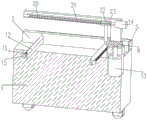
Fig. 1 is a schematic structural diagram of a base according to an embodiment of the present utility model.
Fig. 2 is a schematic structural diagram of a base according to an embodiment of the present utility model.
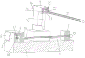
Fig. 3 is a schematic view illustrating a cross-sectional structure of a base according to an embodiment of the present utility model.
Fig. 4 is a schematic cross-sectional view of another view of a base according to an embodiment of the utility model.
Fig. 5 is a schematic cross-sectional view of another view of a base according to an embodiment of the utility model.
Icon: 1. a base; 2. self-locking universal wheels; 3. a fixing frame; 4. an access panel; 5. a first driving motor; 6. a motor base; 7. a movable pressing plate; 8. a rotating disc; 9. a support frame; 10. a puncher; 11. a first screw rod; 12. a baffle; 13. a second driving motor; 14. a third driving motor; 15. a fixed block; 16. an inner cavity; 17. a transmission rod; 18. a first bevel gear; 19. a second bevel gear; 20. a groove; 21. a second screw rod; 22. a moving block; 23. a limit sliding block; 24. limiting sliding groove.
Detailed Description
Chinese patent publication No. (CN 215702263U), discloses "a vehicle interior trim panel perforating device with locate function, including operation panel, frame, puncher, locating plate and baffle, frame fixed mounting is on the top of operation panel, puncher slidable sets up in the bottom of frame, two the locating plate is all through locating component and operation panel swing joint, the baffle passes through moving component and two locating plate swing joint. This automotive interior plaque perforating device with locate function relates to car panel processing technology field, has solved the drilling equipment that car decoration panel used inconvenient to panel location when punching, leads to there being certain error when punching, influences the problem of later stage panel installation. "
However, this have locate function perforating device is equipped with "operation panel, frame, puncher, locating plate, slip case, motor, baffle scheduling" structure, and the structure is simple relatively, when punching to the automobile interior trim board location, must remove two locating plates to the center simultaneously and just can fix a position the automobile interior trim board, and because the influence of baffle has been received, can't fix a position the interior trim board that the size is little between two locating plates, therefore has certain not enough condition to solve above-mentioned defect.
Some embodiments of the present utility model are described in detail below with reference to the accompanying drawings. The following embodiments and features of the embodiments may be combined with each other without conflict.
Referring to fig. 1 to 5, an embodiment of the present utility model provides a punching device with a positioning function, including:
Referring to fig. 2-3, an inner cavity 16 is formed in the fixing frame 3, an access board 4 is arranged on the upper portion of the fixing frame 3, equipment inside is convenient to maintain, a baffle 12 is fixedly connected to the side wall of the fixing frame 3, the other end of the baffle 12 penetrates through the movable pressing plate 7, when the movable pressing plate 7 moves towards the fixing frame 3, the baffle 12 plays a limiting role on the movable pressing plate 7, as shown in fig. 2, one end of the baffle 12 penetrates through the movable pressing plate 7, one end of the baffle 12 can slide in a rectangular hole of the movable pressing plate 7, and the baffle 12 can avoid damage to an automotive interior part when the first screw rod 11 rotates.
Referring to fig. 1-5, the first driving assembly includes a first driving motor 5 and a driving rod 17, the first driving motor 5 is fixedly installed in one end of the fixing frame 3, one end of the driving rod 17 is fixedly connected with one end of an output shaft of the first driving motor 5, the other end of the driving rod 17 is rotationally connected with the other end of the fixing frame 3, a first bevel gear 18 is fixedly installed on the driving rod 17, the driving rod 17 is disposed in the inner cavity 16, the driving rod 17 can be driven to rotate by rotation of the first driving motor 5, the driving rod 17 can be driven to rotate by rotation of the first bevel gear 18, the first bevel gear 18 is meshed with the second bevel gear 19 to drive the first screw 11 to rotate, and the first screw 11 can drive the movable pressing plate 7 to move forwards and backwards (the other end of the first screw 11 is in threaded connection with the movable pressing plate 7).
Further, the first screw rod 11 is located at one end of the movable pressing plate 7 and is fixedly connected with the fixed block 15, so that the movable pressing plate 7 is prevented from being separated from the constraint of the first screw rod 11.
Referring to fig. 4, the second driving assembly includes a second driving motor 13, the second driving motor 13 is fixedly installed in the motor base 6, the top of an output shaft of the second driving motor 13 is fixedly connected with the bottom of the rotating disc 8, and the second driving motor 13 can drive the rotating disc 8 to rotate left and right.
Referring to fig. 3-4, a groove 20 is formed at the bottom of the front end of the supporting frame 9.
Further, the third drive assembly includes third driving motor 14, second lead screw 21 and movable block 22, third driving motor 14 and the one end fixed connection of support frame 9, the output shaft of third driving motor 14 runs through in the one end of recess 20 and extends forward, the one end of second lead screw 21 and the one end fixed connection of third driving motor 14 output shaft, the other end of second lead screw 21 and the other end rotation of recess 20 are connected, movable block 22 screw thread mount is in the second lead screw 21 outside, the lateral wall fixedly connected with spacing slider 23 of movable block 22, third driving motor 14 can drive second lead screw 21 and rotate, the movable block 22 forward movement can be driven to the second lead screw 21 pivoted simultaneously, movable block 22 forward movement can drive puncher 10 to remove (the bottom of movable block 22 and the top fixed connection of puncher 10).
Further, the side wall of the groove 20 is provided with a limiting chute 24 for sliding of the limiting slide block 23, so that the moving direction of the moving block 22 is limited, and the condition that the moving block 22 shakes left and right is avoided.
Notice that: the first driving motor 5, the second driving motor 13 and the third driving motor 14 all need to adopt forward and reverse rotation motors, so that the transmission connection of all the components is facilitated.
Referring to fig. 1, a self-locking universal wheel 2 is fixedly installed at the bottom of a base 1, so that the base 1 can be conveniently moved and locked at a designated position.
In summary, according to the perforating device with the positioning function, an operator places an automotive interior part between two baffles 12, then drives the first driving motor 5 to enable the moving pressing plate 7 to slowly approach the fixing frame 3, and further fixes the automotive interior part (the rotation of the first driving motor 5 can drive the transmission rod 17 to rotate, the rotation of the transmission rod 17 can drive the first bevel gear 18 to rotate, the first bevel gear 18 is meshed with the second bevel gear 19 to drive the first screw rod 11 to rotate, the rotation of the first screw rod 11 can drive the moving pressing plate 7 to move forwards and backwards), after the automotive interior part is fixed, the second driving motor 13 can be driven to adjust the position of the supporting frame 9 (namely, the forward or backward inclination angle of the supporting frame 9), then after the position of the supporting frame 9 is determined, the third driving motor 14 is driven to drive the moving block 22 to move, the moving block 22 drives the machine 10 to move (the rotation of the third driving motor 14 can drive the second screw rod 21 to rotate in the groove 20), the second screw rod 21 can drive the moving block 22 to move forwards, and the moving block 22 can drive the moving block 22 to move forwards, and the moving block 22 can drive the machine 10 to move forwards, and the position of the automotive interior part can be punched by a plurality of perforating points can be stably punched, and the position of the automotive interior part can be punched, and the perforating device can be punched and the position of the perforating device can be punched stably and punched and the position of the automotive interior part can be punched and punched.
The above is only a preferred embodiment of the present utility model, and is not intended to limit the present utility model, but various modifications and variations can be made to the present utility model by those skilled in the art. Any modification, equivalent replacement, improvement, etc. made within the spirit and principle of the present utility model should be included in the protection scope of the present utility model.
Claims (10)
1. A perforating device with positioning function, characterized by comprising:
base (1), upper portion one side fixedly connected with mount (3) of base (1), be provided with first drive assembly in mount (3), one side rotation of mount (3) is connected with first lead screw (11), the one end of first lead screw (11) with first drive assembly transmission is connected, the other end transmission of first lead screw (11) is connected with movable clamp plate (7), the one end of base (1) is provided with motor cabinet (6), set up second drive assembly in motor cabinet (6), second drive assembly top rotates installs rolling disc (8), upper portion fixedly connected with support frame (9) of rolling disc (8), be provided with third drive assembly on support frame (9), third drive assembly bottom fixedly connected with puncher (10).
2. The perforating device with the positioning function according to claim 1, wherein an inner cavity (16) is formed in the fixing frame (3), an access board (4) is arranged on the upper portion of the fixing frame (3), a baffle plate (12) is fixedly connected to the side wall of the fixing frame (3), and the other end of the baffle plate (12) penetrates through the movable pressing plate (7).
3. The punching device with the positioning function according to claim 2, characterized in that the first driving assembly comprises a first driving motor (5) and a transmission rod (17), the first driving motor (5) is fixedly installed in one end of the fixing frame (3), one end of the transmission rod (17) is fixedly connected with one end of an output shaft of the first driving motor (5), the other end of the transmission rod (17) is rotatably connected with the other end of the fixing frame (3), a first conical gear (18) is fixedly installed on the transmission rod (17), and the transmission rod (17) is arranged in the inner cavity (16).
4. A perforating device with a positioning function according to claim 3, characterized in that one end of the first screw rod (11) penetrates through the fixing frame (3) and extends into the inner cavity (16), one end of the first screw rod (11) is fixedly connected with a second conical gear (19), the second conical gear (19) is meshed with the first conical gear (18), and the other end of the first screw rod (11) penetrates through the movable pressing plate (7) and is in threaded connection with the movable pressing plate (7).
5. The punching device with the positioning function according to claim 4, wherein the first screw rod (11) is fixedly connected with a fixed block (15) at one end of the movable pressing plate (7).
6. The perforating device with the positioning function according to claim 1, wherein the second driving assembly comprises a second driving motor (13), the second driving motor (13) is fixedly arranged in the motor base (6), and the top of an output shaft of the second driving motor (13) is fixedly connected with the bottom of the rotating disc (8).
7. The perforating apparatus with positioning function as claimed in claim 6, characterized in that the bottom of the front end of the supporting frame (9) is provided with a groove (20).
8. The punching device with the positioning function according to claim 7, characterized in that the third driving assembly comprises a third driving motor (14), a second screw rod (21) and a moving block (22), the third driving motor (14) is fixedly connected with one end of the supporting frame (9), an output shaft of the third driving motor (14) penetrates through one end of the groove (20) and extends forwards, one end of the second screw rod (21) is fixedly connected with one end of the output shaft of the third driving motor (14), the other end of the second screw rod (21) is rotatably connected with the other end of the groove (20), the moving block (22) is mounted on the outer side of the second screw rod (21) in a threaded mode, a limit sliding block (23) is fixedly connected with the side wall of the moving block (22), and the bottom of the moving block (22) is fixedly connected with the top of the punching machine (10).
9. The perforating apparatus with positioning function as claimed in claim 8, wherein the side wall of the recess (20) is provided with a limiting chute (24) for the sliding of the limiting slider (23).
10. The perforating device with the positioning function according to claim 1 is characterized in that a self-locking universal wheel (2) is fixedly arranged at the bottom of the base (1).
Priority Applications (1)
| Application Number | Priority Date | Filing Date | Title |
|---|---|---|---|
| CN202320234518.6U CN219275994U (en) | 2023-02-16 | 2023-02-16 | Perforating device with positioning function |
Applications Claiming Priority (1)
| Application Number | Priority Date | Filing Date | Title |
|---|---|---|---|
| CN202320234518.6U CN219275994U (en) | 2023-02-16 | 2023-02-16 | Perforating device with positioning function |
Publications (1)
| Publication Number | Publication Date |
|---|---|
| CN219275994U true CN219275994U (en) | 2023-06-30 |
Family
ID=86919685
Family Applications (1)
| Application Number | Title | Priority Date | Filing Date |
|---|---|---|---|
| CN202320234518.6U Active CN219275994U (en) | 2023-02-16 | 2023-02-16 | Perforating device with positioning function |
Country Status (1)
| Country | Link |
|---|---|
| CN (1) | CN219275994U (en) |
-
2023
- 2023-02-16 CN CN202320234518.6U patent/CN219275994U/en active Active
Similar Documents
| Publication | Publication Date | Title |
|---|---|---|
| JP2005028565A (en) | Operating device of vehicle body panel | |
| CN216695484U (en) | Vehicle-mounted camera vibration testing device | |
| CN113478759A (en) | Word plate adhesive tape cutting and sticking equipment and using method thereof | |
| CN210235047U (en) | A handling device for car bumper | |
| CN214186505U (en) | Rough machining deburring device for female die parts of stamping die | |
| CN215699724U (en) | Intermittently-driven rotating platform | |
| CN215702263U (en) | Automobile interior trim panel punching device with positioning function | |
| CN215033842U (en) | Perforating device is used in automobile ornaments processing | |
| US20040154029A1 (en) | Disk apparatus | |
| CN213919603U (en) | 3D removes cantilever printing device | |
| CN211135164U (en) | Ultrasonic punching mechanism of upper punching cutter | |
| CN110281246B (en) | Moving platform of workpiece and driving method thereof | |
| CN110653473A (en) | Spot welding equipment for automobile parts | |
| CN221475478U (en) | Automobile interior trim panel punching device with positioning function | |
| CN223762767U (en) | Lifting tool | |
| CN215363609U (en) | a feeding mechanism | |
| CN114986197B (en) | Axle housing accessory machining system | |
| CN213946231U (en) | Processing fixing device of MWS30 differential mechanism casing | |
| CN221835333U (en) | Vehicle anti-collision warning camera | |
| CN220480924U (en) | Gear box machining tipping arrangement | |
| CN214236787U (en) | Punching device for automobile sheet metal part | |
| CN218745801U (en) | Vehicle body framework welding workbench | |
| CN222461583U (en) | Anti-interference test equipment for electronic rearview mirror | |
| CN221774348U (en) | A positioning tool for a meter trim plate | |
| CN220517578U (en) | Hot air welding device for automotive interior plastic |
Legal Events
| Date | Code | Title | Description |
|---|---|---|---|
| GR01 | Patent grant | ||
| GR01 | Patent grant |