EP4129814A1 - Liquefied gas storage ship - Google Patents
Liquefied gas storage ship Download PDFInfo
- Publication number
- EP4129814A1 EP4129814A1 EP21780949.0A EP21780949A EP4129814A1 EP 4129814 A1 EP4129814 A1 EP 4129814A1 EP 21780949 A EP21780949 A EP 21780949A EP 4129814 A1 EP4129814 A1 EP 4129814A1
- Authority
- EP
- European Patent Office
- Prior art keywords
- tank
- liquefied gas
- support structure
- structure body
- gas storage
- Prior art date
- Legal status (The legal status is an assumption and is not a legal conclusion. Google has not performed a legal analysis and makes no representation as to the accuracy of the status listed.)
- Granted
Links
Images

Classifications
-
- B—PERFORMING OPERATIONS; TRANSPORTING
- B63—SHIPS OR OTHER WATERBORNE VESSELS; RELATED EQUIPMENT
- B63B—SHIPS OR OTHER WATERBORNE VESSELS; EQUIPMENT FOR SHIPPING
- B63B25/00—Load-accommodating arrangements, e.g. stowing, trimming; Vessels characterised thereby
- B63B25/02—Load-accommodating arrangements, e.g. stowing, trimming; Vessels characterised thereby for bulk goods
- B63B25/08—Load-accommodating arrangements, e.g. stowing, trimming; Vessels characterised thereby for bulk goods fluid
- B63B25/12—Load-accommodating arrangements, e.g. stowing, trimming; Vessels characterised thereby for bulk goods fluid closed
- B63B25/16—Load-accommodating arrangements, e.g. stowing, trimming; Vessels characterised thereby for bulk goods fluid closed heat-insulated
-
- B—PERFORMING OPERATIONS; TRANSPORTING
- B63—SHIPS OR OTHER WATERBORNE VESSELS; RELATED EQUIPMENT
- B63B—SHIPS OR OTHER WATERBORNE VESSELS; EQUIPMENT FOR SHIPPING
- B63B27/00—Arrangement of ship-based loading or unloading equipment for cargo or passengers
- B63B27/24—Arrangement of ship-based loading or unloading equipment for cargo or passengers of pipe-lines
-
- B—PERFORMING OPERATIONS; TRANSPORTING
- B63—SHIPS OR OTHER WATERBORNE VESSELS; RELATED EQUIPMENT
- B63B—SHIPS OR OTHER WATERBORNE VESSELS; EQUIPMENT FOR SHIPPING
- B63B27/00—Arrangement of ship-based loading or unloading equipment for cargo or passengers
- B63B27/30—Arrangement of ship-based loading or unloading equipment for transfer at sea between ships or between ships and off-shore structures
- B63B27/34—Arrangement of ship-based loading or unloading equipment for transfer at sea between ships or between ships and off-shore structures using pipe-lines
-
- F—MECHANICAL ENGINEERING; LIGHTING; HEATING; WEAPONS; BLASTING
- F17—STORING OR DISTRIBUTING GASES OR LIQUIDS
- F17C—VESSELS FOR CONTAINING OR STORING COMPRESSED, LIQUEFIED OR SOLIDIFIED GASES; FIXED-CAPACITY GAS-HOLDERS; FILLING VESSELS WITH, OR DISCHARGING FROM VESSELS, COMPRESSED, LIQUEFIED, OR SOLIDIFIED GASES
- F17C13/00—Details of vessels or of the filling or discharging of vessels
- F17C13/004—Details of vessels or of the filling or discharging of vessels for large storage vessels not under pressure
-
- F—MECHANICAL ENGINEERING; LIGHTING; HEATING; WEAPONS; BLASTING
- F17—STORING OR DISTRIBUTING GASES OR LIQUIDS
- F17C—VESSELS FOR CONTAINING OR STORING COMPRESSED, LIQUEFIED OR SOLIDIFIED GASES; FIXED-CAPACITY GAS-HOLDERS; FILLING VESSELS WITH, OR DISCHARGING FROM VESSELS, COMPRESSED, LIQUEFIED, OR SOLIDIFIED GASES
- F17C3/00—Vessels not under pressure
- F17C3/02—Vessels not under pressure with provision for thermal insulation
- F17C3/08—Vessels not under pressure with provision for thermal insulation by vacuum spaces, e.g. Dewar flask
-
- B—PERFORMING OPERATIONS; TRANSPORTING
- B63—SHIPS OR OTHER WATERBORNE VESSELS; RELATED EQUIPMENT
- B63B—SHIPS OR OTHER WATERBORNE VESSELS; EQUIPMENT FOR SHIPPING
- B63B25/00—Load-accommodating arrangements, e.g. stowing, trimming; Vessels characterised thereby
- B63B25/02—Load-accommodating arrangements, e.g. stowing, trimming; Vessels characterised thereby for bulk goods
- B63B25/08—Load-accommodating arrangements, e.g. stowing, trimming; Vessels characterised thereby for bulk goods fluid
- B63B2025/087—Load-accommodating arrangements, e.g. stowing, trimming; Vessels characterised thereby for bulk goods fluid comprising self-contained tanks installed in the ship structure as separate units
-
- B—PERFORMING OPERATIONS; TRANSPORTING
- B63—SHIPS OR OTHER WATERBORNE VESSELS; RELATED EQUIPMENT
- B63B—SHIPS OR OTHER WATERBORNE VESSELS; EQUIPMENT FOR SHIPPING
- B63B2231/00—Material used for some parts or elements, or for particular purposes
- B63B2231/02—Metallic materials
- B63B2231/04—Irons, steels or ferrous alloys
-
- B—PERFORMING OPERATIONS; TRANSPORTING
- B63—SHIPS OR OTHER WATERBORNE VESSELS; RELATED EQUIPMENT
- B63J—AUXILIARIES ON VESSELS
- B63J99/00—Subject matter not provided for in other groups of this subclass
- B63J2099/001—Burning of transported goods, e.g. fuel, boil-off or refuse
- B63J2099/003—Burning of transported goods, e.g. fuel, boil-off or refuse of cargo oil or fuel, or of boil-off gases, e.g. for propulsive purposes
-
- F—MECHANICAL ENGINEERING; LIGHTING; HEATING; WEAPONS; BLASTING
- F17—STORING OR DISTRIBUTING GASES OR LIQUIDS
- F17C—VESSELS FOR CONTAINING OR STORING COMPRESSED, LIQUEFIED OR SOLIDIFIED GASES; FIXED-CAPACITY GAS-HOLDERS; FILLING VESSELS WITH, OR DISCHARGING FROM VESSELS, COMPRESSED, LIQUEFIED, OR SOLIDIFIED GASES
- F17C2201/00—Vessel construction, in particular geometry, arrangement or size
- F17C2201/01—Shape
- F17C2201/0104—Shape cylindrical
- F17C2201/0109—Shape cylindrical with exteriorly curved end-piece
-
- F—MECHANICAL ENGINEERING; LIGHTING; HEATING; WEAPONS; BLASTING
- F17—STORING OR DISTRIBUTING GASES OR LIQUIDS
- F17C—VESSELS FOR CONTAINING OR STORING COMPRESSED, LIQUEFIED OR SOLIDIFIED GASES; FIXED-CAPACITY GAS-HOLDERS; FILLING VESSELS WITH, OR DISCHARGING FROM VESSELS, COMPRESSED, LIQUEFIED, OR SOLIDIFIED GASES
- F17C2201/00—Vessel construction, in particular geometry, arrangement or size
- F17C2201/03—Orientation
- F17C2201/035—Orientation with substantially horizontal main axis
-
- F—MECHANICAL ENGINEERING; LIGHTING; HEATING; WEAPONS; BLASTING
- F17—STORING OR DISTRIBUTING GASES OR LIQUIDS
- F17C—VESSELS FOR CONTAINING OR STORING COMPRESSED, LIQUEFIED OR SOLIDIFIED GASES; FIXED-CAPACITY GAS-HOLDERS; FILLING VESSELS WITH, OR DISCHARGING FROM VESSELS, COMPRESSED, LIQUEFIED, OR SOLIDIFIED GASES
- F17C2201/00—Vessel construction, in particular geometry, arrangement or size
- F17C2201/05—Size
- F17C2201/052—Size large (>1000 m3)
-
- F—MECHANICAL ENGINEERING; LIGHTING; HEATING; WEAPONS; BLASTING
- F17—STORING OR DISTRIBUTING GASES OR LIQUIDS
- F17C—VESSELS FOR CONTAINING OR STORING COMPRESSED, LIQUEFIED OR SOLIDIFIED GASES; FIXED-CAPACITY GAS-HOLDERS; FILLING VESSELS WITH, OR DISCHARGING FROM VESSELS, COMPRESSED, LIQUEFIED, OR SOLIDIFIED GASES
- F17C2201/00—Vessel construction, in particular geometry, arrangement or size
- F17C2201/05—Size
- F17C2201/054—Size medium (>1 m3)
-
- F—MECHANICAL ENGINEERING; LIGHTING; HEATING; WEAPONS; BLASTING
- F17—STORING OR DISTRIBUTING GASES OR LIQUIDS
- F17C—VESSELS FOR CONTAINING OR STORING COMPRESSED, LIQUEFIED OR SOLIDIFIED GASES; FIXED-CAPACITY GAS-HOLDERS; FILLING VESSELS WITH, OR DISCHARGING FROM VESSELS, COMPRESSED, LIQUEFIED, OR SOLIDIFIED GASES
- F17C2203/00—Vessel construction, in particular walls or details thereof
- F17C2203/03—Thermal insulations
- F17C2203/0304—Thermal insulations by solid means
- F17C2203/0308—Radiation shield
- F17C2203/032—Multi-sheet layers
-
- F—MECHANICAL ENGINEERING; LIGHTING; HEATING; WEAPONS; BLASTING
- F17—STORING OR DISTRIBUTING GASES OR LIQUIDS
- F17C—VESSELS FOR CONTAINING OR STORING COMPRESSED, LIQUEFIED OR SOLIDIFIED GASES; FIXED-CAPACITY GAS-HOLDERS; FILLING VESSELS WITH, OR DISCHARGING FROM VESSELS, COMPRESSED, LIQUEFIED, OR SOLIDIFIED GASES
- F17C2203/00—Vessel construction, in particular walls or details thereof
- F17C2203/03—Thermal insulations
- F17C2203/0391—Thermal insulations by vacuum
-
- F—MECHANICAL ENGINEERING; LIGHTING; HEATING; WEAPONS; BLASTING
- F17—STORING OR DISTRIBUTING GASES OR LIQUIDS
- F17C—VESSELS FOR CONTAINING OR STORING COMPRESSED, LIQUEFIED OR SOLIDIFIED GASES; FIXED-CAPACITY GAS-HOLDERS; FILLING VESSELS WITH, OR DISCHARGING FROM VESSELS, COMPRESSED, LIQUEFIED, OR SOLIDIFIED GASES
- F17C2203/00—Vessel construction, in particular walls or details thereof
- F17C2203/06—Materials for walls or layers thereof; Properties or structures of walls or their materials
- F17C2203/0602—Wall structures; Special features thereof
- F17C2203/0612—Wall structures
- F17C2203/0626—Multiple walls
- F17C2203/0629—Two walls
-
- F—MECHANICAL ENGINEERING; LIGHTING; HEATING; WEAPONS; BLASTING
- F17—STORING OR DISTRIBUTING GASES OR LIQUIDS
- F17C—VESSELS FOR CONTAINING OR STORING COMPRESSED, LIQUEFIED OR SOLIDIFIED GASES; FIXED-CAPACITY GAS-HOLDERS; FILLING VESSELS WITH, OR DISCHARGING FROM VESSELS, COMPRESSED, LIQUEFIED, OR SOLIDIFIED GASES
- F17C2205/00—Vessel construction, in particular mounting arrangements, attachments or identifications means
- F17C2205/01—Mounting arrangements
- F17C2205/0153—Details of mounting arrangements
- F17C2205/0192—Details of mounting arrangements with external bearing means
-
- F—MECHANICAL ENGINEERING; LIGHTING; HEATING; WEAPONS; BLASTING
- F17—STORING OR DISTRIBUTING GASES OR LIQUIDS
- F17C—VESSELS FOR CONTAINING OR STORING COMPRESSED, LIQUEFIED OR SOLIDIFIED GASES; FIXED-CAPACITY GAS-HOLDERS; FILLING VESSELS WITH, OR DISCHARGING FROM VESSELS, COMPRESSED, LIQUEFIED, OR SOLIDIFIED GASES
- F17C2205/00—Vessel construction, in particular mounting arrangements, attachments or identifications means
- F17C2205/03—Fluid connections, filters, valves, closure means or other attachments
- F17C2205/0302—Fittings, valves, filters, or components in connection with the gas storage device
- F17C2205/0352—Pipes
-
- F—MECHANICAL ENGINEERING; LIGHTING; HEATING; WEAPONS; BLASTING
- F17—STORING OR DISTRIBUTING GASES OR LIQUIDS
- F17C—VESSELS FOR CONTAINING OR STORING COMPRESSED, LIQUEFIED OR SOLIDIFIED GASES; FIXED-CAPACITY GAS-HOLDERS; FILLING VESSELS WITH, OR DISCHARGING FROM VESSELS, COMPRESSED, LIQUEFIED, OR SOLIDIFIED GASES
- F17C2221/00—Handled fluid, in particular type of fluid
- F17C2221/01—Pure fluids
- F17C2221/011—Oxygen
-
- F—MECHANICAL ENGINEERING; LIGHTING; HEATING; WEAPONS; BLASTING
- F17—STORING OR DISTRIBUTING GASES OR LIQUIDS
- F17C—VESSELS FOR CONTAINING OR STORING COMPRESSED, LIQUEFIED OR SOLIDIFIED GASES; FIXED-CAPACITY GAS-HOLDERS; FILLING VESSELS WITH, OR DISCHARGING FROM VESSELS, COMPRESSED, LIQUEFIED, OR SOLIDIFIED GASES
- F17C2221/00—Handled fluid, in particular type of fluid
- F17C2221/01—Pure fluids
- F17C2221/012—Hydrogen
-
- F—MECHANICAL ENGINEERING; LIGHTING; HEATING; WEAPONS; BLASTING
- F17—STORING OR DISTRIBUTING GASES OR LIQUIDS
- F17C—VESSELS FOR CONTAINING OR STORING COMPRESSED, LIQUEFIED OR SOLIDIFIED GASES; FIXED-CAPACITY GAS-HOLDERS; FILLING VESSELS WITH, OR DISCHARGING FROM VESSELS, COMPRESSED, LIQUEFIED, OR SOLIDIFIED GASES
- F17C2221/00—Handled fluid, in particular type of fluid
- F17C2221/01—Pure fluids
- F17C2221/014—Nitrogen
-
- F—MECHANICAL ENGINEERING; LIGHTING; HEATING; WEAPONS; BLASTING
- F17—STORING OR DISTRIBUTING GASES OR LIQUIDS
- F17C—VESSELS FOR CONTAINING OR STORING COMPRESSED, LIQUEFIED OR SOLIDIFIED GASES; FIXED-CAPACITY GAS-HOLDERS; FILLING VESSELS WITH, OR DISCHARGING FROM VESSELS, COMPRESSED, LIQUEFIED, OR SOLIDIFIED GASES
- F17C2221/00—Handled fluid, in particular type of fluid
- F17C2221/01—Pure fluids
- F17C2221/016—Noble gases (Ar, Kr, Xe)
- F17C2221/017—Helium
-
- F—MECHANICAL ENGINEERING; LIGHTING; HEATING; WEAPONS; BLASTING
- F17—STORING OR DISTRIBUTING GASES OR LIQUIDS
- F17C—VESSELS FOR CONTAINING OR STORING COMPRESSED, LIQUEFIED OR SOLIDIFIED GASES; FIXED-CAPACITY GAS-HOLDERS; FILLING VESSELS WITH, OR DISCHARGING FROM VESSELS, COMPRESSED, LIQUEFIED, OR SOLIDIFIED GASES
- F17C2221/00—Handled fluid, in particular type of fluid
- F17C2221/03—Mixtures
- F17C2221/032—Hydrocarbons
- F17C2221/033—Methane, e.g. natural gas, CNG, LNG, GNL, GNC, PLNG
-
- F—MECHANICAL ENGINEERING; LIGHTING; HEATING; WEAPONS; BLASTING
- F17—STORING OR DISTRIBUTING GASES OR LIQUIDS
- F17C—VESSELS FOR CONTAINING OR STORING COMPRESSED, LIQUEFIED OR SOLIDIFIED GASES; FIXED-CAPACITY GAS-HOLDERS; FILLING VESSELS WITH, OR DISCHARGING FROM VESSELS, COMPRESSED, LIQUEFIED, OR SOLIDIFIED GASES
- F17C2221/00—Handled fluid, in particular type of fluid
- F17C2221/03—Mixtures
- F17C2221/032—Hydrocarbons
- F17C2221/035—Propane butane, e.g. LPG, GPL
-
- F—MECHANICAL ENGINEERING; LIGHTING; HEATING; WEAPONS; BLASTING
- F17—STORING OR DISTRIBUTING GASES OR LIQUIDS
- F17C—VESSELS FOR CONTAINING OR STORING COMPRESSED, LIQUEFIED OR SOLIDIFIED GASES; FIXED-CAPACITY GAS-HOLDERS; FILLING VESSELS WITH, OR DISCHARGING FROM VESSELS, COMPRESSED, LIQUEFIED, OR SOLIDIFIED GASES
- F17C2223/00—Handled fluid before transfer, i.e. state of fluid when stored in the vessel or before transfer from the vessel
- F17C2223/01—Handled fluid before transfer, i.e. state of fluid when stored in the vessel or before transfer from the vessel characterised by the phase
- F17C2223/0146—Two-phase
- F17C2223/0153—Liquefied gas, e.g. LPG, GPL
- F17C2223/0161—Liquefied gas, e.g. LPG, GPL cryogenic, e.g. LNG, GNL, PLNG
-
- F—MECHANICAL ENGINEERING; LIGHTING; HEATING; WEAPONS; BLASTING
- F17—STORING OR DISTRIBUTING GASES OR LIQUIDS
- F17C—VESSELS FOR CONTAINING OR STORING COMPRESSED, LIQUEFIED OR SOLIDIFIED GASES; FIXED-CAPACITY GAS-HOLDERS; FILLING VESSELS WITH, OR DISCHARGING FROM VESSELS, COMPRESSED, LIQUEFIED, OR SOLIDIFIED GASES
- F17C2223/00—Handled fluid before transfer, i.e. state of fluid when stored in the vessel or before transfer from the vessel
- F17C2223/03—Handled fluid before transfer, i.e. state of fluid when stored in the vessel or before transfer from the vessel characterised by the pressure level
- F17C2223/033—Small pressure, e.g. for liquefied gas
-
- F—MECHANICAL ENGINEERING; LIGHTING; HEATING; WEAPONS; BLASTING
- F17—STORING OR DISTRIBUTING GASES OR LIQUIDS
- F17C—VESSELS FOR CONTAINING OR STORING COMPRESSED, LIQUEFIED OR SOLIDIFIED GASES; FIXED-CAPACITY GAS-HOLDERS; FILLING VESSELS WITH, OR DISCHARGING FROM VESSELS, COMPRESSED, LIQUEFIED, OR SOLIDIFIED GASES
- F17C2270/00—Applications
- F17C2270/01—Applications for fluid transport or storage
- F17C2270/0102—Applications for fluid transport or storage on or in the water
- F17C2270/0105—Ships
-
- Y—GENERAL TAGGING OF NEW TECHNOLOGICAL DEVELOPMENTS; GENERAL TAGGING OF CROSS-SECTIONAL TECHNOLOGIES SPANNING OVER SEVERAL SECTIONS OF THE IPC; TECHNICAL SUBJECTS COVERED BY FORMER USPC CROSS-REFERENCE ART COLLECTIONS [XRACs] AND DIGESTS
- Y02—TECHNOLOGIES OR APPLICATIONS FOR MITIGATION OR ADAPTATION AGAINST CLIMATE CHANGE
- Y02E—REDUCTION OF GREENHOUSE GAS [GHG] EMISSIONS, RELATED TO ENERGY GENERATION, TRANSMISSION OR DISTRIBUTION
- Y02E60/00—Enabling technologies; Technologies with a potential or indirect contribution to GHG emissions mitigation
- Y02E60/30—Hydrogen technology
- Y02E60/32—Hydrogen storage
Definitions
- the present invention relates to a liquefied gas storage ship, which is a ship having function of storing liquefied gases.
- liquefied gas storage ships for example, liquefied gas carrier ships
- liquefied gas transport pipes are collectively mounted to a dome part, which protrudes upward from a tank body, inside a tank and penetrate the dome part to extend to an outside of the tank (see, for example, Patent Document 1.).
- a support structure body attached to a hull such as a tank cover.
- Patent Document 1 JP Laid-open Patent Publication No. 2019-157868
- an object of the present invention is to suppress relative displacement between a pipe penetrating a dome part of a tank and a structure body supporting the pipe in a liquefied gas storage ship.
- the present invention provides a liquefied gas storage ship including:
- the support structure body that supports the pipe is mounted to the dome part of the tank to which the pipe is attached. Therefore, relative displacement between the pipe and the support structure body can be significantly suppressed, as compared with the case where the support structure body is mounted to the tank cover or the like of the hull.
- Fig. 1 shows a liquefied gas storage ship 1 according to one embodiment of the present invention.
- the liquefied gas storage ship 1 includes a hull 3 that floats on water, a tank 5 that is installed in the hull 3 for storing liquefied gas, a pipe that is mounted to the tank 5 (in this example, a transport pipe 7 for transporting the liquefied gas between the inside and the outside of the tank 5), and a support structure body 9 that supports a portion of the transport pipe 7 extending to the outside of the tank 5.
- liquefied gas storage ship refers to a ship having a function of storing liquefied gas.
- the liquefied gas storage ship 1 in the present embodiment is a liquefied gas carrier ship.
- the liquefied gas storage ship also includes, for example, a liquefied gas fuel ship, a bunkering ship that supplies liquefied gas to other ships, and the like.
- two tanks 5 are installed in the hull 3 of the liquefied gas storage ship 1. These two tanks 5 are arranged in the ship length direction of the hull 3. However, the number of tanks 5 mounted in the hull 3 may be one, or three or more. Since the configuration of the tanks 5 may be the same, only one of the tanks 5 will be described in this specification.
- the liquefied gas stored in the tank 5 may be, for example, liquefied petroleum gas (LPG, about -45°C), liquefied ethylene gas (LEG, about -100°C), liquefied natural gas (LNG, about -160°C), liquefied hydrogen (LH 2 , about -250°C), and liquefied helium (LHe, about -270°C).
- LPG liquefied petroleum gas
- LEG liquefied ethylene gas
- LNG liquefied natural gas
- LHe liquefied hydrogen
- LHe liquefied helium
- the tank 5 is configured as a double-shell tank 5 including an inner shell and an outer shell.
- the tank 5 may be a single-shell tank 5 covered by a heat insulating material.
- the heat insulating material may include, for example, a plurality of vacuum heat insulating panels or a plurality of foam panels.
- the tank 5 includes a portion exposed upward from the hull 3, and at least the portion is attached to the hull 3 in a displaceable manner.
- the tank 5 includes a main body part 11 which is a part for accommodating the liquefied gas, and a dome part 13 protruding upward from the main body part 11.
- the main body part 11 is covered by the hull 3.
- the main body part 11 is covered by a tank cover 15.
- the tank cover 15 is fixed to the upper deck 17, which is a part of the hull 3, so as to be substantially immovable relative to the upper deck 17. Therefore, the tank cover 15 is also formed as a part of the hull 3.
- the tank cover 15 includes a top wall formed with an opening through which the dome part 13 is inserted. Through the opening of the tank cover 15, the dome part 13 protrudes above the tank cover 15, that is, the dome part 13 is exposed upward from the tank cover 15.
- the tank 5 includes a portion exposed upward from the hull 3 (in this example, the upper portion of the dome part 13).
- the protruding direction of the dome part 13 is substantially parallel to the vertical direction.
- the protruding direction may be slightly inclined with respect to the vertical direction.
- the main body part 11 has a cylindrical shape extending in the horizontal direction.
- the shape of the main body part 11 is not limited to this example and may be, for example, a spherical shape or a rectangular parallelepiped shape.
- the hull 3 is formed with a recess 21 in which the tanks 5 are installed.
- the recess 21 is divided into two cells 25 by a partition wall 23 between the tanks 5.
- Each saddle 27 projects from the bottom wall.
- the tank 5 is supported on the saddles 27 so as to be separated from each wall forming the cell 25 of the hull 3.
- the tank 5 is attached to the hull 3 such that the portion of the tank 5 exposed upward from the hull 3 (in this example, the upper portion of the dome part 13) is displaceable relative to the hull 3.
- the dome part 13 includes a side wall 13a of a cylindrical shape extending substantially in the vertical direction, and a lid 13b of a substantially hemispherical shape that closes an upper opening of the side wall 13a.
- the dome part 13 is attached with a plurality of transport pipes 7 for transporting (loading and unloading) liquefied gas to the tank 5.
- transport pipes 7 for transporting (loading and unloading) liquefied gas to the tank 5.
- the transport pipe 7 extends from the inside of the tank 5 to the outside of the tank 5 through the dome part 13.
- a portion of the transport pipe 7 extending to the outside of the tank 5 may be particularly referred to as a "transport pipe outer portion 7a".
- the transport pipe 7 penetrates the lid 13b of the dome part 13 in the substantially vertical direction. Further, in this example, the transport pipe 7 is formed as a double pipe. However, the transport pipe 7 may be a single pipe. A valve (not shown) for controlling the flow of liquefied gas is provided in the transport pipe outer portion 7a.
- the above-mentioned transport pipe 7 will be described as an example of the pipe extending to the outside of the tank 5 through the dome part 13.
- examples of the pipe having such a configuration may include various types of pipes, such as a transport pipe for vaporized gas.
- the dome part 13 is displaced downward with respect to the tank cover 15 due to thermal contraction of the tank 5.
- the dome part 13 is connected to the tank cover 15 by a non-illustrated support structure body.
- the support structure body 9 that supports the transport pipe outer portion 7a is fixed to the dome part 13 of the tank 5.
- the support structure body 9 is attached to the dome part 13 of the tank 5 so as to be substantially immovable relative to the dome part 13.
- the support structure body 9 is fixed on the lid 13b of the dome part 13.
- the support structure body 9 includes an attachment part 9a which is located at the lowermost part and is fixed to the dome part 13, a mount part 9b of a flat plate-like shape which is located at the uppermost part and on which the transport pipe outer portion 7a is mounted, and a support part 9c which is located between the attachment part 9a and the mount part 9b to connect and support the mount part 9b with respect to the attachment part 9a.
- the mount part 9b is formed with an insertion opening 33 for inserting the transport pipe 7.
- the insertion opening 33 is formed in a central portion of the mount part 9b.
- the position at which the insertion opening 33 is formed in the mount part 9b is not limited to this example. Provision of the insertion opening 33 in the mount part 9b of the support structure body 9 can simplify the arrangement configuration of the transport pipe outer portion 7a. However, it is not essential to form the insertion opening 33 in the mount part 9b.
- the mount part 9b of the support structure body 9 includes a region protruding with respect to the dome part 13 in a plan view. Specifically, in the illustrated example, the mount part 9b of the support structure body 9 completely covers the dome part 13 in a plan view. However, only a part of the mount part 9b may have a region protruding with respect to the dome part 13 in a plan view. This configuration can secure freedom in the arrangement configuration of the transport pipe outer portion 7a. However, it is not essential for the mount portion 9b to include a region protruding with respect to the dome part 13 in a plan view.
- the entire support structure body 9 is made of low temperature steel (steel for low temperature applications).
- at least the attachment part 9a of the support structure body 9 shown in Fig. 3 may be made of low temperature steel. With this configuration, the strength is ensured even when the temperature of the attachment part 9a of the support structure body 9 becomes low due to the influence of the tank that stores the liquefied gas.
- the low temperature steel used for the support structure body 9 may include, but are not limited to, austenitic stainless steel. However, it is not essential to make the support structure body 9 from low temperature steel.
- At least a part of the support structure body 9 (a support portion 9c in this example) has a truss structure.
- the truss structure may be employed only in a part of the support portion 9c, or may be employed in another part of the support structure body 9. According to this configuration, the strength of the support structure body 9 installed in the limited area above the dome part 13 can be ensured, and the transport pipe 7 can be reliably supported. However, it is not essential for the support structure body 9 to have the truss structure.
- the support structure body 9 may be attached to a portion other than the portion on the lid 13b.
- the support structure body 9 that supports the pipe is mounted to the dome part 13 of the tank 5 to which the transport pipe 7 is attached. Therefore, relative displacement between the transport pipe 7 and the support structure body 9 can be significantly suppressed as compared with the case where the support structure body 9 is mounted to the tank cover 15 or the like of the hull 3.
- the type of the tank 5 included in the liquefied gas storage ship 1 is not limited to the above-described type of the independent tank 5.
Landscapes
- Engineering & Computer Science (AREA)
- Mechanical Engineering (AREA)
- Chemical & Material Sciences (AREA)
- Combustion & Propulsion (AREA)
- Ocean & Marine Engineering (AREA)
- General Engineering & Computer Science (AREA)
- Physics & Mathematics (AREA)
- Thermal Sciences (AREA)
- Filling Or Discharging Of Gas Storage Vessels (AREA)
Abstract
Description
- This application is based on and claims Convention priority to
Japanese patent application No. 2020-061456, filed March 30, 2020 - The present invention relates to a liquefied gas storage ship, which is a ship having function of storing liquefied gases.
- In conventional liquefied gas storage ships (for example, liquefied gas carrier ships) that stores liquefied gases such as liquefied natural gas or liquefied hydrogen, pipes such as liquefied gas transport pipes are collectively mounted to a dome part, which protrudes upward from a tank body, inside a tank and penetrate the dome part to extend to an outside of the tank (see, for example,
Patent Document 1.). Generally, the portion of the pipes extending outside the tank is supported by a support structure body attached to a hull such as a tank cover. - [Patent Document 1]
JP Laid-open Patent Publication No. 2019-157868 - However, where the support structure body is fixed to the hull rather than to the tank, large relative displacement occurs between a leading portion of the transport pipe on the tank side and the support structure body for the transport pipe on the hull side due to deformation and/or rocking motion of the hull, expansion and contraction of the tank caused by the storage of low-temperature liquefied gas, and the like. Such large relative displacement will cause bending stress to be applied to the pipe.
- In order to solve the above problem, an object of the present invention is to suppress relative displacement between a pipe penetrating a dome part of a tank and a structure body supporting the pipe in a liquefied gas storage ship.
- In order to achieve the above object, the present invention provides a liquefied gas storage ship including:
- a hull;
- a tank that is installed in the hull and stores liquefied gas, the tank including a dome part protruding upward;
- a transport pipe for transporting the liquefied gas between an inside and an outside of the tank, the transport pipe extending from the inside of the tank through the dome part to the outside of the tank; and
- a support structure body that is fixed to the dome part and supports a portion of the transport pipe extending to the outside of the tank.
- According to this configuration, the support structure body that supports the pipe is mounted to the dome part of the tank to which the pipe is attached. Therefore, relative displacement between the pipe and the support structure body can be significantly suppressed, as compared with the case where the support structure body is mounted to the tank cover or the like of the hull.
- The present invention encompasses any combination of at least two features disclosed in the claims and/or the specification and/or the drawings. In particular, any combination of two or more of the appended claims should be equally construed as included within the scope of the present invention.
- The present invention will be more clearly understood from the following description of preferred embodiments thereof, when taken in conjunction with the accompanying drawings. However, the embodiments and the drawings are given only for the purpose of illustration and explanation, and are not to be taken as limiting the scope of the present invention in any way whatsoever, which scope is to be determined by the appended claims. In the accompanying drawings, like reference numerals are used to denote like or corresponding parts throughout the several views. In the figures,
-
Fig. 1 is a side view schematically showing a configuration of a liquefied gas storage ship according to one embodiment of the present invention; -
Fig. 2 is a cross-sectional view along line II-II inFig. 1 ; -
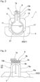
Fig. 3 is a cross-sectional view showing a surrounding area of the dome part ofFig. 2 in an enlarged scale; and -
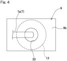
Fig. 4 is a plan view showing a support structure body used in the liquefied gas storage ship shown inFig. 1 . - Hereinafter, one preferable embodiment of the present invention will be described with reference to the drawings.
Fig. 1 shows a liquefiedgas storage ship 1 according to one embodiment of the present invention. The liquefiedgas storage ship 1 includes ahull 3 that floats on water, atank 5 that is installed in thehull 3 for storing liquefied gas, a pipe that is mounted to the tank 5 (in this example, atransport pipe 7 for transporting the liquefied gas between the inside and the outside of the tank 5), and asupport structure body 9 that supports a portion of thetransport pipe 7 extending to the outside of thetank 5. - In this specification, the term "liquefied gas storage ship" refers to a ship having a function of storing liquefied gas. The liquefied
gas storage ship 1 in the present embodiment is a liquefied gas carrier ship. However, in addition to the liquefied gas carrier ship, the liquefied gas storage ship also includes, for example, a liquefied gas fuel ship, a bunkering ship that supplies liquefied gas to other ships, and the like. - In this embodiment, two
tanks 5 are installed in thehull 3 of the liquefiedgas storage ship 1. These twotanks 5 are arranged in the ship length direction of thehull 3. However, the number oftanks 5 mounted in thehull 3 may be one, or three or more. Since the configuration of thetanks 5 may be the same, only one of thetanks 5 will be described in this specification. - The liquefied gas stored in the
tank 5 may be, for example, liquefied petroleum gas (LPG, about -45°C), liquefied ethylene gas (LEG, about -100°C), liquefied natural gas (LNG, about -160°C), liquefied hydrogen (LH2, about -250°C), and liquefied helium (LHe, about -270°C). In this embodiment, liquefied hydrogen is stored in thetank 5. - In the present embodiment, as shown in
Fig. 2 , thetank 5 is configured as a double-shell tank 5 including an inner shell and an outer shell. For example, there is a vacuum thermal insulation layer between the inner shell and the outer shell. However, the configuration of thetank 5 is not limited to this example. For example, thetank 5 may be a single-shell tank 5 covered by a heat insulating material. The heat insulating material may include, for example, a plurality of vacuum heat insulating panels or a plurality of foam panels. - The
tank 5 includes a portion exposed upward from thehull 3, and at least the portion is attached to thehull 3 in a displaceable manner. Specifically, in the present embodiment, thetank 5 includes amain body part 11 which is a part for accommodating the liquefied gas, and adome part 13 protruding upward from themain body part 11. Themain body part 11 is covered by thehull 3. In this example, themain body part 11 is covered by atank cover 15. Specifically, thetank cover 15 is fixed to theupper deck 17, which is a part of thehull 3, so as to be substantially immovable relative to theupper deck 17. Therefore, thetank cover 15 is also formed as a part of thehull 3. Thetank cover 15 includes a top wall formed with an opening through which thedome part 13 is inserted. Through the opening of thetank cover 15, thedome part 13 protrudes above thetank cover 15, that is, thedome part 13 is exposed upward from thetank cover 15. - In the present embodiment, with such a configuration, the
tank 5 includes a portion exposed upward from the hull 3 (in this example, the upper portion of the dome part 13). In the illustrated example, the protruding direction of thedome part 13 is substantially parallel to the vertical direction. The protruding direction, however, may be slightly inclined with respect to the vertical direction. Further, in this example, as shown inFig. 1 , themain body part 11 has a cylindrical shape extending in the horizontal direction. However, the shape of themain body part 11 is not limited to this example and may be, for example, a spherical shape or a rectangular parallelepiped shape. - The
hull 3 is formed with arecess 21 in which thetanks 5 are installed. Therecess 21 is divided into twocells 25 by apartition wall 23 between thetanks 5. On a bottom wall of eachcell 25, a pair ofsaddles 27 are disposed which support themain body part 11 at positions separated from each other in the axial direction of themain body part 11. Each saddle 27 projects from the bottom wall. Thetank 5 is supported on thesaddles 27 so as to be separated from each wall forming thecell 25 of thehull 3. In the present embodiment, with such a configuration, thetank 5 is attached to thehull 3 such that the portion of thetank 5 exposed upward from the hull 3 (in this example, the upper portion of the dome part 13) is displaceable relative to thehull 3. - As shown in
Fig. 3 , thedome part 13 includes aside wall 13a of a cylindrical shape extending substantially in the vertical direction, and alid 13b of a substantially hemispherical shape that closes an upper opening of theside wall 13a. Thedome part 13 is attached with a plurality oftransport pipes 7 for transporting (loading and unloading) liquefied gas to thetank 5. In the figure, only onetransport pipe 7 is shown for the sake of simplicity. Thetransport pipe 7 extends from the inside of thetank 5 to the outside of thetank 5 through thedome part 13. In the following description, a portion of thetransport pipe 7 extending to the outside of thetank 5 may be particularly referred to as a "transport pipeouter portion 7a". In the present embodiment, thetransport pipe 7 penetrates thelid 13b of thedome part 13 in the substantially vertical direction. Further, in this example, thetransport pipe 7 is formed as a double pipe. However, thetransport pipe 7 may be a single pipe. A valve (not shown) for controlling the flow of liquefied gas is provided in the transport pipeouter portion 7a. - In the present embodiment, the above-mentioned
transport pipe 7 will be described as an example of the pipe extending to the outside of thetank 5 through thedome part 13. However, examples of the pipe having such a configuration may include various types of pipes, such as a transport pipe for vaporized gas. - The
dome part 13 is displaced downward with respect to thetank cover 15 due to thermal contraction of thetank 5. Thedome part 13 is connected to thetank cover 15 by a non-illustrated support structure body. - In the present embodiment, the
support structure body 9 that supports the transport pipeouter portion 7a is fixed to thedome part 13 of thetank 5. In other words, thesupport structure body 9 is attached to thedome part 13 of thetank 5 so as to be substantially immovable relative to thedome part 13. Specifically, in the illustrated example, thesupport structure body 9 is fixed on thelid 13b of thedome part 13. - The
support structure body 9 includes anattachment part 9a which is located at the lowermost part and is fixed to thedome part 13, amount part 9b of a flat plate-like shape which is located at the uppermost part and on which the transport pipeouter portion 7a is mounted, and asupport part 9c which is located between theattachment part 9a and themount part 9b to connect and support themount part 9b with respect to theattachment part 9a. As shown inFig. 4 , themount part 9b is formed with aninsertion opening 33 for inserting thetransport pipe 7. In the illustrated example, theinsertion opening 33 is formed in a central portion of themount part 9b. However, the position at which theinsertion opening 33 is formed in themount part 9b is not limited to this example. Provision of theinsertion opening 33 in themount part 9b of thesupport structure body 9 can simplify the arrangement configuration of the transport pipeouter portion 7a. However, it is not essential to form theinsertion opening 33 in themount part 9b. - In the present embodiment, the
mount part 9b of thesupport structure body 9 includes a region protruding with respect to thedome part 13 in a plan view. Specifically, in the illustrated example, themount part 9b of thesupport structure body 9 completely covers thedome part 13 in a plan view. However, only a part of themount part 9b may have a region protruding with respect to thedome part 13 in a plan view. This configuration can secure freedom in the arrangement configuration of the transport pipeouter portion 7a. However, it is not essential for themount portion 9b to include a region protruding with respect to thedome part 13 in a plan view. - In this embodiment, the entire
support structure body 9 is made of low temperature steel (steel for low temperature applications). Alternatively, at least theattachment part 9a of thesupport structure body 9 shown inFig. 3 may be made of low temperature steel. With this configuration, the strength is ensured even when the temperature of theattachment part 9a of thesupport structure body 9 becomes low due to the influence of the tank that stores the liquefied gas. Examples of the low temperature steel used for thesupport structure body 9 may include, but are not limited to, austenitic stainless steel. However, it is not essential to make thesupport structure body 9 from low temperature steel. - In this embodiment, at least a part of the support structure body 9 (a
support portion 9c in this example) has a truss structure. The truss structure may be employed only in a part of thesupport portion 9c, or may be employed in another part of thesupport structure body 9. According to this configuration, the strength of thesupport structure body 9 installed in the limited area above thedome part 13 can be ensured, and thetransport pipe 7 can be reliably supported. However, it is not essential for thesupport structure body 9 to have the truss structure. - As long as the
support structure body 9 is fixed to thedome part 13 of thetank 5, that is, as long as thesupport structure body 9 is attached to thedome part 13 of thetank 5 so as to be substantially immovable relative to thedome part 13, thesupport structure body 9 may be attached to a portion other than the portion on thelid 13b. - According to the liquefied
gas storage ship 1 of the present embodiment described above, thesupport structure body 9 that supports the pipe (transport pipe 7) is mounted to thedome part 13 of thetank 5 to which thetransport pipe 7 is attached. Therefore, relative displacement between thetransport pipe 7 and thesupport structure body 9 can be significantly suppressed as compared with the case where thesupport structure body 9 is mounted to thetank cover 15 or the like of thehull 3. - The type of the
tank 5 included in the liquefiedgas storage ship 1 is not limited to the above-described type of theindependent tank 5. - Although the present invention has been described in terms of the preferred embodiments thereof with reference to the drawings, various additions, modifications, or deletions may be made without departing from the scope of the invention. Accordingly, such variants are included within the scope of the present invention.
-
- 1
- liquefied gas storage ship
- 3
- hull
- 5
- tank
- 7
- transport pipe (pipe)
- 7a
- transport pipe outer portion
- 9
- support structure body
- 13
- dome part
Claims (5)
- A liquefied gas storage ship comprising:a hull;a tank that is installed in the hull and stores liquefied gas, the tank including a dome part protruding upward;a pipe extending from an inside of the tank through the dome part to an outside of the tank; anda support structure body that is fixed to the dome part and supports a portion of the pipe extending to the outside of the tank.
- The liquefied gas storage ship as claimed in claim 1, wherein at least a portion of the support structure body which is fixed to the dome part is made of low temperature steel.
- The liquefied gas storage ship as claimed in claim 1 or 2, wherein the support structure body has a truss structure at least in part.
- The liquefied gas storage ship as claimed in any one of claims 1 to 3, wherein the support structure body includes a mount part on which the pipe is mounted, and the mount part includes a region protruding with respect to the dome part in a plan view.
- The liquefied gas storage ship as claimed in any one of claims 1 to 4, wherein the support structure body includes a mount part on which the pipe is mounted, and the mount part is formed with an insertion opening through which the pipe is inserted.
Applications Claiming Priority (2)
| Application Number | Priority Date | Filing Date | Title |
|---|---|---|---|
| JP2020061456A JP7560952B2 (en) | 2020-03-30 | 2020-03-30 | Liquefied Gas Storage Vessel |
| PCT/JP2021/013313 WO2021200829A1 (en) | 2020-03-30 | 2021-03-29 | Liquefied gas storage ship |
Publications (3)
| Publication Number | Publication Date |
|---|---|
| EP4129814A1 true EP4129814A1 (en) | 2023-02-08 |
| EP4129814A4 EP4129814A4 (en) | 2024-04-17 |
| EP4129814B1 EP4129814B1 (en) | 2026-05-06 |
Family
ID=77930065
Family Applications (1)
| Application Number | Title | Priority Date | Filing Date |
|---|---|---|---|
| EP21780949.0A Active EP4129814B1 (en) | 2020-03-30 | 2021-03-29 | Liquefied gas storage ship |
Country Status (4)
| Country | Link |
|---|---|
| EP (1) | EP4129814B1 (en) |
| JP (1) | JP7560952B2 (en) |
| CN (1) | CN115397727A (en) |
| WO (1) | WO2021200829A1 (en) |
Families Citing this family (3)
| Publication number | Priority date | Publication date | Assignee | Title |
|---|---|---|---|---|
| CN118946499A (en) * | 2022-04-13 | 2024-11-12 | 川崎重工业株式会社 | Liquefied gas storage tank |
| CN115962414A (en) * | 2023-01-04 | 2023-04-14 | 北京市市政四建设工程有限责任公司 | A liquefied gas storage tank installation seat with positioning auxiliary components |
| JP2025154622A (en) * | 2024-03-29 | 2025-10-10 | 三菱造船株式会社 | Liquefied gas supply equipment for ships and ships |
Family Cites Families (12)
| Publication number | Priority date | Publication date | Assignee | Title |
|---|---|---|---|---|
| US3397662A (en) | 1966-06-28 | 1968-08-20 | Mcmullen John J | Hatch arrangement for liquefied gas storage tanks |
| JPS5119234B1 (en) | 1971-04-27 | 1976-06-16 | ||
| JPS5314766B2 (en) | 1972-04-21 | 1978-05-19 | ||
| JPH05157197A (en) * | 1991-12-04 | 1993-06-22 | Tokyo Gas Co Ltd | Nozzle penetration structure on the roof of the cryogenic liquid storage tank |
| US5931111A (en) | 1997-02-21 | 1999-08-03 | Canpotex Shipping Services Limited | Ship hatch cover |
| JP2004028238A (en) | 2002-06-26 | 2004-01-29 | Mitsubishi Heavy Ind Ltd | Tank |
| JP5426266B2 (en) | 2009-05-25 | 2014-02-26 | ジャパンマリンユナイテッド株式会社 | Dome structure of liquefied gas tank |
| JP5670225B2 (en) | 2011-03-03 | 2015-02-18 | 川崎重工業株式会社 | Tank dome flange structure |
| JP6134211B2 (en) | 2013-06-19 | 2017-05-24 | 川崎重工業株式会社 | Double shell tank and liquefied gas carrier |
| JP7231984B2 (en) | 2018-03-02 | 2023-03-02 | 川崎重工業株式会社 | vessel |
| JP7071168B2 (en) | 2018-03-07 | 2022-05-18 | 川崎重工業株式会社 | Liquefied gas tank |
| KR102083562B1 (en) | 2018-07-27 | 2020-03-02 | 삼성중공업 주식회사 | Floating structure |
-
2020
- 2020-03-30 JP JP2020061456A patent/JP7560952B2/en active Active
-
2021
- 2021-03-29 WO PCT/JP2021/013313 patent/WO2021200829A1/en not_active Ceased
- 2021-03-29 CN CN202180024335.5A patent/CN115397727A/en active Pending
- 2021-03-29 EP EP21780949.0A patent/EP4129814B1/en active Active
Also Published As
| Publication number | Publication date |
|---|---|
| KR20220157492A (en) | 2022-11-29 |
| CN115397727A (en) | 2022-11-25 |
| EP4129814B1 (en) | 2026-05-06 |
| JP7560952B2 (en) | 2024-10-03 |
| EP4129814A4 (en) | 2024-04-17 |
| JP2021160400A (en) | 2021-10-11 |
| WO2021200829A1 (en) | 2021-10-07 |
Similar Documents
| Publication | Publication Date | Title |
|---|---|---|
| EP4129814B1 (en) | Liquefied gas storage ship | |
| EP3760530B1 (en) | Ship | |
| JP6364694B2 (en) | Carrier ship | |
| KR20110046627A (en) | Insulation panel joining structure and joining method of standalone liquefied gas tank | |
| KR20160009641A (en) | Double-shelled tank and liquefied gas transport vessel | |
| KR20100133051A (en) | Pump arrangement of the liquefied gas storage tank and offshore structure having the pump arrangement | |
| EP3760910B1 (en) | Double-shell tank and liquefied gas carrier ship | |
| KR20100133097A (en) | Intermediate bulkhead of liquefied gas storage tank arranged in two rows and offshore structure having the intermediate bulkhead | |
| KR20200093819A (en) | Dome barrier structure of independence type storage tank | |
| KR20090010775U (en) | Membrane type LUN storage tank with sloshing reducing means and floating offshore structure having said LUN storage tank | |
| KR100961863B1 (en) | Ship's lanyard storage tank structure with reduced sloshing | |
| JP7466705B2 (en) | Liquefied gas storage tank and vessel containing same | |
| KR20110126575A (en) | Pump arrangement of the liquefied gas storage tank and offshore structure having the pump arrangement | |
| KR102862806B1 (en) | liquefied gas storage tank and ship containing the same | |
| KR20100127470A (en) | Floating structure with multi-row arrangement of storage tank | |
| KR20150093329A (en) | cylindrical membrane tank and ship with cylindrical membrane tank | |
| KR20190026443A (en) | Ballast tank arrangement structure of lngc | |
| KR20100132870A (en) | Passage structure of the liquefied gas storage tank and offshore structure having the passage structure | |
| KR100961864B1 (en) | LUN storage tank having sloshing reducing means and floating offshore structure having the LUN storage tank | |
| KR102947467B1 (en) | High Manganese Steel Cargo Tank Independent Type B and Marine Transportation means having the same | |
| KR102763057B1 (en) | Liquefied gas storage facility | |
| KR102713954B1 (en) | Securing module and insulation panel system for liquefied cargo containment tank including the same | |
| KR20210034741A (en) | Cargo tank | |
| KR101599292B1 (en) | Loading and unloading apparatus for storage tanks and floating structure having the apparatus | |
| KR20260042031A (en) | Liquid cargo carrier |
Legal Events
| Date | Code | Title | Description |
|---|---|---|---|
| STAA | Information on the status of an ep patent application or granted ep patent |
Free format text: STATUS: THE INTERNATIONAL PUBLICATION HAS BEEN MADE |
|
| PUAI | Public reference made under article 153(3) epc to a published international application that has entered the european phase |
Free format text: ORIGINAL CODE: 0009012 |
|
| STAA | Information on the status of an ep patent application or granted ep patent |
Free format text: STATUS: REQUEST FOR EXAMINATION WAS MADE |
|
| 17P | Request for examination filed |
Effective date: 20221024 |
|
| AK | Designated contracting states |
Kind code of ref document: A1 Designated state(s): AL AT BE BG CH CY CZ DE DK EE ES FI FR GB GR HR HU IE IS IT LI LT LU LV MC MK MT NL NO PL PT RO RS SE SI SK SM TR |
|
| DAV | Request for validation of the european patent (deleted) | ||
| DAX | Request for extension of the european patent (deleted) | ||
| A4 | Supplementary search report drawn up and despatched |
Effective date: 20240319 |
|
| RIC1 | Information provided on ipc code assigned before grant |
Ipc: F17C 3/08 20060101ALI20240313BHEP Ipc: B63B 27/24 20060101ALI20240313BHEP Ipc: B63B 25/16 20060101ALI20240313BHEP Ipc: B63B 25/08 20060101AFI20240313BHEP |
|
| GRAP | Despatch of communication of intention to grant a patent |
Free format text: ORIGINAL CODE: EPIDOSNIGR1 |
|
| STAA | Information on the status of an ep patent application or granted ep patent |
Free format text: STATUS: GRANT OF PATENT IS INTENDED |
|
| INTG | Intention to grant announced |
Effective date: 20251212 |
|
| GRAS | Grant fee paid |
Free format text: ORIGINAL CODE: EPIDOSNIGR3 |
|
| GRAA | (expected) grant |
Free format text: ORIGINAL CODE: 0009210 |
|
| STAA | Information on the status of an ep patent application or granted ep patent |
Free format text: STATUS: THE PATENT HAS BEEN GRANTED |
|
| AK | Designated contracting states |
Kind code of ref document: B1 Designated state(s): AL AT BE BG CH CY CZ DE DK EE ES FI FR GB GR HR HU IE IS IT LI LT LU LV MC MK MT NL NO PL PT RO RS SE SI SK SM TR |
|
| REG | Reference to a national code |
Ref country code: CH Ref legal event code: F10 Free format text: ST27 STATUS EVENT CODE: U-0-0-F10-F00 (AS PROVIDED BY THE NATIONAL OFFICE) Effective date: 20260506 Ref country code: GB Ref legal event code: FG4D |
|
| REG | Reference to a national code |
Ref country code: DE Ref legal event code: R096 Ref document number: 602021053868 Country of ref document: DE |
|
| REG | Reference to a national code |
Ref country code: IE Ref legal event code: FG4D |