EP4129808A1 - Saddle-ride type vehicle - Google Patents
Saddle-ride type vehicle Download PDFInfo
- Publication number
- EP4129808A1 EP4129808A1 EP20928033.8A EP20928033A EP4129808A1 EP 4129808 A1 EP4129808 A1 EP 4129808A1 EP 20928033 A EP20928033 A EP 20928033A EP 4129808 A1 EP4129808 A1 EP 4129808A1
- Authority
- EP
- European Patent Office
- Prior art keywords
- airbag
- folded
- retainer
- extending
- inflator
- Prior art date
- Legal status (The legal status is an assumption and is not a legal conclusion. Google has not performed a legal analysis and makes no representation as to the accuracy of the status listed.)
- Granted
Links
Images









Classifications
-
- B—PERFORMING OPERATIONS; TRANSPORTING
- B62—LAND VEHICLES FOR TRAVELLING OTHERWISE THAN ON RAILS
- B62J—CYCLE SADDLES OR SEATS; AUXILIARY DEVICES OR ACCESSORIES SPECIALLY ADAPTED TO CYCLES AND NOT OTHERWISE PROVIDED FOR, e.g. ARTICLE CARRIERS OR CYCLE PROTECTORS
- B62J27/00—Safety equipment
- B62J27/20—Airbags specially adapted for motorcycles or the like
-
- B—PERFORMING OPERATIONS; TRANSPORTING
- B60—VEHICLES IN GENERAL
- B60R—VEHICLES, VEHICLE FITTINGS, OR VEHICLE PARTS, NOT OTHERWISE PROVIDED FOR
- B60R21/00—Arrangements or fittings on vehicles for protecting or preventing injuries to occupants or pedestrians in case of accidents or other traffic risks
- B60R21/02—Occupant safety arrangements or fittings, e.g. crash pads
- B60R21/16—Inflatable occupant restraints or confinements designed to inflate upon impact or impending impact, e.g. air bags
- B60R21/23—Inflatable members
- B60R21/231—Inflatable members characterised by their shape, construction or spatial configuration
-
- B—PERFORMING OPERATIONS; TRANSPORTING
- B60—VEHICLES IN GENERAL
- B60R—VEHICLES, VEHICLE FITTINGS, OR VEHICLE PARTS, NOT OTHERWISE PROVIDED FOR
- B60R21/00—Arrangements or fittings on vehicles for protecting or preventing injuries to occupants or pedestrians in case of accidents or other traffic risks
- B60R21/02—Occupant safety arrangements or fittings, e.g. crash pads
- B60R21/16—Inflatable occupant restraints or confinements designed to inflate upon impact or impending impact, e.g. air bags
- B60R21/23—Inflatable members
- B60R21/237—Inflatable members characterised by the way they are folded
Definitions
- the present invention relates to a saddle-ride type vehicle.
- Patent Literature 1 Conventionally, a saddle-ride type vehicle including an airbag module has been known (see, for example, Patent Literature 1).
- the airbag module is supported by a main frame extending rearward and downward from a head pipe via a stay, and is disposed behind the head pipe.
- Patent Literature 1 JP 6357677 B2
- the airbag module In a case where the airbag module is disposed more adjacent to the head pipe and disposed compactly in a front-rear direction, there is a possibility that the airbag module interferes with a handlebar in a case where the deployment of the airbag is insufficient.
- the present invention has been made in view of the above circumstances, and an object of the present invention is to provide a saddle-ride type vehicle capable of efficiently deploying an airbag.
- a saddle-ride type vehicle includes: a retainer (41) that is provided behind a head pipe (15); an inflator (43); and an airbag (42) that is housed in the retainer (41), inflates by gas (G) discharged by the inflator (43), and is deployed in front of an occupant, in which the airbag (42) is housed in the retainer (41) in a state of being folded bilaterally asymmetrically with respect to a horizontally central portion (C1 and C2) of the airbag (42) in a cross section in a vehicle top view.
- the airbag (42) may be housed in the retainer (41) in a state in which one of left and right sides of the horizontally central portion (C1 and C2) of the airbag (42) is folded in a bellows shape and the other one of the left and right sides is folded in a roll shape in the cross section in the vehicle top view.
- the airbag (42) may be connected to the inflator (43) on the other one of the left and right sides of the horizontally central portion (C1 and C2) of the airbag (42).
- the airbag (42) may be housed in the retainer (41) in a state of including a proximal end-side folded portion (155) folded in a roll shape or a bellows shape, an intermediate-side folded portion (154 and 354) extending from the proximal end-side folded portion (155) and folded above the proximal end-side folded portion (155), and a distal end-side folded portion (153) extending from the intermediate-side folded portion (154 and 354) and folded in a roll shape or a bellows shape in a cross section in a vehicle side view, and the intermediate-side folded portion (154 and 354) may have a plurality of folding-back points (P1, P2, and P3) at which folding is made along the distal end-side folded portion (153) in a front-rear direction of the distal end-side folded portion (153) in the cross section in the vehicle side view.
- P1, P2, and P3 folding-back points
- the retainer (41) may extend along the head pipe (15) and be open upward, and the airbag (42) may have the folding-back points (P1, P2, and P3) provided adjacent to side surfaces (65 and 85) of the retainer (41).
- the retainer (41) may include an L-shaped airbag passage (47) from which the airbag (42) is deployed upward from a left-right direction, and the airbag (42) may be housed in the airbag passage (47) .
- a saddle-ride type vehicle includes: a retainer that is provided behind a head pipe; an inflator; and an airbag that is housed in the retainer, inflates by gas discharged by the inflator, and is deployed in front of an occupant, in which the airbag is housed in the retainer in a state of being folded bilaterally asymmetrically with respect to a horizontally central portion of the airbag in a cross section in a vehicle top view. With this configuration, the airbag can be more efficiently deployed.
- the airbag may be housed in the retainer in a state in which one of left and right sides of the horizontally central portion of the airbag is folded in a bellows shape and the other one of the left and right sides is folded in a roll shape in the cross section in the vehicle top view.
- the airbag may be connected to the inflator on the other one of the left and right sides of the horizontally central portion of the airbag.
- the airbag may be housed in the retainer in a state of including a proximal end-side folded portion folded in a roll shape or a bellows shape, an intermediate-side folded portion extending from the proximal end-side folded portion and folded above the proximal end-side folded portion, and a distal end-side folded portion extending from the intermediate-side folded portion and folded in a roll shape or a bellows shape in a cross section in a vehicle side view, and the intermediate-side folded portion may have a plurality of folding-back points at which folding is made along the distal end-side folded portion in a front-rear direction of the distal end-side folded portion in the cross section in the vehicle side view.
- the airbag can be more efficiently deployed.
- the retainer may extend along the head pipe and be open upward, and the airbag may have the folding-back point provided adjacent to side surfaces of the retainer. With this configuration, the airbag can be more efficiently deployed.
- the retainer may include an L-shaped airbag passage from which the airbag is deployed upward from a left-right direction, and the airbag may be housed in the airbag passage.
- Fig. 1 is a left side view of a motorcycle 1 according to a first embodiment of the present invention.
- the motorcycle 1 is a scooter type saddle-ride type vehicle including a vehicle body frame 10, a steering system 11 that steerably supports a front wheel 2, a power unit 12 supported by a rear portion of the vehicle body frame 10, a rear wheel 3, and a seat 13 on which an occupant sits astride the seat.
- the motorcycle 1 includes a vehicle body cover 14 that covers a vehicle body such as the vehicle body frame 10.
- Fig. 2 is a right side view of the vehicle body frame 10.
- the vehicle body frame 10 includes a head pipe 15 provided at a front end portion of the vehicle body frame 10, a down frame 16 extending rearward and downward from a rear side of the head pipe 15, a pair of left and right lower frames 17 extending rearward from a lower end portion of the down frame 16, and a pair of left and right seat frames 18 extending rearward and upward from rear end portions of the lower frames 17.
- the head pipe 15 and the down frame 16 are positioned at the center of a vehicle width similarly to the front wheel 2.
- the power unit 12 is a unit swing engine including an engine as a drive source of the rear wheel 3 and a swingarm supporting the rear wheel 3 in a swingable manner, the engine and the swingarm being integrated with each other.
- the power unit 12 is supported by the vehicle body frame 10 in a swingable manner via a link mechanism (not illustrated) provided at a front portion of the power unit 12.
- a rear suspension 20 is stretched between a rear portion of the seat frame 18 and a rear end portion of the power unit 12.
- a storage box (not illustrated) supported by the seat frame 18 is disposed below the seat 13.
- the seat 13 is supported by the seat frame 18 via the storage box.
- a pair of left and right step floors 21 having a plate shape and on which feet of the occupant sat on the seat 13 are placed are provided in front of and below the seat 13, and cover the lower frame 17 from above.
- the steering system 11 includes a pair of front forks 11a disposed on the left and right sides of the front wheel 2, a bridge member 11b connecting upper end portions of the left and right front forks 11a in a vehicle width direction, a steering shaft 11c extending upward from the center of the bridge member 11b and rotatably supported by the head pipe 15, a handlebar post 11d fixed to an upper end portion of the steering shaft 11c, and a steering handlebar lie fixed to an upper end of the handlebar post 11d.
- An axis 15a of the head pipe 15 is inclined rearward with respect to a vertical direction in a vehicle side view.
- An axis of rotation of the steering shaft 11c coincides with the axis 15a.
- the handlebar post 11d obliquely extends rearwards and upwards from the head pipe 15 side along the axis 15a.
- the front wheel 2 is supported by an axle 2a connecting lower end portions of the front forks 11a in a left-right direction.
- a front fender 22 that covers the front wheel 2 from above is fixed to the front forks 11a.
- the vehicle body cover 14 includes a front cover 23 that covers the steering system 11 and the head pipe 15 from the front side, an inner cover 24 that covers the steering system 11 and the head pipe 15 from the rear side, a lower cover 25 that covers the lower frame 17 from the outer side below the step floors 21, and a side cover 26 that covers the seat frame 18 from the outer side below the seat 13.
- a straddling space 27 recessed downward when viewed from the side of the vehicle is defined between the inner cover 24 and a front end portion of the seat 13.
- the occupant can straddle the motorcycle 1 through the straddling space 27.
- the motorcycle 1 includes an airbag device 30 that reduces an impact on the occupant.
- the airbag device 30 includes an airbag unit 31, an acceleration sensor (not illustrated) that detects an impact on the motorcycle 1, and an airbag control device (not illustrated) that controls the operation of the airbag unit 31 based on a detection result of the acceleration sensor.
- the airbag unit 31 is disposed on the rear side of the inner cover 24 and is positioned in front of the occupant sat on the seat 13.
- the airbag unit 31 is provided behind the head pipe 15 and below the handlebar 11e, and is positioned at a front side of the straddling space 27.
- a rear portion of the airbag unit 31 is exposed from a notch portion provided in a central portion of the inner cover 24 to the straddling space 27 positioned on the outside of the vehicle body cover 14.
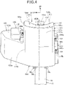
- Fig. 4 is a view of the airbag unit 31 attached to the vehicle body frame 10 as viewed from the rear side.
- Fig. 5 is a right side view of the airbag unit 31 attached to the vehicle body frame 10.
- Fig. 6 is a left side view of the airbag unit 31 in a state in which an exterior member 40 is removed.
- the airbag unit 31 is disposed behind the head pipe 15 and the handlebar post 11d, and is disposed in such a way as to be inclined rearward along the rear side of the head pipe 15 in the vehicle side view.
- the airbag unit 31 is fixed to a stay 32 (see Fig. 2 ) provided at the front end portion of the vehicle body frame 10.
- the stay 32 includes a first stay 33 provided at an upper portion of the head pipe 15 and a second stay 34 provided at an upper portion of the down frame 16.
- the first stay 33 is provided above a connecting portion 16a between the head pipe 15 and an upper end of the down frame 16.
- the second stay 34 is disposed below the first stay 33.
- Fig. 7 is an exploded perspective view of the airbag unit 31.
- the airbag unit 31 includes a box-shaped retainer 41 provided in front of the occupant sat on the seat 13 (see Fig. 1 ), an airbag 42 housed in the retainer 41, an inflator 43 that discharges gas into the airbag 42, a fixing member 44 that fixes the inflator 43 and the airbag 42 to the retainer 41, and the exterior member 40 that covers the retainer 41 from the outer side.
- the retainer 41 of the present embodiment is formed in a box shape by assembling a plurality of parts.
- the retainer 41 is configured by assembling an inflator accommodating portion 51 covering the inflator 43 from the front side, a retainer front half 52 provided behind the head pipe 15, and a retainer rear half 53 provided on the occupant side and joining with the retainer front half 52 and the inflator accommodating portion 51 from the rear side.
- the inflator accommodating portion 51 and the retainer front half 52 are coupled and integrated by welding, for example.
- the inflator accommodating portion 51 and the retainer front half 52 are coupled to form a front case 55 constituting substantially a front half of the retainer 41.
- the retainer rear half 53 is a rear case constituting substantially a rear half of the retainer 41.
- the retainer 41 is formed by coupling the retainer rear half 53 to the front case 55 from the rear side.
- the retainer 41 is a box-shaped member formed in an inverted L shape when viewed from the occupant side (the rear side of the vehicle).
- an L shape means an L shape when the retainer 41 is viewed from the front side or the rear side.
- the retainer 41 has an inverted L shape when viewed from the rear side, but it can be said that the retainer 41 is formed in an L shape.
- the retainer 41 is fixed to the front end portion of the vehicle body frame 10 via the stay 32 (see Fig. 2 ), and is positioned behind the head pipe 15 and the down frame 16.
- the retainer 41 includes a vertically extending portion 45 (see Fig. 6 ) extending vertically, and a side extending portion 46 (see Fig. 6 ) extending outward in the vehicle width direction from a lower side of the vertically extending portion 45.
- the vertically extending portion 45 is a box-shaped portion extending in the vertical direction along the head pipe 15, and is inclined rearward in the vehicle side view.
- the vertically extending portion 45 is positioned at the center of the vehicle width and overlaps with upper end portions of the handlebar post 11d, the head pipe 15, and the down frame 16 from the rear side.
- the side extending portion 46 is a box-shaped portion extending in the vehicle width direction.
- the side extending portion 46 passes through the outer side of the head pipe 15 from the side portion of the vertically extending portion 45 and extends outward in the vehicle width direction and forward.
- the retainer 41 is formed in an L shape in which the side extending portion 46 extends from the vertically extending portion 45.
- An L-shaped airbag passage 47 (see Fig. 7 ) formed by an internal space of the vertically extending portion 45 and an internal space of the side extending portion 46 is formed inside the retainer 41.
- An opening 48 (see Figs. 6 and 7 ) for exposing the airbag passage 47 upward is formed at an upper portion of the vertically extending portion 45.
- the airbag 42 is deployed upward from the opening 48.
- the inflator 43 is disposed in the side extending portion 46 and is disposed offset outward in the vehicle width direction with respect to the head pipe 15 positioned at the center of the vehicle width.
- the retainer front half 52 includes a substantially rectangular front wall portion 65 that is vertically long.
- the front wall portion 65 constitutes a front side surface of the vertically extending portion 45.
- a lower wall portion 68 extending rearward is formed at a lower edge of the front wall portion 65.
- a first side wall 66 extending rearward is formed at an edge of one of the left and right sides of the front wall portion 65.
- a second side wall 67 extending rearward is formed at an upper portion of an edge of the other one of the left and right sides of the front wall portion 65.
- An extending wall portion 69 extending toward the side extending portion 46 and the front side of the vehicle is formed at a lower portion of the edge of the other one of the left and right sides of the front wall portion 65.
- the extending wall portion 69 is continuous with a lower portion of the front wall portion 65.
- An extending portion upper wall 70a extending outward in the vehicle width direction and rearward is formed at an upper edge of the extending wall portion 69.
- the extending portion upper wall 70a is continuous with a lower end of the second side wall 67.
- An extending portion lower wall 70b extending outward in the vehicle width direction and rearward is formed at a lower edge of the extending wall portion 69.
- the extending portion lower wall 70b is continuous with a side portion of the lower wall portion 68.
- a recess 71 formed by denting the retainer front half 52 rearward is formed at a lower end portion of the retainer front half 52.
- the recess 71 is a portion where a lower end portion of the front wall portion 65 and a front portion of the lower wall portion 68 are recessed toward the inside of the retainer 41.
- the recess 71 is provided at a central portion of the front wall portion 65 in a width direction.
- a rear portion of an upper end portion of the down frame 16 is positioned in the recess 71. Therefore, a lower end portion of the retainer 41 can be disposed close to the down frame 16, and the retainer 41 can be disposed compactly.
- a rib-shaped step portion 72 protruding toward the inside of the retainer 41 is provided on an inner surface of the extending wall portion 69.
- the step portion 72 is formed to be longer in the left-right direction than in the vertical direction and extends in the left-right direction in the retainer 41.
- a plurality of step portions 72 are arranged side by side in the vertical direction. The step portion 72 is formed by pushing out a portion of the extending wall portion 69 from the outside to the inside of the retainer 41.
- a fastening portion 73 for fastening the retainer 41 to the stay 32 of the vehicle body frame 10 is provided at a front surface of the front wall portion 65 of the retainer front half 52.
- the fastening portion 73 includes a first fastening member 74 fastened to the first stay 33 of the head pipe 15 and a second fastening member 75 fastened to the second stay 34 of the down frame 16.
- the first fastening member 74 is fastened to the first stay 33 by a fixing tool (not illustrated).
- the second fastening member 75 is fastened to the second stay 34 by a pair of left and right fixing tools 97 (see Figs. 5 and 6 ).
- the inflator accommodating portion 51 is connected to the retainer front half 52.
- the inflator accommodating portion 51 is a box-shaped part whose rear portion is opened rearward.
- the inflator accommodating portion 51 includes a substantially rectangular wall portion 78 covering the inflator 43 from the front side.
- An upper wall portion 79 extending rearward is formed at an upper edge of the wall portion 78.
- a lower wall portion 80 extending rearward is formed at a lower edge of the wall portion 78.
- An outer side wall portion 81 extending rearward is formed at an outer side edge of the wall portion 78 in the vehicle width direction.
- An inner side wall portion 82 extending rearward is formed on an inner side edge of the wall portion 78 in the vehicle width direction.
- the upper wall portion 79 overlaps with the extending portion upper wall 70a of the retainer front half 52 from above, the lower wall portion 80 overlaps with the extending portion lower wall 70b of the retainer front half 52 from below, and the inner side wall portion 82 overlaps with the extending wall portion 69 of the retainer front half 52 from the inner side in the vehicle width direction.
- the inflator accommodating portion 51 is welded to the retainer front half 52 by a welded fixing portion 51b (fixing portion) which is a portion where the upper wall portion 79, the lower wall portion 80, and the inner side wall portion 82 overlap with the retainer front half 52 from the outer side.
- fixing portion 51b fixing portion
- a main body accommodating portion 78a (see Fig. 6 ) formed by making a central portion of the wall portion 78 bulge forward is formed in the wall portion 78 of the inflator accommodating portion 51.
- a receiving surface portion 78b for receiving the inflator 43 is formed around the main body accommodating portion 78a.
- a plurality of fixing hole portions (not illustrated) penetrating in the thickness direction are formed in the receiving surface portion 78b.
- a tubular inflator main body 43a of the inflator 43 that ejects gas is accommodated in the main body accommodating portion 78a.
- a flange portion 43b extending in a radial direction from an outer circumference of a rear portion of the inflator main body 43a abuts on the receiving surface portion 78b.
- the flange portion 43b is sandwiched between the receiving surface portion 78b and the frame-shaped fixing member 44.
- the inflator 43 is fastened to an inner surface of the wall portion 78 by a fixing tool 83 (see Fig. 6 ) inserted into the fixing hole portions (not illustrated) of the fixing member 44, the flange portion 43b, and the receiving surface portion 78b.
- the wall portion 78 is an inflator support portion that supports the inflator 43.
- the inflator 43 is disposed on the inner surface of the wall portion 78 in a direction in which an axis 43c of the tubular inflator main body 43a is directed in the front-rear direction of the vehicle in the vehicle side view.
- the wall portion 78 to which the flange portion 43b is fixed is slightly inclined rearward with respect to the vertical direction in the vehicle side view. Therefore, the axis 43c extends rearward and downward in the vehicle side view.
- the inclination of the axis 43c in the vehicle side view is smaller than 45° with respect to the horizontal.
- the inflator 43 is disposed in a direction in which the axis 43c becomes closer to the center of the vehicle width toward the rear side of the vehicle in plan view viewed from above.
- the inflator 43 ejects gas from a plurality of gas ejection ports 43d (see Fig. 7 ) provided in the outer circumference of the inflator main body 43a behind the flange portion 43b.
- the frame-shaped fixing member 44 surrounds the gas ejection ports 43d. The gas ejected from the gas ejection ports 43d is guided by an inner surface of the fixing member 44 to flow rearward.
- a wire passage hole 79a is provided in the lower wall portion 80 of the inflator accommodating portion 51.
- a wire 49 (see Fig. 6 ) connecting the inflator 43 to the airbag control device passes through the wire passage hole 79a.
- the retainer rear half 53 includes a substantially rectangular rear wall portion 85 that is a vertically long plate.
- the rear wall portion 85 constitutes a rear side surface of the vertically extending portion 45.
- a side rear wall portion 86 extending outward in the vehicle width direction is formed at a lower-left portion of the rear wall portion 85.
- the side rear wall portion 86 constitutes a rear side surface of the side extending portion 46.
- An extending portion side wall 87 extending forward and outward in the vehicle width direction is formed at an edge portion of the outer side of the side rear wall portion 86 in the vehicle width direction.
- a first side wall 88 extending forward from a side edge of a side opposite from the side extending portion 46 is formed at a side edge of one of the left and right sides of the rear wall portion 85.
- the second side wall 89 extending forward from a side edge of a side adjacent to the side extending portion 46 is formed at a side edge of the other one of the left and right sides of the rear wall portion 85.
- the second side wall 89 is formed at an upper portion of the rear wall portion 85.
- the retainer rear half 53 includes a lower wall portion 90 (see Fig. 6 ) extending forward from a lower edge of the rear wall portion 85, a lower edge of the side rear wall portion 86, and a lower edge of the extending portion side wall 87, and an extending portion upper wall 91 extending forward from an upper edge of the side rear wall portion 86 and an upper edge of the extending portion side wall 87.
- the extending portion upper wall 91 is continuous with a lower end of the second side wall 89.
- the side rear wall portion 86 of the retainer rear half 53 faces a rear surface 43e of the inflator main body 43a.
- the axis 43c of the inflator main body 43a intersects the side rear wall portion 86 of the retainer 41.
- a stepped shape 93 protruding toward the inside of the retainer 41 is provided on an inner surface of the side rear wall portion 86.
- the stepped shape 93 is formed in a rib shape longer in the left-right direction than in the vertical direction, and extends in the left-right direction in the retainer 41.
- a plurality of stepped shapes 93 are arranged side by side in the vertical direction.
- the plurality of stepped shapes 93 arranged side by side in the vertical direction guide a flow of the gas ejected from the inflator 43 in the vehicle width direction.
- the retainer front half 52 of the front case 55 includes the first fixing piece 56a and the second fixing piece 57a extending outward in the vehicle width direction from the first side wall 66.
- the retainer rear half 53 includes the first fixing piece 56b and the second fixing piece 57b extending outward in the vehicle width direction from the first side wall 88.
- the first fixing piece 56a and the first fixing piece 56b constitute first fixing portions 56a and 56b.
- the first fixing piece 56a and the first fixing piece 56b are fastened to each other by fasteners (not illustrated) inserted into the first fixing portions 56a and 56b from the rear side.
- the second fixing piece 57a and the second fixing piece 57b constitute second fixing portions 57a and 57b.
- the second fixing piece 57a and the second fixing piece 57b are fastened to each other by fasteners (not illustrated) inserted into the second fixing portions 57a and 57b from the rear side.
- the retainer front half 52 includes a third fixing piece 58a extending downward from the lower wall portion 68.
- the third fixing piece 58a is a connecting portion of the second fastening member 75, and is formed integrally with the second fastening member 75.
- the retainer rear half 53 includes a third fixing piece 58b extending downward from a lower portion of the rear wall portion 85 in the lower wall portion 90.
- the third fixing piece 58a and the third fixing piece 58b constitute a third fixing portion 58 (see Fig. 6 ).
- the third fixing piece 58a and the third fixing piece 58b are fastened to each other by a fastener 58c (see Fig. 6 ) inserted into the third fixing portion 58 from the rear side.
- the retainer front half 52 includes a fourth fixing piece 59a extending outward in the vehicle width direction from the second side wall 67.
- the retainer rear half 53 includes a fourth fixing piece 59b extending outward in the vehicle width direction from the second side wall 89.
- the fourth fixing piece 59a and the fourth fixing piece 59b constitute a fourth fixing portion 59 (see Fig. 6 ).
- the fourth fixing piece 59a and the fourth fixing piece 59b are fastened to each other by a fastener 59c inserted into the fourth fixing portion 59 from the rear side.
- the inflator accommodating portion 51 of the front case 55 includes a fifth fixing piece 60a and a sixth fixing piece 61a extending upward from the upper wall portion 79.
- the retainer rear half 53 includes a fifth fixing piece 60b and a sixth fixing piece 61b extending upward from the extending portion upper wall 91.
- the fifth fixing piece 60a and the fifth fixing piece 60b constitute a fifth fixing portion 60 (see Fig. 6 ).
- the fifth fixing piece 60a and the fifth fixing piece 60b are fastened to each other by a fastener 60c (see Fig. 6 ) inserted into the fifth fixing portion 60 from the rear side.
- the sixth fixing piece 61a and the sixth fixing piece 61b constitute a sixth fixing portion 61 (see Fig. 6 ).
- the sixth fixing piece 61a and the sixth fixing piece 61b are fastened to each other by a fastener 61c (see Fig. 6 ) inserted into the sixth fixing portion 61 from the rear side.
- the inflator accommodating portion 51 includes a seventh fixing piece 62a and an eighth fixing piece 63a extending downward from the lower wall portion 80.
- the retainer rear half 53 includes a seventh fixing piece 62b and an eighth fixing piece 63b extending downward from a lower portion of the side rear wall portion 86 in the lower wall portion 90.
- the seventh fixing piece 62a and the seventh fixing piece 62b constitute a seventh fixing portion 62 (see Fig. 6 ).
- the seventh fixing piece 62a and the seventh fixing piece 62b are fastened to each other by a fastener 62c (see Fig. 6 ) inserted into the seventh fixing portion 62 from the rear side.
- the eighth fixing piece 63a and the eighth fixing piece 63b constitute an eighth fixing portion 63 (see Fig. 6 ).
- the eighth fixing piece 63a and the eighth fixing piece 63b are fastened to each other by a fastener 63c inserted into the eighth fixing portion 63 from the rear side.
- the inflator accommodating portion 51 includes a ninth fixing piece 64a extending outward in the vehicle width direction from a front surface of the wall portion 78.
- a distal end portion 64a1 of the ninth fixing piece 64a is bent rearward, and the distal end portion 64a1 is positioned outside the outer side wall portion 81.
- the retainer rear half 53 includes a ninth fixing piece 64b extending forward from the extending portion side wall 87.
- the ninth fixing piece 64a and the ninth fixing piece 64b constitute a ninth fixing portion 64 (see Fig. 6 ).
- the ninth fixing piece 64a and the ninth fixing piece 64b are fastened to each other by a fastener 64c (see Fig. 6 ) inserted into the ninth fixing portion 64 from the outer side.
- the retainer 41 can be separated into the front case 55 and the retainer rear half 53 by fastening and unfastening the fixing portions 56a to 57b and 53 to 64. This contributes to improvement in assemblability of the airbag device 30.
- the retainer rear half 53 overlaps with the front case 55 from the outer side. That is, in a state where the fixing portions 56 to 64 are fastened, the first side wall 88 overlaps with the first side wall 66 from the outer side, the second side wall 89 overlaps with the second side wall 67 from the outer side, the lower wall portion 90 overlaps with the lower wall portion 68, the extending portion lower wall 70b, and the lower wall portion 80 from the outer side, the extending portion upper wall 91 overlaps with the extending portion upper wall 70a and the upper wall portion 79 from the outer side, and the extending portion side wall 87 overlaps with the outer side wall portion 81 from the outer side.
- the airbag 42 is housed in the L-shaped airbag passage 47 in the retainer 41 in a folded state, and is provided from the side extending portion 46 to the vertically extending portion 45.
- the exterior member 40 is attached to the retainer 41.
- the exterior member 40 is formed in such a way as to cover substantially the entire surface of the retainer 41 except for a lower surface of the retainer 41.
- the exterior member 40 includes a cover 100 that covers the retainer 41, and a lid portion 103 (lid) that covers the opening 48 at the upper surface of the retainer 41 from above, the cover 100 and the lid portion 103 being integrated with each other.
- the cover 100 is provided on a lower side of the lid portion 103.
- the cover 100 includes a vertically extending portion cover portion 101 that covers the vertically extending portion 45 and a side extending portion cover portion 102 that covers the side extending portion 46, the vertically extending portion cover portion 101 and the side extending portion cover portion 102 being integrated with each other.
- a fixing portion housing portion 105 formed by making a portion of the first side surface portion 101c bulge outward in the vehicle width direction is provided.
- the first fixing portions 56a and 56b (see Fig. 7 ) and the second fixing portions 57a and 57b (see Fig. 7 ) are housed in the fixing portion housing portion 105.
- a first attachment hole 105a penetrating through a front surface of the fixing portion housing portion 105 is provided in an upper portion of the front surface of the fixing portion housing portion 105.
- a cover fastener 108 is inserted into the first attachment hole 105a.
- the cover fastener 108 is fastened to a first cover fixing hole portion 56d (see Fig. 7 ) provided in an upper portion of the first fixing piece 56b.
- a second attachment hole 105b penetrating through the front surface of the fixing portion housing portion 105 is provided in the front surface of the fixing portion housing portion 105 below the first attachment hole 105a.
- a cover fastener 109 is inserted into the second attachment hole 105b.
- the cover fastener 109 is fastened to a second cover fixing hole portion 57d provided in an upper portion of the second fixing piece 57b.
- a fixing portion housing portion 106 formed by making a portion of the side upper surface portion 102c bulge upward is provided.
- the fourth fixing portion 59, the fifth fixing portion 60, and the sixth fixing portion 61 are housed in the fixing portion housing portion 106.
- a third attachment hole 106a (see Fig. 7 ) penetrating through a front surface of the fixing portion housing portion 106 is provided in the front surface.
- a cover fastener 110 is inserted into the third attachment hole 106a.
- the cover fastener 110 is fastened to a third cover fixing hole portion 59d (see Fig. 6 ) provided in an upper portion of the fourth fixing piece 59b.
- the exterior member 40 is fastened to the retainer 41 by the cover fasteners 108, 109, and 110.
- the exterior member 40 of the present embodiment is engaged with a claw portion (not illustrated) provided on the front surface of the retainer 41, and is attached to the retainer 41 in a state where a front portion of the exterior member 40 is prevented from coming off upward.
- a handlebar holder 11f that supports the handlebar 11e is provided at an upper end portion of the handlebar post 11d.
- the handlebar holder 11f has a disk shape in plan view viewed from above, and the handlebar 11e is fixed to an upper surface of the handlebar holder 11f.
- the airbag unit 31 is disposed in such a way that the lid portion 103 of the exterior member 40 is arranged behind the handlebar holder 11f.
- the lid portion 103 of the exterior member 40, a rear surface portion 101a, a side rear surface portion 102a, the fixing portion housing portion 105, and the fixing portion housing portion 106 are exposed to the straddling space 27.
- a lid recessed portion 103a recessed downward is provided at a front portion of the lid portion 103 to avoid a rear portion of the handlebar holder 11f.
- a front edge of the lid recessed portion 103a is formed in an arc shape in accordance with the shape of the rear portion of the handlebar holder 11f.
- the rear portion of the handlebar holder 11f is disposed in the lid recessed portion 103a. Therefore, the lid portion 103 can be disposed close to the handlebar holder 11f in the front-rear direction of the vehicle.
- the exterior member 40 includes a tear line 115 as a cleavage portion broken by the deployed airbag 42.
- the tear line 115 is a groove-shaped fragile portion formed to have a plate thickness smaller than a plate thickness of a portion of the exterior member 40 around the tear line 115.
- the tear line 115 is formed to have a small plate thickness and preferentially cleaves.
- the tear line 115 includes a rear edge 103b of the lid portion 103, left and right side edges 103c of the lid portion 103, and a lid-side tear line 115a provided in a portion excluding a portion of the lid recessed portion 103a in a front edge 103d of the lid portion 103.
- the tear line 115 includes a pair of left and right rear tear lines 115b extending downward along the left and right side edges of the rear surface portion 101a from portions of the left and right end portions of the rear edge 103b in the lid-side tear line 115a.
- the tear line 115 includes a pair of left and right front tear lines (not illustrated) extending downward along the left and right side edges of a front surface portion 101b from the left and right end portions of the front edge 103d in the lid-side tear line 115a.
- the exterior member 40 covers a range from the upper end portion to the lower end portion of the retainer 41, and covers substantially the entire retainer 41 except for the lower surface and a lower-left portion of the front surface of the retainer 41 from the outer side.
- the upper end portion of the retainer 41 is the opening 48
- the lower end portion of the retainer 41 is lower edges of the rear wall portion 85 and the side rear wall portion 86.
- the retainer 41 can be entirely covered from above and surrounded by the exterior member 40, and the waterproofness of the retainer 41 can be improved.
- the inflator 43 ejects gas into the airbag 42 toward the rear side of the vehicle along the axis 43c under the control of the airbag control device.
- the gas discharged from the inflator 43 into the airbag 42 is guided by the side extending portion 46 and the vertically extending portion 45, and flows in an L shape in the airbag passage 47.
- the airbag 42 When the airbag 42 inflates upward by the gas flowing upward in the vertically extending portion 45, the tear line 115 of the exterior member 40 cleaves, the lid portion 103 is opened, and the opening 48 is exposed. Then, the airbag 42 is deployed upward from the opening 48 as illustrated in Fig. 1 by the gas flowing upward.
- the retainer 41 is fastened to the down frame 16 at a lower side position of the retainer 41 via the second fastening member 75.
- the support rigidity of a lower portion of the retainer 41 with respect to the vehicle body frame 10 side is increased, and when the airbag 42 inflates by the gas, a portion of an upper portion of the retainer 41 on the opening 48 side slightly moves toward the occupant side with a portion of the second fastening member 75 as a fulcrum due to the inflation of the airbag 42, and is deformed to widen the opening 48. Therefore, the airbag 42 can be satisfactorily deployed upward.
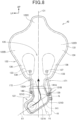
- Fig. 8 is a view of the deployed and inflating airbag 42 as viewed from the rear side (corresponding to the occupant side).
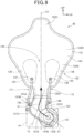
- Fig. 9 is a view of the deployed and inflating airbag 42 as viewed from the front side (a side opposite from the occupant).
- the airbag 42 is a bag including a proximal end portion 121 positioned in the airbag passage 47 (see Fig. 7 ) of the retainer 41 in a deployed state and an outward deployment portion 122 positioned outside the airbag passage 47 in a deployed state, the proximal end portion 121 and the outward deployment portion 122 being integrated with each other.
- the outward deployment portion 122 is formed bilaterally symmetrically with respect to a center line (left-right center line) C1 of the outward deployment portion 122 in the width direction (left-right direction).
- the airbag 42 is disposed in such a way that the center line C1 is positioned on the left side of the center of the vehicle width.
- the airbag 42 is disposed in such a way that the center line C1 is at the same position as a center line 47C (see Figs. 4 to 6 ) of the vertically extending portion 45 of the retainer 41 in the vehicle width direction.
- the outward deployment portion 122 includes a neck portion 122A extending upward from an upper end of the proximal end portion 121, a deployment portion main body 122B extending upward from an upper end of the neck portion 122A, and a bulging portion 122C bulging upward from the center of the upper portion of the deployment portion main body 122B in the width direction.
- the neck portion 122A is a cylindrical portion extending in the vertical direction from the opening 48 of the retainer 41 in a state where the airbag 42 is operated and deployed.
- the deployment portion main body 122B is formed in a fan shape extending upward and having a width in the left-right direction increasing from a lower end which is a connecting portion with the neck portion 122A.
- the deployment portion main body 122B includes a head facing portion 122D having the maximum width in the left-right direction at an upper end portion thereof.
- the head facing portion 122D is a portion assumed to receive the head of the occupant in a state where the airbag 42 is operated and deployed.
- the neck portion 122A, the deployment portion main body 122B, and the bulging portion 122C are provided bilaterally symmetrically with respect to the center line C1.
- the airbag 42 of the present embodiment is formed in a bag shape by a joining structure of a front base fabric (front surface) 123 (see Fig. 9 ) and a rear base fabric (rear surface) 124 (see Fig. 8 ).
- a sewn portion (coupling portion) 131 for forming the joining structure in which the front base fabric 123 and the rear base fabric 124 are sewn together is formed at peripheral edge portions of the front base fabric 123 and the rear base fabric 124.
- the deployment portion main body 122B includes a pair of middle sewn portions 133 and 133 at positions between the neck portion 122A and the head facing portion 122D.
- the middle sewn portions 133 and 133 are provided bilaterally symmetrically with respect to the center line C1.
- the middle sewn portions 133 and 133 are portions where the front base fabric 123 and the rear base fabric 124 of the outward deployment portion 122 are sewn and connected along peripheral edge portions of the middle sewn portions 133 and 133, and the gas G does not pass through the middle sewn portions 133 and 133.
- a throttle portion 135 in which the passage of the gas G becomes narrower than that on the upstream side is formed between the left and right middle sewn portions 133 and 133.
- throttle portions 136 and 136 in which the passage of the gas G becomes narrower than that on the upstream side are formed between left and right side portions of the outward deployment portion 122 and the middle sewn portions 133 and 133.
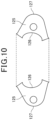
- Fig. 10 is an explanatory view of panels 125 and 125 forming a circumferential length difference.
- the panels 125 and 125 forming a circumferential length difference between the front base fabric 123 and the rear base fabric 124 when viewed from the side are sewn to the sewn portion 131 of the front base fabric 123 and the rear base fabric 124.
- the panels 125 and 125 are formed of fabric similarly to the front base fabric 123 and the rear base fabric 124.
- a pair of panels 125 and 125 are provided on the left and right sides of the neck portion 122A.
- the left panel 125 is illustrated in a left side view
- the right panel 125 is illustrated in a right side view.
- the panels 125 and 125 are configured to be bilaterally symmetrical.
- the panels 125 and 125 are substantially D-shaped in a side view.
- Each of the panels 125 and 125 includes a front edge portion 126 and a rear edge portion 127 facing the front edge portion 126.
- the front edge portion 126 and the rear edge portion 127 are formed in an arc shape recessed rearward, and the front edge portion 126 has a shorter circumferential length than the rear edge portion 127.
- the peripheral edge portion of the front base fabric 123 and the front edge portion 126 of the panel 125 are sewn while facing each other.
- the circumferential length of the peripheral edge portion of the front base fabric 123 corresponds to the circumferential length of the front edge portion 126 of the panel 125 in a side view at a portion sewn to the panel 125.
- a peripheral edge portion of the rear base fabric 124 and the rear edge portion 127 of the panel 125 are sewn while facing each other.
- the circumferential length of the peripheral edge portion of the rear base fabric 124 corresponds to the circumferential length of the rear edge portion 127 of the panel 125 in a side view at a portion sewn to the panel 125.
- the front base fabric 123 is shorter, and the rear base fabric 124 is longer. Since there is a circumferential length difference between the front base fabric 123 and the rear base fabric 124 in a direction along the center line C1, the airbag 42 is easily deployed in a state of being bent toward a certain front side of the front base fabric 123 in the direction along the center line C1 at the time of deployment.
- the panel 125 in the present embodiment is disposed upstream of the deployment portion main body 122B including the head facing portion 122D and greatly expanding in the left-right direction, in a flow direction of the gas G. Therefore, it is possible to deploy the airbag 42 while suppressing the deployment portion main body 122B from interfering with portions of the handlebar 11e positioned on the left and right sides of the handlebar post 11d.
- the proximal end portion 121 connected to the inflator 43 includes a bag left-right extending portion 121A extending in the left-right direction in the side extending portion 46 of the retainer 41 and a bag upward extending portion 121B extending upward from the bag left-right extending portion 121A.
- the bag left-right extending portion 121A extends in the left-right direction from the inflator 43 of the retainer 41 toward the center line C1.
- the bag upward extending portion 121B extends upward while being slightly inclined with respect to the center line C1 in the vertically extending portion 45.
- the outward deployment portion 122 extending upward is continuous with an upper end of the bag upward extending portion 121B.
- the bag left-right extending portion 121A extends toward one side in the vehicle width direction with respect to the center line C1, and is formed to be bilaterally asymmetrical with respect to the center line C1.
- the outward deployment portion 122 is bilaterally symmetrical with respect to the center line C1, but the proximal end portion 121 is provided bilaterally asymmetrically with respect to the center line C1 along the L-shaped airbag passage 47.
- An angle at which an extending direction X1 of the bag left-right extending portion 121A and an extending direction Y1 of the bag upward extending portion 121B intersect is larger than a right angle.
- the proximal end portion 121 is formed in an L shape along the airbag passage 47 of the retainer 41.
- the proximal end portion 121 When housed in the retainer 41, the proximal end portion 121 has a shape curved at a substantially right angle along the airbag passage 47.
- curved portions 121C and 121D are formed at a connecting portion between the bag left-right extending portion 121A and the bag upward extending portion 121B.
- the gas G smoothly flows along the curved portions 121C and 121D.
- a connecting port 121E (see Fig. 9 ) connected to the inflator 43 is provided at a position offset from the center line C1 of the bag left-right extending portion 121A in the vehicle width direction in the front base fabric 123 of the proximal end portion 121.
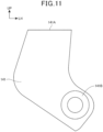
- Fig. 11 is a front view of a loop diffuser 141.
- the airbag 42 includes the loop diffuser 141 that guides the gas G.
- the loop diffuser 141 is formed in an L-shaped bag shape including an opening 141A at one end thereof. A peripheral edge portion of the loop diffuser 141 is closed except for the opening 141A.
- the loop diffuser 141 is disposed in the gas flow path of the proximal end portion 121 and extends from the inflator 43 to a lower end portion of the outward deployment portion 122.
- the loop diffuser 141 is coupled to the airbag 42 by being sewn to an inner surface of the proximal end portion 121.
- the loop diffuser 141 includes a connecting portion 141B connected to the inflator 43.
- the connecting portion 141B is connected to the inflator 43 in such a way as to overlap with the connecting port 121E of the bag left-right extending portion 121A from the inner side.
- the gas G discharged from the inflator 43 directly flows into the bag of the loop diffuser 141 from the connecting portion 141B.
- the gas G flowing into the loop diffuser 141 flows along the loop diffuser 141 and flows into the outward deployment portion 122 from the opening 141A.
- the opening 141A is disposed in such a way that the gas G discharged from the opening 141A flows upward.
- the flow direction of the gas G from the inflator 43 can be controlled by the loop diffuser 141, a filling procedure for filling the airbag 42 with the gas G can be controlled, and the airbag 42 can be efficiently deployed upward.
- a right pipe portion 137 is formed at a lower portion of an inner peripheral side of the right middle sewn portion 133.
- a left pipe portion 138 is formed at a lower portion of an inner peripheral side of the left middle sewn portion 133.
- the pipe portions 137 and 138 sew the front base fabric 123 and the rear base fabric 124 in a circular shape.
- a right side tab 139 and a left side tab 140 are provided on the proximal end portion 121.
- the side tabs 139 and 140 are fabrics separate from the front base fabric 123 and the rear base fabric 124.
- the side tabs 139 and 140 are disposed between the front base fabric 123 and the rear base fabric 124 and are sewn to the sewn portion 131.
- the right side tab 139 is sewn in a state of extending toward one side in the left-right direction from the right curved portion 121D of the proximal end portion 121.
- the right side tab 139 overlaps with a line L2 passing through the center of the inflator 43 and extending along the longitudinal direction X1 of the bag left-right extending portion 121A in a vehicle front view.
- the left side tab 140 is sewn in a state of extending toward the other side in the left-right direction from the left curved portion 121C of the proximal end portion 121.
- the left side tab 140 is disposed above the right side tab 139 in the vehicle front view.
- Anchoring bodies 171 and 172 are disposed between the pipe portions 137 and 138 and the side tabs 139 and 140.
- the anchoring bodies 171 and 172 are formed of a belt-shaped fabric extending in the vertical direction.
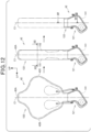
- Fig. 12 is an explanatory view of a folding order of the airbag 42.
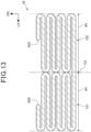
- Fig. 13 is a schematic view illustrating a cross section of the airbag 42 in a vehicle side view corresponding to a cross section taken along line XIII-XIII in Fig. 12 .
- Fig. 14 is a schematic view illustrating a cross section of the airbag 42 in a vehicle top view corresponding to a cross section taken along line XIV-XIV in Fig. 12 .
- a center line C2 is a center line extending in the front-rear direction orthogonal to the center line C1.
- the center line C1 corresponds to the center line in the vehicle front view
- the center line C2 corresponds to the center line in the left-right direction in the vehicle top view.
- the airbag 42 is schematically illustrated as a single layer structure for convenience of explanation.
- the airbag 42 is housed in the retainer 41 in a folded state.
- the outward deployment portion 122 is folded in a direction orthogonal to the center line C1 in the vehicle front view. It may be considered that the outward deployment portion 122 is folded in a direction orthogonal to the center line C2 in the vehicle top view. In the present embodiment, the outward deployment portion 122 is folded in a bellows shape bilaterally symmetrically with respect to the center line C1 (C2).
- a portion of the outward deployment portion 122 that is positioned on a left end 42B side of the center line C1 (C2) is folded forward with a position corresponding to a predetermined length W1 on the left side of the center line C1 (C2) as a folding-back point (folding-back position).
- the portion of the outward deployment portion 122 that is positioned on the left end 42B side is folded forward with a position corresponding to the center line C1 (C2) as a folding-back point.
- the portion of the outward deployment portion 122 that is positioned on the left end 42B side is folded forward with the position corresponding to the predetermined length W1 on the left side of the center line C1 (C2) as a folding-back point.
- the portion of the outward deployment portion 122 that is positioned on the left end 42B side is folded forward a plurality of times and folded in a bellows shape with the position corresponding to the predetermined length W1 on the left side of the center line C1 (C2) and the position corresponding to the center line C1 (C2) as the folding-back points.
- a portion of the outward deployment portion 122 that is positioned on the right end 42C side is folded in the same manner as the portion of the outward deployment portion 122 that is positioned on the left end 42B side except that the portion of the outward deployment portion 122 that is positioned on the right end 42C side is laterally reversed. That is, the portion of the outward deployment portion 122 that is positioned on the right end 42C side is folded forward a plurality of times and folded in a bellows shape with a position corresponding to the predetermined length W1 on the right side of the center line C1 (C2) and the position corresponding to the center line C1 (C2) as folding-back points.
- a pair of left and right bellows-shaped portions 151 and 152 are formed in the airbag 42.
- the sum of the width (length) W1 of the bellows-shaped portion 151 in the left-right direction and the width W1 of the bellows-shaped portion 152 in the left-right direction is a width at which the airbag 42 can be accommodated in the vertically extending portion 45 of the retainer 41.
- folding the outward deployment portion 122 in a bellows shape refers to folding performed in such a way as to overlapping linearly extending portions while switching a folding-back direction.
- the outward deployment portion 122 is folded in a direction along the center line C1. That is, the bellows-shaped portions 151 and 152 are folded in a direction along the center line C1 of the airbag 42.
- an upper end 42A is bent forward and formed in a roll shape by a preset number of turns (a preset number of times).
- folding the outward deployment portion 122 in a roll shape refers to folding performed in such a way as to fold back an end portion of the outward deployment portion 122 or the folding-back point of the outward deployment portion 122 as an end portion, and roll the folded-back portion in a certain direction in such a way as to wrap the folded-back portion.
- a distal end-side folded portion 153 folded in a roll shape is formed in the airbag 42.
- a virtual line L1 in the longitudinal direction is formed along a folded portion including the upper end 42A in a cross section in the vehicle side view on the distal end-side folded portion 153.
- the virtual line L1 extends in the vertical direction.
- the distal end-side folded portion 153 is folded back in the opposite direction (downward) on the front side.
- a second folding-back point P2 is formed on the front side of the distal end-side folded portion 153, and a second folded-back portion 154B is formed.
- the second folded-back portion 154B includes a portion extending downward from the second folding-back point P2 along the virtual line L1.
- the outward deployment portion 122 is folded in such a way as to wrap the distal end-side folded portion 153, whereby the panel 125 is moved to the rear side of the distal end-side folded portion 153, and folded back in the opposite direction (downward) at the position of the panel 125.
- a first folding-back point P1 is formed on the rear side of the distal end-side folded portion 153, and a first folded-back portion 154A is formed.
- the first folded-back portion 154A includes a portion of the outward deployment portion 122 that extends from the first folding-back point P1 along the virtual line L1.
- a portion closer to the proximal end portion 121 than to the first folded-back portion 154A is folded back a plurality of times in the front-rear direction and folded in a bellows shape.
- a proximal end-side folded portion 155 is formed below the first folded-back portion 154A.
- An intermediate-side folded portion 154 is formed between the proximal end-side folded portion 155 and the distal end-side folded portion 153.
- the intermediate-side folded portion 154 of the first embodiment includes the first folded-back portion 154A and the second folded-back portion 154B.
- the airbag 42 is housed in the vertically extending portion 45 of the retainer 41 in a state of including the proximal end-side folded portion 155, the intermediate-side folded portion 154, and the distal end-side folded portion 153.
- the virtual line L1 in the longitudinal direction of the distal end-side folded portion 153 is disposed along the center line 47C of the vertically extending portion 45.
- the first folding-back point P1 is disposed adjacent to the rear wall portion (side surface) 85 of the retainer 41, and the first folded-back portion 154A is sandwiched between the distal end-side folded portion 153 and the rear wall portion 85.
- the second folding-back point P2 is disposed adjacent to the front wall portion (side surface) 65 of the retainer 41, and the second folded-back portion 154B is sandwiched between the distal end-side folded portion 153 and the front wall portion 65.
- a connecting portion P0 where the distal end-side folded portion 153 and the intermediate-side folded portion 154 are connected is set to a position where the virtual line L1 of the distal end-side folded portion 153 and the outermost periphery portion of the outward deployment portion 122 of the distal end-side folded portion 153 intersect each other.
- a height H1 of the first folding-back point P1 is set to a length from the connecting portion P0 to the first folding-back point P1 along the virtual line L1.
- a height H2 of the second folding-back point P2 is set to a length from the connecting portion P0 to the second folding-back point P2 along the virtual line L1.
- the height H1 of the first folding-back point P1 is higher than the height H2 of the second folding-back point P2.
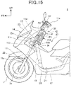
- Fig. 15 is a left side view of a main part of the motorcycle 1 in a state before the airbag 42 is deployed.
- Fig. 16 is a continuation of Fig. 15 and is an explanatory view illustrating a state in which the airbag 42 starts to be deployed.
- Fig. 17 is a continuation of Fig. 16 and is an explanatory view illustrating a state in which the first folded-back portion 154A of the airbag 42 starts to be deployed.
- Fig. 18 is a continuation of Fig. 17 and is an explanatory view illustrating a state in which the second folded-back portion 154B starts to be deployed.
- the gas G is injected into the airbag 42.
- the airbag 42 inflates by a pressure of the gas G and deployed upward.
- the gas G is injected to the loop diffuser 141.
- the gas G is guided by the loop diffuser 141 to move through the L-shaped proximal end portion 121.
- the gas G having passed through the proximal end portion 121 enters the outward deployment portion 122 to deploy the outward deployment portion 122.
- the outward deployment portion 122 supported by the proximal end portion 121 is easily deployed in a stable posture.
- the proximal end-side folded portion 155, the intermediate-side folded portion 154, and the distal end-side folded portion 153 are deployed in the vehicle side view, and the bellows-shaped portions 151 and 152 are deployed in the left-right direction.
- the outward deployment portion 122 is deployed rearward, as illustrated in Fig. 17 , the first folded-back portion 154A is deployed immediately below the handlebar 11e in the vehicle side view.
- the bellows-shaped portions 151 and 152 are deployed in the left-right direction.
- the panels 125 and 125 are sewn to the first folded-back portion 154A, and a circumferential length difference is generated between the front base fabric 123 and the rear base fabric 124. Therefore, the airbag 42 that pops out rearward from the retainer 41 is easily deployed upward after passing below the handlebar 11e, and is easily deployed while suppressing the airbag 42 from coming into contact with the handlebar 11e.
- the second folded-back portion 154B is deployed behind the handlebar holder 11f in the vehicle side view.
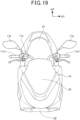
- the bellows-shaped portions 151 and 152 are deployed in a well-balanced manner in the left-right direction, the airbag 42 is unfolded outward in such a way as to be wider than the seat 13 in the left-right direction, and is deployed to the vicinity of bases (inner ends of left and right grips 11e1 and 11e1 of the handlebar 11e in the vehicle width direction) of rearview mirrors 11g and 11g.
- the distal end-side folded portion 153 is disposed behind the second folded-back portion 154B, and the distal end-side folded portion 153 receives a force to move toward the occupant side (rear side) from the deployed second folded-back portion 154B.
- the airbag 42 is efficiently deployed while being suppressed from coming into contact with the handlebar 11e (see Fig. 1 ).
- the saddle-ride type vehicle includes: the retainer 41 that is provided behind the head pipe 15; the inflator 43; and the airbag 42 that is housed in the retainer 41, inflates by the gas G discharged by the inflator 43, and is deployed in front of the occupant, in which the airbag 42 is housed in the retainer 41 in a state of including the proximal end-side folded portion 155 folded in a bellows shape, the intermediate-side folded portion 154 extending from the proximal end-side folded portion 155 and folded above the proximal end-side folded portion 155, and the distal end-side folded portion 153 extending from the intermediate-side folded portion 154 and folded in a roll shape or a bellows shape in the cross section in the vehicle side view, and the intermediate-side folded portion 154 has the plurality of folding-back points P1 and P2 at which folding is made along the distal end-side folded portion 153 in the front
- the folding-back points P1 and P2 are provided on the front side and the rear side of the distal end-side folded portion 153. Therefore, it is possible to adjust the direction in which the distal end-side folded portion 153 is deployed.
- the retainer 41 extends along the head pipe 15 and is open upward, and the airbag 42 may have the folding-back points P1 and P2 provided adjacent to the front wall portion 65 and the rear wall portion 85 constituting the side surfaces of the retainer 41. Therefore, the airbag 42 can be more efficiently deployed.
- the airbag 42 is folded bilaterally symmetrically with respect to the center line C1 of the airbag 42 in a cross section in the vehicle top view. Therefore, the airbag 42 can be deployed in a well-balanced manner in the left-right direction.
- the bilaterally symmetrically folded airbag 42 has a bellows shape. Therefore, the airbag 42 can be easily folded and housed in the retainer 41.
- the retainer 41 includes the L-shaped airbag passage 47 from which the airbag 42 is deployed upward from the left-right direction, and the airbag 42 is housed in the airbag passage 47. Therefore, it is possible to efficiently deploy the airbag 42 disposed in the L-shaped airbag passage 47.
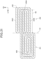
- Fig. 21 is an explanatory view of a second embodiment and is a view corresponding to Fig. 13 of the first embodiment.
- an outward deployment portion 122 is folded bilaterally asymmetrically with respect to center lines (horizontally central portions) C1 and C2.
- the airbag 42 of the second embodiment includes a roll-shaped portion 251 and an irregular bellows-shaped portion 252 instead of the bellows-shaped portions 151 and 152 according to the first embodiment.
- a portion of the outward deployment portion 122 that is positioned on a left end 42B side of the center line C1 (C2) is folded in a roll shape in a manner in which the left end 42B is bent rearward.
- the roll-shaped portion 251 folded in a roll shape is formed on the left side (one side in the left-right direction) of the center line C1 (C2) of the airbag 42.
- a portion of the outward deployment portion 122 that is positioned on a right end 42C side of the center line C1 (C2) is folded rearward a plurality of times and folded in a bellows shape with a position corresponding to a predetermined length W2 on the right side of the center line C1 (C2) and a position corresponding to the center line C1 (C2) as folding-back points.
- a bellows-shaped portion 252A is formed.
- the portion of the outward deployment portion 122 that is positioned on the right end 42C side is folded rearward with the position corresponding to the center line C1 (C2) as a folding-back point on the rear side of the bellows-shaped portion 252A, and is folded in such a way as to surround a rear portion, a right portion, and a front portion of the bellows-shaped portion 252A. In this manner, a surrounding portion 252B is formed.
- the portion of the outward deployment portion 122 that is positioned on the right end 42C side is folded forward with the position corresponding to the center line C1 (C2) as a folding-back point at an inner end of a front portion of the surrounding portion 252B. In this manner, a front-side straight portion 252C is formed.
- the irregular bellows-shaped portion 252 of the second embodiment includes the bellows-shaped portion 252A, the surrounding portion 252B, and the front-side straight portion 252C.
- the roll-shaped portion 251 folded in a roll shape is formed on the left side of the center line C1 (C2) on which the inflator 43 is disposed.
- the irregular bellows-shaped portion 252 folded in a bellows shape is formed on the right side of the center line C1 (C2) which is a side away from the inflator 43.
- the gas G is injected into the airbag 42, and in the outward deployment portion 122, the proximal end-side folded portion 155, the intermediate-side folded portion 154, and the distal end-side folded portion 153 are deployed in the vehicle side view, and the roll-shaped portion 251 and the irregular bellows-shaped portion 252 are deployed in the left-right direction.
- the roll-shaped portion 251 and the irregular bellows-shaped portion 252 are deployed in the left-right direction.
- the portion of the airbag 42 that is folded in the roll shape is deployed at a lower speed as compared with the portion of the airbag 42 that is folded in the bellows shape.
- the roll-shaped portion 251 in the left-right direction, is positioned on the inflator 43 side with respect to the center line C1 (C2), and the irregular bellows-shaped portion 252 is positioned on a side opposite from the inflator 43 with respect to the center line C1 (C2). Therefore, the side where the gas G injected from the inflator 43 easily enters is folded in a roll shape. The side where the gas G injected from the inflator 43 hardly enters is folded in a bellows shape. In the second embodiment, it is easy to match deployment times of the left side and the right side (times required for deployment) at different distances from the inflator 43, and it is thus easy to efficiently deploy the airbag 42.
- the saddle-ride type vehicle includes the retainer 41 that is provided behind the head pipe 15, the inflator 43, and the airbag 42 that is housed in the retainer 41, inflates by the gas G discharged by the inflator 43, and is deployed in front of the occupant, in which the airbag 42 is housed in the retainer 41 in a state of being folded bilaterally asymmetrically with respect to the center line C1 (C2) of the airbag 42 in the cross section in the vehicle top view. Therefore, the airbag 42 can be more efficiently deployed.
- the airbag 42 is housed in the retainer 41 in a state in which the right side of the center line C1 (C2) of the airbag 42 is folded in a bellows shape and the left side of the center line C1 (C2) of the airbag 42 is folded in a roll shape in the cross section in the vehicle top view. Therefore, the deployment times of the airbag 42 in the left-right direction can be adjusted.
- the airbag 42 is housed in the retainer 41 in a state of including the proximal end-side folded portion 155 folded in a bellows shape, the intermediate-side folded portion 154 extending from the proximal end-side folded portion 155 and folded above the proximal end-side folded portion 155, and the distal end-side folded portion 153 extending from the intermediate-side folded portion 154 and folded in a roll shape in the cross section in the vehicle side view, and the intermediate-side folded portion 154 has the plurality of folding-back points P1 and P2 at which folding is made along the distal end-side folded portion 153 in the front-rear direction of the distal end-side folded portion 153 in the cross section in the vehicle side view. Therefore, the airbag 42 can be more efficiently deployed.
- the retainer 41 extends along the head pipe 15 and is open upward, and the airbag 42 may have the folding-back points P1 and P2 provided adjacent to the front wall portion 65 and the rear wall portion 85 constituting the side surfaces of the retainer 41. Therefore, the airbag 42 can be more efficiently deployed.
- the retainer 41 includes the L-shaped airbag passage 47 from which the airbag 42 is deployed upward from the left-right direction, and the airbag 42 is housed in the airbag passage 47. Therefore, it is possible to efficiently deploy the airbag 42 disposed in the L-shaped airbag passage 47.
- An airbag 42 of the third embodiment is folded in a state in which a third folding-back point P3 is added in a vehicle side view.
- the third folding-back point P3 is formed between a second folded-back portion 154B and a distal end-side folded portion 153. That is, a third folded-back portion 354C is disposed between the second folded-back portion 154B and the distal end-side folded portion 153.
- the third folded-back portion 354C includes a portion extending downward from the third folding-back point P3 along a virtual line L1.
- a fourth folding-back point P4 is formed as a connecting portion between the third folded-back portion 354C and the second folded-back portion 154B.
- the first to third folding-back points P1 to P3 are folding-back points P1 to P3 at which the folding-back is made downward.
- the fourth folding-back point P4 is a folding-back point P4 at which the folding-back is made upward.
- An intermediate-side folded portion 354 is formed between a proximal end-side folded portion 155 and the distal end-side folded portion 153.
- the intermediate-side folded portion 354 of the third embodiment includes a first folded-back portion 154A, the second folded-back portion 154B, and the third folded-back portion 354C.
- a height H3 of the third folding-back point P3 is set to a length from a connecting portion P0 to the third folding-back point P3 along the virtual line L1.
- a height H4 of the fourth folding-back point P4 is set to a length from the connecting portion P0 to the fourth folding-back point P4 along the virtual line L1.
- the height H3 of the third folding-back point P3 is higher than the height H1 of the first folding-back point P1.
- the height H4 of the fourth folding-back point P4 is higher than the connecting portion P0 between the distal end-side folded portion 153 and the intermediate-side folded portion 354.
- gas G is injected into the airbag 42.
- the proximal end-side folded portion 155, the intermediate-side folded portion 354, and the distal end-side folded portion 153 are deployed in a vehicle side view, and bellows-shaped portions 151 and 152 are deployed in the left-right direction.
- the third folded-back portion 354C when the intermediate-side folded portion 354 is deployed, the first folded-back portion 154A, the second folded-back portion 154B, and the third folded-back portion 354C are deployed. Since the height H3 of the third folded-back portion 354C is higher than the height H1 of the first folded-back portion 154A, the third folded-back portion 354C is easily interposed between a handlebar holder 11f and the distal end-side folded portion 153 when the distal end-side folded portion 153 is deployed. Therefore, contact with the handlebar holder 11f is suppressed when the distal end-side folded portion 153 is deployed, and the roll-shaped distal end-side folded portion 153 is easily deployed efficiently.
- the distal end-side folded portion 153 may be folded in a bellows shape.
- the proximal end-side folded portion 155 may be folded in a roll shape.
- first folding-back point P1 and the second folding-back point P2 are provided has been described in the first embodiment and the second embodiment, three or more folding-back points may be provided.
- the roll-shaped portion 251 and the irregular bellows-shaped portion 252 may be formed instead of the bellows-shaped portions 151 and 152.
- the folding-back points P1 to P3 are formed on the front side and the rear side of the distal end-side folded portion 153.
- a configuration in which the folding-back points P1 to P3 are formed only on one of the front side and the rear side of the distal end-side folded portion 153 is also possible.
- the motorcycle 1 has been described as an example of the saddle-ride type vehicle.
- the present invention is not limited thereto, and thus the present invention is applicable to a three-wheeled saddle-ride type vehicle having two front wheels or two rear wheels, and a saddle-ride type vehicle having four or more wheels.
Landscapes
- Engineering & Computer Science (AREA)
- Mechanical Engineering (AREA)
- Air Bags (AREA)
Abstract
Description
- The present invention relates to a saddle-ride type vehicle.
- Conventionally, a saddle-ride type vehicle including an airbag module has been known (see, for example, Patent Literature 1). In
Patent Literature 1, the airbag module is supported by a main frame extending rearward and downward from a head pipe via a stay, and is disposed behind the head pipe. - Patent Literature 1:
JP 6357677 B2 - In a case where the airbag module is disposed more adjacent to the head pipe and disposed compactly in a front-rear direction, there is a possibility that the airbag module interferes with a handlebar in a case where the deployment of the airbag is insufficient.
- The present invention has been made in view of the above circumstances, and an object of the present invention is to provide a saddle-ride type vehicle capable of efficiently deploying an airbag.
- A saddle-ride type vehicle includes: a retainer (41) that is provided behind a head pipe (15); an inflator (43); and an airbag (42) that is housed in the retainer (41), inflates by gas (G) discharged by the inflator (43), and is deployed in front of an occupant, in which the airbag (42) is housed in the retainer (41) in a state of being folded bilaterally asymmetrically with respect to a horizontally central portion (C1 and C2) of the airbag (42) in a cross section in a vehicle top view.
- In the above configuration, the airbag (42) may be housed in the retainer (41) in a state in which one of left and right sides of the horizontally central portion (C1 and C2) of the airbag (42) is folded in a bellows shape and the other one of the left and right sides is folded in a roll shape in the cross section in the vehicle top view.
- In the above configuration, the airbag (42) may be connected to the inflator (43) on the other one of the left and right sides of the horizontally central portion (C1 and C2) of the airbag (42).
- In the above configuration, the airbag (42) may be housed in the retainer (41) in a state of including a proximal end-side folded portion (155) folded in a roll shape or a bellows shape, an intermediate-side folded portion (154 and 354) extending from the proximal end-side folded portion (155) and folded above the proximal end-side folded portion (155), and a distal end-side folded portion (153) extending from the intermediate-side folded portion (154 and 354) and folded in a roll shape or a bellows shape in a cross section in a vehicle side view, and the intermediate-side folded portion (154 and 354) may have a plurality of folding-back points (P1, P2, and P3) at which folding is made along the distal end-side folded portion (153) in a front-rear direction of the distal end-side folded portion (153) in the cross section in the vehicle side view.
- In the above configuration, the retainer (41) may extend along the head pipe (15) and be open upward, and the airbag (42) may have the folding-back points (P1, P2, and P3) provided adjacent to side surfaces (65 and 85) of the retainer (41).
- In the above configuration, the retainer (41) may include an L-shaped airbag passage (47) from which the airbag (42) is deployed upward from a left-right direction, and the airbag (42) may be housed in the airbag passage (47) .
- A saddle-ride type vehicle includes: a retainer that is provided behind a head pipe; an inflator; and an airbag that is housed in the retainer, inflates by gas discharged by the inflator, and is deployed in front of an occupant, in which the airbag is housed in the retainer in a state of being folded bilaterally asymmetrically with respect to a horizontally central portion of the airbag in a cross section in a vehicle top view. With this configuration, the airbag can be more efficiently deployed.
- In the above configuration, the airbag may be housed in the retainer in a state in which one of left and right sides of the horizontally central portion of the airbag is folded in a bellows shape and the other one of the left and right sides is folded in a roll shape in the cross section in the vehicle top view. With this configuration, the deployment times of the airbag in the left-right direction can be adjusted.
- In the above configuration, the airbag may be connected to the inflator on the other one of the left and right sides of the horizontally central portion of the airbag. With this configuration, it is possible to adjust the development times in the left-right direction by making the side where the gas discharged from the inflator easily reaches have a roll shape and making the side where the gas discharged from the inflator hardly reaches have a bellows shape.
- In the above configuration, the airbag may be housed in the retainer in a state of including a proximal end-side folded portion folded in a roll shape or a bellows shape, an intermediate-side folded portion extending from the proximal end-side folded portion and folded above the proximal end-side folded portion, and a distal end-side folded portion extending from the intermediate-side folded portion and folded in a roll shape or a bellows shape in a cross section in a vehicle side view, and the intermediate-side folded portion may have a plurality of folding-back points at which folding is made along the distal end-side folded portion in a front-rear direction of the distal end-side folded portion in the cross section in the vehicle side view. With this configuration, the airbag can be more efficiently deployed.
- In the above configuration, the retainer may extend along the head pipe and be open upward, and the airbag may have the folding-back point provided adjacent to side surfaces of the retainer. With this configuration, the airbag can be more efficiently deployed.
- In the above configuration, the retainer may include an L-shaped airbag passage from which the airbag is deployed upward from a left-right direction, and the airbag may be housed in the airbag passage. With this configuration, it is possible to efficiently deploy the airbag disposed in the L-shaped airbag passage.
-
-
Fig. 1 is a left side view of a motorcycle according to a first embodiment of the present invention. -
Fig. 2 is a right side view of a vehicle body frame. -
Fig. 3 is a view of a front portion of the motorcycle as viewed from above on an occupant side. -
Fig. 4 is a view of an airbag unit attached to the vehicle body frame as viewed from a rear side. -
Fig. 5 is a right side view of the airbag unit attached to the vehicle body frame. -
Fig. 6 is a left side view of the airbag unit in a state in which an exterior member is removed. -
Fig. 7 is an exploded perspective view of the airbag unit. -
Fig. 8 is a view of a deployed and inflating airbag as viewed from the rear side (corresponding to the occupant side). -
Fig. 9 is a view of the deployed and inflating airbag as viewed from a front side (a side opposite from an occupant). -
Fig. 10 is an explanatory view of panels forming a circumferential length difference. -
Fig. 11 is a front view of a loop diffuser. -
Fig. 12 is an explanatory view of a folding order of the airbag. -
Fig. 13 is a schematic view illustrating a cross section of the airbag in a vehicle side view corresponding to a cross section taken along line XIII-XIII inFig. 12 . -
Fig. 14 is a schematic view illustrating a cross section of the airbag in a vehicle top view corresponding to a cross section taken along line XIV-XIV inFig. 12 . -
Fig. 15 is a left side view of a main part of the motorcycle in a state before the airbag is deployed. -
Fig. 16 is a continuation ofFig. 15 and is an explanatory view illustrating a state in which the airbag starts to be deployed. -
Fig. 17 is a continuation ofFig. 16 and is an explanatory view illustrating a state in which a first folded-back portion of the airbag starts to be deployed. -
Fig. 18 is a continuation ofFig. 17 and is an explanatory view illustrating a state in which a second folded-back portion starts to be deployed. -
Fig. 19 is an explanatory view corresponding to a vehicle front upper view ofFig. 15 . -
Fig. 20 is a continuation ofFig. 19 and is an explanatory view corresponding to a vehicle front upper view ofFig. 18 . -
Fig. 21 is an explanatory view of a second embodiment and is a view corresponding toFig. 13 of the first embodiment. -
Fig. 22 is an explanatory view of a third embodiment and is a view corresponding toFig. 14 of the first embodiment. - An embodiment of the present invention will be described below with reference to the drawings. Note that, in the description, directions such as a front-rear direction, a left-right direction, and a vertical direction are the same as directions with respect to a vehicle body unless otherwise specified. In the drawings, Reference Sign FR denotes the front side of the vehicle body, Reference Sign UP denotes the upper side of the vehicle body, and Reference Sign LH denotes the left side of the vehicle body.
-
Fig. 1 is a left side view of amotorcycle 1 according to a first embodiment of the present invention. - The
motorcycle 1 is a scooter type saddle-ride type vehicle including avehicle body frame 10, asteering system 11 that steerably supports afront wheel 2, apower unit 12 supported by a rear portion of thevehicle body frame 10, arear wheel 3, and aseat 13 on which an occupant sits astride the seat. - Further, the
motorcycle 1 includes avehicle body cover 14 that covers a vehicle body such as thevehicle body frame 10. -
Fig. 2 is a right side view of thevehicle body frame 10. - Referring to
Figs. 1 and2 , thevehicle body frame 10 includes ahead pipe 15 provided at a front end portion of thevehicle body frame 10, adown frame 16 extending rearward and downward from a rear side of thehead pipe 15, a pair of left and rightlower frames 17 extending rearward from a lower end portion of thedown frame 16, and a pair of left andright seat frames 18 extending rearward and upward from rear end portions of thelower frames 17. - The
head pipe 15 and thedown frame 16 are positioned at the center of a vehicle width similarly to thefront wheel 2. - The
power unit 12 is a unit swing engine including an engine as a drive source of therear wheel 3 and a swingarm supporting therear wheel 3 in a swingable manner, the engine and the swingarm being integrated with each other. Thepower unit 12 is supported by thevehicle body frame 10 in a swingable manner via a link mechanism (not illustrated) provided at a front portion of thepower unit 12. - A
rear suspension 20 is stretched between a rear portion of theseat frame 18 and a rear end portion of thepower unit 12. - A storage box (not illustrated) supported by the
seat frame 18 is disposed below theseat 13. Theseat 13 is supported by theseat frame 18 via the storage box. - A pair of left and
right step floors 21 having a plate shape and on which feet of the occupant sat on theseat 13 are placed are provided in front of and below theseat 13, and cover thelower frame 17 from above. - The
steering system 11 includes a pair offront forks 11a disposed on the left and right sides of thefront wheel 2, abridge member 11b connecting upper end portions of the left and rightfront forks 11a in a vehicle width direction, asteering shaft 11c extending upward from the center of thebridge member 11b and rotatably supported by thehead pipe 15, ahandlebar post 11d fixed to an upper end portion of thesteering shaft 11c, and a steering handlebar lie fixed to an upper end of thehandlebar post 11d. - An
axis 15a of thehead pipe 15 is inclined rearward with respect to a vertical direction in a vehicle side view. An axis of rotation of thesteering shaft 11c coincides with theaxis 15a. Thehandlebar post 11d obliquely extends rearwards and upwards from thehead pipe 15 side along theaxis 15a. - The
front wheel 2 is supported by anaxle 2a connecting lower end portions of thefront forks 11a in a left-right direction. - A
front fender 22 that covers thefront wheel 2 from above is fixed to thefront forks 11a. -
Fig. 3 is a view of a front portion of themotorcycle 1 as viewed from above on an occupant side. - Referring to
Figs. 1 and3 , thevehicle body cover 14 includes afront cover 23 that covers thesteering system 11 and thehead pipe 15 from the front side, aninner cover 24 that covers thesteering system 11 and thehead pipe 15 from the rear side, alower cover 25 that covers thelower frame 17 from the outer side below thestep floors 21, and aside cover 26 that covers theseat frame 18 from the outer side below theseat 13. - In the vehicle side view, a straddling
space 27 recessed downward when viewed from the side of the vehicle is defined between theinner cover 24 and a front end portion of theseat 13. When getting on and off themotorcycle 1, the occupant can straddle themotorcycle 1 through the straddlingspace 27. - Referring to
Figs. 1 and3 , themotorcycle 1 includes anairbag device 30 that reduces an impact on the occupant. - The
airbag device 30 includes anairbag unit 31, an acceleration sensor (not illustrated) that detects an impact on themotorcycle 1, and an airbag control device (not illustrated) that controls the operation of theairbag unit 31 based on a detection result of the acceleration sensor. - The
airbag unit 31 is disposed on the rear side of theinner cover 24 and is positioned in front of the occupant sat on theseat 13. Theairbag unit 31 is provided behind thehead pipe 15 and below thehandlebar 11e, and is positioned at a front side of the straddlingspace 27. - A rear portion of the
airbag unit 31 is exposed from a notch portion provided in a central portion of theinner cover 24 to the straddlingspace 27 positioned on the outside of thevehicle body cover 14. -
Fig. 4 is a view of theairbag unit 31 attached to thevehicle body frame 10 as viewed from the rear side.Fig. 5 is a right side view of theairbag unit 31 attached to thevehicle body frame 10.Fig. 6 is a left side view of theairbag unit 31 in a state in which anexterior member 40 is removed. - The
airbag unit 31 is disposed behind thehead pipe 15 and thehandlebar post 11d, and is disposed in such a way as to be inclined rearward along the rear side of thehead pipe 15 in the vehicle side view. - The
airbag unit 31 is fixed to a stay 32 (seeFig. 2 ) provided at the front end portion of thevehicle body frame 10. - Referring to
Figs. 2 and5 , thestay 32 includes afirst stay 33 provided at an upper portion of thehead pipe 15 and asecond stay 34 provided at an upper portion of thedown frame 16. - The
first stay 33 is provided above a connectingportion 16a between thehead pipe 15 and an upper end of thedown frame 16. - The
second stay 34 is disposed below thefirst stay 33. -
Fig. 7 is an exploded perspective view of theairbag unit 31. - The
airbag unit 31 includes a box-shapedretainer 41 provided in front of the occupant sat on the seat 13 (seeFig. 1 ), anairbag 42 housed in theretainer 41, an inflator 43 that discharges gas into theairbag 42, a fixingmember 44 that fixes the inflator 43 and theairbag 42 to theretainer 41, and theexterior member 40 that covers theretainer 41 from the outer side. - The
retainer 41 of the present embodiment is formed in a box shape by assembling a plurality of parts. Theretainer 41 is configured by assembling aninflator accommodating portion 51 covering the inflator 43 from the front side, aretainer front half 52 provided behind thehead pipe 15, and a retainerrear half 53 provided on the occupant side and joining with theretainer front half 52 and theinflator accommodating portion 51 from the rear side. - The
inflator accommodating portion 51 and theretainer front half 52 are coupled and integrated by welding, for example. Theinflator accommodating portion 51 and theretainer front half 52 are coupled to form afront case 55 constituting substantially a front half of theretainer 41. - The retainer
rear half 53 is a rear case constituting substantially a rear half of theretainer 41. Theretainer 41 is formed by coupling the retainerrear half 53 to thefront case 55 from the rear side. - In
Fig. 4 , theretainer 41 is a box-shaped member formed in an inverted L shape when viewed from the occupant side (the rear side of the vehicle). Note that, in the following description, an L shape means an L shape when theretainer 41 is viewed from the front side or the rear side. Theretainer 41 has an inverted L shape when viewed from the rear side, but it can be said that theretainer 41 is formed in an L shape. - The
retainer 41 is fixed to the front end portion of thevehicle body frame 10 via the stay 32 (seeFig. 2 ), and is positioned behind thehead pipe 15 and thedown frame 16. - Referring to
Figs. 4 to 6 , theretainer 41 includes a vertically extending portion 45 (seeFig. 6 ) extending vertically, and a side extending portion 46 (seeFig. 6 ) extending outward in the vehicle width direction from a lower side of the vertically extendingportion 45. - The vertically extending
portion 45 is a box-shaped portion extending in the vertical direction along thehead pipe 15, and is inclined rearward in the vehicle side view. The vertically extendingportion 45 is positioned at the center of the vehicle width and overlaps with upper end portions of thehandlebar post 11d, thehead pipe 15, and thedown frame 16 from the rear side. - The
side extending portion 46 is a box-shaped portion extending in the vehicle width direction. Theside extending portion 46 passes through the outer side of thehead pipe 15 from the side portion of the vertically extendingportion 45 and extends outward in the vehicle width direction and forward. - The
retainer 41 is formed in an L shape in which theside extending portion 46 extends from the vertically extendingportion 45. An L-shaped airbag passage 47 (seeFig. 7 ) formed by an internal space of the vertically extendingportion 45 and an internal space of theside extending portion 46 is formed inside theretainer 41. - An opening 48 (see
Figs. 6 and7 ) for exposing theairbag passage 47 upward is formed at an upper portion of the vertically extendingportion 45. Theairbag 42 is deployed upward from theopening 48. - The inflator 43 is disposed in the
side extending portion 46 and is disposed offset outward in the vehicle width direction with respect to thehead pipe 15 positioned at the center of the vehicle width. - Parts of the
retainer front half 52 of theretainer 41, theinflator accommodating portion 51, and the retainerrear half 53 of theretainer 41 will be described. - As illustrated in
Fig. 7 , theretainer front half 52 includes a substantially rectangularfront wall portion 65 that is vertically long. Thefront wall portion 65 constitutes a front side surface of the vertically extendingportion 45. Alower wall portion 68 extending rearward is formed at a lower edge of thefront wall portion 65. Afirst side wall 66 extending rearward is formed at an edge of one of the left and right sides of thefront wall portion 65. Asecond side wall 67 extending rearward is formed at an upper portion of an edge of the other one of the left and right sides of thefront wall portion 65. - An extending
wall portion 69 extending toward theside extending portion 46 and the front side of the vehicle is formed at a lower portion of the edge of the other one of the left and right sides of thefront wall portion 65. The extendingwall portion 69 is continuous with a lower portion of thefront wall portion 65. An extending portionupper wall 70a extending outward in the vehicle width direction and rearward is formed at an upper edge of the extendingwall portion 69. The extending portionupper wall 70a is continuous with a lower end of thesecond side wall 67. An extending portionlower wall 70b extending outward in the vehicle width direction and rearward is formed at a lower edge of the extendingwall portion 69. The extending portionlower wall 70b is continuous with a side portion of thelower wall portion 68. - A
recess 71 formed by denting theretainer front half 52 rearward is formed at a lower end portion of theretainer front half 52. Therecess 71 is a portion where a lower end portion of thefront wall portion 65 and a front portion of thelower wall portion 68 are recessed toward the inside of theretainer 41. Therecess 71 is provided at a central portion of thefront wall portion 65 in a width direction. A rear portion of an upper end portion of thedown frame 16 is positioned in therecess 71. Therefore, a lower end portion of theretainer 41 can be disposed close to thedown frame 16, and theretainer 41 can be disposed compactly. - A rib-shaped
step portion 72 protruding toward the inside of theretainer 41 is provided on an inner surface of the extendingwall portion 69. Thestep portion 72 is formed to be longer in the left-right direction than in the vertical direction and extends in the left-right direction in theretainer 41. A plurality ofstep portions 72 are arranged side by side in the vertical direction. Thestep portion 72 is formed by pushing out a portion of the extendingwall portion 69 from the outside to the inside of theretainer 41. - As illustrated in
Fig. 5 , afastening portion 73 for fastening theretainer 41 to thestay 32 of thevehicle body frame 10 is provided at a front surface of thefront wall portion 65 of theretainer front half 52. Thefastening portion 73 includes afirst fastening member 74 fastened to thefirst stay 33 of thehead pipe 15 and asecond fastening member 75 fastened to thesecond stay 34 of thedown frame 16. Thefirst fastening member 74 is fastened to thefirst stay 33 by a fixing tool (not illustrated). Thesecond fastening member 75 is fastened to thesecond stay 34 by a pair of left and right fixing tools 97 (seeFigs. 5 and6 ). - As illustrated in
Fig. 7 , theinflator accommodating portion 51 is connected to theretainer front half 52. Theinflator accommodating portion 51 is a box-shaped part whose rear portion is opened rearward. Theinflator accommodating portion 51 includes a substantiallyrectangular wall portion 78 covering the inflator 43 from the front side. Anupper wall portion 79 extending rearward is formed at an upper edge of thewall portion 78. Alower wall portion 80 extending rearward is formed at a lower edge of thewall portion 78. An outerside wall portion 81 extending rearward is formed at an outer side edge of thewall portion 78 in the vehicle width direction. An innerside wall portion 82 extending rearward is formed on an inner side edge of thewall portion 78 in the vehicle width direction. - The
upper wall portion 79 overlaps with the extending portionupper wall 70a of theretainer front half 52 from above, thelower wall portion 80 overlaps with the extending portionlower wall 70b of theretainer front half 52 from below, and the innerside wall portion 82 overlaps with the extendingwall portion 69 of theretainer front half 52 from the inner side in the vehicle width direction. - The
inflator accommodating portion 51 is welded to theretainer front half 52 by a welded fixingportion 51b (fixing portion) which is a portion where theupper wall portion 79, thelower wall portion 80, and the innerside wall portion 82 overlap with theretainer front half 52 from the outer side. - A main
body accommodating portion 78a (seeFig. 6 ) formed by making a central portion of thewall portion 78 bulge forward is formed in thewall portion 78 of theinflator accommodating portion 51. A receivingsurface portion 78b for receiving the inflator 43 is formed around the mainbody accommodating portion 78a. A plurality of fixing hole portions (not illustrated) penetrating in the thickness direction are formed in the receivingsurface portion 78b. - A tubular inflator
main body 43a of the inflator 43 that ejects gas is accommodated in the mainbody accommodating portion 78a. In the inflator 43, aflange portion 43b extending in a radial direction from an outer circumference of a rear portion of the inflatormain body 43a abuts on the receivingsurface portion 78b. Theflange portion 43b is sandwiched between the receivingsurface portion 78b and the frame-shaped fixingmember 44. The inflator 43 is fastened to an inner surface of thewall portion 78 by a fixing tool 83 (seeFig. 6 ) inserted into the fixing hole portions (not illustrated) of the fixingmember 44, theflange portion 43b, and the receivingsurface portion 78b. Thewall portion 78 is an inflator support portion that supports theinflator 43. - The inflator 43 is disposed on the inner surface of the
wall portion 78 in a direction in which anaxis 43c of the tubular inflatormain body 43a is directed in the front-rear direction of the vehicle in the vehicle side view. Thewall portion 78 to which theflange portion 43b is fixed is slightly inclined rearward with respect to the vertical direction in the vehicle side view. Therefore, theaxis 43c extends rearward and downward in the vehicle side view. Here, the inclination of theaxis 43c in the vehicle side view is smaller than 45° with respect to the horizontal. Further, theinflator 43 is disposed in a direction in which theaxis 43c becomes closer to the center of the vehicle width toward the rear side of the vehicle in plan view viewed from above. - The inflator 43 ejects gas from a plurality of
gas ejection ports 43d (seeFig. 7 ) provided in the outer circumference of the inflatormain body 43a behind theflange portion 43b. The frame-shaped fixingmember 44 surrounds thegas ejection ports 43d. The gas ejected from thegas ejection ports 43d is guided by an inner surface of the fixingmember 44 to flow rearward. - A
wire passage hole 79a is provided in thelower wall portion 80 of theinflator accommodating portion 51. A wire 49 (seeFig. 6 ) connecting the inflator 43 to the airbag control device passes through thewire passage hole 79a. - As illustrated in
Fig. 7 , the retainerrear half 53 includes a substantially rectangularrear wall portion 85 that is a vertically long plate. Therear wall portion 85 constitutes a rear side surface of the vertically extendingportion 45. A siderear wall portion 86 extending outward in the vehicle width direction is formed at a lower-left portion of therear wall portion 85. The siderear wall portion 86 constitutes a rear side surface of theside extending portion 46. An extendingportion side wall 87 extending forward and outward in the vehicle width direction is formed at an edge portion of the outer side of the siderear wall portion 86 in the vehicle width direction. - A
first side wall 88 extending forward from a side edge of a side opposite from theside extending portion 46 is formed at a side edge of one of the left and right sides of therear wall portion 85. Thesecond side wall 89 extending forward from a side edge of a side adjacent to theside extending portion 46 is formed at a side edge of the other one of the left and right sides of therear wall portion 85. Thesecond side wall 89 is formed at an upper portion of therear wall portion 85. - Furthermore, the retainer
rear half 53 includes a lower wall portion 90 (seeFig. 6 ) extending forward from a lower edge of therear wall portion 85, a lower edge of the siderear wall portion 86, and a lower edge of the extendingportion side wall 87, and an extending portionupper wall 91 extending forward from an upper edge of the siderear wall portion 86 and an upper edge of the extendingportion side wall 87. The extending portionupper wall 91 is continuous with a lower end of thesecond side wall 89. - The side
rear wall portion 86 of the retainerrear half 53 faces a rear surface 43e of the inflatormain body 43a. Theaxis 43c of the inflatormain body 43a intersects the siderear wall portion 86 of theretainer 41. - A stepped
shape 93 protruding toward the inside of theretainer 41 is provided on an inner surface of the siderear wall portion 86. The steppedshape 93 is formed in a rib shape longer in the left-right direction than in the vertical direction, and extends in the left-right direction in theretainer 41. - A plurality of stepped
shapes 93 are arranged side by side in the vertical direction. The plurality of steppedshapes 93 arranged side by side in the vertical direction guide a flow of the gas ejected from the inflator 43 in the vehicle width direction. - The stepped
shape 93 is formed by pushing out a portion of the siderear wall portion 86 from the outside to the inside of theretainer 41. - Next, fixing portions of the
front case 55 and the retainerrear half 53 will be described. - The
retainer front half 52 of thefront case 55 includes thefirst fixing piece 56a and thesecond fixing piece 57a extending outward in the vehicle width direction from thefirst side wall 66. Correspondingly, the retainerrear half 53 includes thefirst fixing piece 56b and thesecond fixing piece 57b extending outward in the vehicle width direction from thefirst side wall 88. Thefirst fixing piece 56a and thefirst fixing piece 56b constitute first fixingportions first fixing piece 56a and thefirst fixing piece 56b are fastened to each other by fasteners (not illustrated) inserted into thefirst fixing portions second fixing piece 57a and thesecond fixing piece 57b constitute second fixingportions second fixing piece 57a and thesecond fixing piece 57b are fastened to each other by fasteners (not illustrated) inserted into thesecond fixing portions - The
retainer front half 52 includes athird fixing piece 58a extending downward from thelower wall portion 68. Thethird fixing piece 58a is a connecting portion of thesecond fastening member 75, and is formed integrally with thesecond fastening member 75. Corresponding to thethird fixing piece 58a, the retainerrear half 53 includes athird fixing piece 58b extending downward from a lower portion of therear wall portion 85 in thelower wall portion 90. Thethird fixing piece 58a and thethird fixing piece 58b constitute a third fixing portion 58 (seeFig. 6 ). Thethird fixing piece 58a and thethird fixing piece 58b are fastened to each other by afastener 58c (seeFig. 6 ) inserted into the third fixingportion 58 from the rear side. - The
retainer front half 52 includes afourth fixing piece 59a extending outward in the vehicle width direction from thesecond side wall 67. Correspondingly, the retainerrear half 53 includes afourth fixing piece 59b extending outward in the vehicle width direction from thesecond side wall 89. Thefourth fixing piece 59a and thefourth fixing piece 59b constitute a fourth fixing portion 59 (seeFig. 6 ). Thefourth fixing piece 59a and thefourth fixing piece 59b are fastened to each other by afastener 59c inserted into the fourth fixingportion 59 from the rear side. - The
inflator accommodating portion 51 of thefront case 55 includes afifth fixing piece 60a and asixth fixing piece 61a extending upward from theupper wall portion 79. Correspondingly, the retainerrear half 53 includes afifth fixing piece 60b and asixth fixing piece 61b extending upward from the extending portionupper wall 91. Thefifth fixing piece 60a and thefifth fixing piece 60b constitute a fifth fixing portion 60 (seeFig. 6 ). Thefifth fixing piece 60a and thefifth fixing piece 60b are fastened to each other by afastener 60c (seeFig. 6 ) inserted into the fifth fixingportion 60 from the rear side. - The
sixth fixing piece 61a and thesixth fixing piece 61b constitute a sixth fixing portion 61 (seeFig. 6 ). Thesixth fixing piece 61a and thesixth fixing piece 61b are fastened to each other by afastener 61c (seeFig. 6 ) inserted into the sixth fixingportion 61 from the rear side. - The
inflator accommodating portion 51 includes aseventh fixing piece 62a and aneighth fixing piece 63a extending downward from thelower wall portion 80. Correspondingly, the retainerrear half 53 includes a seventh fixing piece 62b and an eighth fixing piece 63b extending downward from a lower portion of the siderear wall portion 86 in thelower wall portion 90. Theseventh fixing piece 62a and the seventh fixing piece 62b constitute a seventh fixing portion 62 (seeFig. 6 ). Theseventh fixing piece 62a and the seventh fixing piece 62b are fastened to each other by afastener 62c (seeFig. 6 ) inserted into the seventh fixingportion 62 from the rear side. Theeighth fixing piece 63a and the eighth fixing piece 63b constitute an eighth fixing portion 63 (seeFig. 6 ). Theeighth fixing piece 63a and the eighth fixing piece 63b are fastened to each other by afastener 63c inserted into the eighth fixingportion 63 from the rear side. - The
inflator accommodating portion 51 includes aninth fixing piece 64a extending outward in the vehicle width direction from a front surface of thewall portion 78. A distal end portion 64a1 of theninth fixing piece 64a is bent rearward, and the distal end portion 64a1 is positioned outside the outerside wall portion 81. Corresponding to theninth fixing piece 64a, the retainerrear half 53 includes aninth fixing piece 64b extending forward from the extendingportion side wall 87. Theninth fixing piece 64a and theninth fixing piece 64b constitute a ninth fixing portion 64 (seeFig. 6 ). Theninth fixing piece 64a and theninth fixing piece 64b are fastened to each other by afastener 64c (seeFig. 6 ) inserted into the ninth fixingportion 64 from the outer side. - The
retainer 41 can be separated into thefront case 55 and the retainerrear half 53 by fastening and unfastening the fixingportions 56a to 57b and 53 to 64. This contributes to improvement in assemblability of theairbag device 30. - By fastening the fixing
portions 56a to 57b and 53 to 64, thefront case 55 and the retainerrear half 53 are fastened to form theretainer 41. - In a state in which the fixing
portions 56a to 57b and 53 to 64 are fastened, the retainerrear half 53 overlaps with thefront case 55 from the outer side. That is, in a state where the fixing portions 56 to 64 are fastened, thefirst side wall 88 overlaps with thefirst side wall 66 from the outer side, thesecond side wall 89 overlaps with thesecond side wall 67 from the outer side, thelower wall portion 90 overlaps with thelower wall portion 68, the extending portionlower wall 70b, and thelower wall portion 80 from the outer side, the extending portionupper wall 91 overlaps with the extending portionupper wall 70a and theupper wall portion 79 from the outer side, and the extendingportion side wall 87 overlaps with the outerside wall portion 81 from the outer side. - The
airbag 42 is housed in the L-shapedairbag passage 47 in theretainer 41 in a folded state, and is provided from theside extending portion 46 to the vertically extendingportion 45. - An upstream end of the
airbag 42 in the gas flow is sandwiched between the fixingmember 44 and theflange portion 43b, whereby theairbag 42 is connected to theinflator 43. - The
exterior member 40 is attached to theretainer 41. Theexterior member 40 is formed in such a way as to cover substantially the entire surface of theretainer 41 except for a lower surface of theretainer 41. Theexterior member 40 includes acover 100 that covers theretainer 41, and a lid portion 103 (lid) that covers theopening 48 at the upper surface of theretainer 41 from above, thecover 100 and thelid portion 103 being integrated with each other. Thecover 100 is provided on a lower side of thelid portion 103. Thecover 100 includes a vertically extendingportion cover portion 101 that covers the vertically extendingportion 45 and a side extendingportion cover portion 102 that covers theside extending portion 46, the vertically extendingportion cover portion 101 and the side extendingportion cover portion 102 being integrated with each other. Alower opening portion 104 that opens a space inside thecover 100 downward is formed in a lower surface of thecover 100. Thelower opening portion 104 is provided in the entire lower surface of theexterior member 40. Theexterior member 40 is attached to theretainer 41 by covering theretainer 41 from above through thelower opening portion 104. - As illustrated in
Fig. 4 , in a firstside surface portion 101c of an opposite side of the vertically extendingportion cover portion 101 from theside extending portion 46, a fixingportion housing portion 105 formed by making a portion of the firstside surface portion 101c bulge outward in the vehicle width direction is provided. Thefirst fixing portions Fig. 7 ) and thesecond fixing portions Fig. 7 ) are housed in the fixingportion housing portion 105. - A
first attachment hole 105a penetrating through a front surface of the fixingportion housing portion 105 is provided in an upper portion of the front surface of the fixingportion housing portion 105. Acover fastener 108 is inserted into thefirst attachment hole 105a. Thecover fastener 108 is fastened to a first cover fixinghole portion 56d (seeFig. 7 ) provided in an upper portion of thefirst fixing piece 56b. - A
second attachment hole 105b penetrating through the front surface of the fixingportion housing portion 105 is provided in the front surface of the fixingportion housing portion 105 below thefirst attachment hole 105a. Acover fastener 109 is inserted into thesecond attachment hole 105b. Thecover fastener 109 is fastened to a second cover fixinghole portion 57d provided in an upper portion of thesecond fixing piece 57b. - On a side
upper surface portion 102c of the side extendingportion cover portion 102, a fixingportion housing portion 106 formed by making a portion of the sideupper surface portion 102c bulge upward is provided. - The
fourth fixing portion 59, the fifth fixingportion 60, and the sixth fixingportion 61 are housed in the fixingportion housing portion 106. Athird attachment hole 106a (seeFig. 7 ) penetrating through a front surface of the fixingportion housing portion 106 is provided in the front surface. Acover fastener 110 is inserted into thethird attachment hole 106a. Thecover fastener 110 is fastened to a third cover fixinghole portion 59d (seeFig. 6 ) provided in an upper portion of thefourth fixing piece 59b. - The
exterior member 40 is fastened to theretainer 41 by thecover fasteners exterior member 40 of the present embodiment is engaged with a claw portion (not illustrated) provided on the front surface of theretainer 41, and is attached to theretainer 41 in a state where a front portion of theexterior member 40 is prevented from coming off upward. - Referring to
Fig. 3 , ahandlebar holder 11f that supports thehandlebar 11e is provided at an upper end portion of thehandlebar post 11d. Thehandlebar holder 11f has a disk shape in plan view viewed from above, and thehandlebar 11e is fixed to an upper surface of thehandlebar holder 11f. - The
airbag unit 31 is disposed in such a way that thelid portion 103 of theexterior member 40 is arranged behind thehandlebar holder 11f. - The
lid portion 103 of theexterior member 40, arear surface portion 101a, a siderear surface portion 102a, the fixingportion housing portion 105, and the fixingportion housing portion 106 are exposed to the straddlingspace 27. - A lid recessed
portion 103a recessed downward is provided at a front portion of thelid portion 103 to avoid a rear portion of thehandlebar holder 11f. A front edge of the lid recessedportion 103a is formed in an arc shape in accordance with the shape of the rear portion of thehandlebar holder 11f. - The rear portion of the
handlebar holder 11f is disposed in the lid recessedportion 103a. Therefore, thelid portion 103 can be disposed close to thehandlebar holder 11f in the front-rear direction of the vehicle. - As illustrated in
Fig. 4 , theexterior member 40 includes atear line 115 as a cleavage portion broken by the deployedairbag 42. - The
tear line 115 is a groove-shaped fragile portion formed to have a plate thickness smaller than a plate thickness of a portion of theexterior member 40 around thetear line 115. - The
tear line 115 is formed to have a small plate thickness and preferentially cleaves. - The
tear line 115 includes arear edge 103b of thelid portion 103, left and right side edges 103c of thelid portion 103, and a lid-side tear line 115a provided in a portion excluding a portion of the lid recessedportion 103a in afront edge 103d of thelid portion 103. Thetear line 115 includes a pair of left and rightrear tear lines 115b extending downward along the left and right side edges of therear surface portion 101a from portions of the left and right end portions of therear edge 103b in the lid-side tear line 115a. Furthermore, thetear line 115 includes a pair of left and right front tear lines (not illustrated) extending downward along the left and right side edges of afront surface portion 101b from the left and right end portions of thefront edge 103d in the lid-side tear line 115a. - The
exterior member 40 covers a range from the upper end portion to the lower end portion of theretainer 41, and covers substantially theentire retainer 41 except for the lower surface and a lower-left portion of the front surface of theretainer 41 from the outer side. Here, the upper end portion of theretainer 41 is theopening 48, and the lower end portion of theretainer 41 is lower edges of therear wall portion 85 and the siderear wall portion 86. - Therefore, the
retainer 41 can be entirely covered from above and surrounded by theexterior member 40, and the waterproofness of theretainer 41 can be improved. - In the
airbag device 30 of the present embodiment, theinflator 43 ejects gas into theairbag 42 toward the rear side of the vehicle along theaxis 43c under the control of the airbag control device. - The gas discharged from the inflator 43 into the
airbag 42 is guided by theside extending portion 46 and the vertically extendingportion 45, and flows in an L shape in theairbag passage 47. - At this time, a part of the gas ejected from the inflator 43 hits the stepped
shape 93 of theside extending portion 46 via theairbag 42 and flows inward in the vehicle width direction along the steppedshape 93. - When the gas flows from the
side extending portion 46 to the vertically extendingportion 45, the flow in the left-right direction is changed to the flow in the upward direction, and the gas flows upward in the vertically extendingportion 45. - When the
airbag 42 inflates upward by the gas flowing upward in the vertically extendingportion 45, thetear line 115 of theexterior member 40 cleaves, thelid portion 103 is opened, and theopening 48 is exposed. Then, theairbag 42 is deployed upward from theopening 48 as illustrated inFig. 1 by the gas flowing upward. - The
retainer 41 is fastened to thedown frame 16 at a lower side position of theretainer 41 via thesecond fastening member 75. As a result, the support rigidity of a lower portion of theretainer 41 with respect to thevehicle body frame 10 side is increased, and when theairbag 42 inflates by the gas, a portion of an upper portion of theretainer 41 on theopening 48 side slightly moves toward the occupant side with a portion of thesecond fastening member 75 as a fulcrum due to the inflation of theairbag 42, and is deformed to widen theopening 48. Therefore, theairbag 42 can be satisfactorily deployed upward. -
Fig. 8 is a view of the deployed and inflatingairbag 42 as viewed from the rear side (corresponding to the occupant side).Fig. 9 is a view of the deployed and inflatingairbag 42 as viewed from the front side (a side opposite from the occupant). - The
airbag 42 is a bag including aproximal end portion 121 positioned in the airbag passage 47 (seeFig. 7 ) of theretainer 41 in a deployed state and anoutward deployment portion 122 positioned outside theairbag passage 47 in a deployed state, theproximal end portion 121 and theoutward deployment portion 122 being integrated with each other. - The
outward deployment portion 122 is formed bilaterally symmetrically with respect to a center line (left-right center line) C1 of theoutward deployment portion 122 in the width direction (left-right direction). Theairbag 42 is disposed in such a way that the center line C1 is positioned on the left side of the center of the vehicle width. Theairbag 42 is disposed in such a way that the center line C1 is at the same position as acenter line 47C (seeFigs. 4 to 6 ) of the vertically extendingportion 45 of theretainer 41 in the vehicle width direction. - The
outward deployment portion 122 includes aneck portion 122A extending upward from an upper end of theproximal end portion 121, a deployment portionmain body 122B extending upward from an upper end of theneck portion 122A, and a bulgingportion 122C bulging upward from the center of the upper portion of the deployment portionmain body 122B in the width direction. - The
neck portion 122A is a cylindrical portion extending in the vertical direction from theopening 48 of theretainer 41 in a state where theairbag 42 is operated and deployed. - The deployment portion
main body 122B is formed in a fan shape extending upward and having a width in the left-right direction increasing from a lower end which is a connecting portion with theneck portion 122A. The deployment portionmain body 122B includes ahead facing portion 122D having the maximum width in the left-right direction at an upper end portion thereof. Thehead facing portion 122D is a portion assumed to receive the head of the occupant in a state where theairbag 42 is operated and deployed. - The
neck portion 122A, the deployment portionmain body 122B, and the bulgingportion 122C are provided bilaterally symmetrically with respect to the center line C1. - The
airbag 42 of the present embodiment is formed in a bag shape by a joining structure of a front base fabric (front surface) 123 (seeFig. 9 ) and a rear base fabric (rear surface) 124 (seeFig. 8 ). A sewn portion (coupling portion) 131 for forming the joining structure in which thefront base fabric 123 and therear base fabric 124 are sewn together is formed at peripheral edge portions of thefront base fabric 123 and therear base fabric 124. - The deployment portion
main body 122B includes a pair of middle sewnportions neck portion 122A and thehead facing portion 122D. The middle sewnportions - The middle sewn
portions front base fabric 123 and therear base fabric 124 of theoutward deployment portion 122 are sewn and connected along peripheral edge portions of the middle sewnportions portions - A
throttle portion 135 in which the passage of the gas G becomes narrower than that on the upstream side is formed between the left and right middlesewn portions throttle portions outward deployment portion 122 and the middle sewnportions - Since the passage of the gas G on the upstream side of the
head facing portion 122D become narrower by thethrottle portion head facing portion 122D. -
Fig. 10 is an explanatory view ofpanels - In the
airbag 42 of the present embodiment, thepanels front base fabric 123 and therear base fabric 124 when viewed from the side are sewn to the sewnportion 131 of thefront base fabric 123 and therear base fabric 124. Thepanels front base fabric 123 and therear base fabric 124. A pair ofpanels neck portion 122A. InFig. 10 , theleft panel 125 is illustrated in a left side view, and theright panel 125 is illustrated in a right side view. Thepanels panels panels front edge portion 126 and arear edge portion 127 facing thefront edge portion 126. In a side view, thefront edge portion 126 and therear edge portion 127 are formed in an arc shape recessed rearward, and thefront edge portion 126 has a shorter circumferential length than therear edge portion 127. - The peripheral edge portion of the
front base fabric 123 and thefront edge portion 126 of thepanel 125 are sewn while facing each other. The circumferential length of the peripheral edge portion of thefront base fabric 123 corresponds to the circumferential length of thefront edge portion 126 of thepanel 125 in a side view at a portion sewn to thepanel 125. - A peripheral edge portion of the
rear base fabric 124 and therear edge portion 127 of thepanel 125 are sewn while facing each other. The circumferential length of the peripheral edge portion of therear base fabric 124 corresponds to the circumferential length of therear edge portion 127 of thepanel 125 in a side view at a portion sewn to thepanel 125. - In the
neck portion 122A of theouter deployment portion 122, thefront base fabric 123 is shorter, and therear base fabric 124 is longer. Since there is a circumferential length difference between thefront base fabric 123 and therear base fabric 124 in a direction along the center line C1, theairbag 42 is easily deployed in a state of being bent toward a certain front side of thefront base fabric 123 in the direction along the center line C1 at the time of deployment. - The
neck portion 122A is a cylindrical portion extending in the vertical direction from theopening 48 of theretainer 41, and is positioned below thehandlebar 11e in the vehicle side view in a deployed state. Therefore, theairbag 42 is deployed in a state in which thepanels 125 formed at theneck portion 122A are positioned below thehandlebar 11e in the vehicle side view. As a result, theairbag 42 can be deployed while suppressing interference with thehandlebar 11e. - In particular, the
panel 125 in the present embodiment is disposed upstream of the deployment portionmain body 122B including thehead facing portion 122D and greatly expanding in the left-right direction, in a flow direction of the gas G. Therefore, it is possible to deploy theairbag 42 while suppressing the deployment portionmain body 122B from interfering with portions of thehandlebar 11e positioned on the left and right sides of thehandlebar post 11d. - As illustrated in
Figs. 8 and9 , in theairbag 42, theproximal end portion 121 connected to the inflator 43 includes a bag left-right extending portion 121A extending in the left-right direction in theside extending portion 46 of theretainer 41 and a bag upward extendingportion 121B extending upward from the bag left-right extending portion 121A. - The bag left-
right extending portion 121A extends in the left-right direction from theinflator 43 of theretainer 41 toward the center line C1. - The bag upward extending
portion 121B extends upward while being slightly inclined with respect to the center line C1 in the vertically extendingportion 45. Theoutward deployment portion 122 extending upward is continuous with an upper end of the bag upward extendingportion 121B. - In the
proximal end portion 121, the bag left-right extending portion 121A extends toward one side in the vehicle width direction with respect to the center line C1, and is formed to be bilaterally asymmetrical with respect to the center line C1. - That is, in the
airbag 42, theoutward deployment portion 122 is bilaterally symmetrical with respect to the center line C1, but theproximal end portion 121 is provided bilaterally asymmetrically with respect to the center line C1 along the L-shapedairbag passage 47. - An angle at which an extending direction X1 of the bag left-
right extending portion 121A and an extending direction Y1 of the bag upward extendingportion 121B intersect is larger than a right angle. Theproximal end portion 121 is formed in an L shape along theairbag passage 47 of theretainer 41. - When housed in the
retainer 41, theproximal end portion 121 has a shape curved at a substantially right angle along theairbag passage 47. - In the peripheral edge portion of the
proximal end portion 121,curved portions 121C and 121D are formed at a connecting portion between the bag left-right extending portion 121A and the bag upward extendingportion 121B. The gas G smoothly flows along thecurved portions 121C and 121D. - A connecting
port 121E (seeFig. 9 ) connected to the inflator 43 is provided at a position offset from the center line C1 of the bag left-right extending portion 121A in the vehicle width direction in thefront base fabric 123 of theproximal end portion 121. -
Fig. 11 is a front view of aloop diffuser 141. - The
airbag 42 includes theloop diffuser 141 that guides the gas G. Theloop diffuser 141 is formed in an L-shaped bag shape including anopening 141A at one end thereof. A peripheral edge portion of theloop diffuser 141 is closed except for theopening 141A. - The
loop diffuser 141 is disposed in the gas flow path of theproximal end portion 121 and extends from the inflator 43 to a lower end portion of theoutward deployment portion 122. Theloop diffuser 141 is coupled to theairbag 42 by being sewn to an inner surface of theproximal end portion 121. - The
loop diffuser 141 includes a connectingportion 141B connected to theinflator 43. The connectingportion 141B is connected to the inflator 43 in such a way as to overlap with the connectingport 121E of the bag left-right extending portion 121A from the inner side. The gas G discharged from the inflator 43 directly flows into the bag of theloop diffuser 141 from the connectingportion 141B. The gas G flowing into theloop diffuser 141 flows along theloop diffuser 141 and flows into theoutward deployment portion 122 from theopening 141A. - The
opening 141A is disposed in such a way that the gas G discharged from theopening 141A flows upward. - Since the flow direction of the gas G from the inflator 43 can be controlled by the
loop diffuser 141, a filling procedure for filling theairbag 42 with the gas G can be controlled, and theairbag 42 can be efficiently deployed upward. - As illustrated in
Figs. 8 and9 , aright pipe portion 137 is formed at a lower portion of an inner peripheral side of the right middle sewnportion 133. Aleft pipe portion 138 is formed at a lower portion of an inner peripheral side of the left middle sewnportion 133. Thepipe portions front base fabric 123 and therear base fabric 124 in a circular shape. - A
right side tab 139 and aleft side tab 140 are provided on theproximal end portion 121. Theside tabs front base fabric 123 and therear base fabric 124. Theside tabs front base fabric 123 and therear base fabric 124 and are sewn to the sewnportion 131. - The
right side tab 139 is sewn in a state of extending toward one side in the left-right direction from the rightcurved portion 121D of theproximal end portion 121. Theright side tab 139 overlaps with a line L2 passing through the center of the inflator 43 and extending along the longitudinal direction X1 of the bag left-right extending portion 121A in a vehicle front view. - The
left side tab 140 is sewn in a state of extending toward the other side in the left-right direction from the left curved portion 121C of theproximal end portion 121. Theleft side tab 140 is disposed above theright side tab 139 in the vehicle front view. - Anchoring
bodies pipe portions side tabs bodies -
Fig. 12 is an explanatory view of a folding order of theairbag 42.Fig. 13 is a schematic view illustrating a cross section of theairbag 42 in a vehicle side view corresponding to a cross section taken along line XIII-XIII inFig. 12 .Fig. 14 is a schematic view illustrating a cross section of theairbag 42 in a vehicle top view corresponding to a cross section taken along line XIV-XIV inFig. 12 . InFig. 13 , a center line C2 is a center line extending in the front-rear direction orthogonal to the center line C1. That is, the center line C1 corresponds to the center line in the vehicle front view, and the center line C2 corresponds to the center line in the left-right direction in the vehicle top view. InFigs. 13 and14 , theairbag 42 is schematically illustrated as a single layer structure for convenience of explanation. - The
airbag 42 is housed in theretainer 41 in a folded state. - How the
airbag 42 is folded will be described with reference toFigs. 12 to 14 . - First, the
outward deployment portion 122 is folded in a direction orthogonal to the center line C1 in the vehicle front view. It may be considered that theoutward deployment portion 122 is folded in a direction orthogonal to the center line C2 in the vehicle top view. In the present embodiment, theoutward deployment portion 122 is folded in a bellows shape bilaterally symmetrically with respect to the center line C1 (C2). - Specifically, a portion of the
outward deployment portion 122 that is positioned on aleft end 42B side of the center line C1 (C2) is folded forward with a position corresponding to a predetermined length W1 on the left side of the center line C1 (C2) as a folding-back point (folding-back position). Next, the portion of theoutward deployment portion 122 that is positioned on theleft end 42B side is folded forward with a position corresponding to the center line C1 (C2) as a folding-back point. Then, the portion of theoutward deployment portion 122 that is positioned on theleft end 42B side is folded forward with the position corresponding to the predetermined length W1 on the left side of the center line C1 (C2) as a folding-back point. In this manner, the portion of theoutward deployment portion 122 that is positioned on theleft end 42B side is folded forward a plurality of times and folded in a bellows shape with the position corresponding to the predetermined length W1 on the left side of the center line C1 (C2) and the position corresponding to the center line C1 (C2) as the folding-back points. - A portion of the
outward deployment portion 122 that is positioned on theright end 42C side is folded in the same manner as the portion of theoutward deployment portion 122 that is positioned on theleft end 42B side except that the portion of theoutward deployment portion 122 that is positioned on theright end 42C side is laterally reversed. That is, the portion of theoutward deployment portion 122 that is positioned on theright end 42C side is folded forward a plurality of times and folded in a bellows shape with a position corresponding to the predetermined length W1 on the right side of the center line C1 (C2) and the position corresponding to the center line C1 (C2) as folding-back points. - As a result, as illustrated in
Fig. 13 , a pair of left and right bellows-shapedportions airbag 42. The sum of the width (length) W1 of the bellows-shapedportion 151 in the left-right direction and the width W1 of the bellows-shapedportion 152 in the left-right direction is a width at which theairbag 42 can be accommodated in the vertically extendingportion 45 of theretainer 41. - In the present specification, folding the
outward deployment portion 122 in a bellows shape refers to folding performed in such a way as to overlapping linearly extending portions while switching a folding-back direction. - Next, the
outward deployment portion 122 is folded in a direction along the center line C1. That is, the bellows-shapedportions airbag 42. In the present embodiment, anupper end 42A is bent forward and formed in a roll shape by a preset number of turns (a preset number of times). In the present specification, folding theoutward deployment portion 122 in a roll shape refers to folding performed in such a way as to fold back an end portion of theoutward deployment portion 122 or the folding-back point of theoutward deployment portion 122 as an end portion, and roll the folded-back portion in a certain direction in such a way as to wrap the folded-back portion. As a result, a distal end-side foldedportion 153 folded in a roll shape is formed in theairbag 42. A virtual line L1 in the longitudinal direction is formed along a folded portion including theupper end 42A in a cross section in the vehicle side view on the distal end-side foldedportion 153. In the present embodiment, the virtual line L1 extends in the vertical direction. - After the distal end-side folded
portion 153 is formed, the distal end-side foldedportion 153 is folded back in the opposite direction (downward) on the front side. As a result, a second folding-back point P2 is formed on the front side of the distal end-side foldedportion 153, and a second folded-back portion 154B is formed. The second folded-back portion 154B includes a portion extending downward from the second folding-back point P2 along the virtual line L1. - After the second folding-back point P2 is formed, the
outward deployment portion 122 is folded in such a way as to wrap the distal end-side foldedportion 153, whereby thepanel 125 is moved to the rear side of the distal end-side foldedportion 153, and folded back in the opposite direction (downward) at the position of thepanel 125. As a result, a first folding-back point P1 is formed on the rear side of the distal end-side foldedportion 153, and a first folded-back portion 154A is formed. The first folded-back portion 154A includes a portion of theoutward deployment portion 122 that extends from the first folding-back point P1 along the virtual line L1. - A portion closer to the
proximal end portion 121 than to the first folded-back portion 154A is folded back a plurality of times in the front-rear direction and folded in a bellows shape. As a result, a proximal end-side foldedportion 155 is formed below the first folded-back portion 154A. - An intermediate-side folded
portion 154 is formed between the proximal end-side foldedportion 155 and the distal end-side foldedportion 153. The intermediate-side foldedportion 154 of the first embodiment includes the first folded-back portion 154A and the second folded-back portion 154B. - The
airbag 42 is housed in the vertically extendingportion 45 of theretainer 41 in a state of including the proximal end-side foldedportion 155, the intermediate-side foldedportion 154, and the distal end-side foldedportion 153. - At this time, the virtual line L1 in the longitudinal direction of the distal end-side folded
portion 153 is disposed along thecenter line 47C of the vertically extendingportion 45. The first folding-back point P1 is disposed adjacent to the rear wall portion (side surface) 85 of theretainer 41, and the first folded-back portion 154A is sandwiched between the distal end-side foldedportion 153 and therear wall portion 85. Further, the second folding-back point P2 is disposed adjacent to the front wall portion (side surface) 65 of theretainer 41, and the second folded-back portion 154B is sandwiched between the distal end-side foldedportion 153 and thefront wall portion 65. - A connecting portion P0 where the distal end-side folded
portion 153 and the intermediate-side foldedportion 154 are connected is set to a position where the virtual line L1 of the distal end-side foldedportion 153 and the outermost periphery portion of theoutward deployment portion 122 of the distal end-side foldedportion 153 intersect each other. In this case, a height H1 of the first folding-back point P1 is set to a length from the connecting portion P0 to the first folding-back point P1 along the virtual line L1. A height H2 of the second folding-back point P2 is set to a length from the connecting portion P0 to the second folding-back point P2 along the virtual line L1. - Here, it has been confirmed by experiments that the higher the height H1 of the first folding-back point P1, the more likely the distal end-side folded
portion 153 is deployed toward the front of the vehicle when theairbag 42 is deployed. In addition, it has been confirmed by experiments that, the higher the height H2 of the second folding-back point P2, the more likely the distal end-side foldedportion 153 is deployed toward the occupant side when theairbag 42 is deployed. - In the present embodiment, the height H1 of the first folding-back point P1 is higher than the height H2 of the second folding-back point P2.
-
Fig. 15 is a left side view of a main part of themotorcycle 1 in a state before theairbag 42 is deployed.Fig. 16 is a continuation ofFig. 15 and is an explanatory view illustrating a state in which theairbag 42 starts to be deployed.Fig. 17 is a continuation ofFig. 16 and is an explanatory view illustrating a state in which the first folded-back portion 154A of theairbag 42 starts to be deployed.Fig. 18 is a continuation ofFig. 17 and is an explanatory view illustrating a state in which the second folded-back portion 154B starts to be deployed. -
Fig. 19 is an explanatory view corresponding to a vehicle front upper view ofFig. 15 .Fig. 20 is a continuation ofFig. 19 and is an explanatory view corresponding to a vehicle front upper view ofFig. 18 . - Next, the operation of the present embodiment will be described.
- Once the
inflator 43 of theairbag device 30 operates, the gas G is injected into theairbag 42. Theairbag 42 inflates by a pressure of the gas G and deployed upward. - That is, when the inflator 43 operates, the gas G is injected to the
loop diffuser 141. The gas G is guided by theloop diffuser 141 to move through the L-shapedproximal end portion 121. The gas G having passed through theproximal end portion 121 enters theoutward deployment portion 122 to deploy theoutward deployment portion 122. Theoutward deployment portion 122 supported by theproximal end portion 121 is easily deployed in a stable posture. - In the
outward deployment portion 122, the proximal end-side foldedportion 155, the intermediate-side foldedportion 154, and the distal end-side foldedportion 153 are deployed in the vehicle side view, and the bellows-shapedportions - Once the proximal end-side folded
portion 155 inflates, as illustrated inFig. 16 , the intermediate-side foldedportion 154 and the distal end-side foldedportion 153 rise. Accordingly, theexterior member 40 is broken, and theoutward deployment portion 122 is deployed from theopening 48. In the present embodiment, thesecond fastening member 75 increases the support rigidity of the lower portion of theretainer 41, and when theairbag 42 inflates, the portion of the upper portion of theretainer 41 on theopening 48 side slightly moves toward the occupant side with the portion of thesecond fastening member 75 as a fulcrum, and is deformed to widen theopening 48. Therefore, theoutward deployment portion 122 of theairbag 42 is easily deployed rearward immediately after the inflation. - Once the
outward deployment portion 122 is deployed rearward, as illustrated inFig. 17 , the first folded-back portion 154A is deployed immediately below thehandlebar 11e in the vehicle side view. The bellows-shapedportions - The distal end-side folded
portion 153 is disposed in front of the first folded-back portion 154A, and the distal end-side foldedportion 153 receives a force to move forward from the deployed first folded-back portion 154A. - The
panels back portion 154A, and a circumferential length difference is generated between thefront base fabric 123 and therear base fabric 124. Therefore, theairbag 42 that pops out rearward from theretainer 41 is easily deployed upward after passing below thehandlebar 11e, and is easily deployed while suppressing theairbag 42 from coming into contact with thehandlebar 11e. - After the first folded-
back portion 154A starts to be deployed, as illustrated inFig. 18 , the second folded-back portion 154B is deployed behind thehandlebar holder 11f in the vehicle side view. As illustrated inFig. 20 , in the vehicle front upper view, the bellows-shapedportions airbag 42 is unfolded outward in such a way as to be wider than theseat 13 in the left-right direction, and is deployed to the vicinity of bases (inner ends of left and right grips 11e1 and 11e1 of thehandlebar 11e in the vehicle width direction) ofrearview mirrors - The distal end-side folded
portion 153 is disposed behind the second folded-back portion 154B, and the distal end-side foldedportion 153 receives a force to move toward the occupant side (rear side) from the deployed second folded-back portion 154B. - A direction in which the distal end-side folded
portion 153 is deployed is adjusted by the first folded-back portion 154A and the second folded-back portion 154B. The distal end-side foldedportion 153 is folded in a roll shape and deployed while rotating. - As described above, the
airbag 42 is efficiently deployed while being suppressed from coming into contact with thehandlebar 11e (seeFig. 1 ). - As described above, according to the first embodiment to which the present invention is applied, the saddle-ride type vehicle includes: the
retainer 41 that is provided behind thehead pipe 15; theinflator 43; and theairbag 42 that is housed in theretainer 41, inflates by the gas G discharged by theinflator 43, and is deployed in front of the occupant, in which theairbag 42 is housed in theretainer 41 in a state of including the proximal end-side foldedportion 155 folded in a bellows shape, the intermediate-side foldedportion 154 extending from the proximal end-side foldedportion 155 and folded above the proximal end-side foldedportion 155, and the distal end-side foldedportion 153 extending from the intermediate-side foldedportion 154 and folded in a roll shape or a bellows shape in the cross section in the vehicle side view, and the intermediate-side foldedportion 154 has the plurality of folding-back points P1 and P2 at which folding is made along the distal end-side foldedportion 153 in the front-rear direction of the distal end-side foldedportion 153 in the cross section in the vehicle side view. Therefore, theairbag 42 can be more efficiently deployed. - In the present embodiment, the folding-back points P1 and P2 are provided on the front side and the rear side of the distal end-side folded
portion 153. Therefore, it is possible to adjust the direction in which the distal end-side foldedportion 153 is deployed. - In the present embodiment, the
retainer 41 extends along thehead pipe 15 and is open upward, and theairbag 42 may have the folding-back points P1 and P2 provided adjacent to thefront wall portion 65 and therear wall portion 85 constituting the side surfaces of theretainer 41. Therefore, theairbag 42 can be more efficiently deployed. - In the present embodiment, the
airbag 42 is folded bilaterally symmetrically with respect to the center line C1 of theairbag 42 in a cross section in the vehicle top view. Therefore, theairbag 42 can be deployed in a well-balanced manner in the left-right direction. - In the present embodiment, the bilaterally symmetrically folded
airbag 42 has a bellows shape. Therefore, theairbag 42 can be easily folded and housed in theretainer 41. - In the present embodiment, the
retainer 41 includes the L-shapedairbag passage 47 from which theairbag 42 is deployed upward from the left-right direction, and theairbag 42 is housed in theairbag passage 47. Therefore, it is possible to efficiently deploy theairbag 42 disposed in the L-shapedairbag passage 47. -
Fig. 21 is an explanatory view of a second embodiment and is a view corresponding toFig. 13 of the first embodiment. - In the description of the second embodiment, the same components as those of the first embodiment are denoted by the same reference signs, and a description thereof will be omitted.
- In an
airbag 42 of the second embodiment, anoutward deployment portion 122 is folded bilaterally asymmetrically with respect to center lines (horizontally central portions) C1 and C2. Theairbag 42 of the second embodiment includes a roll-shapedportion 251 and an irregular bellows-shapedportion 252 instead of the bellows-shapedportions - Specifically, a portion of the
outward deployment portion 122 that is positioned on aleft end 42B side of the center line C1 (C2) is folded in a roll shape in a manner in which theleft end 42B is bent rearward. As a result, the roll-shapedportion 251 folded in a roll shape is formed on the left side (one side in the left-right direction) of the center line C1 (C2) of theairbag 42. - A portion of the
outward deployment portion 122 that is positioned on aright end 42C side of the center line C1 (C2) is folded rearward a plurality of times and folded in a bellows shape with a position corresponding to a predetermined length W2 on the right side of the center line C1 (C2) and a position corresponding to the center line C1 (C2) as folding-back points. In this manner, a bellows-shapedportion 252A is formed. - Next, the portion of the
outward deployment portion 122 that is positioned on theright end 42C side is folded rearward with the position corresponding to the center line C1 (C2) as a folding-back point on the rear side of the bellows-shapedportion 252A, and is folded in such a way as to surround a rear portion, a right portion, and a front portion of the bellows-shapedportion 252A. In this manner, a surroundingportion 252B is formed. - The portion of the
outward deployment portion 122 that is positioned on theright end 42C side is folded forward with the position corresponding to the center line C1 (C2) as a folding-back point at an inner end of a front portion of the surroundingportion 252B. In this manner, a front-sidestraight portion 252C is formed. - The irregular bellows-shaped
portion 252 of the second embodiment includes the bellows-shapedportion 252A, the surroundingportion 252B, and the front-sidestraight portion 252C. - Therefore, in the second embodiment, the roll-shaped
portion 251 folded in a roll shape is formed on the left side of the center line C1 (C2) on which theinflator 43 is disposed. The irregular bellows-shapedportion 252 folded in a bellows shape is formed on the right side of the center line C1 (C2) which is a side away from theinflator 43. Although a configuration in which the center lines C1 and C2 are formed bilaterally asymmetrically is described in the present embodiment, the horizontally central portion based on which the center lines C1 and C2 are formed bilaterally asymmetrically does not need to coincide with the center lines C1 and C2, and may be shifted in the left-right direction from the center lines C1 and C2. - In the second embodiment, once the inflator 43 of the
airbag device 30 operates, the gas G is injected into theairbag 42, and in theoutward deployment portion 122, the proximal end-side foldedportion 155, the intermediate-side foldedportion 154, and the distal end-side foldedportion 153 are deployed in the vehicle side view, and the roll-shapedportion 251 and the irregular bellows-shapedportion 252 are deployed in the left-right direction. - That is, in the vehicle side view, as in the first embodiment, the proximal end-side folded
portion 155, the intermediate-side foldedportion 154, and the distal end-side foldedportion 153 are deployed. - On the other hand, the roll-shaped
portion 251 and the irregular bellows-shapedportion 252 are deployed in the left-right direction. In general, the portion of theairbag 42 that is folded in the roll shape is deployed at a lower speed as compared with the portion of theairbag 42 that is folded in the bellows shape. - In the second embodiment, in the left-right direction, the roll-shaped
portion 251 is positioned on the inflator 43 side with respect to the center line C1 (C2), and the irregular bellows-shapedportion 252 is positioned on a side opposite from the inflator 43 with respect to the center line C1 (C2). Therefore, the side where the gas G injected from the inflator 43 easily enters is folded in a roll shape. The side where the gas G injected from the inflator 43 hardly enters is folded in a bellows shape. In the second embodiment, it is easy to match deployment times of the left side and the right side (times required for deployment) at different distances from the inflator 43, and it is thus easy to efficiently deploy theairbag 42. - As described above, according to the second embodiment to which the present invention is applied, the saddle-ride type vehicle includes the
retainer 41 that is provided behind thehead pipe 15, theinflator 43, and theairbag 42 that is housed in theretainer 41, inflates by the gas G discharged by theinflator 43, and is deployed in front of the occupant, in which theairbag 42 is housed in theretainer 41 in a state of being folded bilaterally asymmetrically with respect to the center line C1 (C2) of theairbag 42 in the cross section in the vehicle top view. Therefore, theairbag 42 can be more efficiently deployed. - In the present embodiment, the
airbag 42 is housed in theretainer 41 in a state in which the right side of the center line C1 (C2) of theairbag 42 is folded in a bellows shape and the left side of the center line C1 (C2) of theairbag 42 is folded in a roll shape in the cross section in the vehicle top view. Therefore, the deployment times of theairbag 42 in the left-right direction can be adjusted. - In the present embodiment, the
inflator 43 is disposed on the left side of the center line C1 (C2) of theairbag 42, and theairbag 42 is connected to the inflator 43 on the left side of the center line C1 (C2) of theairbag 42. Therefore, it is possible to adjust the development times in the left-right direction by making the side where the gas G discharged from the inflator 43 easily reaches have a roll shape and making the side where the gas G discharged from the inflator 43 hardly reaches have a bellows shape. - Further, in the present embodiment, the
airbag 42 is housed in theretainer 41 in a state of including the proximal end-side foldedportion 155 folded in a bellows shape, the intermediate-side foldedportion 154 extending from the proximal end-side foldedportion 155 and folded above the proximal end-side foldedportion 155, and the distal end-side foldedportion 153 extending from the intermediate-side foldedportion 154 and folded in a roll shape in the cross section in the vehicle side view, and the intermediate-side foldedportion 154 has the plurality of folding-back points P1 and P2 at which folding is made along the distal end-side foldedportion 153 in the front-rear direction of the distal end-side foldedportion 153 in the cross section in the vehicle side view. Therefore, theairbag 42 can be more efficiently deployed. - In the present embodiment, the
retainer 41 extends along thehead pipe 15 and is open upward, and theairbag 42 may have the folding-back points P1 and P2 provided adjacent to thefront wall portion 65 and therear wall portion 85 constituting the side surfaces of theretainer 41. Therefore, theairbag 42 can be more efficiently deployed. - In the present embodiment, the
retainer 41 includes the L-shapedairbag passage 47 from which theairbag 42 is deployed upward from the left-right direction, and theairbag 42 is housed in theairbag passage 47. Therefore, it is possible to efficiently deploy theairbag 42 disposed in the L-shapedairbag passage 47. -
Fig. 22 is an explanatory view of a third embodiment and is a view corresponding toFig. 14 of the first embodiment. - In the description of the third embodiment, the same components as those of the first embodiment are denoted by the same reference signs, and a description thereof will be omitted.
- An
airbag 42 of the third embodiment is folded in a state in which a third folding-back point P3 is added in a vehicle side view. The third folding-back point P3 is formed between a second folded-back portion 154B and a distal end-side foldedportion 153. That is, a third folded-back portion 354C is disposed between the second folded-back portion 154B and the distal end-side foldedportion 153. - The third folded-
back portion 354C includes a portion extending downward from the third folding-back point P3 along a virtual line L1. A fourth folding-back point P4 is formed as a connecting portion between the third folded-back portion 354C and the second folded-back portion 154B. The first to third folding-back points P1 to P3 are folding-back points P1 to P3 at which the folding-back is made downward. On the other hand, the fourth folding-back point P4 is a folding-back point P4 at which the folding-back is made upward. - An intermediate-side folded
portion 354 is formed between a proximal end-side foldedportion 155 and the distal end-side foldedportion 153. The intermediate-side foldedportion 354 of the third embodiment includes a first folded-back portion 154A, the second folded-back portion 154B, and the third folded-back portion 354C. - A height H3 of the third folding-back point P3 is set to a length from a connecting portion P0 to the third folding-back point P3 along the virtual line L1. A height H4 of the fourth folding-back point P4 is set to a length from the connecting portion P0 to the fourth folding-back point P4 along the virtual line L1.
- The height H3 of the third folding-back point P3 is higher than the height H1 of the first folding-back point P1. The height H4 of the fourth folding-back point P4 is higher than the connecting portion P0 between the distal end-side folded
portion 153 and the intermediate-side foldedportion 354. - In the third embodiment, once an inflator 43 of an
airbag device 30 operates, gas G is injected into theairbag 42. As a result, in anoutward deployment portion 122, the proximal end-side foldedportion 155, the intermediate-side foldedportion 354, and the distal end-side foldedportion 153 are deployed in a vehicle side view, and bellows-shapedportions - In the third embodiment, when the intermediate-side folded
portion 354 is deployed, the first folded-back portion 154A, the second folded-back portion 154B, and the third folded-back portion 354C are deployed. Since the height H3 of the third folded-back portion 354C is higher than the height H1 of the first folded-back portion 154A, the third folded-back portion 354C is easily interposed between ahandlebar holder 11f and the distal end-side foldedportion 153 when the distal end-side foldedportion 153 is deployed. Therefore, contact with thehandlebar holder 11f is suppressed when the distal end-side foldedportion 153 is deployed, and the roll-shaped distal end-side foldedportion 153 is easily deployed efficiently. - Each of the above embodiments illustrates one aspect to which the present invention is applied, and the present invention is not limited to the above embodiments.
- Although a configuration in which the distal end-side folded
portion 153 is folded in a roll shape has been described in the above embodiments, the distal end-side folded portion may be folded in a bellows shape. - Although a configuration in which the proximal end-side folded
portion 155 is folded in a bellows shape has been described in the above embodiments, the proximal end-side folded portion may be folded in a roll shape. - Furthermore, although a configuration in which the first folding-back point P1 and the second folding-back point P2 are provided has been described in the first embodiment and the second embodiment, three or more folding-back points may be provided.
- Although a configuration in which the bellows-shaped
portions portion 251 and the irregular bellows-shapedportion 252 may be formed instead of the bellows-shapedportions - In the above embodiments, it is preferable that the folding-back points P1 to P3 are formed on the front side and the rear side of the distal end-side folded
portion 153. However, a configuration in which the folding-back points P1 to P3 are formed only on one of the front side and the rear side of the distal end-side foldedportion 153 is also possible. - In addition, in the above embodiment, the
motorcycle 1 has been described as an example of the saddle-ride type vehicle. The present invention, however, is not limited thereto, and thus the present invention is applicable to a three-wheeled saddle-ride type vehicle having two front wheels or two rear wheels, and a saddle-ride type vehicle having four or more wheels. -
- 1
- Motorcycle (saddle-ride type vehicle)
- 15
- Head pipe
- 41
- Retainer
- 42
- Airbag
- 43
- Inflator
- 47
- Airbag passage
- 65
- Front wall portion (side surface)
- 85
- Rear wall portion (side surface)
- 153
- Distal end-side folded portion
- 154, 354
- Intermediate-side folded portion
- 155
- Proximal end-side folded portion
- C1, C2
- Center line (horizontally central portion)
- G
- Gas
- P1, P2, P3
- Folding-back point
Claims (6)
- A saddle-ride type vehicle comprising: a retainer (41) that is provided behind a head pipe (15); an inflator (43); and an airbag (42) that is housed in the retainer (41), inflates by gas (G) discharged by the inflator (43), and is deployed in front of an occupant,
wherein the airbag (42) is housed in the retainer (41) in a state of being folded bilaterally asymmetrically with respect to a horizontally central portion (C1 and C2) of the airbag (42) in a cross section in a vehicle top view. - The saddle-ride type vehicle according to claim 1,
wherein the airbag (42) is housed in the retainer (41) in a state in which one of left and right sides of the horizontally central portion (C1 and C2) of the airbag (42) is folded in a bellows shape and the other one of the left and right sides is folded in a roll shape in the cross section in the vehicle top view. - The saddle-ride type vehicle according to claim 2,
wherein the airbag (42) is connected to the inflator (43) on the other one of the left and right sides of the horizontally central portion (C1 and C2) of the airbag (42) . - The saddle-ride type vehicle according to any one of claims 1 to 3,wherein the airbag (42) is housed in the retainer (41) in a state of including a proximal end-side folded portion (155) folded in a roll shape or a bellows shape, an intermediate-side folded portion (154 and 354) extending from the proximal end-side folded portion (155) and folded above the proximal end-side folded portion (155), and a distal end-side folded portion (153) extending from the intermediate-side folded portion (154 and 354) and folded in a roll shape or a bellows shape in a cross section in a vehicle side view, andthe intermediate-side folded portion (154 and 354) has a plurality of folding-back points (P1, P2, and P3) at which folding is made along the distal end-side folded portion (153) in a front-rear direction of the distal end-side folded portion (153) in the cross section in the vehicle side view.
- The saddle-ride type vehicle according to claim 4,wherein the retainer (41) extends along the head pipe (15) and is open upward, andthe airbag (42) has the folding-back points (P1, P2, and P3) provided adjacent to side surfaces (65 and 85) of the retainer (41).
- The saddle-ride type vehicle according to any one of claims 1 to 5,wherein the retainer (41) includes an L-shaped airbag passage (47) from which the airbag (42) is deployed upward from a left-right direction, andthe airbag (42) is housed in the airbag passage (47) .
Applications Claiming Priority (1)
| Application Number | Priority Date | Filing Date | Title |
|---|---|---|---|
| PCT/JP2020/014966 WO2021199362A1 (en) | 2020-03-31 | 2020-03-31 | Saddle-ride type vehicle |
Publications (3)
| Publication Number | Publication Date |
|---|---|
| EP4129808A1 true EP4129808A1 (en) | 2023-02-08 |
| EP4129808A4 EP4129808A4 (en) | 2023-04-26 |
| EP4129808B1 EP4129808B1 (en) | 2025-06-11 |
Family
ID=77927793
Family Applications (1)
| Application Number | Title | Priority Date | Filing Date |
|---|---|---|---|
| EP20928033.8A Active EP4129808B1 (en) | 2020-03-31 | 2020-03-31 | Saddle-ride type vehicle |
Country Status (4)
| Country | Link |
|---|---|
| US (1) | US11753102B2 (en) |
| EP (1) | EP4129808B1 (en) |
| JP (1) | JP7412537B2 (en) |
| WO (1) | WO2021199362A1 (en) |
Family Cites Families (17)
| Publication number | Priority date | Publication date | Assignee | Title |
|---|---|---|---|---|
| US5873598A (en) * | 1996-08-27 | 1999-02-23 | Toyo Tire & Rubber Co., Ltd. | Air bag device |
| JP4465855B2 (en) * | 2000-11-01 | 2010-05-26 | 豊田合成株式会社 | Saddle-type vehicle airbag device |
| US6846009B2 (en) * | 2002-02-20 | 2005-01-25 | Honda Giken Kogyo Kabushiki Kaisha | Airbag apparatus for a compact vehicle |
| JP4129136B2 (en) * | 2002-03-01 | 2008-08-06 | 本田技研工業株式会社 | Motorcycle |
| JP4226259B2 (en) * | 2002-04-05 | 2009-02-18 | 本田技研工業株式会社 | Airbag device for small vehicles |
| JP4119155B2 (en) * | 2002-04-22 | 2008-07-16 | 本田技研工業株式会社 | Airbag device for small vehicle |
| JP2004314811A (en) * | 2003-04-16 | 2004-11-11 | Takata Corp | Airbag device, and motorcycle with the airbag device |
| JP2007069779A (en) * | 2005-09-07 | 2007-03-22 | Takata Corp | Air bag device and motorcycle with air bag device |
| JP4773832B2 (en) | 2006-01-25 | 2011-09-14 | タカタ株式会社 | Airbag device, motorcycle with airbag device |
| JP4516595B2 (en) * | 2007-12-27 | 2010-08-04 | 本田技研工業株式会社 | Low floor vehicle |
| JP5383412B2 (en) * | 2009-09-30 | 2014-01-08 | 本田技研工業株式会社 | Airbag device for saddle riding type vehicle |
| JP6077885B2 (en) * | 2013-02-28 | 2017-02-08 | 本田技研工業株式会社 | Saddle riding type vehicle |
| JP6357677B2 (en) | 2014-01-31 | 2018-07-18 | 本田技研工業株式会社 | Airbag device for saddle riding type vehicle |
| JP2016107837A (en) * | 2014-12-05 | 2016-06-20 | 日本プラスト株式会社 | Air bag, and folding method of the same |
| EP3636526B1 (en) * | 2017-06-02 | 2021-03-17 | Honda Motor Co., Ltd. | Airbag device for saddle-type vehicle |
| WO2019064737A1 (en) | 2017-09-29 | 2019-04-04 | 本田技研工業株式会社 | Saddle riding vehicle airbag device |
| EP3753827B1 (en) * | 2018-04-27 | 2022-09-14 | Honda Motor Co., Ltd. | Air bag device for saddled vehicle |
-
2020
- 2020-03-31 WO PCT/JP2020/014966 patent/WO2021199362A1/en not_active Ceased
- 2020-03-31 EP EP20928033.8A patent/EP4129808B1/en active Active
- 2020-03-31 JP JP2022511425A patent/JP7412537B2/en active Active
- 2020-03-31 US US17/914,857 patent/US11753102B2/en active Active
Also Published As
| Publication number | Publication date |
|---|---|
| JP7412537B2 (en) | 2024-01-12 |
| US11753102B2 (en) | 2023-09-12 |
| EP4129808A4 (en) | 2023-04-26 |
| US20230147020A1 (en) | 2023-05-11 |
| EP4129808B1 (en) | 2025-06-11 |
| WO2021199362A1 (en) | 2021-10-07 |
| JPWO2021199362A1 (en) | 2021-10-07 |
Similar Documents
| Publication | Publication Date | Title |
|---|---|---|
| JP6941177B2 (en) | Airbag device for saddle-riding vehicles | |
| EP3786044B1 (en) | Airbag device for saddle-type vehicles | |
| JP2002137777A (en) | Saddle type airbag device for vehicle | |
| JP6948392B2 (en) | Airbag device for saddle-riding vehicles | |
| JP2009154603A (en) | Air bag device for knee protection | |
| US11840301B2 (en) | Saddle-ride type vehicle | |
| US20180208144A1 (en) | Airbag device | |
| EP4129808B1 (en) | Saddle-ride type vehicle | |
| US11999427B2 (en) | Saddle-ride type vehicle | |
| JP5013992B2 (en) | Airbag folding method, airbag and airbag device | |
| US11873050B2 (en) | Saddle riding-type vehicle | |
| US10549713B2 (en) | Airbag device | |
| EP3351437B1 (en) | Airbag device | |
| JP6708797B2 (en) | Airbag device for saddle type vehicles | |
| JP7241903B2 (en) | saddle-riding vehicle | |
| EP4039571B1 (en) | Airbag device for saddled vehicle | |
| JP7296468B2 (en) | Airbag device for saddle type vehicle | |
| JP2007038713A (en) | Airbag device |
Legal Events
| Date | Code | Title | Description |
|---|---|---|---|
| STAA | Information on the status of an ep patent application or granted ep patent |
Free format text: STATUS: UNKNOWN |
|
| STAA | Information on the status of an ep patent application or granted ep patent |
Free format text: STATUS: THE INTERNATIONAL PUBLICATION HAS BEEN MADE |
|
| PUAI | Public reference made under article 153(3) epc to a published international application that has entered the european phase |
Free format text: ORIGINAL CODE: 0009012 |
|
| STAA | Information on the status of an ep patent application or granted ep patent |
Free format text: STATUS: REQUEST FOR EXAMINATION WAS MADE |
|
| 17P | Request for examination filed |
Effective date: 20221025 |
|
| AK | Designated contracting states |
Kind code of ref document: A1 Designated state(s): AL AT BE BG CH CY CZ DE DK EE ES FI FR GB GR HR HU IE IS IT LI LT LU LV MC MK MT NL NO PL PT RO RS SE SI SK SM TR |
|
| A4 | Supplementary search report drawn up and despatched |
Effective date: 20230328 |
|
| RIC1 | Information provided on ipc code assigned before grant |
Ipc: B62J 27/20 20200101AFI20230322BHEP |
|
| DAV | Request for validation of the european patent (deleted) | ||
| DAX | Request for extension of the european patent (deleted) | ||
| STAA | Information on the status of an ep patent application or granted ep patent |
Free format text: STATUS: EXAMINATION IS IN PROGRESS |
|
| 17Q | First examination report despatched |
Effective date: 20240102 |
|
| GRAP | Despatch of communication of intention to grant a patent |
Free format text: ORIGINAL CODE: EPIDOSNIGR1 |
|
| STAA | Information on the status of an ep patent application or granted ep patent |
Free format text: STATUS: GRANT OF PATENT IS INTENDED |
|
| INTG | Intention to grant announced |
Effective date: 20250108 |
|
| P01 | Opt-out of the competence of the unified patent court (upc) registered |
Free format text: CASE NUMBER: APP_13485/2025 Effective date: 20250319 |
|
| GRAS | Grant fee paid |
Free format text: ORIGINAL CODE: EPIDOSNIGR3 |
|
| GRAA | (expected) grant |
Free format text: ORIGINAL CODE: 0009210 |
|
| STAA | Information on the status of an ep patent application or granted ep patent |
Free format text: STATUS: THE PATENT HAS BEEN GRANTED |
|
| AK | Designated contracting states |
Kind code of ref document: B1 Designated state(s): AL AT BE BG CH CY CZ DE DK EE ES FI FR GB GR HR HU IE IS IT LI LT LU LV MC MK MT NL NO PL PT RO RS SE SI SK SM TR |
|
| REG | Reference to a national code |
Ref country code: GB Ref legal event code: FG4D |
|
| REG | Reference to a national code |
Ref country code: CH Ref legal event code: EP |
|
| REG | Reference to a national code |
Ref country code: DE Ref legal event code: R096 Ref document number: 602020052775 Country of ref document: DE |
|
| REG | Reference to a national code |
Ref country code: IE Ref legal event code: FG4D |
|
| RAP4 | Party data changed (patent owner data changed or rights of a patent transferred) |
Owner name: HONDA MOTOR CO., LTD. |
|
| PG25 | Lapsed in a contracting state [announced via postgrant information from national office to epo] |
Ref country code: ES Free format text: LAPSE BECAUSE OF FAILURE TO SUBMIT A TRANSLATION OF THE DESCRIPTION OR TO PAY THE FEE WITHIN THE PRESCRIBED TIME-LIMIT Effective date: 20250611 Ref country code: FI Free format text: LAPSE BECAUSE OF FAILURE TO SUBMIT A TRANSLATION OF THE DESCRIPTION OR TO PAY THE FEE WITHIN THE PRESCRIBED TIME-LIMIT Effective date: 20250611 |
|
| REG | Reference to a national code |
Ref country code: LT Ref legal event code: MG9D |
|
| PG25 | Lapsed in a contracting state [announced via postgrant information from national office to epo] |
Ref country code: NO Free format text: LAPSE BECAUSE OF FAILURE TO SUBMIT A TRANSLATION OF THE DESCRIPTION OR TO PAY THE FEE WITHIN THE PRESCRIBED TIME-LIMIT Effective date: 20250911 Ref country code: GR Free format text: LAPSE BECAUSE OF FAILURE TO SUBMIT A TRANSLATION OF THE DESCRIPTION OR TO PAY THE FEE WITHIN THE PRESCRIBED TIME-LIMIT Effective date: 20250912 |
|
| REG | Reference to a national code |
Ref country code: NL Ref legal event code: MP Effective date: 20250611 |
|
| PG25 | Lapsed in a contracting state [announced via postgrant information from national office to epo] |
Ref country code: BG Free format text: LAPSE BECAUSE OF FAILURE TO SUBMIT A TRANSLATION OF THE DESCRIPTION OR TO PAY THE FEE WITHIN THE PRESCRIBED TIME-LIMIT Effective date: 20250611 |
|
| PG25 | Lapsed in a contracting state [announced via postgrant information from national office to epo] |
Ref country code: HR Free format text: LAPSE BECAUSE OF FAILURE TO SUBMIT A TRANSLATION OF THE DESCRIPTION OR TO PAY THE FEE WITHIN THE PRESCRIBED TIME-LIMIT Effective date: 20250611 |
|
| PG25 | Lapsed in a contracting state [announced via postgrant information from national office to epo] |
Ref country code: RS Free format text: LAPSE BECAUSE OF FAILURE TO SUBMIT A TRANSLATION OF THE DESCRIPTION OR TO PAY THE FEE WITHIN THE PRESCRIBED TIME-LIMIT Effective date: 20250911 |
|
| PG25 | Lapsed in a contracting state [announced via postgrant information from national office to epo] |
Ref country code: LV Free format text: LAPSE BECAUSE OF FAILURE TO SUBMIT A TRANSLATION OF THE DESCRIPTION OR TO PAY THE FEE WITHIN THE PRESCRIBED TIME-LIMIT Effective date: 20250611 |
|
| PG25 | Lapsed in a contracting state [announced via postgrant information from national office to epo] |
Ref country code: NL Free format text: LAPSE BECAUSE OF FAILURE TO SUBMIT A TRANSLATION OF THE DESCRIPTION OR TO PAY THE FEE WITHIN THE PRESCRIBED TIME-LIMIT Effective date: 20250611 |
|
| PG25 | Lapsed in a contracting state [announced via postgrant information from national office to epo] |
Ref country code: PT Free format text: LAPSE BECAUSE OF FAILURE TO SUBMIT A TRANSLATION OF THE DESCRIPTION OR TO PAY THE FEE WITHIN THE PRESCRIBED TIME-LIMIT Effective date: 20251013 |
|
| REG | Reference to a national code |
Ref country code: AT Ref legal event code: MK05 Ref document number: 1802155 Country of ref document: AT Kind code of ref document: T Effective date: 20250611 |
|
| PG25 | Lapsed in a contracting state [announced via postgrant information from national office to epo] |
Ref country code: IS Free format text: LAPSE BECAUSE OF FAILURE TO SUBMIT A TRANSLATION OF THE DESCRIPTION OR TO PAY THE FEE WITHIN THE PRESCRIBED TIME-LIMIT Effective date: 20251011 |
|
| PG25 | Lapsed in a contracting state [announced via postgrant information from national office to epo] |
Ref country code: AT Free format text: LAPSE BECAUSE OF FAILURE TO SUBMIT A TRANSLATION OF THE DESCRIPTION OR TO PAY THE FEE WITHIN THE PRESCRIBED TIME-LIMIT Effective date: 20250611 Ref country code: SM Free format text: LAPSE BECAUSE OF FAILURE TO SUBMIT A TRANSLATION OF THE DESCRIPTION OR TO PAY THE FEE WITHIN THE PRESCRIBED TIME-LIMIT Effective date: 20250611 |
|
| PG25 | Lapsed in a contracting state [announced via postgrant information from national office to epo] |
Ref country code: CZ Free format text: LAPSE BECAUSE OF FAILURE TO SUBMIT A TRANSLATION OF THE DESCRIPTION OR TO PAY THE FEE WITHIN THE PRESCRIBED TIME-LIMIT Effective date: 20250611 |
|
| PG25 | Lapsed in a contracting state [announced via postgrant information from national office to epo] |
Ref country code: PL Free format text: LAPSE BECAUSE OF FAILURE TO SUBMIT A TRANSLATION OF THE DESCRIPTION OR TO PAY THE FEE WITHIN THE PRESCRIBED TIME-LIMIT Effective date: 20250611 |
|
| PG25 | Lapsed in a contracting state [announced via postgrant information from national office to epo] |
Ref country code: EE Free format text: LAPSE BECAUSE OF FAILURE TO SUBMIT A TRANSLATION OF THE DESCRIPTION OR TO PAY THE FEE WITHIN THE PRESCRIBED TIME-LIMIT Effective date: 20250611 |
|
| PG25 | Lapsed in a contracting state [announced via postgrant information from national office to epo] |
Ref country code: SK Free format text: LAPSE BECAUSE OF FAILURE TO SUBMIT A TRANSLATION OF THE DESCRIPTION OR TO PAY THE FEE WITHIN THE PRESCRIBED TIME-LIMIT Effective date: 20250611 |
|
| REG | Reference to a national code |
Ref country code: DE Ref legal event code: R097 Ref document number: 602020052775 Country of ref document: DE |
|
| PG25 | Lapsed in a contracting state [announced via postgrant information from national office to epo] |
Ref country code: DK Free format text: LAPSE BECAUSE OF FAILURE TO SUBMIT A TRANSLATION OF THE DESCRIPTION OR TO PAY THE FEE WITHIN THE PRESCRIBED TIME-LIMIT Effective date: 20250611 |
|
| PGFP | Annual fee paid to national office [announced via postgrant information from national office to epo] |
Ref country code: DE Payment date: 20260226 Year of fee payment: 7 |
|
| PGFP | Annual fee paid to national office [announced via postgrant information from national office to epo] |
Ref country code: IT Payment date: 20260324 Year of fee payment: 7 |
|
| PLBE | No opposition filed within time limit |
Free format text: ORIGINAL CODE: 0009261 |
|
| STAA | Information on the status of an ep patent application or granted ep patent |
Free format text: STATUS: NO OPPOSITION FILED WITHIN TIME LIMIT |
|
| REG | Reference to a national code |
Ref country code: CH Ref legal event code: L10 Free format text: ST27 STATUS EVENT CODE: U-0-0-L10-L00 (AS PROVIDED BY THE NATIONAL OFFICE) Effective date: 20260423 |