EP4129769A1 - Receiving device for a vehicle for receiving a third object - Google Patents
Receiving device for a vehicle for receiving a third object Download PDFInfo
- Publication number
- EP4129769A1 EP4129769A1 EP22188856.3A EP22188856A EP4129769A1 EP 4129769 A1 EP4129769 A1 EP 4129769A1 EP 22188856 A EP22188856 A EP 22188856A EP 4129769 A1 EP4129769 A1 EP 4129769A1
- Authority
- EP
- European Patent Office
- Prior art keywords
- receiving device
- support
- armrest
- receiving
- armrest part
- Prior art date
- Legal status (The legal status is an assumption and is not a legal conclusion. Google has not performed a legal analysis and makes no representation as to the accuracy of the status listed.)
- Pending
Links
Images


Classifications
-
- B—PERFORMING OPERATIONS; TRANSPORTING
- B60—VEHICLES IN GENERAL
- B60R—VEHICLES, VEHICLE FITTINGS, OR VEHICLE PARTS, NOT OTHERWISE PROVIDED FOR
- B60R11/00—Arrangements for holding or mounting articles, not otherwise provided for
- B60R11/02—Arrangements for holding or mounting articles, not otherwise provided for for radio sets, television sets, telephones, or the like; Arrangement of controls thereof
- B60R11/0241—Arrangements for holding or mounting articles, not otherwise provided for for radio sets, television sets, telephones, or the like; Arrangement of controls thereof for telephones
Definitions
- the invention relates to a receiving device for a vehicle for receiving a third-party object.
- Corresponding receiving devices for vehicles for receiving a third-party object are basically known from the prior art. For example, it is known to install recording devices in the rear of automobiles. Such receiving devices can be embodied as cup holders and/or mobile phone holders.
- the invention is based on the object of specifying a recording device which, in particular with regard to a simple and cost-effective measure, increases the ease of use and the possible uses.
- the object is achieved by a receiving device for installation in a rear of a motor vehicle according to claim 1.
- the dependent claims relate to possible embodiments of the receiving device.
- the invention relates to a receiving device with at least one receiving element, defined by a recess, for a third object, the receiving element on an upper edge of the recess having two support sections, in particular at least in sections, preferably predominantly, particularly preferably completely, converging on each other for storing the third object and in one Bottom and / or side wall area of the depression has a contact section for storing the third-party object.
- At least one third-party object for example, can be inserted and/or placed in the recess by the receiving element of the receiving device.
- the receiving device can thus fulfill a storage function, so that a third-party object, e.g. B.
- a smartphone or another elongated, in particular cuboid, body tilted into the Recording element can be used. Due to the tilted positioning of the third object, it rests against two supporting sections, in particular against two supporting edges, against the upper end or the upper edge of the receiving element and additionally against the contact section of the receiving element.
- the contact section is located in a bottom and/or side wall area of the recess of the receiving element.
- the receiving device is described below by way of example as a receiving device arranged or formed in or on an armrest; the armrest can be arranged or formed in a vehicle rear or at another location of the vehicle. It is also possible to use the receiving device described herein independently (a) for installation in or on an armrest or (b) for installation in or on a vehicle.
- the third-party object Due to the total of at least three sections and thus at least three contact areas of the third-party object with the receiving device, the third-party object can be stored or received in the depression of the receiving device in a manner secured against movement.
- At least one support section in particular all of the support sections, is/are designed as an edge and/or the contact section is designed as at least one contact surface.
- the contact surface can serve to touch the third object, which has a flat surface, in a point or line-like manner.
- the third object can have a punctiform contact section on each of the contact edges of the contact section. Consequently, in the case of two contact edges that converge, the third object can have a contact point on each of these contact edges and the converging alignment of the contact edges can result in forced guidance to a centering position.
- the flat third-party object and/or the third-party object which has an elongated cuboid basic shape, can contact the first and the further contact edge via a punctiform contact point and via a linear contact section or via at least two, in particular exactly two, punctiform contact sections can be accommodated or supported in the receiving element.
- third-party objects Due to the two converging support edges on the upper side of the recess, different third-party objects can be accommodated in a defined manner. Broader third objects assume a steeper or closer to the vertical position than narrower third objects.
- the contact section can have at least two contact surfaces, for example, with a main extension plane of an at least partially, preferably predominantly, particularly preferably completely, flat first contact surface forming an angle ⁇ with the main extension plane of a further, at least partially, preferably predominantly, particularly preferably completely, flat further contact surface less than 90°, preferably less than 80°, particularly preferably less than 75°, most preferably less than 70°. Due to the fact that the angle between the first and second contact surface is less than 90°, a guiding function or a centering function can be effected on the third object due to a slipping of a third object, which can be used to move the third object into a predefined position and/or alignment , To spend in particular a predefined inclined position relative to the receiving element.
- the bottom of the receiving element or the depression can run obliquely to at least one side wall, in particular that is flat in sections, so that a third-party object inserted into the receiving element is moved to the lower-lying area of the receiving element due to gravity and the inclined position of the bottom.
- the contact section has at least one floor contact surface, with a main extension plane of the at least partially, preferably predominantly, particularly preferably completely, flat floor contact surface having a basic extension plane of the armrest arrangement or a horizontal plane when the armrest arrangement is used as intended includes an angle ⁇ of greater than 5°, preferably greater than 10°, particularly preferably greater than 15°, most preferably greater than 17.5°, more preferably greater than 20°.
- This inclined position of the ground contact surface relative to the horizontal plane when the receiving element is used as intended also leads to a possibly more extensive, targeted displacement of a third-party object received in the receiving element.
- the receiving element that defines the depression can have an n-cornered basic shape, for example, in a top view; the receiving element preferably has an at least pentagonal basic shape, particularly preferably the receiving element has an at least 6-cornered basic shape.
- the basic shape of the receiving element can be point-symmetrical and/or mirror-symmetrical, for example. In an optional embodiment, the basic shape has a mirror-symmetrical but not point-symmetrical basic shape.
- the mirror axis of the mirror-symmetrical basic shape of the receiving element viewed in plan, preferably runs parallel or at right angles to a longitudinal axis of the receiving device, in particular parallel or at right angles to a longitudinal axis of an armrest arrangement comprising the receiving device or an armrest part of the armrest arrangement.
- the receiving element that defines the depression can have, for example, a base edge of a basic shape that is provided with an interruption, in particular a straight line, and/or, in particular, a flat side wall surface, when viewed from above.
- the interruption can be provided for accommodating a section of a charging cable for connecting the charging cable to a third-party object while it is being accommodated in the accommodating element.
- the at least two support sections, in particular the at least two support edges are arranged or formed opposite the base edge.
- At least one support section designed as a support edge can, for example, in its main extension line, in particular both Support edges each with their main extension lines, with the contact section designed as a base edge in plan view an interior angle ⁇ facing the interior of the depression in the range of less than 90°, preferably less than 85°, particularly preferably less than 80°, most preferably less than 75°, exhibit.
- the internal angle ⁇ can include, for example, at least 30°, preferably at least 45°, particularly preferably at least 55°, most preferably at least 65°, more preferably at least 70°.
- At least one support edge in particular both or all of the support edges, has or have an acute angle ⁇ to the base edge of the receiving element, it can be achieved that an elongate cuboid third-party object placed against a flat wall surrounding the base edge when it is placed in the recess of the receiving element is guided to a destination or place of destination due to the force of gravity or goes there.
- the two bearing edges can be aligned at such an acute angle (cf. angle ⁇ ) to one another that an elongate cuboid third object resting on both bearing edges moves into a constrained position directed towards the imaginary meeting point of the two bearing edges.
- a defined orientation and positioning of the third-party object within the receiving element can be achieved, at least largely independently of the positioning and/or orientation of the third-party object when it is placed in the recess of the receiving element.
- the bearing sections in particular the bearing sections designed as bearing edges, can be mirror-symmetrical, for example, at least in sections, preferably predominantly, particularly preferably entirely.
- the support sections, in particular the support edges are preferably aligned mirror-symmetrically to a longitudinal axis of the receiving device and/or to a longitudinal axis of an armrest part comprising the receiving device.
- the bearing edges can have a non-point-symmetrical shape or a straight shape, at least in sections.
- the receiving device can have, for example, a base body having at least one depression and an insert body of corresponding geometry, which is arranged or formed in the depression on the base body side and forms the at least one receiving element.
- the receiving element can be inserted into a recess of the receiving device, wherein the receiving element as an insert body can be or is inserted into an opening having a corresponding geometry.
- the angles defining the indentation in the housing body can, for example, be made smaller than the angles defining the indentation in the insert body.
- the radii or angles defining the depression in the housing body are—this applies in particular to the radii or angles forming the opening area of the depression—for example in a range above 2.5 mm, preferably above 3.5 mm.
- the radii or angles defining the depression in the insert body are—this applies in particular to the radii or angles forming the opening region of the depression—for example above 2.5 mm, preferably above 3.5 mm.
- the insert body can be made, for example, from a soft, elastic plastic material, in particular a thermoplastic elastomer.
- the receiving device can, for example, have a plurality of receiving elements, at least in sections, possibly completely, of different basic shapes.
- the receiving device can thus comprise a plurality of receiving elements each forming a depression, with the respective receiving elements being able to form a one-piece or integral component or as separate, assembled components and/or components fastened directly or indirectly to one another.
- connection element for connecting a charging and/or data transmission element can be assigned to the receiving device.
- This can make it possible to hold a third-party object, e.g. B. a smartphone, in the recorded state in the receiving element by means of a data transmission element, z. B. a charging cable, in the connection element of the receiving device, in particular to connect electrically or to connect current-carrying and / or data-transmitting.
- the centering or constrained positioning and/or alignment of the third-party object in particular due to the force of gravity, is advantageous due to the sloping base and/or the converging support edges, since the predefined target or forced positioning and/or alignment of the third-party object, its Connectivity or its connection facilitated with the data transmission element.
- the receiving device can, for example, have at least one receiving element which, viewed from above, comprises two, in particular rectilinear, contact areas or contact edges that converge.
- the bearing edges can have a minimum horizontal spacing of at least 40 mm, preferably at least 50 mm, particularly preferably at least 55 mm, most preferably at least 60 mm.
- the maximum horizontal distance between the two support edges can be, for example, a maximum of 150 mm, preferably a maximum of 120 mm, particularly preferably a maximum of 100 mm, most preferably a maximum of 90 mm, more preferably a maximum of 85 mm.
- the support edges are in the area of the specified horizontal minimum distances and at the same time in the area of the specified maximum distances, an advantageous geometry can be achieved which, when a smartphone is inserted, both its gravity-related centering or forced guidance and at the same time after reaching the target or forced position allows a reliable holding of the smartphone within the receiving element.
- a horizontal maximum or minimum distance here the distance between the support edges is meant, which in a consideration of the Top view and / or results from a projection of the support edges in a horizontal plane.
- Armrest arrangement for installation in a rear of a motor vehicle, comprising: (a) a support structure set up for mounting an armrest part comprising an armrest surface, the support structure being mounted so as to be movable about a rotational axis into a first position and into at least one further position with a rotational degree of freedom of movement; (b) an armrest part comprising an armrest surface, wherein the armrest part is movably mounted in a translatory degree of freedom along a translation axis into a first position and into at least one further position relative to the support structure on or on the support structure.
- the translational or linear movement along the translational degree of freedom of movement can, for example, achieve longitudinal mobility of the armrest part, so that a vehicle occupant can adjust the length of the armrest as required when the armrest is folded out.
- the armrest arrangement installed in the rear is connected to the area behind the driver's seats, e.g. B. arranged in the back seat of a motor vehicle.
- the axis of rotation can be defined by a bearing device supporting the support structure.
- the bearing device can typically likewise form an interface to a motor vehicle body; the bearing device can be formed or fastened, for example, in or on the backrest and/or the seat surface of a rear seat.
- the supporting structure is fastened in or on a backrest structure forming the backrest and/or in or on a rear seat structure of a vehicle forming the seat surface of the rear seat.
- a holder can be fastened to the backrest structure and/or to the rear seat structure, in particular in a form-fitting and/or force-fitting and/or material-locking manner, on which the support structure for carrying the armrest part is arranged or formed.
- the translational axis of translational mobility of the armrest part is defined by a longitudinal or central axis of the supporting structure and/or by a longitudinal or central axis of the armrest part.
- the armrest part can be movably mounted on or on the support structure between a first stop element, which defines a first position, and at least one second stop element, which defines a further position.
- the first and/or second stop element can be used, for example, as an end stop, i. H. be designed as a stop, which enables end position limitation.
- one of the two stops or a further stop can form an intermediate position between the possible end positions of the mobility of the armrest part along the translation axis.
- a stop which defines an intermediate position as a defined position of the armrest part between the two end positions can also be referred to as an intermediate stop.
- an intermediate stop can include an intermediate catch, which makes it possible to adopt a predefined position between the two end positions in a targeted manner by means of the intermediate stop.
- a latching mechanism by means of a latching mechanism, it may be necessary to overpress a defined threshold pressure force in order to leave such an intermediate layer position.
- the stop for a movement into the more compact or retracted state can be effected by a component of the armrest part acting on the supporting structure, in particular by acting on the end face of at least one supporting strut of the supporting structure.
- Intermediate latching can take place, for example, by means of a piston-cylinder unit, in particular a spring-loaded one.
- the support structure can be formed, for example, from at least two support struts arranged at a distance from one another, in particular arranged parallel to one another, the armrest part being movably mounted in or on the support struts along a longitudinal axis of the support struts and/or a longitudinal axis of the armrest part.
- the armrest part can, for example, at least in sections, in particular predominantly, particularly preferably exclusively, in its movement between the first and the further position execute a movement along or parallel to the longitudinal axis of the support structure, in particular the support struts, and/or to the longitudinal axis of the armrest part or be designed in such a way that such a movement is made possible.
- the armrest part can comprise a carriage structure with at least two guide sections, with a first guide section of the carriage structure being mounted on a first support strut and a further guide section of the carriage structure on a further support strut, each being linearly movable.
- the slide structure can serve, for example, as a sliding surface bearing point for the armrest part to the support structure and thus to the support struts.
- the carriage structure is preferably designed in such a way that at least one guide section, in particular both or all guide sections of the support structure, predominantly or completely enclose the support struts assigned to them.
- At least one guide section is preferably dimensioned or designed in such a way that it or they enclose the support struts assigned to them without play. In this way it can be achieved that although the armrest part can be moved longitudinally relative to the support structure, a relative movement perpendicular to the longitudinal movement is ruled out.
- the carriage structure can, for example, be movably mounted with the support struts via friction means arranged or formed on the guide sections.
- at least one guide section in particular all guide sections, can be designed as an elastomer ring(s) which is/are fastened to the carriage structure or to the armrest part in a force-fitting and/or form-fitting and/or material-locking manner.
- at least one guide section can have a non-positive connection component or a prestressing force on the support structure, in particular in a direction perpendicular to the longitudinal axis of the support structure, preferably the at least one support strut, and/or to the longitudinal axis of the armrest arrangement.
- the frictional resistance or the displacement force to be applied in the direction of longitudinal movement can be set as a defined threshold value. Consequently, when the armrest part is subjected to a force below this threshold value, a relative movement of the support structure and armrest part can be prevented and this relative movement only made possible when the threshold value is exceeded.
- the friction means can thus be designed, for example, as an elastomer ring.
- the at least one elastomer ring, in particular all elastomer rings, of the guide section can be fastened to the armrest part, in particular to the carriage structure of the armrest part, in a non-positive and/or positive and/or material connection.
- the at least two support struts can be connected, for example, at their ends facing or assigned to the axis of rotation or in the vicinity of their ends facing the axis of rotation by means of a cross-connection means, in particular a cross-connection means designed as a cross strut.
- the cross-connection means can e.g. B. be connected as a metallic component via a non-positive and / or material and / or positive connection with the support struts.
- a cross-connection means is preferably welded or welded to the support struts.
- the cross-connection means are rigidly connected to the at least two support struts, so that the cross-connection struts result in a rigid connection of the two support struts to one another.
- a rigid connection of the support struts by means of at least one cross-connection means can be advantageous, in particular when the armrest arrangement is subjected to a laterally acting force or a force acting perpendicularly and in the main plane of extension on the armrest arrangement.
- the at least two support struts are connected via a cross-connection means, in particular a cross strut, the cross-connection means of which the Axis of rotation associated or facing end of the support struts is spaced.
- the distance between the cross-connection means and the ends of the support struts facing the axis of rotation preferably has a length of at least 20%, preferably at least 27%, particularly preferably at least 32%, most preferably at least 35% of the total length of the support strut.
- the spacing of the cross-connection means from the end of the support struts facing or assigned to the axis of rotation ensures that a force acting on one side of the support struts at their free end, in particular a force acting perpendicular to the main plane of extension of the support structure, is distributed uniformly to the at least two support struts by means of the Distributed cross-connecting means.
- the at least two support struts can optionally be connected via a cross-connection means, in particular a cross strut, with the cross-connection means being at a distance from the end of the support struts assigned or facing the axis of rotation and the distance between the cross strut and the ends of the support struts assigned to the axis of rotation being a maximum length 90%, preferably a maximum of 70%, particularly preferably a maximum of 55%, most preferably a maximum of 45%, of the total length of the support strut.
- the transverse strut is retracted from the free end in this way, a free space can be created which can serve to accommodate an interference geometry of the armrest part which is arranged or formed in the plane of the transverse strut of the support structure.
- this disturbing geometry can be designed as a receptacle placed in or on the armrest part.
- the fact that the crossbar has a maximum length of z. B. has a maximum of 70% of the total length of the support strut, the remaining 30% can be used to accommodate the receptacle.
- the at least two support struts can be connected to one another via a first and a further cross-connection means, with the first cross-connection means in the vicinity of the end of the support struts facing the axis of rotation and the further cross-connection means from that of the Axis of rotation facing the end of the support struts is spaced.
- At least one support strut, in particular all of the support struts, of the support structure can be designed as a hollow body, for example.
- the at least one support strut in the form of a hollow body can have a constant cross section at least in sections, preferably predominantly, particularly preferably exclusively.
- An exclusively or entirely constant cross-section of the supporting strut here means a constant cross-sectional geometry, with isolated recesses and/or recesses for accommodating elements such as e.g. B. a cross-connecting strut, in this case does not deviate from the completely constant cross-section described herein.
- the at least one support strut of the support structure can, for example, have an elongated cross-sectional shape; in particular, the longitudinal axis of the cross-sectional shape of the at least one support strut, in particular of all support struts of the support structure, runs perpendicular to an armrest surface of the armrest part when the armrest arrangement is used as intended.
- This elongated cross-sectional contour of the support strut can extend, for example, at least in sections, preferably predominantly, particularly preferably entirely, over the length of the support strut.
- the support strut can have an elongate cross-sectional shape, which is constant over most, preferably over the entire, length of the support strut.
- the cross-sectional shape of the at least one support strut in particular all the support struts of a support structure, can have a length-to-width ratio of the cross-sectional shape of no more than 4.0, preferably no more than 3.5, particularly preferably no more than 3.0, most preferably no more than 2.6 , exhibit.
- the cross-sectional shape of the at least one support strut, in particular all the support struts of a support structure can have a length-to-width ratio of at least 1.25, preferably at least 1.60, particularly preferably at least 2.0, most preferably at least 2.4, exhibit.
- the specified maximum and minimum ratios for the length to width of the cross-sectional shape of the support structure can be considered in combination with one another; the specified values for the construction of a longitudinally displaceable armrest for the rear of the vehicle have proven to be appropriate.
- the support structure of the armrest arrangement comprises more than one cross-connection means, in particular more than one cross-connection strut
- the axis of rotation in the top view of the support structure is arranged within a surface formed by at least two cross-connection means, which connect the support struts of the support structure to one another.
- these two cross-connection means, in particular cross-connection struts move in different directions during the rotation of the support structure about the axis of rotation, i. H. once up and once down, off.
- the armrest part comprises at least one receiving element, in particular defined by a depression, for a third-party object Recording device includes.
- a cover device is assigned to this receiving device, which cover device comprises a cover element that is movably mounted on the armrest part.
- the cover element is in a rotational degree of freedom of movement about a cover axis of rotation in a first position or closed position, in which there is no possibility of access or no possibility of access to a receiving space defined by the at least one receiving element, and in at least one further position or open position, in which is given a possibility of access to a receiving space defined by the at least one receiving element, movably mounted on the armrest part relative to the armrest part.
- a receiving space of a receiving element designed as a recess can be closed (first position) and released (further position) by means of a rotatably mounted cover element depending on its position or orientation.
- the cover element can preferably have a dual function.
- a receiving space or at least a section of a receiving element can be temporarily closed and, as a further function, the cover element can be used as an enlarged usable area of the armrest arrangement when opened.
- the cover element can be used in the opened state, ie in the further position or in the open position, as an extended surface area or table area of the armrest arrangement.
- a possibility of access or access to a receiving element for a third-party object can be understood to mean a closing or covering of the receiving element at least in sections, preferably predominantly or completely over a large area. So e.g. B. the cover element in the first position cover the receiving element in such a way that access to a third-party object placed in the receiving element is not possible. For example, due to its geometry, the third-party object can be trapped in the interior of the receiving element in the light of any areas that are still exposed due to the design of the cover element, or cannot be led out through any opening sections.
- the axis of rotation or the axis of rotation of the lid of the lid element can preferably be arranged or formed at the front end region of the armrest part, in particular at the front upper end of the armrest part.
- the cover rotation axis of the cover element can be arranged or placed, for example, on the half, preferably third, particularly preferably quarter, most preferably sixth, more preferably on the end facing away from the rotation axis, of the length of the armrest part facing away from the rotation axis. Because the cover rotation axis is arranged on the longitudinal side of the armrest part facing away from the rotation axis of the armrest part, an area within a vehicle rear that is attractive for extended use of the armrest can be made available to a vehicle occupant in a simple and effective manner.
- the axis of rotation of the cover can be arranged or formed, for example, in the upper half, preferably in the upper third, particularly preferably in the upper quarter, most preferably in the upper fifth, of the height of the armrest part.
- the fact that the cover axis of rotation is arranged in a relatively upper region of the height of an unfolded armrest part or an armrest part in the intended armrest position state achieves the advantage that manual operation or manual movement of the cover element can be carried out more easily. This is advantageous because the cover element and the rotational movement of the cover element can be easily reached by a person sitting next to the armrest arrangement due to the position of the cover axis of rotation and the rotational movement can be carried out easily.
- the in the at least one further position (open position) moved cover element can, for example, by an angle ⁇ , in particular by an angle ⁇ within the range between 90 ° and 270 °, preferably between 90° and 180° relative to the first position or be pivotable.
- the cover element can remain locked in the respective angular position in the end positions and/or in intermediate positions or intermediate angular positions located between the end positions.
- predefined or freely selectable angular positions of the cover element relative to the armrest part can be held by means of a clamping and/or latching mechanism.
- the angular positions held by means of the clamping and/or latching mechanism can be changed from a first angular position to a further angular position by using a locking and releasing mechanism or by overcoming predefined force threshold values for the force executing the movement.
- a latching mechanism can be implemented here, for example, by means of a piston-cylinder unit, in particular a spring-loaded one.
- the cover element can, for example, perform a rotational movement of at least 90°, preferably at least 135°, particularly preferably at least 160°, most preferably at least 175°, more preferably at least 180°, or a such minimal rotational movement can be carried out.
- These minimum angle values result in a correspondingly far-reaching movement of the cover element, so that a correspondingly large change in the access space to a receiving element designed as a recess and/or a correspondingly large change in the extension of the usable area of the armrest arrangement made possible by the cover element is made possible.
- the cover element can, for example, perform a rotational movement of no more than 270°, preferably no more than 210°, particularly preferably no more than 195°, most preferably no more than 185°, more preferably no more than 180°, or such a movement maximum rotational movement can be carried out.
- the storage position can form an end position of the cover element.
- the storage position can also form a position of the maximum extension of a contact surface of the armrest part by a surface section of the cover element lying at least essentially or exactly in a common plane during normal operation of the armrest arrangement in the unfolded state of the armrest part.
- the storage position can represent an orientation of the cover element, for example, in which the cover element extends together with the bearing surface of the armrest part in a common plane, so that the flat surface of the armrest part is extended as a surface, in particular as a flat surface, by the cover element.
- the cover element can, for example, have a maximum height of at most half, preferably at most one third, particularly preferably at most one quarter, most preferably at most one fifth, of the maximum height of the armrest part.
- the maximum height of the armrest part in the area of the cover element can be taken into account when the cover element is in the closed state (first position).
- the cover element can, for. B. have a maximum height which corresponds to a maximum of the height, preferably a maximum of 80% of the height, particularly preferably a maximum of 70% of the height, most preferably a maximum of 65% of the height of the support strut.
- the cover element can have a maximum height which corresponds to at least 20% of the height, preferably at least 40% of the height, particularly preferably at least 50% of the height, most preferably at least 55% of the height of the support strut.
- a maximum height which corresponds to at least 20% of the height, preferably at least 40% of the height, particularly preferably at least 50% of the height, most preferably at least 55% of the height of the support strut.
- the cover element can, for example, have a first height in the area of the cover rotation axis and a second height at the end spaced apart from the cover rotation axis, the second height being smaller than the first height.
- the second height preferably corresponds to a maximum of 90% of the first height, particularly preferably the second height corresponds to a maximum of 80% of the first height, most preferably the second height corresponds to a maximum of 75% of the first height.
- the cover element can thus have a wedge-shaped basic shape when viewed from the side.
- the cover element can thus be made lighter, since more material is kept in the area of the hinges, which is exposed to higher loads, than in the areas remote from the hinges.
- the cover element can be made of metal or plastic, for example.
- the cover element is designed as a sheet metal component; in particular, at least one edge area, preferably at least the three free edge areas, can have a bent section, e.g. B. have a standing seam.
- a safety device which secures the cover element moved or pivoted in a movement or pivoting direction into the at least one further position in the at least one position against further movement or pivoting in the movement or pivoting direction.
- the safety device can be set up, for example, to block movements of the cover element that has been moved or pivoted into the at least one further position in the movement or pivoting direction up to a maximum force or maximum torque limit value.
- the safety device can be set up to prevent movements of the cover element moved or pivoted into the at least one further position in the direction of movement or pivoting when the force or torque applied to the cover part is above the maximum force or maximum torque limit value or. Release pivoting of the cover element in the movement or pivoting direction without damaging or destroying the cover device.
- a release mechanism can be used for this purpose, which enables the cover element to be separated from the rest of the armrest part without being destroyed.
- the safety device can be set up, for example, to release the mounting of the cover element on the armrest part in the event of a force or torque above the maximum force or maximum torque limit value on the cover element, in particular in such a way that a previous attachment of the cover element to the armrest part, in particular non-destructively, is separate or is separable.
- the cover element it is possible for the cover element to be rotatably connected to the armrest part via a hinge section, with the cover element resting or being in contact with at least two contact sections on a bearing structure on the armrest part when the cover element is in a fully opened state, in a sectional plane perpendicular to the cover rotation axis of the hinge section .
- a first contact section and a further contact section form an angle ⁇ of at least 25°, preferably at least 45°, particularly preferably at least 90°, most preferably at least 110°, more preferably of at least 120° to each other.
- a first contact section and a further contact section can have an angle ⁇ of at most 180°, preferably at most 165°, particularly preferably at most 145°, most preferably at most 135°, with respect to the axis of rotation of the lid preferably of a maximum of 130° to each other.
- the design of the contact sections of the cover element and the armrest part-side bearing structure according to the upper and lower angular limits above can be used to achieve a high load-dissipating and simply designed limit for the end position.
- the cover device can be arranged (in particular mounted) on or in the area of a free end of the armrest part, with the cover element moved into the at least one further position forming an extension of the armrest part beyond a base body of the armrest part.
- an extension of the armrest part can be provided in the upper area or near the armrest surface or at the height of the armrest surface. Consequently, an extension of the armrest part in the plane of the arm support surface of the armrest part serving as an armrest can hereby be achieved.
- the cover element By opening or moving the cover element, the upper surface or the upper delimitation plane can experience a temporary lengthening.
- figure 1 shows an armrest arrangement 1 for installation in the rear of a motor vehicle (not shown), comprising a supporting structure 4 designed to support an armrest part 3 comprising an armrest surface 2, cf. figure 3 .
- the support structure 4 is movably mounted in a rotational degree of freedom 5 about a rotation axis 6 in a first position (folded-up position of the armrest, for example the armrest is received in a recess of a backrest structure, in particular flush) and in at least one further position 8, in this case the first position can include folding up the support structure 4 and thus also the armrest part 3 and the further position 8 can include an unfolded position and/or alignment of the support structure and the armrest part 3 .
- the further position 8 cf.
- the arm support surface 2 of the armrest part 3 assume a substantially horizontal orientation, so that they are suitable for placing an arm on a person sitting next to the armrest arrangement 1 is.
- the armrest arrangement 1 comprises an armrest part 3 comprising an arm support surface 2, wherein the armrest part 3 can be moved in a translational degree of freedom 9 along a translation axis 10 into a first translational position 11 and into at least one further translational position 12 relative to the supporting structure 4 on or on the supporting structure 4 is stored.
- the armrest part 3 and the support structure 4 represent a pushed-together component structure or occupy a compact volume, cf. figure 1 .
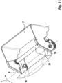
- figure 2 shows the armrest part 3 and the support structure 4 in a pushed apart or pulled apart state.
- the support structure 4 can be provided with a panel 23 which covers the free space that is formed in the support structure 4 as a result of the armrest part 3 being moved away. Due to the longitudinal mobility of the armrest part 3, the length of the armrest or the armrest arrangement 1 can be adjusted at the request of the vehicle occupant using the armrest arrangement 1.
- the armrest part 3 can, for example, be movably mounted on or on the support structure 4 between a first stop element defining a first position 11 and at least one second stop element defining a further position 12 .
- the relative longitudinal mobility of the armrest part 3 and the support structure 4 is limited by the stop elements.
- the limiting of a pushing together or the movement towards the first position 11 can be effected by the front material of the armrest part 3 since this closes off the supporting structure 4 to the front and thus forms a stop element.
- the stop element at the end of the armrest part 3 on the rotation axis side can be in contact with the support structure 4 itself or with an element rigidly connected to the support structure 4 with respect to the translation axis 10, e.g. B. the holder 7 of a support structure of the armrest part 3 occur.
- the support structure 4 can be formed, for example, from at least two support struts 15, 16 arranged at a distance from one another, in particular parallel to one another, cf. figure 3 .
- armrest part 3 is movably mounted in or on these support struts 15, 16 along a longitudinal axis 17 of the support struts 15, 16.
- the armrest part 3 can include a carriage structure 18 with at least two guide sections 19, 20, with a first guide section 19 of the carriage structure 18 being mounted in a linearly movable manner on a first support strut 15 and a further guide section 20 of the carriage structure 18 on a further support strut 16.
- the two support struts 15, 16 are arranged or formed in the area of the outer transverse ends of the armrest part 3 and thus form a stiffening structure along the longitudinal boundary of the armrest part 3.
- the carriage structure 18 can, for example, be movably mounted with the support struts 15, 16 via friction means 21 arranged or formed on the guide sections 19, 20.
- the friction means 21 can be formed as separate elements or in one piece with the guide sections 19, 20 on the carriage structure side.
- the friction means 21 form a resistance device with regard to a relative movement of the carriage structure 18 with the support struts 15, 16 and thus a force threshold value to be bridged or overridden, which must be overridden before a relative movement occurs. In other words, an unintentional movement of the armrest part 3 relative to the supporting structure 4 should be prevented by means of the friction means 21 .
- At least one friction means 21, in particular all the friction means 21 of a carriage structure 18, can be designed, for example, as an elastomer ring(s) or are designed as such. Elastomer rings can be fastened in a, in particular corresponding, receiving structure in the area of the guide sections 19, 20 in a form-fitting and/or force-fitting and/or material-locking manner.
- the at least two support struts 15, 16 can, for example, be connected at their ends assigned to the axis of rotation 6 or in the vicinity of their ends assigned to the axis of rotation 6 by means of a cross-connection means 22, in particular a cross-connection means 22 designed as a cross strut, to be connected, cf. figure 11 .
- the cross-connection means 22 can form a rigid connection of the support struts 15, 16, so that no relative movement of the first support strut 15 to the further support strut 16 is made possible due to the cross-connection means 22.
- the cross-connection means 22 can be designed, for example, as a metallic body and can be fastened to the support struts 15, 16 in a force-fitting and/or form-fitting and/or material-locking manner.
- the cross-connection means 22 is welded to the support struts 15, 16.
- the at least two support struts 15, 16 can be connected, for example, via a cross-connection means 22, in particular a cross strut, the cross-connection means 22 being at a distance from the end of the support struts 15, 16 associated with the axis of rotation 6.
- the distance between the cross-connection means 22 and the ends of the support struts 15, 16 assigned to the axis of rotation 6 can be at least 20%, preferably at least 27%, particularly preferably at least 32%, most preferably at least 35% of the total length 24 one, in particular all, support struts 15, 16 have.
- the cross-connection means 22 with these (aforementioned) minimum distances from the ends of the support struts 15, 16 can, for example, form an additional cross-connection means 22 to the cross-connection means 22 formed at the end or in the vicinity of the ends of the support struts 15, 16 pointing to the axis of rotation 6.
- the at least two support struts 15, 16 can optionally be connected via a cross-connection means 22, in particular a cross strut, with the cross-connection means 22 being at a distance (not shown) from the end of the support struts 15, 16 assigned to the axis of rotation 6, and the distance of the cross-connection means 22 from the ends of the support struts 15, 16 assigned to the axis of rotation 6 have a maximum length of 90%, preferably a maximum of 70%, particularly preferably a maximum of 55%, most preferably a maximum of 45% of the total length 24 of the support strut 15, 16.
- This cross-connection means 22 with the aforementioned maximum distances to the The ends of the support struts 15, 16 assigned to the axis of rotation 6 can, for example, represent an additional cross-connection means 22 to the cross-connection means 22, which is formed at the end or in the vicinity of the ends of the support struts 15, 16 assigned to the axis of rotation 6.
- the at least two support struts 15, 16 can be connected to one another, for example, via a first and a further cross-connection means 22, with the first cross-connection means in the vicinity of the end of the support struts 15, 16 facing the axis of rotation 6 and the further cross-connection means from the end facing the axis of rotation 6 the support struts 15, 16 are spaced apart.
- a ladder-like construction of the support structure 4 can be made possible and finally the rigidity, in particular the torsional rigidity, of the support structure can be increased.
- At least one support strut 15, 16, in particular all support struts 15, 16, can be designed as a hollow body.
- at least one support strut 15, 16, in particular all support struts 15, 16 of the support structure 4 can be designed as an, in particular, metallic, extruded profile.
- the at least one support strut 15, 16 of the support structure 4 can, for example, have an elongated cross-sectional shape 25; in particular, the longitudinal axis 26 of the cross-sectional shape 25 of the at least one support strut 15, 16, in particular all support struts 15, 16 of the support structure 4, runs when the armrest arrangement 1 is used as intended perpendicular to an armrest surface 2 of the armrest part 3.
- the padded support surface 2 is not shown, but it runs essentially parallel to that in FIG figure 3 visible surface of the closed cover element 40.
- the axis of rotation 6 can, for example, be arranged or designed in such a way that, viewed from the top view of the support structure 4, it is within a space formed by at least two cross-connecting means 22, which support struts 15, 16 of the support structure 4 connecting formed surface is arranged. In other words, the axis of rotation 6 in the plan view runs between two cross-connecting means 22 of the support structure 4.
- the support structure 4 can be rotatably mounted on a stub axle on a holder 7 of a holder structure, cf. figure 11 .
- the armrest part 3 can, for example, comprise at least one receiving device 33 , in particular defined by a recess 30 , for receiving a third object 32 .
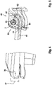
- the receiving device 33 is assigned a cover device 34, which moves in a rotational degree of freedom 35 about a cover rotation axis 36 into a first position 37, in which there is no possibility of access to a receiving space 39 defined by the at least one receiving element 31, and into at least one further position 38, in which there is a possibility of access to a receiving space 39 defined by the at least one receiving element 31, comprises a cover element 40 which is movably mounted on the armrest part 3 relative to the armrest part 3.
- the cover rotation axis 36 of the cover element 40 can, in particular exclusively, be on the half, preferably third 41, particularly preferably quarter, most preferably sixth, more preferably on the end facing away from the rotation axis 6, of the length 42 of the armrest part 3 be arranged.
- the lid rotation axis 36 can be arranged or formed, in particular exclusively, in the upper half, preferably in the upper third 43, particularly preferably in the upper quarter, most preferably in the upper fifth, of the height 44 of the armrest part 3 .
- the cover rotation axis 36 can be arranged at a front and upper end of the armrest part 3 so that when the cover element 40 pivots open, it is moved forward and, after a 180° movement, forms an extension of the armrest part 3 .
- the front end of the armrest part 3 is in this case the end of the armrest part, which of the axis of rotation 6 to perform the rotational movement 5 of the armrest part 3 is turned away.
- the free end forms the exposed end of an armrest part 3 fixed or mounted on one side, movable or immovable, on a seat and/or backrest structure or a holder 7 at the other end Armrest area of the armrest part 3 directed or pointing upwards, i.e. the area of the armrest part 3 facing the armrest support surface 2.
- the cover element 40 moved into the at least one further position 38 can, for example, be pivoted or be pivotable by an angle ⁇ , in particular from a range between 90° and 270°, preferably between 90° and 180°, relative to the first position 37.
- angle ⁇ in particular from a range between 90° and 270°, preferably between 90° and 180°, relative to the first position 37.
- the cover element 40 starting from its first, closed position 37 ( 1 ) toward its further, open position 38 by 180° (angle ⁇ ) pivoted or rotated about the axis of rotation 36 of the lid.
- the angle ⁇ for the position that widens the armrest part 3 to the maximum in the plan view, starting from the first position 37 that closes the receiving space 39, in particular to the maximum is between 160° and 200°, preferably between 170° and 190°, particularly preferably 180°.
- the cover element 40 can, for example, perform a rotational movement 46 of at least 90°, preferably of at least 135°, particularly preferably of at least 160°, most preferably of at least 175°, more preferably of at least 180°, from the first position 38 to a storage position 45 , Execute or such a minimal rotational movement 46 be executable.
- the storage position 45 is in figure 2 shown as the maximum open position of the lid member 40.
- the storage position 45 can alternatively or additionally relate to intermediate positions of the cover element 40 between the first, in particular maximally closed position 37 and the further, in particular maximally open position 38 . So e.g. B.
- Cover element 40 starting from the first position 37 figure 1 reach a storage position 45 by a rotary movement 46 through an angle ⁇ of 100° to 170°, preferably 120° to 160°.
- a third object 32 can be placed on the cover element 40 in an orientation at an angle to the armrest support surface 2 . This can be expedient if a person located next to the armrest arrangement, in particular sitting, would like to comfortably operate or use a third-party object 32 designed as a tray, which is stored in the storage position 45 of the armrest part 40 .
- the cover element 40 can rotate 46 through the angle ⁇ of a maximum of 270°, preferably a maximum of 210°, particularly preferably a maximum of 195°, most preferably a maximum of 185°, more preferably of a maximum of 180°, or such a maximum rotational movement can be carried out.
- the cover element 40 can have a maximum height 47 of no more than half, preferably no more than a third, particularly preferably no more than a quarter, most preferably no more than a fifth, of the maximum height 44 of the armrest part 3 .
- the cover element 40 can thus form a component which is narrow in comparison to the armrest part 3, so that only a small mass or a small volume is moved for the rotary movement 46 of the cover element 40.
- the impairment of the basic geometry of the armrest part 3 can be minimally influenced by the correspondingly narrow design of the cover element 40 .
- the end face of armrest part 3 located at the free end is largely unaffected by the geometry of cover element 40 and/or by the movement path of cover element 40, which is primarily defined by cover axis of rotation 36.
- a safety device 49 can be provided, which in a movement or pivoting direction into the at least one further position 38 is moved or pivoted cover element 40 in the at least one position 37, 38 against to secure further movement or pivoting in the direction of movement or pivoting.
- the safety device 49 can be designed in the manner of an end position limitation, so that further movement of the cover element 40 beyond a predefined position and/or orientation is prevented.
- the securing device 49 can be used to temporarily fix the position and/or location of the cover element 40 so that it can be fixed or maintained in predefined target alignments (a-values) or ones that can be freely selected by the operator.
- the safety device 49 is set up to block movements of the cover element 40 moved or pivoted into the at least one further position 38 in the movement or pivoting direction up to a maximum force or maximum torque limit value. After this maximum force or maximum torque limit value is exceeded, the cover element 40 can be detached from the armrest part 3 due to the safety device 49 .
- safety device 49 can be set up, for example, to prevent movements of cover element 40, which has been moved or pivoted into the at least one further position 38, in the direction of movement or pivoting when the force or torque applied to cover element 40 is above the maximum force or maximum torque limit value Release movement or pivoting of the cover element 40 in the direction of movement or pivoting without damaging or destroying the cover device 34 .
- the cover device 34 and/or the cover element 40 can also be released in such a way that, after release, it can be mounted again on the armrest part 3, in particular without tools.
- the cover element 40 can be rotatably connected to the armrest part 3, for example via a hinge section 50, with the cover element 40 being in a fully opened state of the cover element 40, in a sectional plane perpendicular to the cover rotation axis 36 of the hinge section 50, the cover element 40 on at least two contact sections 51, 52 on an armrest part side Storage structure 53 is present.
- a hinge section 50 By being within a section plane If two contact sections 51, 52 on the cover element side are perpendicular to the axis of rotation 36 of the cover element and bear against the bearing structure 53 on the armrest side (at two spaced locations), an expedient force distribution of storage forces acting on the cover element 40 in the open state can be made possible.
- the elements forming the axis of rotation themselves are powerless when the cover element 40 is in the fully open state.
- the cover element 40 can be guided in its rotational movement by a bearing means or a rotatably mounted pin, with this bearing means or this pin being actuated by the contact of the contact sections 51, 52 with these associated bearing structure contact sections, this bearing means or the pin has a reduced force-transmitting load-bearing function for the cover element 40 without force or at least partially, preferably predominantly.
- a first contact section 51 and a further contact section 52 relative to the axis of rotation 36 of the cover can, for example, form an angle ⁇ of at least 25°, preferably at least 45°, particularly preferably at least 90°, most preferably at least 110°, more preferably at least 120° , include each other.
- angle ⁇ it can be achieved that the bearing forces on the cover element side are expediently present through the contact of the armrest-side bearing structure 53 and thus high bearing forces can be reliably absorbed.
- a first contact section 51 and a further contact section 52 can, for example, form an angle ⁇ of at most 180°, preferably at most 165°, particularly preferably at most 145°, most preferably not more than 135°, more preferably not more than 130°, to one another.
- the limitation of the angle ⁇ in its maximum value can be expedient in order to limit the size and the receiving opening to be provided for nesting or moving the cover element 40 and armrest-side bearing structure into one another to an appropriate extent, but due to the minimum values of the angle ⁇ described above, a sufficient achieve high stability.
- the cover device 34 can optionally be arranged on the free end 54 or in the region of a free end 54 of the armrest part 3, with the cover element 40 moved into the at least one further position 38 forming an extension of the armrest part 3 beyond a base body of the armrest part 3 .
- the unfolded cover element 40 significantly increases the available “useful area” in the area of the upper delimitation plane of the armrest part 3 and makes this possible with a minimum of material expenditure.
- the armrest part 3 can, for example, comprise a receiving device 33 comprising at least one receiving element 31 defined by a recess 30 for a third object 32, with the receiving element 31 having at least two converging support sections 61, 62 on an upper edge 60 of the recess 30 and in a bottom and /or side wall area of the recess 30 has a contact section 65, 66.
- the receiving device 33 can include for a vehicle for receiving a third-party object 32, in particular a smartphone, comprising at least one receiving element 31 having a recess 30 for a third-party object 32.
- the receiving element 31 can have at least two converging support sections 61, 62 on an upper edge 60 of the recess 30 for storing the third object 32 and in a bottom and/or side wall region 63, 64 of the recess 30 a contact section 65, 66 for storing the third object 32 exhibit.
- the third-party object has an elongate cuboid or cuboid basic shape.
- the basic shape means that the third-party item can also have edges and/or corners that are "cut off” or rounded off or otherwise deviate from a strictly cuboid shape. Rather, a cuboid basic shape means that it essentially has six opposite parallel surfaces in pairs, the short side having at least half, preferably at least a quarter, particularly preferably at least an eighth, most preferably at least a fifteenth of the length of the long side.
- the third-party object 32 can be based on typical basic forms of mobile phones, in particular smartphones, cf. figures 8 and 9 .
- the receiving device 33 can, for example, be fastened or accommodated in or on a vehicle interior component; in particular, the receiving device 33 is part of an armrest part 3 of a vehicle, cf. figure 2 . Alternatively or in addition to an armrest 3 in the rear of the vehicle, the receiving device 33 can be arranged or formed on a door side panel and/or on a bench seat and/or on a dashboard and/or on a vehicle column panel and/or on a front center console.
- At least one support section 61, 62 in particular all of the support sections 61, 62, can be designed as an edge, for example.
- the edge-like design of the at least one support section 61, 62 can result in a point contact point between the support section 61, 62 and the third object 32 in the event of contact with the third object 32, in particular with a boundary edge of the third object 32.
- a selective point of contact or a small contact area between the third object 32 and the converging support sections 61, 62 can be advantageous in that a centering and/or guiding function for aligning the third object 32, in particular due to gravity, is simplified and/or can be carried out or is carried out with little frictional influence.
- the additional or alternative configuration of the at least one contact section as a contact surface 67, 68 can enable or support a simplified intended insertion and/or alignment of the third-party object 32.
- the contact section 65, 66 can optionally have at least two contact surfaces 67, 68, with a main extension plane 69 of an at least partially, preferably predominantly, particularly preferably completely, flat first contact surface 67 with the main extension plane 70 of a further, at least partially, preferably predominantly, particularly enclose an angle ⁇ of less than 90°, preferably less than 80°, particularly preferably less than 75°, most preferably less than 70°.
- the two contact surfaces 67 in particular a first, preferably flat, contact surface 67 forming the base and a further, preferably flat, contact surface 68, in particular forming a side wall of the recess 30, enclose an angle ⁇ of less than 90°, it is possible in a simple manner a self-centering insertion movement, in particular caused by gravity, of the third object 32 can be achieved.
- This increases the area of performance of the receiving device 33 such that, in the case of a defined receiving situation for the third-party object 32, geometric measures for holding the third-party object 32 can be reliably maintained despite any cornering forces when the vehicle having the receiving device 33 is cornering.
- Contact section 65 can have, for example, at least one floor contact surface 67, with a main extension plane 69 of floor contact surface 67, which is planar at least in sections, preferably predominantly, particularly preferably completely, having an angle ⁇ of with a basic extension plane 71 of receiving device 33 or a horizontal plane when receiving device 33 is used as intended greater than 5°, preferred greater than 10°, more preferably greater than 15°, most preferably greater than 17.5°, more preferably greater than 20°.
- the horizontal plane or the basic extension plane 71 allows the ground contact surface 67 to be classified in terms of gravity, since the basic extension plane 71 is aligned parallel to the arm support surface 2 of the armrest part 3 when the receiving device 33 is located in or on an armrest part 3.
- the receiving element 31 that defines the depression 30 can have an n-cornered basic shape, for example, in a top view; In this case, the plan view can be aligned perpendicular to the main extension plane or to the basic extension plane 71 of the receiving device 33 .
- the receiving element 31 that defines the recess 30 can have a base edge 73 of a basic shape that is provided with an interruption 72 and is in particular rectilinear in plan view.
- the interruption 72 can be used, for example, to lay and/or move a charging cable or the like from a first area of a recess 30 in the receiving device 31 to a further area of this or a further recess 30 in the receiving device 31, without the charging cable breaking through Has to leave recess 30 or without the charging cable having to be led out of the main extension volume of the receiving device 31 .
- At least one bearing section 61, 62 designed as a bearing edge can, for example, in its main extension line 74, 75, in particular both bearing edges with their main extension lines 74, 75, with the bearing section 61 designed as a base edge 73, in a top view, form an interior angle ⁇ to the interior 76 of the depression 30 from less than 90°, preferably less than 85°, particularly preferably less than 80°, most preferably less than 75°.
- the two main extension lines 74, 75 of the support sections 61, 62 have an angle ⁇ in range from 20° to 50°, preferably from 25° to 40°, particularly preferably from 30° to 35°.
- the bearing sections 61, 62 in particular the bearing sections 61, 62 designed as bearing edges, can be designed, for example, with mirror symmetry.
- the support sections 61, 62, in particular the support edges, are preferably formed mirror-symmetrically to a longitudinal axis 77 of the insert 78 and/or the receiving device 33.
- the mirror-symmetrical design of the support sections 61, 62 enables the receiving device to be used more easily, since a similar structure for introducing the third-party object 32 is made possible, regardless of the location of an operator.
- the receiving device 33 can have, for example, a base body 79 having at least one recess 30 and an insert body (not shown) of corresponding geometry which is arranged or formed in the recess 30 on the base body side and forms the at least one receiving element 31 .
- the base body 79 can be provided at least in sections, preferably predominantly, particularly preferably completely, with an insert body designed as a cover and/or as a coating. In this way, the surface of the base body 79 facing the interior of the recess 30 is at least partially covered with the material of the insert body. Consequently, the insert body can serve as a direct contact body for contacting the third object 32 .
- the radii 81 or angles defining the depression 30 in the base body 79 can be formed smaller than the radii or angles defining the depression 30 in the insert body. Consequently, the base body 79 can be produced, for example, by an injection molding process and have relatively small radii 81 at least in sections, but the minimum size of the accessible radii of the receiving device is defined or determined by the insert body sections covering the base body-side radii 81 towards the interior and its comparatively larger radii.
- the receiving device in particular the insert body, can be formed, for example, at least in sections, preferably predominantly, particularly preferably completely, from a soft-elastic plastic material, in particular a thermoplastic elastomer.
- the receiving device 33 can have, for example, a plurality of receiving elements 31 of different basic shapes, at least in sections, optionally completely.
- the receiving device 33 can comprise three different receiving elements 31 .
- the receiving element 31 shown on the left can be used to hold a smartphone in an inclined position
- the receiving element 31 shown in the middle can be used to hold a smartphone in an upright position
- the right-hand receiving element 31 can be used to hold a liquid container, in particular a beverage container.
- center of gravity 48 of the third object 32 is indicated, it can be seen from this that this lies within the basic shape of the depression 30 or the border delimiting the depression 30 in the plan view. According to figure 10 it can be provided that the center of gravity 48 of the third object 32 lies within the depression 30 and/or is placed in the vicinity of the boundary edge of the depression 30 when the receiving device 33 is used as intended, ie when the third object 32 is inserted into the depression 30, cf. figure 10 .
- the depression 30 or the receptacle of the receiving device 31 with the edges 61, 62 running towards one another has a maximum depth of a maximum of 80 mm, preferably a maximum of 70 mm, particularly preferably a maximum of 60 mm, most preferably a maximum of 50 mm , further preferably of a maximum of 45 mm.
- This maximum depth can relate, for example, to the depth which actually or potentially forms the deepest point for supporting the third-party object 32 when the receiving device 31 is used as intended.
- the deepest point is formed as the intersection of the longest contact section 66 or the side wall 66 and the bottom of the depression 30, which in particular runs obliquely downwards.
- the maximum depth of the depression 30 or the maximum depth of the receptacle of the depression 30 can, for example, especially when viewed from above, to the first and/or second length 85, 87 have a ratio of at most 1.0, preferably at most 0.85 , particularly preferably not more than 0.70, most preferably not more than 0.60, more preferably not more than 0.55.
- the depression 30 thus has a rather shallow depth compared to its length 85, 87, in particular in the longitudinal and/or transverse direction relative to a desired orientation of an elongate third object 32 within the receiving device 33 or the receiving element 31.
- the recess 30 has a polygonal basic shape in plan view.
- the receptacle or the depression 30 of the receptacle element 31 can be designed in such a way that this one, in particular when viewed from above—cf. figure 7 -, first length 85 and/or a second length 87 in the range from 60 mm to 100 mm, preferably from 70 mm to 90 mm, particularly preferably from 75 mm to 85 mm.
- the first length 85 can be aligned, for example, parallel to a longitudinal axis 77 of a receiving device 33, in particular a receiving device 33 designed as an insert 78.
- the first and second lengths 85, 87 may be perpendicular to one another.
- the first length 85 faces the second length 87 has a ratio of from 0.80 to 1.00, preferably from 0.85 to 0.99, particularly preferably from 0.90 to 0.98, most preferably from 0.95 to 0.97.
- the geometry of the depression 30 or of the receptacle of the receptacle element 31 can essentially have a trapezoidal section when viewed from above.
- This trapezoidal section is characterized by the two edges 61, 62 of the recess 30 and the receptacle that converge.
- the maximum distance can correspond to the second 87 mentioned above or to the value ranges mentioned for this purpose.
- the minimum distance 88 between the two edges 61, 62 running towards one another can correspond, for example, to 40 mm to 80 mm, preferably 50 mm to 70 mm, particularly preferably 57 mm to 67 mm, most preferably 60 mm to 64 mm.
- the length perpendicular to the maximum and/or minimum distance 88 of at least one, in particular both, converging edge(s) can, for example, be between 20 mm and 50 mm, preferably between 30 mm and 40 mm, particularly preferably between 33 mm and 38 mm.
- a further advantage with regard to the lengths, angles and their ratios of the receiving device 33 or their recess 30 described here can be seen in the fact that in the case of a third-party object 32 designed as a smartphone, its loudspeakers arranged on the back and/or underside of the third-party object produce good sound can bring out.
- the sloping floor can serve as a reflection surface in order to deflect the sound upwards to the opening of the depression 30 and thus to a vehicle occupant.
- the third object 32 in the intended target position in the depression 30 has an air gap at the theoretical point of intersection of the converging edges 61, 62, which allows for the propagation of sound reflected on the side walls and the, in particular sloping, bottom of the depression 30 upwards or downwards , outside of the recess 30 can contribute.
- the trapezoidal section is followed by a substantially rectangular section, with both sections forming part of the depression.
- the length of both subsections can, for example, correspond to the first length 85 and have the values mentioned above for the first length 85 .
- the rectangular section as part of the length 85 can have a length 86 of 25 mm to 65 mm, preferably 35 mm to 55 mm, particularly preferably 40 mm to 50 mm, most preferably 43 mm to 47 mm.
- the explicit areas mentioned in the previous paragraphs for the dimensioning of the depression 30 or for the receptacle for receiving the third-party object 32 and/or the ratios of individual geometric variables of the depression 30 that can be derived therefrom enable a third-party object 32 with dimensions typical of smartphones to be advantageously held.
- the specified dimensions, in particular in combination with a sloping bottom area of the depression 30, reflect an advantageous - because centering and / or guiding function and at the same time an advantageous alignment of a third object 32 in the end position or in the rest position, in particular a smartphone.
- Both the insertion and the removal of the third-party object 32, in particular a smartphone can be carried out in a simplified manner for a person due to its oblique arrangement within the receiving device 33.
- the operability is also simplified for an operator due to the inclined position, since a certain free space in front of the third-party object 32 can also be reserved within the depression 30, which can be used for manual operation of input elements of the third-party object 32 arranged there, e.g. B. a home button of a third-party object designed as a smartphone 32.
- the receiving device 33 can be assigned at least one, in particular socket-type or plug-type, connection element 83 for connecting a charging and/or data transmission element 84 .
- connection element 83 for connecting a charging and/or data transmission element 84 .
Landscapes
- Engineering & Computer Science (AREA)
- Mechanical Engineering (AREA)
- Seats For Vehicles (AREA)
Abstract
Aufnahmeeinrichtung (33) für ein Fahrzeug zur Aufnahme eines Drittgegenstands (32), insbesondere eines Smartphones, umfassend wenigstens ein eine Vertiefung (30) aufweisendes Aufnahmeelement (31) für einen Drittgegenstand (32), wobei das Aufnahmeelement (31) an einem oberen Rand (60) der Vertiefung (30) wenigstens zwei, insbesondere einander zulaufende, Auflageabschnitte (61, 62) zur Lagerung des Drittgegenstands (32) und in einem Boden- und/oder Seitenwandbereich (63, 64) der Vertiefung (30) einen Anlageabschnitt (65, 66) zur Lagerung des Drittgegenstands (32) aufweist.Receiving device (33) for a vehicle for receiving a third-party object (32), in particular a smartphone, comprising at least one receiving element (31) having a recess (30) for a third-party object (32), the receiving element (31) having an upper edge ( 60) of the recess (30) at least two, in particular converging, support sections (61, 62) for storing the third object (32) and in a bottom and/or side wall area (63, 64) of the recess (30) a contact section (65 , 66) for storing the third-party object (32).
Description
Die Erfindung betrifft eine Aufnahmeeinrichtung für ein Fahrzeug zur Aufnahme eines Drittgegenstands.The invention relates to a receiving device for a vehicle for receiving a third-party object.
Entsprechende Aufnahmeeinrichtungen für Fahrzeuge zur Aufnahme eines Drittgegenstands sind aus dem Stand der Technik dem Grunde nach bekannt. So ist es beispielsweise bekannt, im Fond von Automobilen Aufnahmeeinrichtungen zu verbauen. Derartige Aufnahmeeinrichtungen können als Getränkehalter und/oder Handyhalter ausgebildet sein.Corresponding receiving devices for vehicles for receiving a third-party object are basically known from the prior art. For example, it is known to install recording devices in the rear of automobiles. Such receiving devices can be embodied as cup holders and/or mobile phone holders.
Der Erfindung liegt die Aufgabe zugrunde, eine Aufnahmeeinrichtung anzugeben, welche insbesondere im Hinblick auf eine einfache sowie kostengünstige Maßnahme den Bedienkomfort und die Nutzungsmöglichkeiten erhöht.The invention is based on the object of specifying a recording device which, in particular with regard to a simple and cost-effective measure, increases the ease of use and the possible uses.
Die Aufgabe wird durch eine Aufnahmeeinrichtung zum Verbau in einem Fond eines Kraftfahrzeugs gemäß Anspruch 1 gelöst. Die hierzu abhängigen Ansprüche betreffen mögliche Ausführungsformen der Aufnahmeeinrichtung.The object is achieved by a receiving device for installation in a rear of a motor vehicle according to claim 1. The dependent claims relate to possible embodiments of the receiving device.
Die Erfindung betrifft eine Aufnahmeeinrichtung mit wenigstens einem durch eine Vertiefung definiertes Aufnahmeelement für einen Drittgegenstand, wobei das Aufnahmeelement an einem oberen Rand der Vertiefung zwei, insbesondere zumindest abschnittsweise, bevorzugt überwiegend, besonders bevorzugt vollständig, einander zulaufende, Auflageabschnitte zur Lagerung des Drittgegenstands und in einem Boden- und/oder Seitenwandbereich der Vertiefung einen Anlageabschnitt zur Lagerung des Drittgegenstands aufweist. Durch das Aufnahmeelement der Aufnahmeeinrichtung kann beispielsweise wenigstens ein Drittgegenstand in die Vertiefung eingelegt und/oder aufgelegt werden. Damit kann die Aufnahmeeinrichtung eine Aufbewahrungsfunktion erfüllen, sodass ein Drittgegenstand, z. B. ein Smartphone oder ein sonstiger länglicher, insbesondere quaderförmiger, Körper gekippt in das Aufnahmeelement eingesetzt werden kann. Durch die gekippte Positionierung des Drittgegenstands liegt dieser an zwei Auflageabschnitten, insbesondere an zwei Auflagekanten, an dem oberen Ende bzw. dem oberen Rand des Aufnahmeelements und zusätzlich an dem Anlageabschnitt des Aufnahmeelements an. Hierbei befindet sich der Anlageabschnitt in einem Boden- und/oder Seitenwandbereich der Vertiefung des Aufnahmeelements.The invention relates to a receiving device with at least one receiving element, defined by a recess, for a third object, the receiving element on an upper edge of the recess having two support sections, in particular at least in sections, preferably predominantly, particularly preferably completely, converging on each other for storing the third object and in one Bottom and / or side wall area of the depression has a contact section for storing the third-party object. At least one third-party object, for example, can be inserted and/or placed in the recess by the receiving element of the receiving device. The receiving device can thus fulfill a storage function, so that a third-party object, e.g. B. a smartphone or another elongated, in particular cuboid, body tilted into the Recording element can be used. Due to the tilted positioning of the third object, it rests against two supporting sections, in particular against two supporting edges, against the upper end or the upper edge of the receiving element and additionally against the contact section of the receiving element. In this case, the contact section is located in a bottom and/or side wall area of the recess of the receiving element.
Nachfolgend wird beispielhaft die Aufnahmeeinrichtung als eine in oder an einer Armlehne angeordnete oder ausgebildete Aufnahmeeinrichtung beschrieben, hierbei kann die Armlehne in einem Fahrzeugfond oder an einem anderen Ort des Fahrzeugs angeordnet oder ausgebildet sein. Auch ist es möglich die hierin beschriebene Aufnahmeeinrichtung unabhängig (a) zu einem Verbau in oder an einer Armlehne oder (b) zu einem Verbau in oder an einem Fahrzeug einzusetzen.The receiving device is described below by way of example as a receiving device arranged or formed in or on an armrest; the armrest can be arranged or formed in a vehicle rear or at another location of the vehicle. It is also possible to use the receiving device described herein independently (a) for installation in or on an armrest or (b) for installation in or on a vehicle.
Durch die insgesamt wenigstens drei Abschnitte und damit wenigstens drei Kontaktbereiche des Drittgegenstands mit der Aufnahmeeinrichtung, kann der Drittgegenstand bewegungsgesichert in der Vertiefung der Aufnahmeeinrichtung gelagert bzw. aufgenommen werden.Due to the total of at least three sections and thus at least three contact areas of the third-party object with the receiving device, the third-party object can be stored or received in the depression of the receiving device in a manner secured against movement.
Es ist möglich, dass wenigstens ein Auflageabschnitt, insbesondere sämtliche Auflageabschnitte, als Kante ausgebildet ist bzw. sind und/oder der Anlageabschnitt als zumindest eine Anlagefläche ausgebildet ist. Die Anlagefläche kann dazu dienen den, eine ebene Fläche aufweisenden Drittgegenstand punktuell oder linienartig zu berühren. An den Auflagekanten des Auflageabschnitts kann der Drittgegenstand jeweils einen punktförmigen Kontaktabschnitt aufweisen, folglich kann im Falle zweier einander zulaufender Auflagekanten der Drittgegenstand an jeder dieser Auflagekanten einen Berührpunkt aufweisen und durch die zulaufende Ausrichtung der Auflagekanten eine Zwangsführung zu einem Zentrierposition erwirken. Damit kann der flächige und/oder der eine längliche quadergrundform aufweisende Drittgegenstand über jeweils einen punktuellen Kontaktpunkte mit der ersten und der weiteren Auflagekante und über einen linienförmigen Kontaktabschnitt oder über zumindest zwei, insbesondere über exakt zwei, punktuelle Kontaktabschnitte in dem Aufnahmeelement aufgenommen bzw. abgestützt sein.It is possible that at least one support section, in particular all of the support sections, is/are designed as an edge and/or the contact section is designed as at least one contact surface. The contact surface can serve to touch the third object, which has a flat surface, in a point or line-like manner. The third object can have a punctiform contact section on each of the contact edges of the contact section. Consequently, in the case of two contact edges that converge, the third object can have a contact point on each of these contact edges and the converging alignment of the contact edges can result in forced guidance to a centering position. In this way, the flat third-party object and/or the third-party object, which has an elongated cuboid basic shape, can contact the first and the further contact edge via a punctiform contact point and via a linear contact section or via at least two, in particular exactly two, punctiform contact sections can be accommodated or supported in the receiving element.
Durch die zwei einander zulaufenden Auflagekanten an der Oberseite der Vertiefung können unterschiedliche Drittgegenstände definiert aufgenommen werden. Breitere Drittgegenstände nehmen dabei eine steilere bzw. näher an der Vertikalen liege Position als schmalere Drittgegenstände.Due to the two converging support edges on the upper side of the recess, different third-party objects can be accommodated in a defined manner. Broader third objects assume a steeper or closer to the vertical position than narrower third objects.
Der Anlageabschnitt kann beispielsweise wenigstens zwei Anlageflächen aufweisen, wobei eine Haupterstreckungsebene einer zumindest abschnittsweisen, bevorzugt überwiegenden, besonders bevorzugt vollständig, ebenen ersten Anlagefläche mit der Haupterstreckungsebene einer weiteren, zumindest abschnittsweise, bevorzugt überwiegend, besonders bevorzugt vollständig, eben ausgebildeten weiteren Anlagefläche einen Winkel γ von kleiner 90°, bevorzugt kleiner 80°, besonders bevorzugt kleiner 75°, höchst bevorzugt kleiner 70°, einschließt. Dadurch, dass der Winkel zwischen der ersten und zweiten Anlagefläche kleiner 90° ist, kann aufgrund eines Rutschens eines Drittgegenstands eine Führungsfunktion bzw. eine Zentrierfunktion auf den Drittgegenstand erwirkt werden, welche dazu genutzt werden kann, den Drittgegenstand in eine vordefinierte Position und/oder Ausrichtung, insbesondere eine vordefinierte Schräglage, relativ zu dem Aufnahmeelement zu verbringen. Mit anderen Worten kann der Boden des Aufnahmeelements bzw. der Vertiefung zu wenigstens einer, insbesondere abschnittsweise ebenen, Seitenwand schräg verlaufen, sodass ein in das Aufnahmeelement eingesetzter Drittgegenstand aufgrund der Schwerkraft und der Schräglage des Bodens zu dem tieferliegenden Bereich des Aufnahmeelements bewegt wird.The contact section can have at least two contact surfaces, for example, with a main extension plane of an at least partially, preferably predominantly, particularly preferably completely, flat first contact surface forming an angle γ with the main extension plane of a further, at least partially, preferably predominantly, particularly preferably completely, flat further contact surface less than 90°, preferably less than 80°, particularly preferably less than 75°, most preferably less than 70°. Due to the fact that the angle between the first and second contact surface is less than 90°, a guiding function or a centering function can be effected on the third object due to a slipping of a third object, which can be used to move the third object into a predefined position and/or alignment , To spend in particular a predefined inclined position relative to the receiving element. In other words, the bottom of the receiving element or the depression can run obliquely to at least one side wall, in particular that is flat in sections, so that a third-party object inserted into the receiving element is moved to the lower-lying area of the receiving element due to gravity and the inclined position of the bottom.
In einer optionalen Ausführungsform kann es vorgesehen sein, dass der Anlageabschnitt wenigstens eine Bodenanlagefläche aufweist, wobei eine Haupterstreckungsebene der zumindest abschnittsweisen, bevorzugt überwiegenden, besonders bevorzugt vollständig, ebenen Bodenanlagefläche mit einer Grunderstreckungsebene der Armlehnenanordnung oder einer Horizontalebene im bestimmungsgemäßen Einsatz der Armlehnenanordnung einen Winkel δ von größer 5°, bevorzugt von größer 10°, besonders bevorzugt von größer 15°, höchst bevorzugt von größer 17,5°, weiter bevorzugt von größer 20°, einschließt. Auch diese Schräglage der Bodenanlagefläche relativ zur Horizontalebene im bestimmungsgemäßen Einsatz des Aufnahmeelements führt zu einer, ggf. weitergehenden, gezielten Verlagerung eines in das Aufnahmeelement aufgenommenen Drittgegenstands.In an optional embodiment, it can be provided that the contact section has at least one floor contact surface, with a main extension plane of the at least partially, preferably predominantly, particularly preferably completely, flat floor contact surface having a basic extension plane of the armrest arrangement or a horizontal plane when the armrest arrangement is used as intended includes an angle δ of greater than 5°, preferably greater than 10°, particularly preferably greater than 15°, most preferably greater than 17.5°, more preferably greater than 20°. This inclined position of the ground contact surface relative to the horizontal plane when the receiving element is used as intended also leads to a possibly more extensive, targeted displacement of a third-party object received in the receiving element.
Das die Vertiefung definierende Aufnahmeelement kann beispielsweise in der Draufsicht eine n-eckige Grundform aufweisen, bevorzugt weist das Aufnahmeelement eine mindestens 5-eckige Grundform auf, besonders bevorzugt weist das Aufnahmeelement eine mindestens 6-eckige Grundform auf. Die Grundform des Aufnahmeelement kann beispielsweise punkt- und/oder spiegelsymmetrisch ausgebildet sein. In einer optionalen Ausführungsform weist die Grundform eine spiegelsymmetrische, aber nicht punktsymmetrische Grundform auf. Bevorzugt verläuft die Spiegelachse der spiegelsymmetrischen Grundform des Aufnahmeelement in der Draufsicht aus betrachtet parallel oder rechtwinklig zu einer Längsachse der Aufnahmeeinrichtung, insbesondere parallel oder rechtwinklig zu einer Längsachse einer die Aufnahmeeinrichtung umfassenden Armlehnenanordnung oder eines Armlehnenteils der Armlehnenanordnung.The receiving element that defines the depression can have an n-cornered basic shape, for example, in a top view; the receiving element preferably has an at least pentagonal basic shape, particularly preferably the receiving element has an at least 6-cornered basic shape. The basic shape of the receiving element can be point-symmetrical and/or mirror-symmetrical, for example. In an optional embodiment, the basic shape has a mirror-symmetrical but not point-symmetrical basic shape. The mirror axis of the mirror-symmetrical basic shape of the receiving element, viewed in plan, preferably runs parallel or at right angles to a longitudinal axis of the receiving device, in particular parallel or at right angles to a longitudinal axis of an armrest arrangement comprising the receiving device or an armrest part of the armrest arrangement.
Das die Vertiefung definierende Aufnahmeelement kann beispielsweise in der Draufsicht eine mit einer Unterbrechung versehene, insbesondere geradlinige, Grundkante einer Grundform und/oder, insbesondere ebene, Seitenwandfläche aufweisen. Die Unterbrechung kann zur Aufnahme eines Abschnitts eines Ladekabels zum Anschluss des Ladekabels an einem Drittgegenstand während dessen Aufnahme in dem Aufnahmeelement vorgesehen sein. Hierbei kann es vorgesehen sein, das die wenigstens zwei Auflageabschnitte, insbesondere die wenigstens zwei Auflagekanten, der Grundkante gegenüberliegen angeordnet oder ausgebildet sind.The receiving element that defines the depression can have, for example, a base edge of a basic shape that is provided with an interruption, in particular a straight line, and/or, in particular, a flat side wall surface, when viewed from above. The interruption can be provided for accommodating a section of a charging cable for connecting the charging cable to a third-party object while it is being accommodated in the accommodating element. It can be provided here that the at least two support sections, in particular the at least two support edges, are arranged or formed opposite the base edge.
Wenigstens ein als Auflagekante ausgebildeter Auflageabschnitt kann beispielsweise in seiner Haupterstreckungslinie, insbesondere beide Auflagekanten jeweils mit deren Haupterstreckungslinien, mit dem als Grundkante ausgebildeten Anlageabschnitt in der Draufsicht einen zum Innenraum der Vertiefung zugewandten Innenwinkel ε im Bereich von kleiner 90°, bevorzugt von kleiner 85°, besonders bevorzugt von kleiner 80°, höchst bevorzugt von kleiner 75°, aufweisen. Der Innenwinkel ε kann beispielsweise mindestens 30°, bevorzugt mindestens 45°, besonders bevorzugt mindestens 55°, höchst bevorzugt mindestens 65°, weiter bevorzugt mindestens 70°, einschließen. Dadurch, dass wenigstens eine Auflagekante, insbesondere beide oder sämtliche Auflagekanten, einen spitzen Winkel ε zur Grundkante des Aufnahmeelements aufweist bzw. aufweisen, kann erreicht werden, dass ein an einer flächigen, die Grundkante umfassenden Wand angelegter länglicher quaderförmiger Drittgegenstand bei dessen Einlegen in die Vertiefung des Aufnahmeelements schwerkraftbedingt zu einem Zielort bzw. Bestimmungsort geführt wird bzw. sich dorthin begibt. Mit anderen Worten können die beiden Auflagekanten derart spitzwinklig (vgl. Winkel ζ) zueinander ausgerichtet sein, dass ein an beiden Auflagekanten anliegender länglicher quaderförmiger Drittgegenstand sich in eine zu dem fiktiven Treffpunkt der beiden Auflagekanten hin gerichtete Zwangsposition begibt. Durch das Erreichen der zwangsgeführten Sollposition aufgrund der entsprechend zueinander ausgerichteten Auflagekanten, kann auf eine definierte Ausrichtung und Positionierung des Drittgegenstands innerhalb des Aufnahmeelements erreicht werden, zumindest weitgehend unabhängig von der Positionierung und/oder Ausrichtung des Drittgegenstands bei dessen einlegen in die Vertiefung des Aufnahmeelements.At least one support section designed as a support edge can, for example, in its main extension line, in particular both Support edges each with their main extension lines, with the contact section designed as a base edge in plan view an interior angle ε facing the interior of the depression in the range of less than 90°, preferably less than 85°, particularly preferably less than 80°, most preferably less than 75°, exhibit. The internal angle ε can include, for example, at least 30°, preferably at least 45°, particularly preferably at least 55°, most preferably at least 65°, more preferably at least 70°. Because at least one support edge, in particular both or all of the support edges, has or have an acute angle ε to the base edge of the receiving element, it can be achieved that an elongate cuboid third-party object placed against a flat wall surrounding the base edge when it is placed in the recess of the receiving element is guided to a destination or place of destination due to the force of gravity or goes there. In other words, the two bearing edges can be aligned at such an acute angle (cf. angle ζ) to one another that an elongate cuboid third object resting on both bearing edges moves into a constrained position directed towards the imaginary meeting point of the two bearing edges. By reaching the forcibly guided target position due to the correspondingly aligned support edges, a defined orientation and positioning of the third-party object within the receiving element can be achieved, at least largely independently of the positioning and/or orientation of the third-party object when it is placed in the recess of the receiving element.
Die Auflageabschnitte, insbesondere die als Auflagekanten ausgebildeten Auflageabschnitte, können beispielsweise zumindest abschnittsweise, bevorzugt überwiegend, besonders bevorzugt gänzlich, spiegelsymmetrisch ausgebildet sein. Bevorzugt sind die Auflageabschnitte, insbesondere die Auflagekanten, spiegelsymmetrisch zu einer Längsachse der Aufnahmeeinrichtung und/oder zu einer Längsachse eines die Aufnahmeeinrichtung umfassenden Armlehnenteils ausgerichtet. Hierbei können die Auflagekanten eine nicht punktsymmetrische Form bzw. eine zumindest abschnittsweise geradlinige Form aufweisen.The bearing sections, in particular the bearing sections designed as bearing edges, can be mirror-symmetrical, for example, at least in sections, preferably predominantly, particularly preferably entirely. The support sections, in particular the support edges, are preferably aligned mirror-symmetrically to a longitudinal axis of the receiving device and/or to a longitudinal axis of an armrest part comprising the receiving device. In this case, the bearing edges can have a non-point-symmetrical shape or a straight shape, at least in sections.
Die Aufnahmeeinrichtung kann beispielsweise einen wenigstens eine Vertiefung aufweisenden Grundkörper und einen in der grundkörperseitigen Vertiefung angeordneten oder ausgebildeten, das wenigstens eine Aufnahmeelement bildenden Einsatzkörper korrespondierender Geometrie aufweisen. Mit anderen Worten kann das Aufnahmeelement in eine Vertiefung der Aufnahmeeinrichtung eingesetzt werden, wobei das Aufnahmeelement als Einsatzkörper in eine zu diesem eine korrespondierende Geometrie aufweisende Öffnung eingesetzt werden kann bzw. eingesetzt wird.The receiving device can have, for example, a base body having at least one depression and an insert body of corresponding geometry, which is arranged or formed in the depression on the base body side and forms the at least one receiving element. In other words, the receiving element can be inserted into a recess of the receiving device, wherein the receiving element as an insert body can be or is inserted into an opening having a corresponding geometry.
Die die Vertiefung in dem Gehäusekörper definierenden Winkel können beispielsweise kleiner als die die Vertiefung in dem Einsatzkörper definierenden Winkel ausgebildet sein. Die die Vertiefung in dem Gehäusekörper definierenden Radien bzw. Winkel sind - dies gilt insbesondere für die den Öffnungsbereich der Vertiefung bildenden Radien bzw. Winkel - beispielsweise in einem Bereich oberhalb von 2,5 mm, bevorzugt von oberhalb 3,5 mm. Die die Vertiefung in dem Einsatzkörper definierenden Radien bzw. Winkel sind - dies gilt insbesondere für die den Öffnungsbereich der Vertiefung bildenden Radien bzw. Winkel - beispielsweise oberhalb 2,5 mm, bevorzugt von oberhalb 3,5 mm.The angles defining the indentation in the housing body can, for example, be made smaller than the angles defining the indentation in the insert body. The radii or angles defining the depression in the housing body are—this applies in particular to the radii or angles forming the opening area of the depression—for example in a range above 2.5 mm, preferably above 3.5 mm. The radii or angles defining the depression in the insert body are—this applies in particular to the radii or angles forming the opening region of the depression—for example above 2.5 mm, preferably above 3.5 mm.
Der Einsatzkörper kann beispielsweise aus einem weich-elastischen Kunststoffmaterial, insbesondere einem thermoplastischen Elastomer, ausgebildet sein.The insert body can be made, for example, from a soft, elastic plastic material, in particular a thermoplastic elastomer.
Die Aufnahmeeinrichtung kann beispielsweise mehrere Aufnahmeelemente zumindest abschnittsweise, gegebenenfalls vollständig, unterschiedlicher Grundform aufweisen. So kann die Aufnahmeeinrichtung mehrere jeweils eine Vertiefung ausbildende Aufnahmeelemente umfassen, wobei die jeweiligen Aufnahmeelemente ein einstückiges bzw. integrales Bauteil ausbilden können oder als separate, zusammengebaute und/oder mittelbar oder unmittelbar miteinander befestigte Bauteile ausbilden.The receiving device can, for example, have a plurality of receiving elements, at least in sections, possibly completely, of different basic shapes. The receiving device can thus comprise a plurality of receiving elements each forming a depression, with the respective receiving elements being able to form a one-piece or integral component or as separate, assembled components and/or components fastened directly or indirectly to one another.
Der Aufnahmeeinrichtung kann beispielsweise wenigstens ein, insbesondere buchsen- oder steckerartiges, Anschlusselement zum Anschluss eines Lade- und/oder Datenübertragungselements zugeordnet sein. Damit kann es ermöglicht werden, einen in dem Aufnahmeelement aufgenommenen Drittgegenstand, z. B. ein Smartphone, im in dem Aufnahmeelement aufgenommenen Zustand vermittels eines Datenübertragungselements, z. B. eines Ladekabels, das in dem Anschlusselement der Aufnahmeeinrichtung, insbesondere elektrisch, zu verbinden bzw. stromleitend und/oder datenübertragend zu verbinden. In diesem Zusammenhang ist die zentrierende bzw. zwangsführende und insbesondere schwerkraftbedingt erfolgende Positionierung und/oder Ausrichtung des Drittgegenstands aufgrund des schrägen Bodens und/oder der einander zulaufenden Auflagekanten vorteilhaft, da bevorzugt die vordefinierte Soll- bzw. Zwangspositionierung und/oder Ausrichtung des Drittgegenstands, dessen Verbindbarkeit bzw. dessen Anschluss mit den Datenübertragungselement erleichtert.For example, at least one, in particular socket-type or plug-type, connection element for connecting a charging and/or data transmission element can be assigned to the receiving device. This can make it possible to hold a third-party object, e.g. B. a smartphone, in the recorded state in the receiving element by means of a data transmission element, z. B. a charging cable, in the connection element of the receiving device, in particular to connect electrically or to connect current-carrying and / or data-transmitting. In this context, the centering or constrained positioning and/or alignment of the third-party object, in particular due to the force of gravity, is advantageous due to the sloping base and/or the converging support edges, since the predefined target or forced positioning and/or alignment of the third-party object, its Connectivity or its connection facilitated with the data transmission element.
Die Aufnahmeeinrichtung kann beispielsweise wenigstens ein Aufnahmeelement aufweisen, das in der Draufsicht aus betrachtet zwei einander zulaufende, insbesondere geradlinige, Auflagebereiche bzw. Auflagekanten umfasst. Hierbei können die Auflagekanten einen horizontalen Mindestabstand von mindestens 40 mm, bevorzugt von mindestens 50 mm, besonders bevorzugt von mindestens 55 mm, höchst bevorzugt von mindestens 60 mm, aufweisen. Der horizontale Maximalabstand der beiden Auflagekanten kann beispielsweise maximal 150 mm, bevorzugt maximal 120 mm, besonders bevorzugt maximal 100 mm, höchst bevorzugt maximal 90 mm, weiter bevorzugt maximal 85 mm, aufweisen. Insbesondere dann, wenn die Auflagekanten im Bereich der genannten horizontalen Mindestabstände und zugleich im Bereich der genannten Maximalabstände liegt, kann eine vorteilhafte Geometrie erreicht werden, welche bei Einlegen eines Smartphones sowohl dessen schwerkraftbedingte Zentrierung bzw. Zwangsführung und zugleich nach Erreichen der Soll- bzw. Zwangsposition ein zuverlässiges Halten des Smartphones innerhalb des Aufnahmeelements ermöglicht. Mit einem horizontalen Maximal- oder Minimalabstand ist hierbei der Abstand der Auflagekanten gemeint, welcher sich in einer Betrachtung der Draufsicht und/oder sich aus einer Projektion der Auflagekanten in eine Horizontalebene ergibt.The receiving device can, for example, have at least one receiving element which, viewed from above, comprises two, in particular rectilinear, contact areas or contact edges that converge. The bearing edges can have a minimum horizontal spacing of at least 40 mm, preferably at least 50 mm, particularly preferably at least 55 mm, most preferably at least 60 mm. The maximum horizontal distance between the two support edges can be, for example, a maximum of 150 mm, preferably a maximum of 120 mm, particularly preferably a maximum of 100 mm, most preferably a maximum of 90 mm, more preferably a maximum of 85 mm. In particular, if the support edges are in the area of the specified horizontal minimum distances and at the same time in the area of the specified maximum distances, an advantageous geometry can be achieved which, when a smartphone is inserted, both its gravity-related centering or forced guidance and at the same time after reaching the target or forced position allows a reliable holding of the smartphone within the receiving element. With a horizontal maximum or minimum distance here the distance between the support edges is meant, which in a consideration of the Top view and / or results from a projection of the support edges in a horizontal plane.
Armlehnenanordnung zum Verbau in einem Fond eines Kraftfahrzeugs, umfassend: (a) eine zur Lagerung eines eine Armauflagefläche umfassenden Armlehnenteils eingerichtete Tragstruktur, wobei die Tragstruktur in einem rotatorischen Bewegungsfreiheitsgrad um eine Rotationsachse in eine erste Stellung und in wenigstens eine weitere Stellung bewegbar gelagert ist; (b) ein eine Armauflagefläche umfassendes Armlehnenteil, wobei das Armlehnenteil in einem translatorischen Bewegungsfreiheitsgrad entlang einer Translationsachse in eine erste Stellung und in wenigstens eine weitere Stellung relativ zu der Tragstruktur auf oder an der Tragstruktur bewegbar gelagert ist. Durch die translatorische oder lineare Bewegung entlang des translatorischen Bewegungsfreiheitsgrad, kann beispielsweise eine Längsbewegbarkeit des Armlehnenteils erreicht werden, sodass ein Fahrzeuginsasse bedarfsweise bei herausgeklappter Armlehne diese nach dessen Wunsch in deren Länge einstellen kann. Die hierbei im Fond verbaute Armlehnenanordnung ist mit Bereich hinter den Fahrersitzen, z. B. im Bereich der Rückbank eines Kraftfahrzeugs angeordnet. Die Rotationsachse kann durch eine die Tragstruktur lagernde Lagerungseinrichtung definiert sein. Die Lagerungseinrichtung kann dabei im bestimmungs- bzw. ordnungsgemäß in einem Kraftfahrzeug verbauten Zustand der Armlehnenanordnung typischerweise gleichermaßen eine Schnittstelle zu einer Kraftfahrzeugkarosserie ausbilden, dabei kann die Lagerungseinrichtung beispielsweise in oder an einem die Rückenlehne und/oder die Sitzfläche eines Fondsitzplatzes ausgebildet oder befestigt sein. Beispielsweise ist die Tragstruktur in oder an einer die Rückenlehne bildenden Rückenlehnenstruktur und/oder in oder an einer die Sitzfläche des Rücksitzes bildenden Rücksitzstruktur eines Fahrzeugs befestigt. Hierbei kann an der Rückenlehnenstruktur und/oder an der Rücksitzstruktur beispielsweise eine Halterung, insbesondere form- und/oder kraft- und/oder stoffschlüssig, befestigt sein, an welcher die Tragstruktur zum Tragen des Armlehnenteils angeordnet oder ausgebildet ist. Die Translationsachse der translatorischen Bewegbarkeit des Armlehnenteils ist durch eine Längs- bzw. Zentralachse der Tragstruktur und/oder durch eine Längs- bzw. Zentralachse des Armlehnenteils definiert.Armrest arrangement for installation in a rear of a motor vehicle, comprising: (a) a support structure set up for mounting an armrest part comprising an armrest surface, the support structure being mounted so as to be movable about a rotational axis into a first position and into at least one further position with a rotational degree of freedom of movement; (b) an armrest part comprising an armrest surface, wherein the armrest part is movably mounted in a translatory degree of freedom along a translation axis into a first position and into at least one further position relative to the support structure on or on the support structure. The translational or linear movement along the translational degree of freedom of movement can, for example, achieve longitudinal mobility of the armrest part, so that a vehicle occupant can adjust the length of the armrest as required when the armrest is folded out. The armrest arrangement installed in the rear is connected to the area behind the driver's seats, e.g. B. arranged in the back seat of a motor vehicle. The axis of rotation can be defined by a bearing device supporting the support structure. When the armrest arrangement is in the intended or properly installed state in a motor vehicle, the bearing device can typically likewise form an interface to a motor vehicle body; the bearing device can be formed or fastened, for example, in or on the backrest and/or the seat surface of a rear seat. For example, the supporting structure is fastened in or on a backrest structure forming the backrest and/or in or on a rear seat structure of a vehicle forming the seat surface of the rear seat. For example, a holder can be fastened to the backrest structure and/or to the rear seat structure, in particular in a form-fitting and/or force-fitting and/or material-locking manner, on which the support structure for carrying the armrest part is arranged or formed. The translational axis of translational mobility of the armrest part is defined by a longitudinal or central axis of the supporting structure and/or by a longitudinal or central axis of the armrest part.
Es ist möglich, dass das Armlehnenteil zwischen einem eine erste Stellung definierenden ersten Anschlagelement und wenigstens einem eine weitere Stellung definierenden zweiten Anschlagelement an oder auf der Tragstruktur bewegbar gelagert ist. Das erste und/oder zweite Anschlagelement kann beispielsweise als Endanschlag, d. h. als Anschlag, welcher eine Endlagenbegrenzung ermöglicht, ausgebildet sein. Alternativ oder zusätzlich kann einer der beiden Anschläge oder ein weiterer Anschlag eine Zwischenposition zwischen den möglichen Endlagen der Bewegbarkeit des Armlehnenteils entlang der Translationsachse ausbilden. Ein Anschlag, welcher eine Zwischenposition als eine definierte Lageposition des Armlehnenteils zwischen den beiden Endlagen definiert kann auch als Zwischenanschlag bezeichnet werden. So kann beispielsweise ein Zwischenanschlag eine Zwischenverrastung umfassen, welche es ermöglicht, vermittels des Zwischenanschlags eine vordefinierte Position zwischen den beiden Endlagen gezielt einzunehmen. So kann vermittels eines Rastmechanismus ein Überdrücken einer definierten Schwellwertdruckkraft erforderlich sein, um eine solche Zwischenlagenposition zu verlassen. Der Anschlag für eine Bewegung in den kompakteren bzw. eingefahrenen Zustand kann durch eine Beaufschlagung der Tragstruktur, insbesondere einer stirnseitigen Beaufschlagung wenigstens einer Tragstrebe der Tragstruktur, durch einen Bestandteil des Armlehnenteils erfolgen. Eine Zwischenverrastung kann beispielsweise vermittels einer, insbesondere federvorgespannten, Kolben-Zylinder-Einheit erfolgen.It is possible for the armrest part to be movably mounted on or on the support structure between a first stop element, which defines a first position, and at least one second stop element, which defines a further position. The first and/or second stop element can be used, for example, as an end stop, i. H. be designed as a stop, which enables end position limitation. Alternatively or additionally, one of the two stops or a further stop can form an intermediate position between the possible end positions of the mobility of the armrest part along the translation axis. A stop which defines an intermediate position as a defined position of the armrest part between the two end positions can also be referred to as an intermediate stop. For example, an intermediate stop can include an intermediate catch, which makes it possible to adopt a predefined position between the two end positions in a targeted manner by means of the intermediate stop. Thus, by means of a latching mechanism, it may be necessary to overpress a defined threshold pressure force in order to leave such an intermediate layer position. The stop for a movement into the more compact or retracted state can be effected by a component of the armrest part acting on the supporting structure, in particular by acting on the end face of at least one supporting strut of the supporting structure. Intermediate latching can take place, for example, by means of a piston-cylinder unit, in particular a spring-loaded one.
Die Tragstruktur kann beispielsweise aus wenigstens zwei beabstandet zueinander angeordneten, insbesondere parallel zueinander angeordneten, Tragstreben ausgebildet sein, wobei in oder auf den Tragstreben das Armlehnenteil entlang einer Längsachse der Tragstreben und/oder einer Längsachse des Armlehnenteils bewegbar gelagert ist. Das Armlehnenteil kann beispielsweise zumindest abschnittsweise, insbesondere überwiegend, besonders bevorzugt ausschließlich, in seiner Bewegung zwischen der ersten und der weiteren Stellung eine Bewegung entlang bzw. parallel zu der Längsachse der Tragstruktur, insbesondere der Tragstreben, und/oder zu der Längsachse des Armlehnenteils ausführen bzw. derart ausgebildet sein, dass eine solche Bewegung ermöglicht wird.The support structure can be formed, for example, from at least two support struts arranged at a distance from one another, in particular arranged parallel to one another, the armrest part being movably mounted in or on the support struts along a longitudinal axis of the support struts and/or a longitudinal axis of the armrest part. The armrest part can, for example, at least in sections, in particular predominantly, particularly preferably exclusively, in its movement between the first and the further position execute a movement along or parallel to the longitudinal axis of the support structure, in particular the support struts, and/or to the longitudinal axis of the armrest part or be designed in such a way that such a movement is made possible.
Es ist möglich, dass das Armlehnenteil eine Schlittenstruktur mit wenigstens zwei Führungsabschnitten umfasst, wobei ein erster Führungsabschnitt der Schlittenstruktur an einer ersten Tragstrebe und ein weiterer Führungsabschnitt der Schlittenstruktur an einer weiteren Tragstrebe jeweils linear beweglich gelagert ist. Die Schlittenstruktur kann beispielsweise als Gleitflächenlagerstelle des Armlehnenteils zu der Tragstruktur und damit zu den Tragstreben dienen. Vorzugsweise ist die Schlittenstruktur derart ausgebildet, dass wenigstens ein Führungsabschnitt, insbesondere beide oder sämtliche Führungsabschnitte der Tragstruktur, die ihnen zugeordneten Tragstreben überwiegend oder vollständig umschließen. Bevorzugt ist wenigstens ein Führungsabschnitt, bevorzugt sämtliche Führungsabschnitte, derart dimensioniert bzw. ausgebildet, dass dieser bzw. diese spielfrei die ihnen jeweils zugeordneten Tragstreben umschließen. Damit kann es erreicht werden, dass zwar eine Längsbewegbarkeit des Armlehnenteils relativ zu der Tragstruktur ausführbar ist, jedoch hierbei eine Relativbewegung senkrecht zu der Längsbewegung ausgeschlossen wird.It is possible for the armrest part to comprise a carriage structure with at least two guide sections, with a first guide section of the carriage structure being mounted on a first support strut and a further guide section of the carriage structure on a further support strut, each being linearly movable. The slide structure can serve, for example, as a sliding surface bearing point for the armrest part to the support structure and thus to the support struts. The carriage structure is preferably designed in such a way that at least one guide section, in particular both or all guide sections of the support structure, predominantly or completely enclose the support struts assigned to them. At least one guide section, preferably all guide sections, is preferably dimensioned or designed in such a way that it or they enclose the support struts assigned to them without play. In this way it can be achieved that although the armrest part can be moved longitudinally relative to the support structure, a relative movement perpendicular to the longitudinal movement is ruled out.
Die Schlittenstruktur kann beispielsweise über an den Führungsabschnitten angeordnete oder ausgebildete Reibmittel mit den Tragstreben beweglich gelagert sein. So kann z. B. wenigstens ein Führungsabschnitt, insbesondere sämtliche Führungsabschnitte, als Elastomerring(e) ausgebildet sein, welche(r) kraft- und/oder form- und/oder stoffschlüssig an der Schlittenstruktur bzw. an dem Armlehnenteil befestigt ist bzw. sind. Dabei kann beispielsweise wenigstens ein Führungsabschnitt eine kraftschlüssige Verbindungskomponente bzw. eine Vorspannkraft auf die Tragstruktur, insbesondere in eine Richtung senkrecht zur Längsachse der Tragstruktur, bevorzugt der wenigstens einen Tragstrebe, und/oder zur Längsachse der Armlehnenanordnung aufweisen. Durch eine derartige zumindest abschnittsweise, bevorzugt überwiegend, besonders bevorzugt ausschließlich, senkrecht zur Längsbewegung wirkende Vorspannkraft kann der Reibwiderstand bzw. die in Längsbewegungsrichtung aufzubringende Verschiebekraft als Schwellwert definiert eingestellt werden. Folglich kann bei Beaufschlagung des Armlehnenteils mit einer Kraft unterhalb dieses Schwellwerts eine Relativbewegung von Tragstruktur und Armlehnenteil verhindert und erst bei Überschreiten des Schwellwerts diese Relativbewegung ermöglicht werden.The carriage structure can, for example, be movably mounted with the support struts via friction means arranged or formed on the guide sections. So e.g. B. at least one guide section, in particular all guide sections, can be designed as an elastomer ring(s) which is/are fastened to the carriage structure or to the armrest part in a force-fitting and/or form-fitting and/or material-locking manner. For example, at least one guide section can have a non-positive connection component or a prestressing force on the support structure, in particular in a direction perpendicular to the longitudinal axis of the support structure, preferably the at least one support strut, and/or to the longitudinal axis of the armrest arrangement. By such a prestressing force acting at least in sections, preferably predominantly, particularly preferably exclusively, perpendicularly to the longitudinal movement the frictional resistance or the displacement force to be applied in the direction of longitudinal movement can be set as a defined threshold value. Consequently, when the armrest part is subjected to a force below this threshold value, a relative movement of the support structure and armrest part can be prevented and this relative movement only made possible when the threshold value is exceeded.
Damit kann das Reibmittel beispielsweise als Elastomerring ausgebildet sein. Der wenigstens eine Elastomerring, insbesondere sämtliche Elastomerringe, des Führungsabschnitts können kraft- und/oder form- und/oder stoffschlüssig an dem Armlehnenteil, insbesondere an der Schlittenstruktur des Armlehnenteils, befestigt sein.The friction means can thus be designed, for example, as an elastomer ring. The at least one elastomer ring, in particular all elastomer rings, of the guide section can be fastened to the armrest part, in particular to the carriage structure of the armrest part, in a non-positive and/or positive and/or material connection.
Die wenigstens zwei Tragstreben können beispielsweise an deren der Rotationsachse zugewandten bzw. zugeordneten Enden oder im Nahbereich von deren der Rotationsachse zugewandten Enden vermittels eines Querverbindungsmittels, insbesondere einer als Querstrebe ausgebildeten Querverbindungsmittels, verbunden sein. Das Querverbindungsmittel kann z. B. als metallisches Bauteil über eine kraft- und/oder stoff- und/oder formschlüssige Verbindung mit den Tragstreben verbunden sein. Bevorzugt wird ein Querverbindungsmittel mit den Tragstreben jeweils verschweißt bzw. angeschweißt. In einer zweckmäßigen und optionalen Ausführungsform sind die Querverbindungsmittel steif mit den wenigstens zwei Tragstreben verbunden, sodass sich durch die Querverbindungsstreben sich eine steife Verbindung der beiden Tragstreben zueinander ergibt. Insbesondere für eine Beaufschlagung der Armlehnenanordnung von einer seitlich einwirkenden bzw. senkrecht und in der Haupterstreckungsebene liegenden auf die Armlehnenanordnung einwirkenden Kraft kann eine steife Verbindung der Tragstreben vermittels wenigstens eines Querverbindungsmittels vorteilhaft sein.The at least two support struts can be connected, for example, at their ends facing or assigned to the axis of rotation or in the vicinity of their ends facing the axis of rotation by means of a cross-connection means, in particular a cross-connection means designed as a cross strut. The cross-connection means can e.g. B. be connected as a metallic component via a non-positive and / or material and / or positive connection with the support struts. A cross-connection means is preferably welded or welded to the support struts. In an expedient and optional embodiment, the cross-connection means are rigidly connected to the at least two support struts, so that the cross-connection struts result in a rigid connection of the two support struts to one another. A rigid connection of the support struts by means of at least one cross-connection means can be advantageous, in particular when the armrest arrangement is subjected to a laterally acting force or a force acting perpendicularly and in the main plane of extension on the armrest arrangement.
In einer optionalen Ausführungsform kann es vorgesehen sein, dass die wenigstens zwei Tragstreben über ein Querverbindungsmittel, insbesondere eine Querstrebe, verbunden sind, wobei das Querverbindungsmittel von dem der Rotationsachse zugeordneten bzw. gewandten Ende der Tragstreben beabstandet ist. Bevorzugt weist der Abstand des Querverbindungsmittels zum dem der Rotationsachse zugewandten Enden der Tragstreben eine Länge von mindestens 20 %, bevorzugt von mindestens 27 %, besonders bevorzugt von mindestens 32 %, höchst bevorzugt von mindestens 35 %, der Gesamtlänge der Tragstrebe auf. Durch die Beabstandung des Querverbindungsmittels von dem der Rotationsachse zugewandten bzw. zugeordneten Ende der Tragstreben wird erreicht, dass sich eine einseitig auf die Tragstreben an deren freien Ende wirkende Kraft, insbesondere eine senkrecht zur Haupterstreckungsebene der Tragstruktur wirkende Kraft gleichmäßig auf die wenigstens zwei Tragstreben vermittels des Querverbindungsmittels verteilt.In an optional embodiment, it can be provided that the at least two support struts are connected via a cross-connection means, in particular a cross strut, the cross-connection means of which the Axis of rotation associated or facing end of the support struts is spaced. The distance between the cross-connection means and the ends of the support struts facing the axis of rotation preferably has a length of at least 20%, preferably at least 27%, particularly preferably at least 32%, most preferably at least 35% of the total length of the support strut. The spacing of the cross-connection means from the end of the support struts facing or assigned to the axis of rotation ensures that a force acting on one side of the support struts at their free end, in particular a force acting perpendicular to the main plane of extension of the support structure, is distributed uniformly to the at least two support struts by means of the Distributed cross-connecting means.
Die wenigstens zwei Tragstreben können optional über ein Querverbindungsmittel, insbesondere eine Querstrebe, verbunden sein, wobei das Querverbindungsmittel von dem der Rotationsachse zugeordneten bzw. zugewandten Ende der Tragstreben beabstandet ist und der Abstand der Querstrebe zum dem der Rotationsachse zugeordneten Enden der Tragstreben eine Länge von maximal 90 %, bevorzugt von maximal 70 %, besonders bevorzugt von maximal 55 %, höchst bevorzugt von maximal 45 %, der Gesamtlänge der Tragstrebe aufweist. Dadurch, dass die Querstrebe derart von dem Freien Ende zurückgezogen ist, kann ein Freiraum geschaffen werden, welcher zur Aufnahme einer in die Ebene der Querstrebe der Tragstruktur angeordneten oder ausgebildeten Störgeometrie des Armlehnenteils dienen kann. Beispielsweise kann diese Störgeometrie als ein in oder an dem Armlehnenteil platzierter Aufnahmebehälter ausgebildet sein. Dadurch dass die Querstrebe maximal eine Länge von z. B. maximal 70 % der Gesamtlänge der Tragstrebe aufweist, können die verbleibenden 30 % zur Aufnahme des Aufnahmebehälters dienen.The at least two support struts can optionally be connected via a cross-connection means, in particular a cross strut, with the cross-connection means being at a distance from the end of the support struts assigned or facing the axis of rotation and the distance between the cross strut and the ends of the support struts assigned to the axis of rotation being a maximum length 90%, preferably a maximum of 70%, particularly preferably a maximum of 55%, most preferably a maximum of 45%, of the total length of the support strut. Due to the fact that the transverse strut is retracted from the free end in this way, a free space can be created which can serve to accommodate an interference geometry of the armrest part which is arranged or formed in the plane of the transverse strut of the support structure. For example, this disturbing geometry can be designed as a receptacle placed in or on the armrest part. The fact that the crossbar has a maximum length of z. B. has a maximum of 70% of the total length of the support strut, the remaining 30% can be used to accommodate the receptacle.
Es ist möglich, dass die wenigstens zwei Tragstreben über ein erstes und über ein weiteres Querverbindungsmittel miteinander verbunden sind, wobei das erste Querverbindungsmittel im Nahbereich des der Rotationachse zugewandten Ende der Tragstreben und das weitere Querverbindungsmittel von dem der Rotationsachse zugewandten Ende der Tragstreben beabstandet ist. Durch die Verwendung von einer Mehrzahl an Querverbindungsmitteln, insbesondere Querverbindungsstreben, kann eine gesteigerte Versteifung der damit leiterartig ausgebildeten Tragstruktur und damit auch der gesamten Armlehnenanordnung erreicht werden.It is possible for the at least two support struts to be connected to one another via a first and a further cross-connection means, with the first cross-connection means in the vicinity of the end of the support struts facing the axis of rotation and the further cross-connection means from that of the Axis of rotation facing the end of the support struts is spaced. Through the use of a plurality of cross-connection means, in particular cross-connection struts, an increased stiffening of the supporting structure, which is thus designed like a ladder, and thus also of the entire armrest arrangement can be achieved.
Wenigstens eine Tragstrebe, insbesondere sämtliche Tragstreben, der Tragstruktur kann bzw. können beispielsweise als Hohlkörper ausgebildet sein. Insbesondere kann die wenigstens eine hohlkörperförmige Tragstrebe einen zumindest abschnittsweise, bevorzugt überwiegenden, besonders bevorzugt ausschließlich, konstanten Querschnitt aufweisen. Ein ausschließlich bzw. gänzlich konstanter Querschnitt der Tragstrebe meint hierbei eine gleichbleibende Querschnittsgeometrie, wobei vereinzelte Ausnehmungen und/oder Aussparungen zur Aufnahme von Elementen wie z. B. einer Querverbindungsstrebe, hierbei von dem hierin beschriebenen gänzlich konstanten Querschnitt nicht abweicht.At least one support strut, in particular all of the support struts, of the support structure can be designed as a hollow body, for example. In particular, the at least one support strut in the form of a hollow body can have a constant cross section at least in sections, preferably predominantly, particularly preferably exclusively. An exclusively or entirely constant cross-section of the supporting strut here means a constant cross-sectional geometry, with isolated recesses and/or recesses for accommodating elements such as e.g. B. a cross-connecting strut, in this case does not deviate from the completely constant cross-section described herein.
Die wenigstens eine Tragstrebe der Tragstruktur kann beispielsweise eine längliche Querschnittsform aufweisen, insbesondere verläuft die Längsachse der Querschnittsform der wenigstens einen Tragstrebe, insbesondere sämtlicher Tragstreben der Tragstruktur, im bestimmungsgemäßen Gebrauch der Armlehnenanordnung senkrecht zu einer Armauflagefläche des Armlehnenteils. Diese längliche Querschnittskonturform der Tragstrebe kann sich beispielsweise zumindest abschnittsweise, bevorzugt überwiegend, besonders bevorzugt gänzlich, über die Länge der Tragstrebe erstrecken. So kann die Tragstrebe eine längliche Querschnittsform aufweisen, welche eine über die überwiegende, bevorzugt über die gänzliche, Länge der Tragstrebe konstant ist. Durch eine derart geformte Tragstrebe lassen sich die im bestimmungsgemäßen Gebrauch der Tragstrebe typischen Kräfte mit einem geringen Maß an Volumen und Masse für die Tragstruktur, insbesondere in die Lagerungseinrichtung, ableiten. So kann z. B. während eines Abstützen eines Arms eines Fahrzeuginsassen auf die Auflagefläche des ausgeklappten Armlehnenteils mit einem minimalen Aufwand an Material und Bauraum hinreichend aufgenommen und zur Lagerungseinrichtung abgeleitet werden. Eine Ausrichtung senkrecht zur Armauflagefläche des Armlehnenteils kann auch als Ausrichtung senkrecht zur Haupterstreckungsebene der Armauflagefläche des Armlehnenteils verstanden werden.The at least one support strut of the support structure can, for example, have an elongated cross-sectional shape; in particular, the longitudinal axis of the cross-sectional shape of the at least one support strut, in particular of all support struts of the support structure, runs perpendicular to an armrest surface of the armrest part when the armrest arrangement is used as intended. This elongated cross-sectional contour of the support strut can extend, for example, at least in sections, preferably predominantly, particularly preferably entirely, over the length of the support strut. Thus, the support strut can have an elongate cross-sectional shape, which is constant over most, preferably over the entire, length of the support strut. With a support strut shaped in this way, the forces that are typical when the support strut is used as intended can be dissipated with a small amount of volume and mass for the support structure, in particular into the bearing device. So e.g. B. while supporting an arm of a vehicle occupant on the contact surface of the unfolded armrest part with a minimal amount of material and space sufficiently included and for Storage facility are derived. An alignment perpendicular to the armrest surface of the armrest part can also be understood as an alignment perpendicular to the main extension plane of the armrest surface of the armrest part.
Die Querschnittsform der wenigstens einen Tragstrebe, insbesondere sämtlicher Tragstreben einer Tragstruktur, kann beispielsweise ein Verhältnis von Länge zu Breite der Querschnittsform von maximal 4,0, bevorzugt von maximal 3,5 besonders bevorzugt von maximal 3,0, höchst bevorzugt von maximal 2,6, aufweisen. Die Querschnittsform der wenigstens einen Tragstrebe, insbesondere sämtlicher Tragstreben einer Tragstruktur, kann beispielsweise ein Verhältnis von Länge zu Breite von mindestens 1,25, bevorzugt von mindestens 1,60, besonders bevorzugt von mindestens 2,0, höchst bevorzugt von mindestens 2,4, aufweisen. Die angegebenen maximalen und minimalen Verhältnisse für die Länge zur Breite der Querschnittsform der Tragstruktur können in Kombination miteinander betrachtet werde, hierbei haben sich die angegebenen Werte für den Aufbau einer längsverschiebbaren Armlehne für den Fahrzeugfond als zweckmäßig herausgestellt.The cross-sectional shape of the at least one support strut, in particular all the support struts of a support structure, can have a length-to-width ratio of the cross-sectional shape of no more than 4.0, preferably no more than 3.5, particularly preferably no more than 3.0, most preferably no more than 2.6 , exhibit. The cross-sectional shape of the at least one support strut, in particular all the support struts of a support structure, can have a length-to-width ratio of at least 1.25, preferably at least 1.60, particularly preferably at least 2.0, most preferably at least 2.4, exhibit. The specified maximum and minimum ratios for the length to width of the cross-sectional shape of the support structure can be considered in combination with one another; the specified values for the construction of a longitudinally displaceable armrest for the rear of the vehicle have proven to be appropriate.
Sofern die Tragstruktur der Armlehnenanordnung mehr ein Querverbindungsmittel, insbesondere mehr als eine Querverbindungsstrebe umfasst, kann es beispielsweise vorgesehen sein, dass die Rotationsachse in der Draufsicht auf die Tragstruktur innerhalb einer durch wenigstens zwei Querverbindungsmittel, welche Tragstreben der Tragstruktur miteinander verbinden, gebildeten Fläche angeordnet ist. Damit führen diese zwei Querverbindungsmittel, insbesondere Querverbindungsstreben, während der Rotation der Tragstruktur um die Rotationsachse eine Bewegung in unterschiedliche Richtungen, d. h. einmal nach oben und einmal nach unten, aus.If the support structure of the armrest arrangement comprises more than one cross-connection means, in particular more than one cross-connection strut, it can be provided, for example, that the axis of rotation in the top view of the support structure is arranged within a surface formed by at least two cross-connection means, which connect the support struts of the support structure to one another. As a result, these two cross-connection means, in particular cross-connection struts, move in different directions during the rotation of the support structure about the axis of rotation, i. H. once up and once down, off.
In einer optionalen Ausführungsform kann es vorgesehen sein, dass das Armlehnenteil eine wenigstens ein, insbesondere durch eine Vertiefung definiertes, Aufnahmeelement für einen Drittgegenstand umfassende Aufnahmeeinrichtung umfasst. Dieser Aufnahmeeinrichtung ist eine Deckeleinrichtung zugeordnet, welche ein bewegbar an dem Armlehnenteil gelagertes Deckelelement umfasst. Dabei ist das Deckelelement in einem rotatorischen Bewegungsfreiheitsgrad um eine Deckelrotationsachse in eine erste Stellung bzw. Geschlossenstellung, in welcher keine Zugangsmöglichkeit bzw. keine Zugriffsmöglichkeit in einen durch das wenigstens eine Aufnahmeelement definierten Aufnahmeraum gegeben ist, und in wenigstens eine weitere Stellung bzw. Offenstellung, in welcher eine Zugangsmöglichkeit in einen durch das wenigstens eine Aufnahmeelement definierten Aufnahmeraum gegeben ist, relativ zu dem Armlehnenteil an dem Armlehnenteil bewegbar gelagert. Beispielsweise kann vermittels eines drehbeweglich gelagerten Deckelelements abhängig von dessen Position bzw. Ausrichtung ein als Vertiefung ausgebildeter Aufnahmeraum eines Aufnahmeelements geschlossen (erste Stellung) und freigegeben (weitere Stellung) werden. Bevorzugt kann das Deckelelement eine Doppelfunktion innehaben, einerseits kann ein Aufnahmeraum oder zumindest ein Abschnitt eines Aufnahmeelements temporär verschlossen werden und als weitere Funktion kann das Deckelelement im aufgeklappten Zustand als vergrößerte Nutzfläche der Armlehnenanordnung verwendet werden. So kann das Deckelelement im aufgeklappten Zustand, also in der weiteren Stellung bzw. in der Offenstellung als erweiterter Flächenbereich bzw. Tischbereich der Armlehnenanordnung verwendet werden.In an optional embodiment, it can be provided that the armrest part comprises at least one receiving element, in particular defined by a depression, for a third-party object Recording device includes. A cover device is assigned to this receiving device, which cover device comprises a cover element that is movably mounted on the armrest part. The cover element is in a rotational degree of freedom of movement about a cover axis of rotation in a first position or closed position, in which there is no possibility of access or no possibility of access to a receiving space defined by the at least one receiving element, and in at least one further position or open position, in which is given a possibility of access to a receiving space defined by the at least one receiving element, movably mounted on the armrest part relative to the armrest part. For example, a receiving space of a receiving element designed as a recess can be closed (first position) and released (further position) by means of a rotatably mounted cover element depending on its position or orientation. The cover element can preferably have a dual function. On the one hand, a receiving space or at least a section of a receiving element can be temporarily closed and, as a further function, the cover element can be used as an enlarged usable area of the armrest arrangement when opened. Thus, the cover element can be used in the opened state, ie in the further position or in the open position, as an extended surface area or table area of the armrest arrangement.
Unter einer Zugangs- bzw. Zugriffsmöglichkeit auf ein Aufnahmeelement für einen Drittgegenstand kann ein zumindest abschnittsweise, bevorzugt überwiegend oder gänzlich flächiges verschließen bzw. verdecken des Aufnahmeelements verstanden werden. So kann z. B. das Deckelelement in der ersten Stellung das Aufnahmeelement derart verdecken, dass ein Zugriff auf ein in dem Aufnahmeelement eingelegter Drittgegenstand nicht möglich ist. Beispielsweise kann der Drittgegenstand aufgrund seiner Geometrie im Lichte etwaiger durch die Ausgestaltung des Deckelelements noch freiliegenden Bereiche im Inneren des Aufnahmeelements gefangen bzw. nicht durch etwaige Öffnungsabschnitte herausführbar sein.A possibility of access or access to a receiving element for a third-party object can be understood to mean a closing or covering of the receiving element at least in sections, preferably predominantly or completely over a large area. So e.g. B. the cover element in the first position cover the receiving element in such a way that access to a third-party object placed in the receiving element is not possible. For example, due to its geometry, the third-party object can be trapped in the interior of the receiving element in the light of any areas that are still exposed due to the design of the cover element, or cannot be led out through any opening sections.
Bevorzugt kann die Drehachse bzw. die Deckelrotationsachse des Deckelelements am vorderen Endbereichs des Armlehnenteils, insbesondere am vorderen oberen Ende des Armlehnenteils, angeordnet oder ausgebildet sein. Durch eine derartige Anordnung des Deckelelements kann dieses auf einfache und effektive Weise zur Vergrößerung der Nutzfläche der Armlehnenanordnung eingesetzt werden.The axis of rotation or the axis of rotation of the lid of the lid element can preferably be arranged or formed at the front end region of the armrest part, in particular at the front upper end of the armrest part. By arranging the cover element in this way, it can be used in a simple and effective manner to increase the usable area of the armrest arrangement.
Die Deckelrotationsachse des Deckelelements kann beispielsweise an der bzw. dem der Rotationsachse abgewandten Hälfte, bevorzugt Drittel, besonders bevorzugt Viertel, höchst bevorzugt Sechstel, weiter bevorzugt an dem der Rotationsachse abgewandten Ende, der Länge des Armlehnenteils angeordnet bzw. platziert sein. Dadurch, dass die Deckelrotationsachse an dem der Rotationsachse des Armlehnenteils abgewandten Längsseite des Armlehnenteils angeordnet ist, kann auf einfache und effektive Weise ein für eine erweiterte Nutzung der Armlehne attraktiver Bereich innerhalb eines Fahrzeugfonds für einen Fahrzeuginsassen nutzbar gemacht werden.The cover rotation axis of the cover element can be arranged or placed, for example, on the half, preferably third, particularly preferably quarter, most preferably sixth, more preferably on the end facing away from the rotation axis, of the length of the armrest part facing away from the rotation axis. Because the cover rotation axis is arranged on the longitudinal side of the armrest part facing away from the rotation axis of the armrest part, an area within a vehicle rear that is attractive for extended use of the armrest can be made available to a vehicle occupant in a simple and effective manner.
Die Deckelrotationsachse kann beispielsweise in der oberen Hälfte, bevorzugt im oberen Drittel, besonders bevorzugt im oberen Viertel, höchst bevorzugt im oberen Fünftel, der Höhe des Armlehnenteils angeordnet oder ausgebildet sein. Dadurch, dass die Deckelrotationsachse in einem relativ oberen Bereich der Höhe eines ausgeklappten Armlehnenteils bzw. eines sich im bestimmungsgemäßen Armauflagepositionszustand befindlichen Armlehnenteils angeordnet ist, wird der Vorteil erreicht, dass eine manuelle Bedienung bzw. manuelle Bewegung des Deckelelements vereinfacht ausgeführt werden kann. Dies ist vorteilhaft, da das Deckelelement und die Rotationsbewegung des Deckelelements aufgrund der Position der Deckelrotationsachse für eine neben der Armlehnenanordnung sitzenden Person einfach erreichbar und die Rotationsbewegung einfach ausführbar ist.The axis of rotation of the cover can be arranged or formed, for example, in the upper half, preferably in the upper third, particularly preferably in the upper quarter, most preferably in the upper fifth, of the height of the armrest part. The fact that the cover axis of rotation is arranged in a relatively upper region of the height of an unfolded armrest part or an armrest part in the intended armrest position state achieves the advantage that manual operation or manual movement of the cover element can be carried out more easily. This is advantageous because the cover element and the rotational movement of the cover element can be easily reached by a person sitting next to the armrest arrangement due to the position of the cover axis of rotation and the rotational movement can be carried out easily.
Das in die wenigstens eine weitere Stellung (Offenstellung) bewegte Deckelelement kann beispielsweise um einen Winkel α, insbesondere um einen Winkel α innerhalb des Bereichs zwischen 90° und 270°, bevorzugt zwischen 90° und 180°, relativ zu der ersten Stellung verschwenkt werden oder verschwenkbar sein. Insbesondere hat sich eine Verwenkbarkeit im Bereich eines Winkels α von 160° bis 200°, bevorzugt 170° bis 190°, höchst bevorzugt 175° bis 185°, als zweckmäßig herausgestellt. Durch die angegebenen Winkelbewegungen kann vermittels dem Deckelelement sowohl ein einfaches Verschließen des Aufnahmeelements als auch eine effektive Erweiterung der Nutzfläche der Armlehnenanordnung erreicht werden. Es kann optional vorgesehen sein, dass das Deckelement in den Endlagen und/oder in zwischen den Endlagen befindlichen Zwischenlagen bzw. Zwischenwinkelpositionen verrastend in der jeweiligen Winkelposition verharren kann. Mit anderen Worten kann vermittels eines Klemm- und/oder Rastmechanismus vordefinierte oder frei wählbare Winkelpositionen des Deckelelements relativ zu dem Armlehnenteils gehalten werden. Die vermittels des Klemm- und/oder Rastmechanismus gehaltenen Winkelpositionen können durch Nutzung eines Sperr- und Freigabemechanismus oder durch Überwinden vordefinierter Kraftschwellwerte für die zur bewegungsausführenden Kraft aus einer ersten Winkelposition zu einer weiteren Winkelposition verändert werden. Ein Rastmechanismus kann hierbei beispielsweise vermittels einer, insbesondere federvorgespannten, Kolben-Zylinder-Einheit ausgeführt sein.The in the at least one further position (open position) moved cover element can, for example, by an angle α, in particular by an angle α within the range between 90 ° and 270 °, preferably between 90° and 180° relative to the first position or be pivotable. In particular, it has proved expedient to be able to pivot in the range of an angle α of 160° to 200°, preferably 170° to 190°, most preferably 175° to 185°. By means of the specified angular movements, both a simple closing of the receiving element and an effective expansion of the usable area of the armrest arrangement can be achieved by means of the cover element. It can optionally be provided that the cover element can remain locked in the respective angular position in the end positions and/or in intermediate positions or intermediate angular positions located between the end positions. In other words, predefined or freely selectable angular positions of the cover element relative to the armrest part can be held by means of a clamping and/or latching mechanism. The angular positions held by means of the clamping and/or latching mechanism can be changed from a first angular position to a further angular position by using a locking and releasing mechanism or by overcoming predefined force threshold values for the force executing the movement. A latching mechanism can be implemented here, for example, by means of a piston-cylinder unit, in particular a spring-loaded one.
Das Deckelelement kann beispielsweise ausgehend von der ersten Stellung zu einer Ablagestellung eine Drehbewegung von mindestens 90°, bevorzugt von mindestens 135°, besonders bevorzugt von mindestens um 160°, höchst bevorzugt von mindestens 175°, weiter bevorzugt von mindestens 180°, ausführen oder eine solche minimale Drehbewegung ausführbar sein. Durch diese Mindestwinkelwerte wird eine entsprechend weitreichende Bewegung des Deckelelements erreicht, sodass eine entsprechend große Veränderung eines Zugriffsfreiraums zu einem als Ausnehmung ausgebildeten Aufnahmeelements und/oder eine entsprechend große Veränderung der durch das Deckelelement ermöglichten Erweiterung der Nutzfläche der Armlehnenanordnung ermöglicht wird.Starting from the first position, the cover element can, for example, perform a rotational movement of at least 90°, preferably at least 135°, particularly preferably at least 160°, most preferably at least 175°, more preferably at least 180°, or a such minimal rotational movement can be carried out. These minimum angle values result in a correspondingly far-reaching movement of the cover element, so that a correspondingly large change in the access space to a receiving element designed as a recess and/or a correspondingly large change in the extension of the usable area of the armrest arrangement made possible by the cover element is made possible.
Das Deckelelement kann beispielsweise ausgehend von der ersten Stellung zu einer Ablagestellung eine Drehbewegung von maximal 270°, bevorzugt von maximal 210°, besonders bevorzugt von maximal 195°, höchst bevorzugt von maximal 185°, weiter bevorzugt von maximal 180°, ausführen oder eine solche maximale Drehbewegung ausführbar sein. Die Ablagestellung kann hierbei eine Endlage des Deckelelements bilden. Auch kann die Ablagestellung eine im bestimmungsgemäßen Betrieb der Armlehnenanordnung im ausgeklappten Zustand des Armlehnenteils vorgehaltene Position der maximalen Erweiterung einer Auflagefläche des Armlehnenteils durch einen zumindest im Wesentlichen oder exakt in einer gemeinsamen Ebene liegenden Flächenabschnitt des Deckelelements ausbilden. Mit anderen Worten kann die Ablagestellung beispielsweise eine Ausrichtung des Deckelelements darstellen, in welcher das Deckelelement gemeinsam mit der Auflagefläche des Armlehnenteils in einer gemeinsamen Ebene sich erstrecken, sodass durch das Deckelelement die ebene Fläche des Armlehnenteils als, insbesondere ebenso ebene, Fläche erweitert wird.Starting from the first position, the cover element can, for example, perform a rotational movement of no more than 270°, preferably no more than 210°, particularly preferably no more than 195°, most preferably no more than 185°, more preferably no more than 180°, or such a movement maximum rotational movement can be carried out. The storage position can form an end position of the cover element. The storage position can also form a position of the maximum extension of a contact surface of the armrest part by a surface section of the cover element lying at least essentially or exactly in a common plane during normal operation of the armrest arrangement in the unfolded state of the armrest part. In other words, the storage position can represent an orientation of the cover element, for example, in which the cover element extends together with the bearing surface of the armrest part in a common plane, so that the flat surface of the armrest part is extended as a surface, in particular as a flat surface, by the cover element.
Das Deckelelement kann beispielsweise eine maximale Höhe von maximal der Hälfte, bevorzugt von maximal dem Drittel, besonders bevorzugt von maximal dem Viertel, höchst bevorzugt von maximal dem Fünftel, der maximalen Höhe des Armlehnenteils aufweisen. Hierbei kann beispielsweise auf die maximale Höhe des Armlehnenteils im Bereich des Deckelelements, im geschlossenen Zustand des Deckelelements (erste Stellung) abgestellt werden. Das Deckelelement kann z. B. eine maximale Höhe aufweisen, welche maximal der Höhe, bevorzugt maximal 80 % der Höhe, besonders bevorzugt maximal 70 % der Höhe, höchst bevorzugt maximal 65 % der Höhe, der Tragstrebe entspricht. Alternativ oder zusätzlich kann das Deckelelement eine maximale Höhe aufweisen, welche mindestens 20 % der Höhe, bevorzugt mindestens 40 % der Höhe, besonders bevorzugt mindestens 50 % der Höhe, höchst bevorzugt mindestens 55 % der Höhe, der Tragstrebe entspricht. Mit derartigen Mindest- und/oder Maximalwerten für die Höhe des Deckelelements kann eine in Richtung der Vertikalachse bzw. in der Höhe kleinbauende Armlehnenanordnung vorteilhaft erreicht werden, da das Deckelelement oberhalb der Tragstrebe angeordnet werden kann. In diesem Fall bestimmen die addierten Höhen von Tragstruktur, insbesondere von Tragstrebe, und Deckelelement einen wesentlichen Höhenbestandteil des Armlehnenteils.The cover element can, for example, have a maximum height of at most half, preferably at most one third, particularly preferably at most one quarter, most preferably at most one fifth, of the maximum height of the armrest part. Here, for example, the maximum height of the armrest part in the area of the cover element can be taken into account when the cover element is in the closed state (first position). The cover element can, for. B. have a maximum height which corresponds to a maximum of the height, preferably a maximum of 80% of the height, particularly preferably a maximum of 70% of the height, most preferably a maximum of 65% of the height of the support strut. Alternatively or additionally, the cover element can have a maximum height which corresponds to at least 20% of the height, preferably at least 40% of the height, particularly preferably at least 50% of the height, most preferably at least 55% of the height of the support strut. With such minimum and/or maximum values for the height of the cover element, an armrest arrangement that is small in the direction of the vertical axis or in height can be advantageously achieved, since the cover element is above the support strut can be arranged. In this case, the added heights of the supporting structure, in particular the supporting strut, and the cover element determine a significant component of the height of the armrest part.
Das Deckelelement kann beispielsweise im Bereich der Deckelrotationsachse eine erste Höhe und an dem der Deckelrotationsachse beabstandeten Ende eine zweite Höhe aufweisen, wobei die zweite Höhe kleiner als die erste Höhe ist. Bevorzugt entspricht die zweite Höhe maximal 90 % ersten Höhe, besonders bevorzugt entspricht die zweite Höhe maximal 80 % der ersten Höhe, höchst bevorzugt entspricht die zweite Höhe maximal 75 % der ersten Höhe. Damit kann das Deckelelement von der Seitenansicht aus betrachtet eine keilförmige Grundform aufweisen. Damit kann das Deckelelement leichter ausgebildet werden, da im Bereich der Scharniere, welcher höheren Belastungen ausgesetzt ist, mehr Material als in den von den Scharnieren abgelegenen Bereichen vorgehalten wird. Das Deckelelement kann beispielsweise aus Metall oder aus Kunststoff ausgebildet sein. Z. B. ist das Deckelelement als Blechbauteil ausgebildet, insbesondere können wenigstens ein Randbereich, bevorzugt zumindest die drei freien Randbereiche, einen umgebogenen Abschnitt, z. B. einen Stehfalz, aufweisen.The cover element can, for example, have a first height in the area of the cover rotation axis and a second height at the end spaced apart from the cover rotation axis, the second height being smaller than the first height. The second height preferably corresponds to a maximum of 90% of the first height, particularly preferably the second height corresponds to a maximum of 80% of the first height, most preferably the second height corresponds to a maximum of 75% of the first height. The cover element can thus have a wedge-shaped basic shape when viewed from the side. The cover element can thus be made lighter, since more material is kept in the area of the hinges, which is exposed to higher loads, than in the areas remote from the hinges. The cover element can be made of metal or plastic, for example. For example, the cover element is designed as a sheet metal component; in particular, at least one edge area, preferably at least the three free edge areas, can have a bent section, e.g. B. have a standing seam.
Es ist möglich, dass eine Sicherungseinrichtung, welche das in einer Bewegungs- bzw. Schwenkrichtung in die wenigstens eine weitere Stellung bewegte bzw. verschwenkte Deckelelement in der wenigstens einen Stellung gegen ein weiteres Bewegen bzw. Verschwenken in der Bewegungs- bzw. Schwenkrichtung sichert. Die Sicherungseinrichtung kann beispielsweise eingerichtet sein, Bewegungen des in die wenigstens eine weitere Stellung bewegten bzw. verschwenkten Deckelelements in der Bewegungs- bzw. Schwenkrichtung bis zu einem Maximalkraft- oder Maximaldrehmomentgrenzwert zu sperren. Alternativ oder zusätzlich kann die Sicherungseinrichtung eingerichtet sein, Bewegungen des in die wenigstens eine weitere Stellung bewegten bzw. verschwenkten Deckelelements in der Bewegungs- bzw. Schwenkrichtung bei einer/einem oberhalb des Maximalkraft- oder Maximaldrehmomentgrenzwerts an dem Deckelteil anliegenden Kraft oder Drehmoment, ein weiteres Bewegen bzw. Verschwenken des Deckelelements in der Bewegungs- bzw. Schwenkrichtung ohne Beschädigung oder Zerstörung der Deckeleinrichtung freizugeben. Hierzu kann ein Auslösemechanismus eingesetzt werden, der ein zerstörnungsfreies Trennen des Deckelelements von dem restlichen Armlehnenteil ermöglicht. Die Sicherungseinrichtung kann beispielsweise eingerichtet sein, bei einer/einem oberhalb des Maximalkraft- oder Maximaldrehmomentgrenzwerts an dem Deckelelement anliegenden Kraft oder Drehmoment die Lagerung des Deckelelements an dem Armlehnenteil zu lösen, insbesondere derart, dass eine vorherige Befestigung des Deckelelements an dem Armlehnenteil, insbesondere zerstörungsfrei, getrennt ist oder trennbar ist.It is possible that a safety device which secures the cover element moved or pivoted in a movement or pivoting direction into the at least one further position in the at least one position against further movement or pivoting in the movement or pivoting direction. The safety device can be set up, for example, to block movements of the cover element that has been moved or pivoted into the at least one further position in the movement or pivoting direction up to a maximum force or maximum torque limit value. Alternatively or additionally, the safety device can be set up to prevent movements of the cover element moved or pivoted into the at least one further position in the direction of movement or pivoting when the force or torque applied to the cover part is above the maximum force or maximum torque limit value or. Release pivoting of the cover element in the movement or pivoting direction without damaging or destroying the cover device. A release mechanism can be used for this purpose, which enables the cover element to be separated from the rest of the armrest part without being destroyed. The safety device can be set up, for example, to release the mounting of the cover element on the armrest part in the event of a force or torque above the maximum force or maximum torque limit value on the cover element, in particular in such a way that a previous attachment of the cover element to the armrest part, in particular non-destructively, is separate or is separable.
Es ist möglich, dass das Deckelelement über einen Scharnierabschnitt mit dem Armlehnenteil drehbeweglich verbunden ist, wobei in einem vollständig aufgeklappten Zustand des Deckelelement, in einer Schnittebene senkrecht zur Deckelrotationsachse des Scharnierabschnitts das Deckelelement an wenigstens zwei Kontaktabschnitten an einer armlehnenteilseitigen Lagerungsstruktur anliegt bzw. in Kontakt steht. Hierbei kann es optional vorgesehen sein, dass ein erster Kontaktabschnitt und ein weiterer Kontaktabschnitt bezogen auf die Deckelrotationsachse einen Winkel ζ von mindestens 25°, bevorzugt von mindestens 45°, besonders bevorzugt von mindestens 90°, höchst bevorzugt von mindestens 110°, weiter bevorzugt von mindestens 120°, zueinander einschließen. In Kombination mit den erwähnten Mindestwerten oder unabhängig hiervon kann ein erster Kontaktabschnitt und ein weiterer Kontaktabschnitt bezogen auf die Deckelrotationsachse einen Winkel ζ von maximal 180°, bevorzugt von maximal 165°, besonders bevorzugt von maximal 145°, höchst bevorzugt von maximal 135°, weiter bevorzugt von maximal 130°, zueinander einschließen. Durch die Ausgestaltung der Kontaktabschnitte von Deckelelement und armlehnenteilseitiger Lagerungsstruktur gemäß der obigen Winkelober- und untergrenzen kann eine hohe Lasten ableitende und einfach aufgebaute Endlagenbegrenzung erreicht werden.It is possible for the cover element to be rotatably connected to the armrest part via a hinge section, with the cover element resting or being in contact with at least two contact sections on a bearing structure on the armrest part when the cover element is in a fully opened state, in a sectional plane perpendicular to the cover rotation axis of the hinge section . It can optionally be provided that a first contact section and a further contact section form an angle ζ of at least 25°, preferably at least 45°, particularly preferably at least 90°, most preferably at least 110°, more preferably of at least 120° to each other. In combination with the minimum values mentioned or independently thereof, a first contact section and a further contact section can have an angle ζ of at most 180°, preferably at most 165°, particularly preferably at most 145°, most preferably at most 135°, with respect to the axis of rotation of the lid preferably of a maximum of 130° to each other. The design of the contact sections of the cover element and the armrest part-side bearing structure according to the upper and lower angular limits above can be used to achieve a high load-dissipating and simply designed limit for the end position.
Die Deckeleinrichtung kann beispielsweise an dem oder im Bereich eines freien Endes des Armlehnenteils an diesem angeordnet (insbesondere gelagert) sein, wobei das in die wenigstens eine weitere Stellung bewegte Deckelelement eine Verlängerung des Armlehnenteils über einen Grundkörper des Armlehnenteils hinaus bildet. Hierbei kann insbesondere eine Verlängerung des Armlehnenteils im oberen Bereich bzw. nahe der Armauflagefläche oder auf Höhe der Armauflagefläche vorgesehen sein. Folglich kann hiermit eine Verlängerung des Armlehnenteils in der Ebene der als Armlehne dienen Armauflagefläche des Armlehnenteils erreicht werden. Durch das Aufklappen bzw. das Bewegen des Deckelelements kann die obere Oberfläche bzw. die obere Begrenzungsebene eine temporäre Verlängerung erfahren.The cover device can be arranged (in particular mounted) on or in the area of a free end of the armrest part, with the cover element moved into the at least one further position forming an extension of the armrest part beyond a base body of the armrest part. Here, in particular, an extension of the armrest part can be provided in the upper area or near the armrest surface or at the height of the armrest surface. Consequently, an extension of the armrest part in the plane of the arm support surface of the armrest part serving as an armrest can hereby be achieved. By opening or moving the cover element, the upper surface or the upper delimitation plane can experience a temporary lengthening.
Die Erfindung ist anhand von Ausführungsbeispielen in den Zeichnungen näher erläutert. Dabei zeigt:
- Fig. 1
- eine perspektivische Prinzipdarstellung einer Armlehnenanordnung gemäß einem Ausführungsbeispiel;
- Fig. 2
- eine perspektivische Prinzipdarstellung einer Armlehnenanordnung in einem das Deckelelement aufgeklappten Zustand gemäß einem Ausführungsbeispiel;
- Fig. 3
- eine perspektivische schematische Explosionsdarstellung einer Armlehnenanordnung gemäß einem Ausführungsbeispiel;
- Fig. 4
- eine schematische Detaildarstellung des vorderen Endes der Armlehnenanordnung im Bereich der Deckelrotationsachse;
- Fig. 5
- eine schematische Schnittdarstellung eines Details des vorderen Endes der Armlehnenanordnung im Bereich der Deckelrotationsachse gemäß Schnitthinweis V-V aus
Figur 2 ; - Fig. 6
- eine perspektivische Prinzipdarstellung einer Amrlehnenanordnung mit einer alternativen Ausrichtung einer an dieser angeordneten Aufnahmeeinrichtung;
- Fig. 7
- eine schematische Draufsicht auf eine Aufnahmeeinrichtung gemäß einer Ausführungsform;
- Fig. 8
- eine perspektivische Prinzipdarstellung auf eine Aufnahmeeinrichtung gemäß der
Figur 7 - Fig. 9
- eine schematische Draufsicht auf eine mit einem Drittgegenstand bestückte Aufnahmeeinrichtung gemäß
Figur 7 ; - Fig. 10
- eine schematische Längsschnittdarstellung einer mit einem Drittgegenstand bestückte Aufnahmeeinrichtung gemäß
Figur 7 ; - Fig. 11
- eine perspektivische Prinzipdarstellung des der Rotationsachse zugewandten Ende der Tragstruktur und dessen Anbindung an einen Halter.
- 1
- a perspective schematic representation of an armrest arrangement according to an embodiment;
- 2
- a perspective schematic representation of an armrest arrangement in a state in which the cover element is unfolded according to an exemplary embodiment;
- 3
- a perspective schematic exploded view of an armrest assembly according to an embodiment;
- 4
- a schematic detailed representation of the front end of the armrest arrangement in the area of the cover axis of rotation;
- figure 5
- shows a schematic sectional view of a detail of the front end of the armrest arrangement in the area of the cover rotation axis according to section reference VV
figure 2 ; - 6
- a perspective schematic representation of an armrest arrangement with an alternative orientation of a receiving device arranged thereon;
- 7
- a schematic plan view of a recording device according to an embodiment;
- 8
- a perspective schematic representation of a recording device according to
figure 7 ; - 9
- a schematic plan view of a receiving device equipped with a third object according to FIG
figure 7 ; - 10
- a schematic longitudinal sectional view of a receiving device equipped with a third object according to FIG
figure 7 ; - 11
- a perspective schematic representation of the axis of rotation facing the end of the support structure and its connection to a holder.
Das Armlehnenteil 3 kann beispielsweise zwischen einem eine erste Stellung 11 definierenden ersten Anschlagelement und wenigstens einem eine weitere Stellung 12 definierenden zweiten Anschlagelement an oder auf der Tragstruktur 4 bewegbar gelagert sein. Durch die Anschlagelemente wird die relative Längsbewegbarkeit von Armlehnenteil 3 und Tragstruktur 4 begrenzt. Die Begrenzung eines Zusammenschiebens bzw. der Bewegung hin zu der ersten Stellung 11 kann durch das stirnseitige Material des Armlehnenteils 3 erfolgen, da dieses die Tragstruktur 4 nach vorne abschließt und damit ein Anschlagelement ausbildet. Alternativ oder zusätzlich kann das Anschlagelement am rotationsachsenseitigen Ende des Armlehnenteils 3 in Kontakt mit der Tragstruktur 4 selbst oder mit einem bzgl. der Translationsachse 10 steif mit der Tragstruktur 4 verbundenen Element, z. B. dem Halter 7 einer Haltestruktur des Armlehnenteils 3, treten.The armrest part 3 can, for example, be movably mounted on or on the support structure 4 between a first stop element defining a
Die Tragstruktur 4 kann beispielsweise aus wenigstens zwei beabstandet zueinander angeordneten, insbesondere parallel zueinander angeordneten, Tragstreben 15, 16 ausgebildet sein, vgl.
Die Schlittenstruktur 18 kann beispielsweise über an den Führungsabschnitten 19, 20 angeordnete oder ausgebildete Reibmittel 21 mit den Tragstreben 15, 16 beweglich gelagert sein. Die Reibmittel 21 können separate Elemente oder einstückig mit den schlittenstrukturseitigen Führungsabschnitten 19, 20 ausgebildet sein. Die Reibmittel 21 bilden eine Widerstandseinrichtung bezüglich einer Relativbewegung der Schlittenstruktur 18 mit den Tragstreben 15, 16 und damit einen zu überbrückenden bzw. überdrückenden Kraftschwellwert, welcher überdrückt werden muss, bevor es zu einer Relativbewegung kommt. Mit anderen Worten soll vermittels der Reibmittel 21 eine unbeabsichtigte Bewegung des Armlehnenteils 3 relativ zu der Tragstruktur 4 verhindert werden. Wenigstens ein Reibmittel 21, insbesondere sämtliche Reibmittel 21 einer Schlittenstruktur 18 können beispielsweise als Elastomerring(e) ausgebildet sein bzw. sind als solche ausgebildet. Elastomerringe können in einer, insbesondere korrespondierenden, Aufnahmestruktur im Bereich der Führungsabschnitte 19, 20 form- und/oder kraft- und/oder stoffschlüssig befestigt sein.The
Die wenigstens zwei Tragstreben 15, 16 können beispielsweise an deren der Rotationsachse 6 zugeordneten Enden oder im Nahbereich von deren der Rotationsachse 6 zugeordneten Enden vermittels eines Querverbindungsmittels 22, insbesondere einer als Querstrebe ausgebildeten Querverbindungsmittels 22, verbunden sein, vgl.
Die wenigstens zwei Tragstreben 15, 16 können beispielsweise über ein Querverbindungsmittel 22, insbesondere eine Querstrebe, verbunden sein, wobei das Querverbindungsmittel 22 von dem der Rotationsachse 6 zugeordneten Ende der Tragstreben 15, 16 beabstandet ist. Hierbei kann der Abstand des Querverbindungsmittels 22 zum dem der Rotationsachse 6 zugeordneten Enden der Tragstreben 15, 16 eine Länge von mindestens 20 %, bevorzugt von mindestens 27 %, besonders bevorzugt von mindestens 32 %, höchst bevorzugt von mindestens 35 %, der Gesamtlänge 24 wenigstens einer, insbesondere sämtlicher, Tragstreben 15, 16 aufweisen. Dabei kann das Querverbindungsmittels 22 mit diesen (vorgenannten) Mindestabständen zu den Enden der Tragstreben 15, 16 beispielsweise ein zusätzliches Querverbindungsmittel 22 zu dem an dem Ende oder im Nahbereich der zur Rotationsachse 6 weisenden Enden der Tragstreben 15, 16 ausgebildeten Querverbindungsmittel 22 ausbilden.The at least two support struts 15, 16 can be connected, for example, via a cross-connection means 22, in particular a cross strut, the cross-connection means 22 being at a distance from the end of the support struts 15, 16 associated with the axis of
Die wenigstens zwei Tragstreben 15, 16 können optional über ein Querverbindungsmittel 22, insbesondere eine Querstrebe, verbunden sein, wobei das Querverbindungsmittel 22 von dem der Rotationsachse 6 zugeordneten Ende der Tragstreben 15, 16 beabstandet ist (nicht dargestellt) und der Abstand des Querverbindungsmittels 22 zu dem der Rotationsachse 6 zugeordneten Enden der Tragstreben 15, 16 eine Länge von maximal 90 %, bevorzugt von maximal 70 %, besonders bevorzugt von maximal 55 %, höchst bevorzugt von maximal 45 %, der Gesamtlänge 24 der Tragstrebe 15, 16 aufweist. Auch dieses Querverbindungsmittel 22 mit den vorgenannten Maximalabständen zu den der Rotationsachse 6 zugeordneten Enden der Tragstreben 15, 16 kann beispielsweise ein zusätzliches Querverbindungsmittel 22 zu dem Querverbindungsmittel 22 darstellen, welches an dem Ende oder im Nahbereich der zur Rotationsachse 6 zugeordneten Enden der Tragstreben 15, 16 ausgebildet ist.The at least two support struts 15, 16 can optionally be connected via a cross-connection means 22, in particular a cross strut, with the cross-connection means 22 being at a distance (not shown) from the end of the support struts 15, 16 assigned to the axis of
Die wenigstens zwei Tragstreben 15, 16 können beispielsweise über ein erstes und über ein weiteres Querverbindungsmittel 22 miteinander verbunden sein, wobei das erste Querverbindungsmittel im Nahbereich des der Rotationachse 6 zugewandten Ende der Tragstreben 15, 16 und das weitere Querverbindungsmittel von dem der Rotationsachse 6 zugewandten Ende der Tragstreben 15, 16 beabstandet ist. Durch das Vorsehen von mehr als zwei Querverbindungsmitteln 22 kann ein leiterartiger Aufbau der Tragstruktur 4 ermöglicht werden und schließlich die Steifigkeit, insbesondere die Verwindungssteifigkeit, der Tragstruktur erhöht werden.The at least two support struts 15, 16 can be connected to one another, for example, via a first and a further cross-connection means 22, with the first cross-connection means in the vicinity of the end of the support struts 15, 16 facing the axis of
Wenigstens eine Tragstrebe 15, 16, insbesondere sämtliche Tragstreben 15, 16, kann bzw. können als Hohlkörper ausgebildet sein. Optional kann wenigstens eine Tragstrebe 15, 16, insbesondere sämtliche Tragstreben 15, 16 der Tragstruktur 4 als, insbesondere metallisches, Strangpressprofil ausgebildet sein. Die wenigstens eine Tragstrebe 15, 16 der Tragstruktur 4 kann beispielsweise eine längliche Querschnittsform 25 aufweisen, insbesondere verläuft die Längsachse 26 der Querschnittsform 25 der wenigstens einen Tragstrebe 15, 16, insbesondere sämtlicher Tragstreben 15, 16 der Tragstruktur 4, im bestimmungsgemäßen Gebrauch der Armlehnenanordnung 1 senkrecht zu einer Armauflagefläche 2 des Armlehnenteils 3. Zwar ist in
Die Rotationsachse 6 kann beispielsweise derart angeordnet oder ausgebildet sein, dass diese in der Draufsicht auf die Tragstruktur 4 aus betrachtet, innerhalb einer durch wenigstens zwei Querverbindungsmittel 22, welche Tragstreben 15, 16 der Tragstruktur 4 miteinander verbindenden, gebildeten Fläche angeordnet ist. Mit anderen Worten verläuft die Rotationsachse 6 in der Draufsicht zwischen zwei Querverbindungsmitteln 22 der Tragstruktur 4. Zur Ausführung rotatorischen Bewegung 5 des Armlehnenteils 3 bzw. der Tragstruktur 4 kann die Tragstruktur 4 über Achsstummel an einem Halter 7 einer Halterstruktur drehbar gelagert sein, vgl.
Das Armlehnenteil 3 kann beispielsweise eine wenigstens ein, insbesondere durch eine Vertiefung 30 definiertes, Aufnahmeelement 31 für einen Drittgegenstand 32 umfassende Aufnahmeeinrichtung 33 umfassen. Der Aufnahmeeinrichtung 33 ist eine Deckeleinrichtung 34 zugeordnet, welche ein in einem rotatorischen Bewegungsfreiheitsgrad 35 um eine Deckelrotationsachse 36 in eine erste Stellung 37, in welcher keine Zugangsmöglichkeit in einen durch das wenigstens eine Aufnahmeelement 31 definierten Aufnahmeraum 39 gegeben ist, und in wenigstens eine weitere Stellung 38, in welcher eine Zugangsmöglichkeit in einen durch das wenigstens eine Aufnahmeelement 31 definierten Aufnahmeraum 39 gegeben ist, relativ zu dem Armlehnenteil 3 an dem Armlehnenteil 3 bewegbar gelagertes Deckelelement 40 umfasst.The armrest part 3 can, for example, comprise at least one receiving
Die Deckelrotationsachse 36 des Deckelelements 40 kann, insbesondere ausschließlich, an der bzw. dem der Rotationsachse 6 abgewandten Hälfte, bevorzugt Drittel 41, besonders bevorzugt Viertel, höchst bevorzugt Sechstel, weiter bevorzugt an dem der Rotationsachse 6 abgewandten Ende, der Länge 42 des Armlehnenteils 3 angeordnet sein. Optional oder zusätzlich kann die Deckelrotationsachse 36, insbesondere ausschließlich, in der oberen Hälfte, bevorzugt im oberen Drittel 43, besonders bevorzugt im oberen Viertel, höchst bevorzugt im oberen Fünftel, der Höhe 44 des Armlehnenteils 3 angeordnet oder ausgebildet sein. Mit anderen Worten kann die Deckelrotationsachse 36 an einem vorderen und oberen Ende des Armlehnenteils 3 angeordnet sein, so dass bei einem Aufschwenken des Deckelelements 40 dieses nach vorne bewegt wird und nach einer 180° Bewegung eine Verlängerung des Armlehnenteils 3 ausbildet. Das vordere Ende des Armlehnenteils 3 ist hierbei das Ende des Armlehnenteils, welches von der Rotationsachse 6 zur Ausführung der rotatorischen Bewegung 5 des Armlehnenteils 3 abgewandt ist. Mit anderen Worten bildet das freie Ende das freiliegende Ende einer andernends einseitig, beweglich oder unbeweglich, an einer Sitz- und/oder Rückenlehnenstruktur bzw. einem Halter 7 befestigten bzw. gelagerten Armlehnenteils 3. Der obere Bereich ist der im bestimmungsgemäßen Gebrauchszustand des Armlehnenteils 3 als Armlehne nach oben gerichtete bzw. weisende Bereich des Armlehnenteils 3, also der der Armlehnenauflagefläche 2 zugewandte Bereich des Armlehnenteils 3.The
Das in die wenigstens eine weitere Stellung 38 bewegte Deckelelement 40 kann beispielsweise um einen Winkel α, insbesondere aus einem Bereich zwischen 90° und 270°, bevorzugt zwischen 90° und 180°, relativ zu der ersten Stellung 37 verschwenkt werden oder verschwenkbar sein. In der Zusammenschau der
Das Deckelelement 40 kann beispielsweise ausgehend von der ersten Stellung 38 zu einer Ablagestellung 45 eine Drehbewegung 46 von mindestens 90°, bevorzugt von mindestens 135°, besonders bevorzugt von mindestens um 160°, höchst bevorzugt von mindestens 175°, weiter bevorzugt von mindestens 180°, ausführen oder eine solche minimale Drehbewegung 46 ausführbar sein. Die Ablagestellung 45 ist in
Das Deckelelement 40 kann beispielsweise ausgehend von der ersten Stellung 38 zu einer Ablagestellung 45 eine Drehbewegung 46 um den Winkel α von maximal 270°, bevorzugt von maximal 210°, besonders bevorzugt von maximal 195°, höchst bevorzugt von maximal 185°, weiter bevorzugt von maximal 180°, ausführen oder eine solche maximale Drehbewegung ausführbar sein.For example, starting from the
Das Deckelelement 40 kann eine maximale Höhe 47 von maximal der Hälfte, bevorzugt von maximal dem Drittel, besonders bevorzugt von maximal dem Viertel, höchst bevorzugt von maximal dem Fünftel, der maximalen Höhe 44 des Armlehnenteils 3 aufweisen. Damit kann das Deckelelement 40 einen im Vergleich zu dem Armlehnenteil 3 schmales Bauteil ausbilden, sodass lediglich eine geringe Masse bzw. ein geringes Volumen für die Drehbewegung 46 des Deckelelement 40 bewegt wird. Ferner kann durch die entsprechend schmale Ausgestaltung des Deckelelements 40 die Beeinträchtigung der Grundgeometrie des Armlehnenteils 3 minimal beeinflusst werden. So ist beispielsweise am freien Ende befindliche Stirnfläche des Armlehnenteils 3 weitestgehend unbeeinträchtigt durch die Geometrie des Deckelelement 40 und/oder durch die maßgeblich durch die Deckelrotationsachse 36 vorgegebene Bewegungsbahn des Deckelelements 40.The
Eine Sicherungseinrichtung 49 kann vorgesehen sein, das in einer Bewegungs- bzw. Schwenkrichtung in die wenigstens eine weitere Stellung 38 bewegte bzw. verschwenkte Deckelelement 40 in der wenigstens einen Stellung 37, 38 gegen ein weiteres Bewegen bzw. Verschwenken in der Bewegungs- bzw. Schwenkrichtung zu sichern. Hierbei kann die Sicherungseinrichtung 49 nach Art einer Endlagenbegrenzung ausgelegt sein, sodass ein Weiterbewegen des Deckelelements 40 über eine vordefinierte Position und/oder Ausrichtung verhindert wird. Alternativ oder zusätzlich kann die Sicherungseinrichtung 49 nach Art einer temporären Position- und/oder Lagefixierung des Deckelelements 40 dienen, sodass dieses in vordefinierten oder durch den Bediener frei wählbaren Sollausrichtungen (a-Werten) fixierbar bzw. haltbar ist.A
Beispielsweise ist die Sicherungseinrichtung 49 eingerichtet, Bewegungen des in die wenigstens eine weitere Stellung 38 bewegten bzw. verschwenkten Deckelelements 40 in der Bewegungs- bzw. Schwenkrichtung bis zu einem Maximalkraft- oder Maximaldrehmomentgrenzwert zu sperren. Nach Überschreiten dieses Maximalkraft- oder Maximaldrehmomentgrenzwerts kann aufgrund der Sicherungseinrichtung 49 ein Lösen des Deckelelements 40 von dem Armlehnenteil 3 erfolgen. Hierbei kann die Sicherungseinrichtung 49 beispielsweise eingerichtet sein, Bewegungen des in die wenigstens eine weitere Stellung 38 bewegten bzw. verschwenkten Deckelelements 40 in der Bewegungs- bzw. Schwenkrichtung bei einem oberhalb des Maximalkraft- oder Maximaldrehmomentgrenzwerts an dem Deckelelement 40 anliegenden Kraft oder Drehmoment, ein weiteres Bewegen bzw. Verschwenken des Deckelelements 40 in der Bewegungs- bzw. Schwenkrichtung ohne Beschädigung oder Zerstörung der Deckeleinrichtung 34 freizugeben. Auch kann das Lösen der Deckeleinrichtung 34 und/oder des Deckelelements 40 derart erfolgen, dass es nach einem Lösen, insbesondere werkzeuglos, wieder an das Armlehnenteil 3 montiert werden kann.For example, the
Das Deckelelement 40 kann beispielsweise über einen Scharnierabschnitt 50 mit dem Armlehnenteil 3 drehbeweglich verbunden ist, wobei in einem vollständig aufgeklappten Zustand des Deckelelement 40, in einer Schnittebene senkrecht zur Deckelrotationsachse 36 des Scharnierabschnitts 50 das Deckelelement 40 an wenigstens zwei Kontaktabschnitten 51, 52 an einer armlehnenteilseitigen Lagerungsstruktur 53 anliegt. Dadurch, dass innerhalb einer Schnittebene senkrecht zur Deckelrotationsachse 36 zwei deckelelementseitige Kontaktabschnitte 51, 52 an der armlehnenseitigen Lagerungsstruktur 53 (an zwei beabstandeten Orten) anliegen, kann eine zweckmäßige Kraftverteilung von auf das Deckelelement 40 im geöffneten Zustand einwirkenden Ablagekräften ermöglicht werden.The
Es ist möglich, dass durch den Kontakt der Kontaktabschnitte 51, 52 mit der entsprechenden Lagerungsstruktur 53, insbesondere an den Kontaktabschnitten 51, 52 zugeordneten Lagerungsstrukturkontaktabschnitten der Lagerungsstruktur 53 die die Drehachse selbst bildenden Elemente im vollständig geöffneten Zustand des Deckelelements 40 kraftlos sind. Mit anderen Worten kann das Deckelelement 40 während der Bewegung von einer Geschlossenstellung in eine Offenstellung durch ein Lagerungsmittel bzw. einen drehbar gelagerten Zapfen in seiner Drehbewegung geführt sein, wobei bei Erreichen der Endlage dieses Lagerungsmittel bzw. dieser Zapfen durch den Kontakt der Kontaktabschnitte 51, 52 mit diesen zugeordneten Lagerungsstrukturkontaktabschnitten dieses Lagerungsmittel bzw. die Zapfen kraftlos oder zumindest teilweise, bevorzugt überwiegend, eine reduzierte kraftübertragende Tragfunktion für das Deckelelement 40 innehat.It is possible that through the contact of the
Ein erster Kontaktabschnitt 51 und ein weiterer Kontaktabschnitt 52 bezogen auf die Deckelrotationsachse 36 können beispielsweise einen Winkel β von mindestens 25°, bevorzugt von mindestens 45°, besonders bevorzugt von mindestens 90°, höchst bevorzugt von mindestens 110°, weiter bevorzugt von mindestens 120°, zueinander einschließen. Durch derart große Winkelwerte für den Winkel β kann erreicht werden, dass die deckelelementseitigen Lagerkräfte durch den Kontakt der armlehnenseitigen Lagerungsstruktur 53 zweckmäßig vorliegt und damit hohe Lagerkräfte zuverlässig aufgenommen werden können.A
Ein erster Kontaktabschnitt 51 und ein weiterer Kontaktabschnitt 52 können beispielsweise bezogen auf die Deckelrotationsachse 36 einen Winkel β von maximal 180°, bevorzugt von maximal 165°, besonders bevorzugt von maximal 145°, höchst bevorzugt von maximal 135°, weiter bevorzugt von maximal 130°, zueinander einschließen. Die Begrenzung des Winkels β in seinem Maximalwert kann zweckmäßig sein, um die Baugröße und die vorzuhaltende Aufnahmeöffnung für ein Ineinanderverschachteln bzw. Ineinanderverfahren von Deckelelement 40 und armlehnenseitiger Lagerungsstruktur auf ein zweckmäßiges Maß begrenzt wird, jedoch aufgrund der weiter oben beschriebenen Mindestwerte des Winkels β eine hinreichend hohe Stabilität erzielt.A
Die Deckeleinrichtung 34 kann optional an dem freien Ende 54 oder im Bereich eines freien Endes 54 des Armlehnenteils 3 an diesem angeordnet sein, wobei das in die wenigstens eine weitere Stellung 38 bewegte Deckelelement 40 eine Verlängerung des Armlehnenteils 3 über einen Grundkörper des Armlehnenteil 3 hinaus bildet. So ist beispielsweise in
Das Armlehnenteil 3 kann beispielsweise eine wenigstens ein durch eine Vertiefung 30 definiertes Aufnahmeelement 31 für einen Drittgegenstand 32 umfassende Aufnahmeeinrichtung 33 umfassen, wobei das Aufnahmeelement 31 an einem oberen Rand 60 der Vertiefung 30 wenigstens zwei einander zulaufende Auflageabschnitte 61, 62 und in einem Boden- und/oder Seitenwandbereich der Vertiefung 30 einen Anlageabschnitt 65, 66 aufweist.The armrest part 3 can, for example, comprise a receiving
Die Aufnahmeeinrichtung 33 kann für ein Fahrzeug zur Aufnahme eines Drittgegenstands 32, insbesondere eines Smartphones, umfassend wenigstens ein eine Vertiefung 30 aufweisendes Aufnahmeelement 31 für einen Drittgegenstand 32, umfassen. Das Aufnahmeelement 31 kann an einem oberen Rand 60 der Vertiefung 30 wenigstens zwei einander zulaufende Auflageabschnitte 61, 62 zur Lagerung des Drittgegenstands 32 und in einem Boden- und/oder Seitenwandbereich 63, 64 der Vertiefung 30 einen Anlageabschnitt 65, 66 zur Lagerung des Drittgegenstands 32 aufweisen. In der dargestellten beispielhaften Ausführungsform weist der Drittgegenstand eine längliche quaderartige bzw. quaderförmige Grundform auf. Grundform meint in diesem Zusammenhang, dass der Drittgegenstand auch "abgeschnittene" bzw. abgerundete oder anderweitig von einer strengen Quaderform abweichende Kanten und/oder Ecken aufweisen kann. Vielmehr meint eine quaderförmige Grundform, dass diese im Wesentlichen sechs sich paarweise gegenüberliegende parallele Oberflächen aufweist, wobei die kurze Seite mindestens die Hälfte, bevorzugt mindestens dem Viertel, besonders bevorzugt mindestens dem Achtel, höchst bevorzugt mindestens dem Fünfzehntel, der Länge der Längsseite aufweist. Allgemein kann beispielsweise auf typische Grundformen von Handys, insbesondere Smartphones, für den Drittgegenstand 32 abgestellt werden, vgl.
Die Aufnahmeeinrichtung 33 kann beispielsweise in oder an einem Fahrzeuginterieurbauteil befestigt oder aufgenommen sein, insbesondere ist die Aufnahmeeinrichtung 33 Bestandteil eines Armlehnenteils 3 eines Fahrzeugs, vgl.
Wenigstens ein Auflageabschnitt 61, 62, insbesondere sämtliche Auflageabschnitte 61, 62, kann bzw. können beispielsweise als Kante ausgebildet sein. Durch die kantenartige Ausbildung des wenigstens einen Auflageabschnitts 61, 62 kann sich im Falle eines Kontakts mit dem Drittgegenstand 32, insbesondere mit einer Begrenzungskante des Drittgegenstands 32, eine punktuelle Kontaktstelle zwischen dem Auflageabschnitt 61, 62 und dem Drittgegenstand 32 ergeben. Eine punktuelle Kontaktstelle oder eine geringe Kontaktfläche zwischen Drittgegenstand 32 und der einander zulaufenden Auflageabschnitte 61, 62 kann dahingehend vorteilhaft sein, dass eine Zentrier- und/oder Führungsfunktion zur, insbesondere schwerkraftbedingen, Ausrichtung des Drittgegenstands 32 vereinfacht und/oder unter geringem Reibeinfluss ausführbar ist bzw. ausgeführt wird. Die zusätzliche oder alternative Ausgestaltung des zumindest einen Anlageabschnitts als Anlagefläche 67, 68 kann ein vereinfachtes vorgesehenes Einlegen und/oder Ausrichten des Drittgegenstands 32 ermöglichen bzw. unterstützen.At least one
Gemäß dem beispielsweise in
Der Anlageabschnitt 65 kann beispielsweise wenigstens eine Bodenanlagefläche 67 aufweisen, wobei eine Haupterstreckungsebene 69 der zumindest abschnittsweise, bevorzugt überwiegend, besonders bevorzugt vollständig, eben ausgebildeten Bodenanlagefläche 67 mit einer Grunderstreckungsebene 71 der Aufnahmeeinrichtung 33 oder einer Horizontalebene im bestimmungsgemäßen Einsatz der Aufnahmeeinrichtung 33 einen Winkel δ von größer 5°, bevorzugt von größer 10°, besonders bevorzugt von größer 15°, höchst bevorzugt von größer 17,5°, weiter bevorzugt von größer 20°, einschließt. Die Horizontalebene bzw. die Grunderstreckungsebene 71 erlaubt eine Einordnung der Bodenanlagefläche 67 im Lichte der Erdanziehungskraft, da die Grunderstreckungsebene 71 im bestimmungsgemäßen Gebrauch parallel zur Armauflagefläche 2 des Armlehnenteils 3 ausgerichtet ist, sofern sich die Aufnahmeeinrichtung 33 in oder an einem Armlehnenteils 3 befindet.
Das die Vertiefung 30 definierende Aufnahmeelement 31 kann beispielsweise in der Draufsicht eine n-eckige Grundform aufweisen, bevorzugt weist das Aufnahmeelement 31 eine mindestens 5-eckige Grundform auf, besonders bevorzugt weist das Aufnahmeelement 31 eine mindestens 6-eckige Grundform auf. Die Draufsicht kann hierbei senkrecht zur Haupterstreckungsebene bzw. zur Grunderstreckungsebene 71 der Aufnahmeeinrichtung 33 ausgerichtet sein. Das die Vertiefung 30 definierende Aufnahmeelement 31 kann alternativ oder zusätzlich in der Draufsicht eine mit einer Unterbrechung 72 versehene, insbesondere geradlinige, Grundkante 73 einer Grundform aufweisen. Die Unterbrechung 72 kann beispielsweise verwendet werden, um ein Ladekabel oder dergleichen von einem ersten Bereich einer Vertiefung 30 der Aufnahmeeinrichtung 31 zu einem weiteren Bereich dieser oder einer weiteren Vertiefung 30 der Aufnahmeeinrichtung 31 zu legen und/oder zu bewegen, ohne dass dabei das Ladekabel die Vertiefung 30 verlassen muss bzw. ohne, dass das Ladekabel aus dem Haupterstreckungsvolumen der Aufnahmeeinrichtung 31 herausgeführt werden muss.The receiving
Wenigstens ein als Auflagekante ausgebildeter Auflageabschnitt 61, 62 kann beispielsweise in seiner Haupterstreckungslinie 74, 75, insbesondere beide Auflagekanten jeweils mit deren Haupterstreckungslinien 74, 75, mit dem als Grundkante 73 ausgebildeten Auflageabschnitt 61 in der Draufsicht einen Innenwinkel ε zum Innenraum 76 der Vertiefung 30 von kleiner 90°, bevorzugt von kleiner 85°, besonders bevorzugt von kleiner 80°, höchst bevorzugt von kleiner 75°, aufweisen. Alternativ oder zusätzlich können die beiden Haupterstreckungslinien 74, 75 der Auflageabschnitte 61, 62 einen Winkel ζ im Bereich von 20° bis 50°, bevorzugt von 25° bis 40°, besonders bevorzugt von 30° bis 35°, einschließen. Durch eine derart spitzwinklige Anordnung der beiden Haupterstreckungslinien 74, 75 der Auflageabschnitte 61, 62 kann deren einander zulaufen entsprechend ausgeprägt sein und damit eine, insbesondere schwerkraftbedingte, Zentrierung und/oder Führung des Drittgegenstands im eingesetzten Zustand zumindest abschnittsweise entlang der Auflageabschnitte 61, 62 erfolgen.At least one
Die Auflageabschnitte 61, 62, insbesondere die als Auflagekanten ausgebildeten Auflageabschnitte 61, 62, können beispielsweise spiegelsymmetrisch ausgebildet sein. Bevorzugt sind die Auflageabschnitte 61, 62, insbesondere die Auflagekanten spiegelsymmetrisch zu einer Längsachse 77 des Einsatzes 78 und/oder der Aufnahmeeinrichtung 33 ausgebildet. Die spiegelsymmetrische Ausbildung der Auflageabschnitte 61, 62 ermöglicht eine vereinfachte Benutzung der Aufnahmeeinrichtung, da unabhängig von dem Standort einer Bedienperson eine gleichartige Struktur zum Einbringen des Drittgegenstands 32 ermöglicht wird.The bearing
Die Aufnahmeeinrichtung 33 kann beispielsweise einen wenigstens eine Vertiefung 30 aufweisenden Grundkörper 79 und einen in der grundkörperseitigen Vertiefung 30 angeordneten oder ausgebildeten, das wenigstens eine Aufnahmeelement 31 bildenden Einsatzkörper (nicht dargestellt) korrespondierender Geometrie aufweisen. Mit anderen Worten kann der Grundkörper 79 zumindest abschnittsweise, bevorzugt überwiegend, besonders bevorzugt vollständig, mit einem als Überzug und/oder als Beschichtung ausgebildeten Einsatzkörper versehen sein. Damit wird die zum Innenraum der Vertiefung 30 weisende Oberfläche des Grundkörpers 79 zumindest abschnittsweise mit dem Material des Einsatzkörpers überdeckt. Folglich kann Einsatzkörper als unmittelbarer Kontaktkörper zum Kontakt des Drittgegenstands 32 dienen. Die die Vertiefung 30 in dem Grundkörper 79 definierenden Radien 81 bzw. Winkel können kleiner als die die Vertiefung 30 in dem Einsatzkörper definierenden Radien bzw. Winkel ausgebildet sein. Folglich kann der Grundkörper 79 beispielsweise durch ein Spritzgussverfahren hergestellt werden und zumindest abschnittsweise relativ kleine Radien 81 aufweisen, jedoch wird durch den zum Innenraum die grundkörperseitigen Radien 81 überdeckenden Einsatzkörperabschnitte und dessen im Vergleich größere Radien das Mindestmaß der zugänglichen Radien der Aufnahmeeinrichtung definieren bzw. bestimmen.The receiving
Die Aufnahmeeinrichtung, insbesondere der Einsatzkörper, kann beispielsweise zumindest abschnittsweise, bevorzugt überwiegend, besonders bevorzugt vollständig, aus einem weich-elastischen Kunststoffmaterial, insbesondere einem thermoplastischen Elastomer, ausgebildet sein. Alternativ oder zusätzlich kann die Aufnahmeeinrichtung 33 beispielsweise mehrere Aufnahmeelemente 31 zumindest abschnittsweise, gegebenenfalls vollständig, unterschiedlicher Grundform aufweisen. So weist ist beispielsweise aus den
In
Es ist möglich, dass die Vertiefung 30 bzw. die Aufnahme der Aufnahmeeinrichtung 31 mit den einander zulaufenden Kanten 61, 62 eine maximale Tiefe von maximal 80 mm, bevorzugt von maximal 70 mm, besonders bevorzugt von maximal 60 mm, höchst bevorzugt von maximal 50 mm, weiter bevorzugt von maximal 45 mm, aufweist. Diese maximale Tiefe kann beispielsweise die Tiefe betreffen, welche im bestimmungsgemäßen Gebrauch der Aufnahmeeinrichtung 31 den tiefsten Punkt zur Abstützung des Drittgegenstands 32 tatsächlich oder potentiell ausbildet. Beispielsweise wird der tiefste Punkt als Schnittpunkt der längsten Anlageabschnitts 66 bzw. der Seitenwand 66 sowie des, insbesondere schräg nach unten verlaufenden, Bodens der Vertiefung 30 gebildet.It is possible that the
Die maximale Tiefe der Vertiefung 30 bzw. die maximale Tiefe der Aufnahme der Vertiefung 30 kann beispielsweise, insbesondere in der Draufsicht aus betrachteten, zu ersten und/oder zweiten Länge 85, 87 ein Verhältnis von maximal 1,0, bevorzugt von maximal 0,85, besonders bevorzugt von maximal 0,70, höchst bevorzugt von maximal 0,60, weiter bevorzugt von maximal 0,55, aufweisen. Damit weist die Vertiefung 30 eine eher flachte Tiefe im Vergleich zu dessen Länge 85, 87, insbesondere in Längs- und/oder Querrichtung relativ zu einer Sollausrichtung eines länglichen Drittgegenstands 32 innerhalb der Aufnahmeeinrichtung 33 bzw. des Aufnahmeelements 31 auf.The maximum depth of the
Damit eine vordefinierte bzw. typische Bauform eines Drittgegentands 32, insbesondere eines Handys, in einer vorteilhaften Position der Vertiefung 30 des Aufnahmeelements 31 aufnehmbar ist, kann es sich als zweckmäßig erweisen, wenn die Vertiefung 30 in der Draufsicht eine mehreckige Grundform aufweist. Beispielsweise kann die Aufnahme bzw. die Vertiefung 30 des Aufnahmeelements 31 derart ausgebildet sein, dass dieses eine, insbesondere aus der Draufsicht aus betrachtet - vgl.
Wie in
Ein weiterer Vorteil bzgl. der hierin beschriebenen Längen, Winkel und deren Verhältnisse der Aufnahmeeinrichtung 33 bzw. deren Vertiefung 30 ist darin zu erkennen, dass im Falle eines als Smartphones ausgebildeten Drittgegenstands 32 dessen auf der Rückseite und/oder Unterseite des Drittgegenstands angeordneten Lautsprechen gut Schall ausbringen können. So kann beispielsweise der schräg verlaufende Boden als Reflexionsfläche dienen, um den Schall nach oben zur Öffnung der Vertiefung 30 und damit zu einem Fahrzeuginsassen umzulenken. Ferner weist der Drittgegenstand 32 in der bestimmungsgemäßen Zielposition in der Vertiefung 30 einen zum theoretischen Schnittpunkt der einander zulaufenden Kanten 61, 62 einen Luftspalt auf, welcher zur Ausbreitung von an den Seitenwänden und dem, insbesondere schrägen, Boden der Vertiefung 30 reflektierten Schall nach oben bzw. außerhalb der Vertiefung 30 beitragen kann.A further advantage with regard to the lengths, angles and their ratios of the receiving
In der dargestellten beispielhaften Ausführungsform schließt sich dem trapezförmigen Teilabschnitt ein im Wesentlichen rechteckiger Teilabschnitt an, wobei beide Teilabschnitte Teil der Vertiefung bilden. Die Länge beider Teilabschnitte kann beispielsweise der ersten Länge 85 entsprechend und die zu der ersten Länge 85 oben erwähnten Werte aufweisen. Hierbei kann beispielsweise der rechteckige Teilabschnitt als Teil der Länge 85 eine Länge 86 von 25 mm bis 65 mm, bevorzugt von 35 mm bis 55 mm, besonders bevorzugt von 40 mm bis 50 mm, höchst bevorzugt von 43 mm bis 47 mm, aufweisen.In the exemplary embodiment shown, the trapezoidal section is followed by a substantially rectangular section, with both sections forming part of the depression. The length of both subsections can, for example, correspond to the
Die in den vorherigen Absätzen erwähnten expliziten Bereiche für die Dimensionierung der Vertiefung 30 bzw. für die Aufnahme zur Aufnahme des Drittgegenstands 32 und/oder die hieraus ableitbaren Verhältnisse einzelner geometrischer Größen der Vertiefung 30 ermöglichen eine vorteilhafte Halterung eines für Smartphones typische Abmessungen aufweisende Drittgegenstände 32. Die angegebenen Maße, insbesondere in Kombination mit einem schräg verlaufenden Bodenbereich der Vertiefung 30, spiegeln eine vorteilhafte - weil Zentrierungs- und/oder Führungsfunktion und zugleich eine in der Endlagenposition bzw. in der Ruheposition vorteilhafte Ausrichtung eines Drittgegenstands 32, insbesondere eines Smartphones wider. Sowohl das Einsetzen als auch die Entnahme des Drittgegenstands 32, insbesondere eines Smartphones, kann durch dessen schräge Anordnung innerhalb der Aufnahmeeinrichtung 33 für eine Peron vereinfacht ausgeführt werden. Auch die Bedienbarkeit wird durch die Schrägstellung für eine Bedienperson vereinfacht, da ein gewisser Freiraum vor dem Drittgegenstand 32 auch innerhalb der Vertiefung 30 vorgehalten werden kann, welcher zu manuellen Bedienung von dort angeordneten Eingabeelementen des Drittgegenstands 32 genutzt werden kann, z. B. ein Home-Button eines als Smartphone ausgebildeten Drittgegenstands 32.The explicit areas mentioned in the previous paragraphs for the dimensioning of the
Dabei kann die Aufnahmeeinrichtung 33 wenigstens ein, insbesondere buchsen- oder steckerartiges, Anschlusselement 83 zum Anschluss eines Lade- und/oder Datenübertragungselements 84 zugeordnet sein. So ist es möglich, dass für die Ausführungsform mit den drei Aufnahmeelementen 31, in dem für das Getränkebehältnis bestimmten (rechten) Aufnahmeelement 31 eine Anschlussbuchse bzw. ein Anschlusselement 83 für ein Lade- und/oder Datenübertragungselement 84 vorgesehen ist, sodass im aufgenommenen Zustand eines Smartphones oder eines anderweiten mobilen elektronischen Einrichtung in dem linken und/oder in dem mittigen Aufnahmeelement 31 ein Anschluss des jeweiligen Smartphones bzw. mobilen elektronischen Einrichtung über das Lade- und/oder Datenübertragungselement 84 an dem Anschlusselement 83 ermöglicht wird. Hierzu dient insbesondere der im Zusammenhang mit der Unterbrechung 72 der Grundkante 73 beschriebene Durchbruch bzw. Durchführbereich innerhalb der Aufnahmeeinrichtung 33.In this case, the receiving
Claims (15)
Applications Claiming Priority (1)
| Application Number | Priority Date | Filing Date | Title |
|---|---|---|---|
| DE102021120446.1A DE102021120446A1 (en) | 2021-08-05 | 2021-08-05 | Recording device for a vehicle for recording a third-party object |
Publications (1)
| Publication Number | Publication Date |
|---|---|
| EP4129769A1 true EP4129769A1 (en) | 2023-02-08 |
Family
ID=82839108
Family Applications (1)
| Application Number | Title | Priority Date | Filing Date |
|---|---|---|---|
| EP22188856.3A Pending EP4129769A1 (en) | 2021-08-05 | 2022-08-04 | Receiving device for a vehicle for receiving a third object |
Country Status (2)
| Country | Link |
|---|---|
| EP (1) | EP4129769A1 (en) |
| DE (1) | DE102021120446A1 (en) |
Citations (4)
| Publication number | Priority date | Publication date | Assignee | Title |
|---|---|---|---|---|
| DE10335884A1 (en) * | 2003-08-06 | 2005-03-03 | Dr.Ing.H.C. F. Porsche Ag | In-situ cup holder e.g. for motor vehicle, arranged in passenger compartment of vehicle and has receptor for beverage container in it which is made of soft distortable material |
| DE202007012617U1 (en) * | 2007-09-08 | 2007-12-27 | Dr. Schneider Kunststoffwerke Gmbh | Insert for a device for holding beverage containers |
| DE202011105255U1 (en) * | 2011-09-01 | 2011-12-08 | Remzi Zafer Aru | Holder for small electronic devices |
| GB2557967A (en) * | 2016-12-20 | 2018-07-04 | Jaguar Land Rover Ltd | Cup Holder |
Family Cites Families (2)
| Publication number | Priority date | Publication date | Assignee | Title |
|---|---|---|---|---|
| US8528956B1 (en) | 2012-03-20 | 2013-09-10 | Honda Motor Co., Ltd. | Vehicle storage compartment assembly |
| DE102016224883A1 (en) | 2016-12-13 | 2018-06-14 | Bayerische Motoren Werke Aktiengesellschaft | Contactless charging device for a mobile device in a motor vehicle |
-
2021
- 2021-08-05 DE DE102021120446.1A patent/DE102021120446A1/en active Pending
-
2022
- 2022-08-04 EP EP22188856.3A patent/EP4129769A1/en active Pending
Patent Citations (4)
| Publication number | Priority date | Publication date | Assignee | Title |
|---|---|---|---|---|
| DE10335884A1 (en) * | 2003-08-06 | 2005-03-03 | Dr.Ing.H.C. F. Porsche Ag | In-situ cup holder e.g. for motor vehicle, arranged in passenger compartment of vehicle and has receptor for beverage container in it which is made of soft distortable material |
| DE202007012617U1 (en) * | 2007-09-08 | 2007-12-27 | Dr. Schneider Kunststoffwerke Gmbh | Insert for a device for holding beverage containers |
| DE202011105255U1 (en) * | 2011-09-01 | 2011-12-08 | Remzi Zafer Aru | Holder for small electronic devices |
| GB2557967A (en) * | 2016-12-20 | 2018-07-04 | Jaguar Land Rover Ltd | Cup Holder |
Also Published As
| Publication number | Publication date |
|---|---|
| DE102021120446A1 (en) | 2023-02-09 |
Similar Documents
| Publication | Publication Date | Title |
|---|---|---|
| DE69726397T2 (en) | Adjustable armrest for motor vehicle console | |
| EP2052906B1 (en) | Seat with extendable table | |
| DE4237855C1 (en) | Foldaway table for commercial vehicle use - has vertical slides and console for support, folds into console when not in use | |
| DE602005002201T2 (en) | Telescopic guide for drawers | |
| EP1160125A2 (en) | Folding table arrangement for vehicles | |
| DE2848268C2 (en) | ||
| DE19908909C2 (en) | Center console between seats of a motor vehicle with a lockable storage space | |
| WO2004005069A1 (en) | Table assembly, particularly for use in a motor vehicle | |
| DE19603911A1 (en) | Folding backrest with height adjustable headrest | |
| DE19755524C1 (en) | Child-seat for motor vehicles | |
| DE102004014291A1 (en) | Cupholder for automobile interior has lift/lower mechanism releasing cup for use | |
| DE102012004342B4 (en) | Equipment part for a vehicle seat and vehicle seat | |
| DE102021120445A1 (en) | Armrest arrangement with an armrest part for installation in a rear of a motor vehicle | |
| EP4110136B1 (en) | Device for the translatory and rotary movement of an item relative to a carrier panel | |
| DE202018106201U1 (en) | Adjustment device for displacing a seat and motor vehicle | |
| WO2016055244A1 (en) | Latchable folding table with comfort equipment | |
| EP3641619A1 (en) | Domestic dishwasher | |
| DE102014223184A1 (en) | Folding table with a gate support arm mechanism | |
| DE19739798A1 (en) | Seat with headrest for motor vehicles | |
| EP4129769A1 (en) | Receiving device for a vehicle for receiving a third object | |
| DE102021120444A1 (en) | Armrest arrangement for installation in a rear of a motor vehicle | |
| DE102005017772B4 (en) | Motor vehicle with a swivel seat | |
| DE19533374A1 (en) | Telephone mounting for vehicle | |
| EP1281567A2 (en) | Beverage holder | |
| DE102011109552B4 (en) | Fitting system for guiding a flap of a piece of furniture and a piece of furniture with this |
Legal Events
| Date | Code | Title | Description |
|---|---|---|---|
| PUAI | Public reference made under article 153(3) epc to a published international application that has entered the european phase |
Free format text: ORIGINAL CODE: 0009012 |
|
| STAA | Information on the status of an ep patent application or granted ep patent |
Free format text: STATUS: THE APPLICATION HAS BEEN PUBLISHED |
|
| AK | Designated contracting states |
Kind code of ref document: A1 Designated state(s): AL AT BE BG CH CY CZ DE DK EE ES FI FR GB GR HR HU IE IS IT LI LT LU LV MC MK MT NL NO PL PT RO RS SE SI SK SM TR |
|
| STAA | Information on the status of an ep patent application or granted ep patent |
Free format text: STATUS: REQUEST FOR EXAMINATION WAS MADE |
|
| 17P | Request for examination filed |
Effective date: 20230808 |
|
| RBV | Designated contracting states (corrected) |
Designated state(s): AL AT BE BG CH CY CZ DE DK EE ES FI FR GB GR HR HU IE IS IT LI LT LU LV MC MK MT NL NO PL PT RO RS SE SI SK SM TR |