EP4129750A1 - Batteriemanagementvorrichtung und -verfahren - Google Patents
Batteriemanagementvorrichtung und -verfahren Download PDFInfo
- Publication number
- EP4129750A1 EP4129750A1 EP22186455.6A EP22186455A EP4129750A1 EP 4129750 A1 EP4129750 A1 EP 4129750A1 EP 22186455 A EP22186455 A EP 22186455A EP 4129750 A1 EP4129750 A1 EP 4129750A1
- Authority
- EP
- European Patent Office
- Prior art keywords
- soc
- battery
- cell
- range
- change
- Prior art date
- Legal status (The legal status is an assumption and is not a legal conclusion. Google has not performed a legal analysis and makes no representation as to the accuracy of the status listed.)
- Pending
Links
Images


Classifications
-
- H—ELECTRICITY
- H02—GENERATION; CONVERSION OR DISTRIBUTION OF ELECTRIC POWER
- H02J—CIRCUIT ARRANGEMENTS OR SYSTEMS FOR SUPPLYING OR DISTRIBUTING ELECTRIC POWER; SYSTEMS FOR STORING ELECTRIC ENERGY
- H02J7/00—Circuit arrangements for charging or depolarising batteries or for supplying loads from batteries
- H02J7/0013—Circuit arrangements for charging or depolarising batteries or for supplying loads from batteries acting upon several batteries simultaneously or sequentially
- H02J7/0014—Circuits for equalisation of charge between batteries
- H02J7/0019—Circuits for equalisation of charge between batteries using switched or multiplexed charge circuits
-
- B—PERFORMING OPERATIONS; TRANSPORTING
- B60—VEHICLES IN GENERAL
- B60L—PROPULSION OF ELECTRICALLY-PROPELLED VEHICLES; SUPPLYING ELECTRIC POWER FOR AUXILIARY EQUIPMENT OF ELECTRICALLY-PROPELLED VEHICLES; ELECTRODYNAMIC BRAKE SYSTEMS FOR VEHICLES IN GENERAL; MAGNETIC SUSPENSION OR LEVITATION FOR VEHICLES; MONITORING OPERATING VARIABLES OF ELECTRICALLY-PROPELLED VEHICLES; ELECTRIC SAFETY DEVICES FOR ELECTRICALLY-PROPELLED VEHICLES
- B60L58/00—Methods or circuit arrangements for monitoring or controlling batteries or fuel cells, specially adapted for electric vehicles
- B60L58/10—Methods or circuit arrangements for monitoring or controlling batteries or fuel cells, specially adapted for electric vehicles for monitoring or controlling batteries
- B60L58/12—Methods or circuit arrangements for monitoring or controlling batteries or fuel cells, specially adapted for electric vehicles for monitoring or controlling batteries responding to state of charge [SoC]
- B60L58/13—Maintaining the SoC within a determined range
-
- B—PERFORMING OPERATIONS; TRANSPORTING
- B60—VEHICLES IN GENERAL
- B60L—PROPULSION OF ELECTRICALLY-PROPELLED VEHICLES; SUPPLYING ELECTRIC POWER FOR AUXILIARY EQUIPMENT OF ELECTRICALLY-PROPELLED VEHICLES; ELECTRODYNAMIC BRAKE SYSTEMS FOR VEHICLES IN GENERAL; MAGNETIC SUSPENSION OR LEVITATION FOR VEHICLES; MONITORING OPERATING VARIABLES OF ELECTRICALLY-PROPELLED VEHICLES; ELECTRIC SAFETY DEVICES FOR ELECTRICALLY-PROPELLED VEHICLES
- B60L58/00—Methods or circuit arrangements for monitoring or controlling batteries or fuel cells, specially adapted for electric vehicles
- B60L58/10—Methods or circuit arrangements for monitoring or controlling batteries or fuel cells, specially adapted for electric vehicles for monitoring or controlling batteries
- B60L58/18—Methods or circuit arrangements for monitoring or controlling batteries or fuel cells, specially adapted for electric vehicles for monitoring or controlling batteries of two or more battery modules
- B60L58/22—Balancing the charge of battery modules
-
- H—ELECTRICITY
- H02—GENERATION; CONVERSION OR DISTRIBUTION OF ELECTRIC POWER
- H02J—CIRCUIT ARRANGEMENTS OR SYSTEMS FOR SUPPLYING OR DISTRIBUTING ELECTRIC POWER; SYSTEMS FOR STORING ELECTRIC ENERGY
- H02J7/00—Circuit arrangements for charging or depolarising batteries or for supplying loads from batteries
- H02J7/0013—Circuit arrangements for charging or depolarising batteries or for supplying loads from batteries acting upon several batteries simultaneously or sequentially
- H02J7/0014—Circuits for equalisation of charge between batteries
- H02J7/0018—Circuits for equalisation of charge between batteries using separate charge circuits
-
- H—ELECTRICITY
- H02—GENERATION; CONVERSION OR DISTRIBUTION OF ELECTRIC POWER
- H02J—CIRCUIT ARRANGEMENTS OR SYSTEMS FOR SUPPLYING OR DISTRIBUTING ELECTRIC POWER; SYSTEMS FOR STORING ELECTRIC ENERGY
- H02J7/00—Circuit arrangements for charging or depolarising batteries or for supplying loads from batteries
- H02J7/0047—Circuit arrangements for charging or depolarising batteries or for supplying loads from batteries with monitoring or indicating devices or circuits
- H02J7/0048—Detection of remaining charge capacity or state of charge [SOC]
-
- G—PHYSICS
- G01—MEASURING; TESTING
- G01R—MEASURING ELECTRIC VARIABLES; MEASURING MAGNETIC VARIABLES
- G01R31/00—Arrangements for testing electric properties; Arrangements for locating electric faults; Arrangements for electrical testing characterised by what is being tested not provided for elsewhere
- G01R31/36—Arrangements for testing, measuring or monitoring the electrical condition of accumulators or electric batteries, e.g. capacity or state of charge [SoC]
- G01R31/382—Arrangements for monitoring battery or accumulator variables, e.g. SoC
-
- H—ELECTRICITY
- H02—GENERATION; CONVERSION OR DISTRIBUTION OF ELECTRIC POWER
- H02J—CIRCUIT ARRANGEMENTS OR SYSTEMS FOR SUPPLYING OR DISTRIBUTING ELECTRIC POWER; SYSTEMS FOR STORING ELECTRIC ENERGY
- H02J2310/00—The network for supplying or distributing electric power characterised by its spatial reach or by the load
- H02J2310/40—The network being an on-board power network, i.e. within a vehicle
- H02J2310/48—The network being an on-board power network, i.e. within a vehicle for electric vehicles [EV] or hybrid vehicles [HEV]
-
- Y—GENERAL TAGGING OF NEW TECHNOLOGICAL DEVELOPMENTS; GENERAL TAGGING OF CROSS-SECTIONAL TECHNOLOGIES SPANNING OVER SEVERAL SECTIONS OF THE IPC; TECHNICAL SUBJECTS COVERED BY FORMER USPC CROSS-REFERENCE ART COLLECTIONS [XRACs] AND DIGESTS
- Y02—TECHNOLOGIES OR APPLICATIONS FOR MITIGATION OR ADAPTATION AGAINST CLIMATE CHANGE
- Y02E—REDUCTION OF GREENHOUSE GAS [GHG] EMISSIONS, RELATED TO ENERGY GENERATION, TRANSMISSION OR DISTRIBUTION
- Y02E60/00—Enabling technologies; Technologies with a potential or indirect contribution to GHG emissions mitigation
- Y02E60/10—Energy storage using batteries
Definitions
- a battery management method is a battery management method for managing a battery including a plurality of battery cells in which a change in OCV relative to a change in SOC is smaller in a first SOC range than in a second SOC range by using a plurality of cell balancing circuits configured to charge, with power discharged from at least one of the battery cells, at least another one of the battery cells.
- the battery management method includes: accumulating a current flowing in each of the battery cells to calculate the SOC of the battery cell; when the SOC calculated by accumulating the current has stayed in the first SOC range for a predetermined period or more, controlling the cell balancing circuits in such a way that the SOC of a target battery cell that is one of the battery cells falls within the second SOC range; and deriving an SOC of the target battery cell based on a relationship between the SOC and the OCV in the second SOC range, calculating an amount of correction based on the derived SOC, and correcting the SOC of each of the battery cells by the amount of correction.
- Such a method can improve estimation accuracy of the SOC of the battery including the battery cells in which a change in OCV relative to a change in SOC is small in the first SOC range and large in the second SOC range, while reducing a decrease in efficiency and reducing limitation of applicability.
- a battery management device configured to manage a battery including a plurality of battery cells in which a change in OCV relative to a change in SOC is smaller in a first SOC range than in a second SOC range.
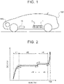
- FIG. 1 is a schematic configuration diagram of a vehicle 100 equipped with a battery management device 10 of the present disclosure.
- the vehicle 100 shown in FIG. 1 is a battery electric vehicle (BEV) including a battery 1 and a motor generator (three-phase alternating current (AC) electric motor) MG.
- the battery 1 is managed by a battery management device 10, and the motor generator MG is connected to the battery 1 via a system main relay (not shown) and a power control device including an inverter etc. (not shown), and can transfer electric power with the battery 1 to output traction power and regenerative braking force.
- the battery 1 of the vehicle 100 can be charged with power from external charging equipment, not shown.
- the battery 1 is a so-called high voltage battery including, for example, multiple battery cells 2 connected in series.
- the battery cells 2 may be distributed and housed in module cases of a plurality of battery modules, not shown, and the battery modules may be connected, for example, in series.
- the battery cells 2 in each battery module are, for example, lithium iron phosphate cells each including a positive electrode (LiFePO positive electrode) made of lithium iron phosphate having an olivine structure, namely LiFePO 4 , and a negative electrode made of a graphite carbon material etc.
- the positive and negative electrodes of each battery cell 2 are housed inside an enclosure together with a separator and an electrolytic solution that is an organic solvent.
- FIG. 2 is a graph showing the relationship between the state of charge (SOC) and the open circuit voltage (OCV) of the battery cell 2.
- the continuous line represents the relationship between the SOC and the OCV during discharging of the battery cell 2
- the dashed line represents the relationship between the SOC and the OCV during charging of the battery cell 2.
- a change in OCV relative to a change in SOC is very small in a wide SOC range. That is, a change in OCV relative to a change in SOC is approximately zero in a range r2 and a range r4 that is a higher SOC range than the range r2 in FIG. 2 .
- the ranges r2, r4 are collectively referred to as “plateau range (first SOC range)."
- a change in OCV relative to a change in SOC is large (slope is steep) in a range r1 that is a lower SOC range than the range r2, a range r3 that is a higher SOC range than the range r2 and a lower SOC range than the range r4 (between the ranges r2 and r4), and a range r5 that is a higher SOC range than the range r4.
- non-plateau range (second SOC range).
- a change in OCV relative to a change in SOC of the battery cells (2) is smaller in the first SOC range than in the second SOC range.
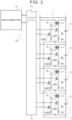
- the battery management device 10 of the vehicle 100 includes: a microcomputer 11 including a central processing unit (CPU), a read-only memory (ROM), and a random access memory (RAM); the same number of (plurality of) cell balancing circuits 15 as the total number of battery cells 2 in the battery 1; and a plurality of management integrated circuits (ICs) 17.
- Each cell balancing circuit 15 includes one flyback transformer Tf, two switching elements SW1, SW2 such as field effect transistors (FETs), and two resistors R1, R2.
- One cell balancing circuit 15 is connected to one battery cell 2.
- a primary coil L1 of each flyback transformer Tf is connected in parallel with a corresponding one of the battery cells 2 via the switching element SW1 and the resistor R1.
- a secondary coil L2 of each flyback transformer Tf is connected in parallel with a plurality of battery cells 2 (in the example of FIG. 3 , four battery cells 2) whose SOCs (voltages) are to be equalized and which forms one group. That is, one end of the secondary coil L2 of each flyback transformer Tf is connected to one ends (e.g., positive electrodes) of the battery cells 2 via a power line. That is, the other end of the secondary coil L2 of each flyback transformer Tf is connected to the other ends (e.g., negative electrodes) of the battery cells 2 via the switching element SW2, the resistor R2, and a power line.
- the switching elements SW1, SW2 of a plurality of cell balancing circuits 15 corresponding to one group can be charged with power discharged from at least one of the battery cells 2 in the group.
- the switching element SW1 of the cell balancing circuit 15 corresponding to the one battery cell 2 is turned on. Thereafter, this switching element SW1 is turned off, and the switching elements SW2 of all the cell balancing circuits 15 in the group are turned on.
- the switching elements SW2 of all the cell balancing circuits 15 in the group are then turned off, and the switching elements SW1 of the cell balancing circuits 15 corresponding to the battery cells 2 other than the one battery cell 2 are turned on.
- the switching elements SW1 of the cell balancing circuits 15 corresponding to the battery cells 2 other than the one battery cell 2 are turned on. Thereafter, these switching elements SW1 are turned off, and the switching elements SW2 of all the cell balancing circuits 15 in the group are turned on. The switching elements SW2 of all the cell balancing circuits 15 in the group are then turned off, and the switching element SW1 of the cell balancing circuit 15 corresponding to the one battery cell 2 is turned on. These processes are then repeatedly performed.
- Each management IC 17 transfers information to and from the microcomputer 11 and controls a corresponding one(s) of the cell balancing circuits 15.
- one management IC 17 is provided for one group of a plurality of (four) battery cells 2 whose SOCs (voltages) are to be equalized.
- Each management IC 17 performs on-off control of the switching elements SW1, SW2 of the corresponding (four) cell balancing circuits 15 according to a command signal from the microcomputer 11.
- Each management IC 17 includes a plurality of (four) voltage sensors (not shown) that detects the voltage of the corresponding (four) battery cells 2.
- Each management IC 17 causes each of the corresponding voltage sensors to detect the voltage of a corresponding one of the battery cells 2 in a predetermined period, and sends the detected value of the voltage sensor to the microcomputer 11.
- Each management IC 17 includes a plurality of (four) current sensors (not shown) that detects a current flowing in the corresponding (four) battery cells 2.
- Each management IC 17 causes each of the corresponding current sensors to detect a current flowing in a corresponding one of the battery cells 2 in a predetermined period, and sends the detected value of the current sensor to the microcomputer 11.
- the microcomputer 11 accumulates the current in each battery cell 2 detected by the corresponding current sensor of the management IC 17 to calculate the SOC of the battery cell 2.
- the microcomputer 11 calculates the OCV of each battery cell 2 based on the detected value of the corresponding voltage sensor of the management IC 17, and derives the SOC of the battery cell 2 corresponding to the calculated OCV from the relationship between the SOC and the OCV in the non-plateau range (see FIG. 2 ).
- the microcomputer 11 uses the SOC of each battery cell 2 derived based on the OCV to correct the SOC of the battery cell 2 calculated based on the current.
- the microcomputer 11 controls the cell balancing circuits 15 in cooperation with the management IC 17 so as to equalize the SOCs (voltages) of the battery cells 2.
- An instrumental panel, not shown, of the vehicle 100 includes an SOC display unit that displays the SOC of the battery 1.
- a display control unit, not shown, of the vehicle 100 displays on the SOC display unit a minimum SOC that is a minimum value of the SOCs of the battery cells 2 calculated by the microcomputer 11 of the battery management device 10.
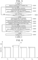
- FIG. 4 is a flowchart showing an example of a routine that is repeatedly executed at predetermined time intervals (very short time intervals) by the microcomputer 11 (CPU) of the battery management device 10 in order to calculate the SOC of each battery cell 2 during system startup of the vehicle 100 with a start switch (ignition (IG) switch), not shown, of the vehicle 100 turned on.
- IG ignition
- the microcomputer 11 acquires the value of a flag F1 (step S100) and determines whether the value of the flag F1 is zero (step S110).
- step S110 determines that the value of the flag F1 is zero (step S110: YES)
- step S120 the microcomputer 11 sets a factor k to be used to calculate the SOC to "1" (step S120).
- step S110: NO the microcomputer 11 sets the factor k to be used to calculate the SOC to a predetermined positive value ⁇ that is smaller than "1" (step S125).
- the value ⁇ is, for example, about 0.95 to 0.99 in consideration of current sensor error (about 1 to 5%).
- the microcomputer 11 sets a variable n (number of the battery cell 2) to "1" (step S140) and calculates the SOC of the nth battery cell 2 (step S150).
- step S150 the microcomputer 11 calculates the current SOC of the nth battery cell 2 by adding the product of the factor k and the current I n of the nth battery cell 2 acquired in step S130 divided by the separately calculated full charge capacity of the nth battery cell 2 to the SOC (previous value) of the nth battery cell 2 calculated during the previous execution of the routine of FIG. 4 .
- the full charge capacity of each battery cell 2 is calculated by correcting, based on temperature frequency information, the value calculated when the SOC of the battery cell 2 is within the non-plateau range.
- the microcomputer 11 increments the variable n (step S160) and determines whether the variable n is larger than the total number N of battery cells 2 (step S170). When the microcomputer 11 determines that the variable n is equal to or less than the total number N of battery cells 2 (step S170: NO), step S150 and the subsequent steps are repeated.
- step S190 NO
- the microcomputer 11 determines that neither of the maximum and minimum SOCs is within the plateau range (step S190: NO)
- the microcomputer 11 resets a counter C (step S195) and ends the routine of FIG. 4 .
- the microcomputer 11 derives the SOC of each battery cell 2 based on the OCV corresponding to the voltage of the battery cell 2, and corrects the SOC of the battery cell 2 calculated based on the current I n by using the SOC obtained based on the derived OCV.
- the microcomputer 11 increments the counter C (step S200) and determines whether the counter C is equal to or larger than a first threshold Cref1 (step S210).
- the first threshold Cref1 used in step S210 is determined so that the product of the first threshold Cref1 and the execution period of the routine of FIG. 4 is, for example, one week (168 hours). That is, the counter C indicates the time during which the SOC of each battery cell 2 stays in the plateau range (range r2 or r4).
- the microcomputer 11 determines that the counter C is less than the first threshold Cref1 (step S210: NO)
- the microcomputer 11 ends the routine of FIG. 4 .
- the microcomputer 11 sets the factor k to the value ⁇ smaller than "1" in step S125 during execution of the routine of FIG. 4 , so that in step S150, the SOC of each battery cell 2 is estimated to be lower than when the SOC is calculated in step S140.
- step S220 NO
- the microcomputer 11 sets the flag F1 to zero and sets the flag F2 to "1" (step S235).
- the microcomputer 11 then ends the routine of FIG. 4 .
- the counter C is equal to or larger than the second threshold Cref2, it means that the SOC of each battery cell 2 has stayed in the plateau range (range r2 or r4) for one month or more.
- the switching elements SW1, SW2 of the cell balancing circuits 15 are controlled so that the battery cells 2 1 , 2 3 , and 2 4 other than the battery cell 2 2 that is a forced SOC change cell 2x are charged with power discharged from the battery cell 2 2 .
- the microcomputer 11 determines whether the SOC of the forced SOC change cell 2x calculated in step S380 is approximately equal to the SOC of the forced SOC change cell 2x before the forced change calculated in step S150 of FIG. 4 immediately before executing the routine of FIG. 5 (step S390). When the microcomputer 11 determines that the SOC of the forced SOC change cell 2x calculated in step S380 is not approximately equal to the SOC before the forced change (step S390: NO), the microcomputer 11 repeats steps S370 to S390.
- the battery cells 2 of the battery 1 are lithium iron phosphate cells.
- the present disclosure is not limited to this. That is, the battery cells 2 of the battery 1 that is managed by the battery management device 10 may be battery cells other than the lithium iron phosphate cells as long as a change in OCV relative to a change in SOC is small in the plateau range and large in the non-plateau range.
- the microcomputer 11 that is an SOC calculation unit calculates the SOC of each battery block B by accumulating a current in the battery block B detected by the current sensor, not shown, of the management IC 17.
- the microcomputer 11 that is a cell balancing unit controls the switching elements SW1, SW2 of the corresponding cell balancing circuits 15 so that the SOC of a forced SOC change battery block (target battery block) that is one of the battery blocks B falls within the non-plateau range.
Landscapes
- Engineering & Computer Science (AREA)
- Power Engineering (AREA)
- Life Sciences & Earth Sciences (AREA)
- Sustainable Development (AREA)
- Sustainable Energy (AREA)
- Transportation (AREA)
- Mechanical Engineering (AREA)
- Secondary Cells (AREA)
- Charge And Discharge Circuits For Batteries Or The Like (AREA)
- Tests Of Electric Status Of Batteries (AREA)
- Electric Propulsion And Braking For Vehicles (AREA)
Applications Claiming Priority (1)
| Application Number | Priority Date | Filing Date | Title |
|---|---|---|---|
| JP2021130377A JP2023024201A (ja) | 2021-08-06 | 2021-08-06 | バッテリ管理装置および方法 |
Publications (1)
| Publication Number | Publication Date |
|---|---|
| EP4129750A1 true EP4129750A1 (de) | 2023-02-08 |
Family
ID=82701788
Family Applications (1)
| Application Number | Title | Priority Date | Filing Date |
|---|---|---|---|
| EP22186455.6A Pending EP4129750A1 (de) | 2021-08-06 | 2022-07-22 | Batteriemanagementvorrichtung und -verfahren |
Country Status (4)
| Country | Link |
|---|---|
| US (1) | US20230039175A1 (de) |
| EP (1) | EP4129750A1 (de) |
| JP (1) | JP2023024201A (de) |
| CN (1) | CN115706442A (de) |
Citations (3)
| Publication number | Priority date | Publication date | Assignee | Title |
|---|---|---|---|---|
| JP2010283922A (ja) | 2009-06-02 | 2010-12-16 | Toyota Motor Corp | 車両の制御装置 |
| US20120274283A1 (en) * | 2011-04-28 | 2012-11-01 | Van Lammeren Johannes | Battery cell-balancing method and apparatus |
| CN112599932A (zh) * | 2021-01-08 | 2021-04-02 | 蔚来汽车科技(安徽)有限公司 | 电池包、方法和车辆 |
-
2021
- 2021-08-06 JP JP2021130377A patent/JP2023024201A/ja active Pending
-
2022
- 2022-07-18 US US17/866,879 patent/US20230039175A1/en active Pending
- 2022-07-22 EP EP22186455.6A patent/EP4129750A1/de active Pending
- 2022-08-02 CN CN202210923872.XA patent/CN115706442A/zh active Pending
Patent Citations (5)
| Publication number | Priority date | Publication date | Assignee | Title |
|---|---|---|---|---|
| JP2010283922A (ja) | 2009-06-02 | 2010-12-16 | Toyota Motor Corp | 車両の制御装置 |
| US20120065824A1 (en) * | 2009-06-02 | 2012-03-15 | Kenji Takahashi | Control apparatus for vehicle |
| US20120274283A1 (en) * | 2011-04-28 | 2012-11-01 | Van Lammeren Johannes | Battery cell-balancing method and apparatus |
| CN112599932A (zh) * | 2021-01-08 | 2021-04-02 | 蔚来汽车科技(安徽)有限公司 | 电池包、方法和车辆 |
| US20220223901A1 (en) * | 2021-01-08 | 2022-07-14 | Nio Technology (Anhui) Co., Ltd | Battery pack, method and vehicle |
Also Published As
| Publication number | Publication date |
|---|---|
| CN115706442A (zh) | 2023-02-17 |
| JP2023024201A (ja) | 2023-02-16 |
| US20230039175A1 (en) | 2023-02-09 |
Similar Documents
| Publication | Publication Date | Title |
|---|---|---|
| JP6939057B2 (ja) | 車載の電池システムおよび電池の経年劣化推定方法 | |
| JP6822300B2 (ja) | 充電率推定方法および車載の電池システム | |
| US8493031B2 (en) | Equalization device, battery system and electric vehicle including the same, equalization processing program, and equalization processing method | |
| KR101589155B1 (ko) | 전기 저장 시스템 | |
| CN107817450B (zh) | 蓄电元件包及管理装置、soc推测方法、介质、面板系统 | |
| CN108292854B (zh) | 电池控制装置 | |
| JP5862836B2 (ja) | 電池システム | |
| EP2328256A2 (de) | Ausgleichsvorrichtung, Ausgleichsverarbeitungsprogramm, Batteriesystem, Elektrofahrzeug und Ausgleichsverarbeitungsverfahren | |
| EP2847026B1 (de) | Elektrisches speichersystem und entzerrungsverfahren dafür | |
| EP2178187A1 (de) | Stromquellensystem, fahrzeug damit und steuerverfahren für das stromquellensystem | |
| JP2003303627A (ja) | 状態検知装置及びこれを用いた各種装置 | |
| JP5397013B2 (ja) | 組電池の制御装置 | |
| US20170163069A1 (en) | Battery Controlling Device | |
| JP2017184534A (ja) | 蓄電素子管理装置、蓄電装置、及び蓄電システム | |
| US20120276440A1 (en) | Battery pack | |
| JP2019187027A (ja) | 蓄電装置 | |
| JP7140082B2 (ja) | センサ異常判定装置 | |
| CN104835988A (zh) | 电池系统和电池系统荷电状态soc的修正方法 | |
| EP4129750A1 (de) | Batteriemanagementvorrichtung und -verfahren | |
| CN113016099B (zh) | 电池控制装置 | |
| CN112829635A (zh) | 电动车辆电池中的析锂检测和缓解 | |
| Zahedi et al. | Globally Optimal Energy Management in a Battery-Ultracapacitor Electric Vehicle | |
| WO2022138745A1 (ja) | 電池制御装置及び電池システム | |
| US20240022099A1 (en) | Storage battery control device, power storage system, and storage battery control method | |
| US20230324467A1 (en) | Control device for secondary battery and method for estimating full charge capacity of secondary battery |
Legal Events
| Date | Code | Title | Description |
|---|---|---|---|
| PUAI | Public reference made under article 153(3) epc to a published international application that has entered the european phase |
Free format text: ORIGINAL CODE: 0009012 |
|
| STAA | Information on the status of an ep patent application or granted ep patent |
Free format text: STATUS: REQUEST FOR EXAMINATION WAS MADE |
|
| 17P | Request for examination filed |
Effective date: 20220722 |
|
| AK | Designated contracting states |
Kind code of ref document: A1 Designated state(s): AL AT BE BG CH CY CZ DE DK EE ES FI FR GB GR HR HU IE IS IT LI LT LU LV MC MK MT NL NO PL PT RO RS SE SI SK SM TR |