EP4129728A1 - Shutter device - Google Patents
Shutter device Download PDFInfo
- Publication number
- EP4129728A1 EP4129728A1 EP21779727.3A EP21779727A EP4129728A1 EP 4129728 A1 EP4129728 A1 EP 4129728A1 EP 21779727 A EP21779727 A EP 21779727A EP 4129728 A1 EP4129728 A1 EP 4129728A1
- Authority
- EP
- European Patent Office
- Prior art keywords
- flap
- link mechanism
- actuator
- connecting rod
- stopper
- Prior art date
- Legal status (The legal status is an assumption and is not a legal conclusion. Google has not performed a legal analysis and makes no representation as to the accuracy of the status listed.)
- Pending
Links
- 230000007246 mechanism Effects 0.000 claims abstract description 60
- 230000008878 coupling Effects 0.000 claims abstract description 24
- 238000010168 coupling process Methods 0.000 claims abstract description 24
- 238000005859 coupling reaction Methods 0.000 claims abstract description 24
- 230000005856 abnormality Effects 0.000 abstract description 8
- 230000002159 abnormal effect Effects 0.000 description 12
- 238000001514 detection method Methods 0.000 description 9
- 238000010586 diagram Methods 0.000 description 5
- 230000009467 reduction Effects 0.000 description 3
- 238000000034 method Methods 0.000 description 2
- 238000002485 combustion reaction Methods 0.000 description 1
- 230000000694 effects Effects 0.000 description 1
- 238000005057 refrigeration Methods 0.000 description 1
- 230000007704 transition Effects 0.000 description 1
Images


Classifications
-
- B—PERFORMING OPERATIONS; TRANSPORTING
- B60—VEHICLES IN GENERAL
- B60K—ARRANGEMENT OR MOUNTING OF PROPULSION UNITS OR OF TRANSMISSIONS IN VEHICLES; ARRANGEMENT OR MOUNTING OF PLURAL DIVERSE PRIME-MOVERS IN VEHICLES; AUXILIARY DRIVES FOR VEHICLES; INSTRUMENTATION OR DASHBOARDS FOR VEHICLES; ARRANGEMENTS IN CONNECTION WITH COOLING, AIR INTAKE, GAS EXHAUST OR FUEL SUPPLY OF PROPULSION UNITS IN VEHICLES
- B60K11/00—Arrangement in connection with cooling of propulsion units
- B60K11/08—Air inlets for cooling; Shutters or blinds therefor
- B60K11/085—Air inlets for cooling; Shutters or blinds therefor with adjustable shutters or blinds
-
- B—PERFORMING OPERATIONS; TRANSPORTING
- B60—VEHICLES IN GENERAL
- B60Y—INDEXING SCHEME RELATING TO ASPECTS CROSS-CUTTING VEHICLE TECHNOLOGY
- B60Y2306/00—Other features of vehicle sub-units
- B60Y2306/13—Failsafe arrangements
-
- B—PERFORMING OPERATIONS; TRANSPORTING
- B60—VEHICLES IN GENERAL
- B60Y—INDEXING SCHEME RELATING TO ASPECTS CROSS-CUTTING VEHICLE TECHNOLOGY
- B60Y2306/00—Other features of vehicle sub-units
- B60Y2306/15—Failure diagnostics
-
- B—PERFORMING OPERATIONS; TRANSPORTING
- B60—VEHICLES IN GENERAL
- B60Y—INDEXING SCHEME RELATING TO ASPECTS CROSS-CUTTING VEHICLE TECHNOLOGY
- B60Y2400/00—Special features of vehicle units
- B60Y2400/40—Actuators for moving a controlled member
- B60Y2400/41—Mechanical transmissions for actuators
- B60Y2400/411—Bowden cables or linkages
- B60Y2400/4115—Lost motion linkages
-
- F—MECHANICAL ENGINEERING; LIGHTING; HEATING; WEAPONS; BLASTING
- F16—ENGINEERING ELEMENTS AND UNITS; GENERAL MEASURES FOR PRODUCING AND MAINTAINING EFFECTIVE FUNCTIONING OF MACHINES OR INSTALLATIONS; THERMAL INSULATION IN GENERAL
- F16H—GEARING
- F16H21/00—Gearings comprising primarily only links or levers, with or without slides
- F16H21/10—Gearings comprising primarily only links or levers, with or without slides all movement being in, or parallel to, a single plane
- F16H21/16—Gearings comprising primarily only links or levers, with or without slides all movement being in, or parallel to, a single plane for interconverting rotary motion and reciprocating motion
- F16H21/18—Crank gearings; Eccentric gearings
- F16H21/22—Crank gearings; Eccentric gearings with one connecting-rod and one guided slide to each crank or eccentric
-
- Y—GENERAL TAGGING OF NEW TECHNOLOGICAL DEVELOPMENTS; GENERAL TAGGING OF CROSS-SECTIONAL TECHNOLOGIES SPANNING OVER SEVERAL SECTIONS OF THE IPC; TECHNICAL SUBJECTS COVERED BY FORMER USPC CROSS-REFERENCE ART COLLECTIONS [XRACs] AND DIGESTS
- Y02—TECHNOLOGIES OR APPLICATIONS FOR MITIGATION OR ADAPTATION AGAINST CLIMATE CHANGE
- Y02T—CLIMATE CHANGE MITIGATION TECHNOLOGIES RELATED TO TRANSPORTATION
- Y02T10/00—Road transport of goods or passengers
- Y02T10/80—Technologies aiming to reduce greenhouse gasses emissions common to all road transportation technologies
- Y02T10/88—Optimized components or subsystems, e.g. lighting, actively controlled glasses
Definitions
- the present invention relates to a shutter device that is disposed in a front portion of a front room of a vehicle and that is for adjusting an amount of outside air introduced into the front room.
- An automatic vehicle has, on a front side thereof, a room called an engine room, a motor room, or the like (hereinafter, referred to as a "front room" for convenience of description in the present description) separated from a vehicle compartment for an occupant to ride in.
- the front room stores a prime mover such as an internal combustion engine or an electric motor, a battery, a refrigeration cycle of an air conditioner, and the like.
- the front room has a front surface provided with a front grille having an opening for introducing the outside air into the front room.
- Patent Literature 1 describes such a shutter device.
- the shutter device includes a plurality of closing elements (also referred to as flaps, fins, or the like) arranged in an up and down direction.
- Each of these closing elements is rotatably supported by a frame, and is pivotally attached to a common arm. By driving the arm by an actuator, the closing elements rotate in conjunction with each other and the front grille is opened and closed.
- a shutter device of this form when coupling between any one of the closing elements and the arm is released, the one closing element cannot move. If the released closing element does not interfere with movement of the other closing elements, it is difficult to recognize that the one closing element is released. In this case, a situation that an amount of air passing through the front grille is different from an intended amount may continue for a long period of time.
- Patent Literature 1 JP-A-2016-147552
- An object of the invention is to provide a vehicle shutter device having a function capable of, when an abnormality occurs in a link mechanism that transmits power from an actuator to flaps, easily detecting the occurrence of the abnormality.
- An embodiment of the present invention provides a vehicle shutter device including: a support frame; a first flap attached to the support frame so as to be rotatable about a first rotation axis; a second flap attached to the support frame so as to be rotatable about a second rotation axis parallel to the first rotation axis; one actuator configured to generate a driving force for rotating the first flap and the second flap; and a link mechanism configured to transmit the driving force generated by the actuator to the first flap and the second flap, the link mechanism including a connecting rod that couples the first flap and the second flap to each other such that the first flap and the second flap rotate in synchronization with each other, a first pivotally attaching portion of the connecting rod being pivotally attached to the first flap, a second pivotally attaching portion being pivotally attached to the second flap, in which the shutter device further includes a stopper configured to, when the link mechanism is in a normal state, prohibit each of the first flap and the second flap from being displaced beyond normal opening and closing ranges between fully open positions and fully closed positions, and
- the actuator when the coupling between the flap and the link mechanism is released, the actuator is allowed to rotate beyond the normal rotation range. Therefore, the abnormality in the link mechanism can be detected based on a detection result of a rotation position detector of the actuator.
- FIG. 1 is a schematic perspective view of a right half of a vehicle shutter device as viewed from an inside of a front room (for a definition of the "front room", refer to the section of Background Art at the beginning of the present description).
- a rear side (upper left) in FIG. 1 is an outside of the vehicle (a space outside the front room), and a front side (lower right) in FIG. 1 is an inside of the front room.
- the vehicle shutter device includes: a support frame 2; a first flap 10 attached to the support frame 2 so as to be rotatable about a first rotation axis; a second flap 20 attached to the support frame 2 so as to be rotatable about a second rotation axis parallel to the first rotation axis; and an actuator 50 that generates a driving force for rotating the first flap 10 and the second flap 20.
- the first rotation axis and the second rotation axis extend horizontally in a vehicle width direction (left and right direction) of the vehicle.
- the first flap 10 includes a first closing plate 10A that opens and closes a front grille, and a first disk 10B that is provided on a side surface of the first closing plate and that extends in a radial direction of the first rotation axis.
- the second flap 20 includes a plate-shaped second closing plate 20Athat opens and closes the front grille, and a second disk 20B that is provided on a side surface of the second closing plate 20A and that extends in a radial direction of the second rotation axis.
- first flap 10 and the second flap 20 are provided with shafts 12 and 22 at both longitudinal ends (only one end side is shown in FIG. 2 ) thereof, respectively.
- These shafts 12 and 22 are rotatably supported by bearings (not shown) provided on the support frame 2.
- the first rotation axis and the second rotation axis pass through centers of the shafts 12 and 22, respectively.
- the actuator 50 includes at least an electric rotary motor.
- the actuator 50 may further include a speed reduction mechanism (for example, a speed reduction gear mechanism).
- the actuator 50 includes an output shaft (rotary shaft) 52 that is, for example, a rotary shaft of the electric rotary motor or an output shaft of the speed reduction mechanism attached to the rotary shaft of the electric rotary motor so as to transmit power.
- the shutter device includes a link mechanism 30 that transmits the driving force generated by the actuator 50 to the first flap 10 and the second flap 20.
- the link mechanism 30 includes a connecting rod 31 and a pivoting arm 40.
- the connecting rod 31 couples the first flap 10 and the second flap 20 to each other such that the first flap 10 and the second flap 20 rotate in synchronization with each other (preferably in the same phase as each other).
- the connecting rod 31 includes a first pivotally attaching portion 32 pivotally attached to the first disk 10B of the first flap 10, and a second pivotally attaching portion 34 pivotally attached to the second disk 20B of the second flap 20.
- the first disk 10B is provided with a cylindrical pin 14.
- a hole (also referred to as a "hole 32") is formed in a part of the connecting rod 31 where the first pivotally attaching portion 32 is provided.
- the pin 14 is rotatably inserted into the hole 32.
- the second disk 20B is provided with a cylindrical pin 24.
- a hole also referred to as a "hole 34" is formed in a part of the connecting rod 31 where the second pivotally attaching portion 34 is provided.
- the pin 24 is rotatably inserted into the hole 34.
- the pins 14 and 24 are attached to the corresponding holes 32 and 34 by an attachment method that prevents the pins 14 and 24 from being easily decoupled.
- the connecting rod 31 may be provided with pins, and the first flap 10 and the second
- the pins 14 and 24 may have a large diameter head portion slightly smaller than a diameter of the holes 32 and 34 of the connecting rod 31 and may be each provided with a large-diameter head, and the large-diameter heads may be forcibly passed through the holes 32 and 34 respectively, or (ii) the pins 14 and 24 may be each formed with a female screw, and after the pins 14 and 24 are passed through the holes 32 and 34 respectively, a male screw having a diameter larger than the diameter of the holes 32 and 34 may be screwed into the female screw.
- the connecting rod 31 is provided with an elongated hole 36 in the vicinity of the second pivotally attaching portion 34.
- the elongated hole 36 is slidably engaged with a slider 42.
- the pivoting arm 40 has one end fixed to the output shaft 52 of the actuator 50.
- the pivoting arm 40 has the other end fixed with the slider 42.
- a rotation axis of the pivoting arm 40 that is, a center of the output shaft 52, does not coincide with the rotation axis of the second flap 20, that is, the center of the shaft 22, when the link mechanism 30 transitions from a state in (A) of FIG. 2 to a state in (B) of FIG. 2 (or vice versa), the slider 42 moves in the elongated hole 36 in a longitudinal direction (relatively to the elongated hole 36) as the pivoting arm 40 is pivoted (which is, however, slightly difficult to understand from (A) and (B) of FIG. 2 ).
- the slider 42 when the second flap 20 is located at the fully closed position, the slider 42 is located at a position (first position) in the elongated hole 36, and when the second flap 20 is located at the fully open position, the slider 42 is located at a second position in the elongated hole 36.
- the slider 42 is disposed in the elongated hole 36 with a slight clearance. That is, the slider 42 has a diameter slightly smaller than a short diameter of the elongated hole 36.
- the support frame 2 is provided with frame stoppers 4 and 6.
- the first flap 10 is provided with a flap stopper 16 that abuts against the frame stopper 4 to restrict a rotational movement of the first flap 10. More specifically, as shown in FIG. 1 , the flap stopper 16 is provided on the first closing plate 10A.
- the second flap 20 is provided with flap stoppers 28 and 29 that abut against the frame stopper 6 to restrict a rotational movement of the second flap 20. More specifically, the flap stoppers 28 and 29 are provided on the second disk 20B.
- frame stopper means a stopper provided on the support frame 2
- the term “flap stopper” means a stopper provided on the flap (10 or 20).
- the frame stoppers 4 and 6 and the flap stoppers 28 and 29 prevent the first flap 10 and the second flap 20 from rotating beyond the fully closed positions when the first flap 10 and the second flap 20 rotate toward the fully closed positions, and prevent the first flap 10 and the second flap 20 from rotating beyond the fully open positions when the first flap 10 and the second flap 20 rotate toward the fully open positions.
- the second flap 20 is provided with the flap stopper 28.
- the flap stopper 28 is located at a position that coincides with the elongated hole 36 of the connecting rod 31, and thus is difficult to see.
- the flap stopper 28 collides with the frame stopper 6 to prevent the second flap 20 from rotating beyond the fully open position.
- the flap stopper 28 and the frame stopper 6 also prevent the first flap 10, which is coupled to the second flap 20 via the connecting rod 31, from rotating beyond the fully open position.
- Coupling portions between the elements of the link mechanism 30 are configured so as not to be easily decoupled, but in an unlikely event that a coupling portion is decoupled, such decoupling can be easily detected.
- States in which the coupling portion is released are classified into three cases and will be described below.
- FIG. 3 shows a first abnormal state of the link mechanism 30.
- the first abnormal state means a state where coupling between the connecting rod 31 and the first flap 10 is released (the pin 14 and the hole 32 are separated), and coupling and engagement of the other portions of the link mechanism 30 are maintained.
- the coupling between the first pivotally attaching portion 32 of the connecting rod 31 and the pin 14 of the first flap 10 is released, so that the connecting rod 31 can freely rotate about the pin 24 of the second flap 20. Therefore, the output shaft 52 of the actuator 50 can be rotated until the slider 42 attached to the pivoting arm 40 reaches an end of the elongated hole 36 (that is, a third position farther from the first position than the second position).
- the pivot angle range of the pivoting arm 40 (that is, the rotation angle range of the output shaft 52) is indicated by " ⁇ A" in (B) of FIG. 3 .
- Rotation of the output shaft 52 of the actuator 50 beyond the rotation angle range ⁇ N is detected by a rotation angle detection unit 54 (schematically shown only in FIG. 1 ) provided in the actuator 50.
- the rotation angle detection unit may be, for example, a rotary encoder attached to the electric rotary motor of the actuator 50.
- the output shaft 52 of the actuator 50 rotating beyond the rotation angle range ⁇ N means that an abnormality has occurred in the link mechanism 30.
- Such abnormality can be notified to an occupant by, for example, a notification unit.
- a notification unit for example, a warning lamp provided in a meter unit of an instrument panel and/or a chime or a buzzer may be used.
- the actuator 50 When the rotation angle detection unit detects that the output shaft 52 of the actuator 50 rotates beyond the rotation angle range ⁇ N, the actuator 50 may be stopped (the actuator 50 may come to an emergency stop) in order to prevent the link mechanism 30 and the actuator 50 from being damaged.
- the notification and/or the stop of the actuator 50 based on the detection described above can be performed via a control unit (not shown).
- FIG. 4 shows a second abnormal state of the link mechanism 30.
- the second abnormal state means a state where coupling between the connecting rod 31 and the second flap 20 is released (the pin 24 and the hole 34 are separated), and coupling and engagement of the other portions of the link mechanism 30 are maintained.
- FIG. 5 shows a third abnormal state of the link mechanism 30.
- the third abnormal state means a state where coupling between the connecting rod 31 and the pivoting arm 40 is released (the elongated hole 36 and the slider 42 are separated), and coupling and engagement of other the portions of the link mechanism 30 are maintained.
- the output shaft 52 can freely rotate beyond the rotation angle range ⁇ C until the output shaft 52 collides with, for example, the connecting rod 31, but in actual operation, an operation of the actuator 50 is stopped when the output shaft 52 is about to exceed the rotation angle range ⁇ C. Also, in this case, the rotation angle detection unit detects that the output shaft 52 of the actuator 50 rotates beyond the rotation angle range ⁇ N, and the notification unit notifies the occupant that an abnormality has occurred in the link mechanism 30.
- the embodiment it is possible to easily determine that coupling or engagement between elements provided in the link mechanism 30 is released.
- the rotation angle detection unit (54) for detecting a rotation angle of the output shaft 52 of the actuator 50 is provided, so that it is not necessary to provide another rotation angle detection unit. Therefore, it is possible to prevent or limit an increase in cost of the shutter device for realizing the above functions.
- the actuator 50 and the link mechanism 30 may be arranged as shown in FIG. 6 in a manner turned upside down with respect to the embodiment shown in FIGS. 1 to 5 .
- a shutter device shown in FIG. 6 operates in the same manner as the shutter device shown in FIGS. 1 to 5 .
Abstract
Description
- The present invention relates to a shutter device that is disposed in a front portion of a front room of a vehicle and that is for adjusting an amount of outside air introduced into the front room.
- An automatic vehicle has, on a front side thereof, a room called an engine room, a motor room, or the like (hereinafter, referred to as a "front room" for convenience of description in the present description) separated from a vehicle compartment for an occupant to ride in. The front room stores a prime mover such as an internal combustion engine or an electric motor, a battery, a refrigeration cycle of an air conditioner, and the like. The front room has a front surface provided with a front grille having an opening for introducing the outside air into the front room.
- In recent years, in order to improve aerodynamic characteristics of the vehicle, to achieve efficient warming-up, and the like, the front grille is provided with a shutter device that can be opened and closed, and the front grille is closed depending on a situation. Patent Literature 1 describes such a shutter device. The shutter device includes a plurality of closing elements (also referred to as flaps, fins, or the like) arranged in an up and down direction. Each of these closing elements is rotatably supported by a frame, and is pivotally attached to a common arm. By driving the arm by an actuator, the closing elements rotate in conjunction with each other and the front grille is opened and closed.
- In a shutter device of this form, when coupling between any one of the closing elements and the arm is released, the one closing element cannot move. If the released closing element does not interfere with movement of the other closing elements, it is difficult to recognize that the one closing element is released. In this case, a situation that an amount of air passing through the front grille is different from an intended amount may continue for a long period of time.
- Patent Literature 1:
JP-A-2016-147552 - An object of the invention is to provide a vehicle shutter device having a function capable of, when an abnormality occurs in a link mechanism that transmits power from an actuator to flaps, easily detecting the occurrence of the abnormality.
- An embodiment of the present invention provides a vehicle shutter device including: a support frame; a first flap attached to the support frame so as to be rotatable about a first rotation axis; a second flap attached to the support frame so as to be rotatable about a second rotation axis parallel to the first rotation axis; one actuator configured to generate a driving force for rotating the first flap and the second flap; and a link mechanism configured to transmit the driving force generated by the actuator to the first flap and the second flap, the link mechanism including a connecting rod that couples the first flap and the second flap to each other such that the first flap and the second flap rotate in synchronization with each other, a first pivotally attaching portion of the connecting rod being pivotally attached to the first flap, a second pivotally attaching portion being pivotally attached to the second flap, in which the shutter device further includes a stopper configured to, when the link mechanism is in a normal state, prohibit each of the first flap and the second flap from being displaced beyond normal opening and closing ranges between fully open positions and fully closed positions, and the link mechanism is configured such that when coupling between the connecting rod and the first flap is released in the first pivotally attaching portion in a state where coupling between the connecting rod and the second flap is maintained in the second pivotally attaching portion, the actuator is allowed to rotate beyond a normal rotation range corresponding to the normal opening and closing ranges of the first flap and the second flap.
- According to the embodiment, when the coupling between the flap and the link mechanism is released, the actuator is allowed to rotate beyond the normal rotation range. Therefore, the abnormality in the link mechanism can be detected based on a detection result of a rotation position detector of the actuator.
-
-
FIG. 1 is a schematic perspective view of a right half of a vehicle shutter device as viewed from an inside of a front room. -
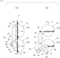
FIG. 2 is a diagram showing a configuration of a link mechanism according to an embodiment and an operation of the link mechanism in a normal state, in which (A) shows a state of the link mechanism when flaps are in a fully closed state, and (B) shows a state of the link mechanism when the flaps are in a fully open state. -
FIG. 3 is a diagram showing an operation of the link mechanism when coupling between a connecting rod and a first flap is released (first abnormal state), in which (A) shows a state of the link mechanism when an actuator is at the same rotation angle position as in (B) ofFIG. 2 , and (B) shows a state of the link mechanism when the actuator is displaced beyond the rotation angle position in (A). -
FIG. 4 is a diagram showing an operation of the link mechanism when coupling between the connecting rod and a second flap is released (second abnormal state), in which (A) shows a state of the link mechanism when the actuator is at the same rotation angle position as in (B) ofFIG. 2 , and (B) shows a state of the link mechanism when the actuator is displaced beyond the rotation angle position in (A). -
FIG. 5 is a diagram showing an operation of the link mechanism when coupling between the connecting rod and a pivoting arm is released (third abnormal state), in which (A) shows a state of the link mechanism when the actuator is at the same rotation angle position as in (B) ofFIG. 2 , and (B) shows a state of the link mechanism when the actuator is displaced beyond the rotation angle position in (A). -
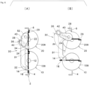
FIG. 6 is a diagram showing a configuration of a link mechanism according to another embodiment and an operation of the link mechanism in a normal state, in which (A) shows a state of the link mechanism when flaps are in a fully closed state, and (B) shows a state of the link mechanism when the flaps are in a fully open state. - Hereinafter, an embodiment of the invention will be described with reference to drawings.
-
FIG. 1 is a schematic perspective view of a right half of a vehicle shutter device as viewed from an inside of a front room (for a definition of the "front room", refer to the section of Background Art at the beginning of the present description). A rear side (upper left) inFIG. 1 is an outside of the vehicle (a space outside the front room), and a front side (lower right) inFIG. 1 is an inside of the front room. - As shown in
FIGS. 1 and2 , the vehicle shutter device includes: asupport frame 2; afirst flap 10 attached to thesupport frame 2 so as to be rotatable about a first rotation axis; asecond flap 20 attached to thesupport frame 2 so as to be rotatable about a second rotation axis parallel to the first rotation axis; and anactuator 50 that generates a driving force for rotating thefirst flap 10 and thesecond flap 20. Normally, the first rotation axis and the second rotation axis extend horizontally in a vehicle width direction (left and right direction) of the vehicle. - The
first flap 10 includes afirst closing plate 10A that opens and closes a front grille, and afirst disk 10B that is provided on a side surface of the first closing plate and that extends in a radial direction of the first rotation axis. Thesecond flap 20 includes a plate-shaped second closing plate 20Athat opens and closes the front grille, and asecond disk 20B that is provided on a side surface of thesecond closing plate 20A and that extends in a radial direction of the second rotation axis. - As shown in
FIG. 2 , thefirst flap 10 and thesecond flap 20 are provided withshafts FIG. 2 ) thereof, respectively. Theseshafts support frame 2. The first rotation axis and the second rotation axis pass through centers of theshafts - The
actuator 50 includes at least an electric rotary motor. Theactuator 50 may further include a speed reduction mechanism (for example, a speed reduction gear mechanism). Theactuator 50 includes an output shaft (rotary shaft) 52 that is, for example, a rotary shaft of the electric rotary motor or an output shaft of the speed reduction mechanism attached to the rotary shaft of the electric rotary motor so as to transmit power. - The shutter device includes a
link mechanism 30 that transmits the driving force generated by theactuator 50 to thefirst flap 10 and thesecond flap 20. Thelink mechanism 30 includes a connectingrod 31 and apivoting arm 40. - The connecting
rod 31 couples thefirst flap 10 and thesecond flap 20 to each other such that thefirst flap 10 and thesecond flap 20 rotate in synchronization with each other (preferably in the same phase as each other). - The connecting
rod 31 includes a first pivotally attachingportion 32 pivotally attached to thefirst disk 10B of thefirst flap 10, and a second pivotally attachingportion 34 pivotally attached to thesecond disk 20B of thesecond flap 20. Specifically, thefirst disk 10B is provided with acylindrical pin 14. A hole (also referred to as a "hole 32") is formed in a part of the connectingrod 31 where the first pivotally attachingportion 32 is provided. Thepin 14 is rotatably inserted into thehole 32. Similarly, thesecond disk 20B is provided with acylindrical pin 24. A hole (also referred to as a "hole 34") is formed in a part of the connectingrod 31 where the second pivotally attachingportion 34 is provided. Thepin 24 is rotatably inserted into thehole 34. Thepins corresponding holes pins rod 31 may be provided with pins, and thefirst flap 10 and thesecond flap 20 may be provided with holes. - As the attachment method that prevents the
pins pins holes rod 31 and may be each provided with a large-diameter head, and the large-diameter heads may be forcibly passed through theholes pins pins holes holes - The connecting
rod 31 is provided with anelongated hole 36 in the vicinity of the second pivotally attachingportion 34. Theelongated hole 36 is slidably engaged with aslider 42. Thepivoting arm 40 has one end fixed to theoutput shaft 52 of theactuator 50. Thepivoting arm 40 has the other end fixed with theslider 42. - As shown in
FIG. 2 , when thelink mechanism 30 is in a normal state, as theactuator 50 pivots thepivoting arm 40, thefirst flap 10 and thesecond flap 20 rotate in conjunction with each other about 90 degrees in rotation angle ranges (hereinafter also referred to as "normal opening and closing ranges") between fully closed positions shown in (A) ofFIG. 2 and fully open positions shown in (B) ofFIG. 2 . That is, at this time, rotation angle positions of thefirst flap 10 and thesecond flap 20 are determined according to a rotation angle position of thepivoting arm 40. A pivot angle range of the pivoting arm 40 (that is, a rotation angle range of the output shaft 52) at this time is indicated by "θN" in (B) ofFIG. 2 . - Since a rotation axis of the
pivoting arm 40, that is, a center of theoutput shaft 52, does not coincide with the rotation axis of thesecond flap 20, that is, the center of theshaft 22, when thelink mechanism 30 transitions from a state in (A) ofFIG. 2 to a state in (B) ofFIG. 2 (or vice versa), theslider 42 moves in theelongated hole 36 in a longitudinal direction (relatively to the elongated hole 36) as thepivoting arm 40 is pivoted (which is, however, slightly difficult to understand from (A) and (B) ofFIG. 2 ). That is, when thesecond flap 20 is located at the fully closed position, theslider 42 is located at a position (first position) in theelongated hole 36, and when thesecond flap 20 is located at the fully open position, theslider 42 is located at a second position in theelongated hole 36. - In order to prevent the
slider 42 from being locked in theelongated hole 36, theslider 42 is disposed in theelongated hole 36 with a slight clearance. That is, theslider 42 has a diameter slightly smaller than a short diameter of theelongated hole 36. - The
support frame 2 is provided withframe stoppers first flap 10 is provided with aflap stopper 16 that abuts against theframe stopper 4 to restrict a rotational movement of thefirst flap 10. More specifically, as shown inFIG. 1 , theflap stopper 16 is provided on thefirst closing plate 10A. Thesecond flap 20 is provided withflap stoppers frame stopper 6 to restrict a rotational movement of thesecond flap 20. More specifically, theflap stoppers second disk 20B. Here, the term "frame stopper" means a stopper provided on thesupport frame 2, and the term "flap stopper" means a stopper provided on the flap (10 or 20). Theframe stoppers flap stoppers first flap 10 and thesecond flap 20 from rotating beyond the fully closed positions when thefirst flap 10 and thesecond flap 20 rotate toward the fully closed positions, and prevent thefirst flap 10 and thesecond flap 20 from rotating beyond the fully open positions when thefirst flap 10 and thesecond flap 20 rotate toward the fully open positions. - As shown in (B) of
FIG. 2 , thesecond flap 20 is provided with theflap stopper 28. In (A) ofFIG. 2 , theflap stopper 28 is located at a position that coincides with theelongated hole 36 of the connectingrod 31, and thus is difficult to see. When thesecond flap 20 rotates toward the fully open position, theflap stopper 28 collides with theframe stopper 6 to prevent thesecond flap 20 from rotating beyond the fully open position. As shown inFIG. 2 , as long as thelink mechanism 30 is in the normal state, theflap stopper 28 and theframe stopper 6 also prevent thefirst flap 10, which is coupled to thesecond flap 20 via the connectingrod 31, from rotating beyond the fully open position. - As is clear from the arrangement of the stoppers described above, when the
link mechanism 30 is in the normal state, thefirst flap 10 and thesecond flap 20 cannot rotate beyond the "normal opening and closing ranges" described above, and thus theoutput shaft 52 of theactuator 50 cannot rotate beyond the rotation angle range θN. - Coupling portions between the elements of the
link mechanism 30 are configured so as not to be easily decoupled, but in an unlikely event that a coupling portion is decoupled, such decoupling can be easily detected. States in which the coupling portion is released (abnormal states) are classified into three cases and will be described below. -
FIG. 3 shows a first abnormal state of thelink mechanism 30. The first abnormal state means a state where coupling between the connectingrod 31 and thefirst flap 10 is released (thepin 14 and thehole 32 are separated), and coupling and engagement of the other portions of thelink mechanism 30 are maintained. - At this time, when the pivoting
arm 40 is pivoted by theactuator 50 in order to rotate thefirst flap 10 and thesecond flap 20 toward the fully open positions, thefirst flap 10 does not rotate, but thesecond flap 20 rotates in the same manner as in the normal state and rotates to the fully open position where theflap stopper 28 collides with the frame stopper 6 (see (A) ofFIG. 3 ). - In the first abnormal state, the coupling between the first pivotally attaching
portion 32 of the connectingrod 31 and thepin 14 of thefirst flap 10 is released, so that the connectingrod 31 can freely rotate about thepin 24 of thesecond flap 20. Therefore, theoutput shaft 52 of theactuator 50 can be rotated until theslider 42 attached to the pivotingarm 40 reaches an end of the elongated hole 36 (that is, a third position farther from the first position than the second position). The pivot angle range of the pivoting arm 40 (that is, the rotation angle range of the output shaft 52) is indicated by "θA" in (B) ofFIG. 3 . - Rotation of the
output shaft 52 of theactuator 50 beyond the rotation angle range θN is detected by a rotation angle detection unit 54 (schematically shown only inFIG. 1 ) provided in theactuator 50. The rotation angle detection unit may be, for example, a rotary encoder attached to the electric rotary motor of theactuator 50. Theoutput shaft 52 of theactuator 50 rotating beyond the rotation angle range θN means that an abnormality has occurred in thelink mechanism 30. Such abnormality can be notified to an occupant by, for example, a notification unit. As the notification unit, for example, a warning lamp provided in a meter unit of an instrument panel and/or a chime or a buzzer may be used. When the rotation angle detection unit detects that theoutput shaft 52 of theactuator 50 rotates beyond the rotation angle range θN, theactuator 50 may be stopped (theactuator 50 may come to an emergency stop) in order to prevent thelink mechanism 30 and the actuator 50 from being damaged. The notification and/or the stop of theactuator 50 based on the detection described above can be performed via a control unit (not shown). -
FIG. 4 shows a second abnormal state of thelink mechanism 30. The second abnormal state means a state where coupling between the connectingrod 31 and thesecond flap 20 is released (thepin 24 and thehole 34 are separated), and coupling and engagement of the other portions of thelink mechanism 30 are maintained. - In this case, when the pivoting
arm 40 is pivoted by theactuator 50 in order to rotate thefirst flap 10 and thesecond flap 20 toward the fully open positions, thesecond flap 20 does not rotate, but thefirst flap 10 rotates in the same manner as in the normal state and reaches the fully open position ((A) ofFIG. 4 ). When the pivotingarm 40 is further pivoted, theoutput shaft 52 of theactuator 50 can rotate beyond the rotation angle range θN because no stopper is present to prevent thefirst flap 20 from rotating beyond the fully open position. A rotation angle range of theoutput shaft 52 of theactuator 50 at this time is indicated by "θB" in (B) ofFIG. 4 . Also, in this case, the rotation angle detection unit detects that theoutput shaft 52 of theactuator 50 rotates beyond the rotation angle range θN, and the notification unit notifies the occupant that an abnormality has occurred in thelink mechanism 30. -
FIG. 5 shows a third abnormal state of thelink mechanism 30. The third abnormal state means a state where coupling between the connectingrod 31 and the pivotingarm 40 is released (theelongated hole 36 and theslider 42 are separated), and coupling and engagement of other the portions of thelink mechanism 30 are maintained. - In this case, even when the pivoting
arm 40 is pivoted by theactuator 50 in order to rotate thefirst flap 10 and thesecond flap 20 toward the fully open positions, both thefirst flap 10 and thesecond flap 20 remain at original rotation angle positions without rotating. Since the movement of the pivotingarm 40 is not restricted at all, theoutput shaft 52 of theactuator 50 can rotate beyond the rotation angle range θN. InFIG. 5 , (B) shows a rotation angle range "θC" of theoutput shaft 52 of theactuator 50 in the third abnormal state. It is clear from the structure of thelink mechanism 30 that theoutput shaft 52 can freely rotate beyond the rotation angle range θC until theoutput shaft 52 collides with, for example, the connectingrod 31, but in actual operation, an operation of theactuator 50 is stopped when theoutput shaft 52 is about to exceed the rotation angle range θC. Also, in this case, the rotation angle detection unit detects that theoutput shaft 52 of theactuator 50 rotates beyond the rotation angle range θN, and the notification unit notifies the occupant that an abnormality has occurred in thelink mechanism 30. - According to the embodiment, it is possible to easily determine that coupling or engagement between elements provided in the
link mechanism 30 is released. In many cases, in order to control opening degrees of thefirst flap 10 and thesecond flap 20, the rotation angle detection unit (54) for detecting a rotation angle of theoutput shaft 52 of theactuator 50 is provided, so that it is not necessary to provide another rotation angle detection unit. Therefore, it is possible to prevent or limit an increase in cost of the shutter device for realizing the above functions. - The
actuator 50 and thelink mechanism 30 may be arranged as shown inFIG. 6 in a manner turned upside down with respect to the embodiment shown inFIGS. 1 to 5 . A shutter device shown inFIG. 6 operates in the same manner as the shutter device shown inFIGS. 1 to 5 . -
- 2 support frame
- 4, 16; 6, 29; 6, 28 stopper
- 10 first flap
- 20 second flap
- 30 link mechanism
- 31 connecting rod
- 32 first pivotally attaching portion
- 34 second pivotally attaching portion
- 40 pivoting arm
- 50 actuator
Claims (4)
- A vehicle shutter device comprising:a support frame (2);a first flap (10) attached to the support frame so as to be rotatable about a first rotation axis;a second flap (20) attached to the support frame so as to be rotatable about a second rotation axis parallel to the first rotation axis;one actuator (50) configured to generate a driving force for rotating the first flap and the second flap; anda link mechanism (30) configured to transmit the driving force generated by the actuator to the first flap and the second flap, the link mechanism including a connecting rod (31) that couples the first flap and the second flap to each other such that the first flap and the second flap rotate in synchronization with each other, a first pivotally attaching portion (32) of the connecting rod being pivotally attached to the first flap, a second pivotally attaching portion (34) being pivotally attached to the second flap, whereinthe shutter device further comprises a stopper (4, 16; 6, 29; 6, 28) configured to, when the link mechanism (30) is in a normal state, prohibit each of the first flap (10) and the second flap (20) from being displaced beyond a normal opening and closing range between a fully open position and a fully closed position, andthe link mechanism (30) is configured such that when coupling between the connecting rod (31) and the first flap (10) is released in the first pivotally attaching portion (32) in a state where coupling between the connecting rod and the second flap (20) is maintained in the second pivotally attaching portion (34), the actuator is allowed to rotate beyond a normal rotation range corresponding to the normal opening and closing ranges of the first flap (10) and the second flap (20).
- The shutter device according to claim 1, whereinthe connecting rod (31) is provided with an elongated hole (36),the elongated hole is engaged with a slider (42) configured to be driven by the actuator (50) so as to slide in the elongated hole, andthe elongated hole has a length such that when the coupling between the connecting rod (31) and the first flap (10) is released in the first pivotally attaching portion (32) in the state where the coupling between the connecting rod and the second flap (20) is maintained in the second pivotally attaching portion (34), the actuator (50) is allowed to rotate beyond the normal rotation range.
- The shutter device according to claim 2, whereinthe stopper comprisesa frame stopper (6) provided on the support frame (2), anda flap stopper (28, 29) provided on the second flap (20), the flap stopper being configured to collide with the frame stopper (6) so as to prevent the second flap (20) from rotating beyond the fully open position,when the link mechanism (30) is in the normal state and the second flap (20) is in the fully closed position, the slider (42) is located at a first position in the elongated hole (36),when the link mechanism is in the normal state and the second flap (20) is in the fully open position, the slider (42) is located at a second position in the elongated hole (36), andthe elongated hole extends to a third position farther from the first position than the second position.
- The shutter device according to claim 2 or 3, further comprising:a pivoting arm (40) whose one end is fixed to an output shaft (52) of the actuator (50) and the other end carries the slider (42), whereinwhen the link mechanism (30) is in the normal state, angle positions of the first flap and the second flap are determined according to an angle position of the pivoting arm.
Applications Claiming Priority (2)
| Application Number | Priority Date | Filing Date | Title |
|---|---|---|---|
| JP2020066201 | 2020-04-01 | ||
| PCT/JP2021/012451 WO2021200522A1 (en) | 2020-04-01 | 2021-03-25 | Shutter device |
Publications (2)
| Publication Number | Publication Date |
|---|---|
| EP4129728A1 true EP4129728A1 (en) | 2023-02-08 |
| EP4129728A4 EP4129728A4 (en) | 2024-05-08 |
Family
ID=77929852
Family Applications (1)
| Application Number | Title | Priority Date | Filing Date |
|---|---|---|---|
| EP21779727.3A Pending EP4129728A4 (en) | 2020-04-01 | 2021-03-25 | Shutter device |
Country Status (5)
| Country | Link |
|---|---|
| US (1) | US20230125506A1 (en) |
| EP (1) | EP4129728A4 (en) |
| JP (1) | JPWO2021200522A1 (en) |
| CN (1) | CN115298053A (en) |
| WO (1) | WO2021200522A1 (en) |
Family Cites Families (12)
| Publication number | Priority date | Publication date | Assignee | Title |
|---|---|---|---|---|
| JP2010223150A (en) * | 2009-03-25 | 2010-10-07 | Aisin Seiki Co Ltd | Movable grille shutter for vehicle |
| JP5843609B2 (en) * | 2011-12-28 | 2016-01-13 | 株式会社ミクニ | Shutter device |
| FR2997346B1 (en) * | 2012-10-26 | 2016-05-20 | Valeo Systemes Thermiques | FRONT FACE ORIFICE SHUTTERING DEVICE FOR MOTOR VEHICLE, AND FRONT CORRESPONDING FACE. |
| JP5458200B1 (en) * | 2013-03-28 | 2014-04-02 | 富士重工業株式会社 | Variable duct device for vehicle |
| GB2518829A (en) * | 2013-10-01 | 2015-04-08 | Johnson Electric Sa | Actuator and Grille Incorporating the Actuator |
| JP2016055718A (en) * | 2014-09-08 | 2016-04-21 | カルソニックカンセイ株式会社 | Grille shutter |
| JP6463643B2 (en) * | 2015-02-10 | 2019-02-06 | 本田技研工業株式会社 | Vehicle shutter opening / closing mechanism |
| JP6527345B2 (en) | 2015-02-10 | 2019-06-05 | 本田技研工業株式会社 | Vehicle shutter open / close control device |
| FR3046757B1 (en) * | 2016-01-20 | 2018-01-26 | Valeo Systemes Thermiques | AIR INTAKE MANAGEMENT SYSTEM FOR ACTIVE CALANDER SHUTTER |
| DE102019119353A1 (en) * | 2018-07-20 | 2020-01-23 | Geiger Automotive Gmbh | Module for position detection of slats |
| DE102018218570B4 (en) * | 2018-10-30 | 2021-02-11 | Audi Ag | Method for operating a radiator shutter and a radiator shutter for a motor vehicle |
| EP4289650A1 (en) * | 2022-06-08 | 2023-12-13 | Batz, S.Coop. | Shutter device for an air inlet of a vehicle |
-
2021
- 2021-03-25 CN CN202180020803.1A patent/CN115298053A/en active Pending
- 2021-03-25 JP JP2022512052A patent/JPWO2021200522A1/ja active Pending
- 2021-03-25 EP EP21779727.3A patent/EP4129728A4/en active Pending
- 2021-03-25 WO PCT/JP2021/012451 patent/WO2021200522A1/en unknown
- 2021-03-25 US US17/915,731 patent/US20230125506A1/en active Pending
Also Published As
| Publication number | Publication date |
|---|---|
| WO2021200522A1 (en) | 2021-10-07 |
| JPWO2021200522A1 (en) | 2021-10-07 |
| CN115298053A (en) | 2022-11-04 |
| EP4129728A4 (en) | 2024-05-08 |
| US20230125506A1 (en) | 2023-04-27 |
Similar Documents
| Publication | Publication Date | Title |
|---|---|---|
| US9233605B2 (en) | Variable duct apparatus for vehicle | |
| EP2371603B1 (en) | Movable grille shutter for vehicle | |
| CN103476617B (en) | Drive system for multiple movable systems | |
| US8407939B2 (en) | Device for the transfer of a torque | |
| US8893836B2 (en) | Grille shutter apparatus | |
| EP2799270B1 (en) | Shutter device | |
| EP3323656B1 (en) | Variable or stepped louver activation for active grille system | |
| EP2233343A2 (en) | Movable grille shutter device for vehicle | |
| EP2407333A1 (en) | Movable grille shutter for vehicle | |
| US20150298539A1 (en) | Air flap arrangement having a position sensing system for a motor vehicle | |
| US20090120002A1 (en) | Door opening and closing device | |
| JP5840790B2 (en) | Valve for controlling the internal pressure of the aircraft cabin | |
| CN105383680A (en) | Engagement triggering mechanism for emergency slides of cabin doors of aircraft | |
| US11667335B2 (en) | Counteracting backdrive in a power tailgate system | |
| US20230415564A1 (en) | Air Guide Control | |
| EP4129728A1 (en) | Shutter device | |
| CN111989239A (en) | Actuating drive for a motor vehicle, comprising an electric motor, a transmission and a spindle | |
| GB2515640A (en) | Air guiding device for a vehicle front and method for operating an air guiding device for a vehicle | |
| CN103660918B (en) | Vehicle air air flap device and malfunctioning decision method thereof | |
| US20220176810A1 (en) | Sequential switching of venetian blinds | |
| US20220289019A1 (en) | Air Damper Device | |
| KR101959801B1 (en) | Apparatus for driving active air flaps of a vehicle | |
| JP4994792B2 (en) | Door opener | |
| KR102439461B1 (en) | Active air flap | |
| JP5961897B2 (en) | Door closer equipment |
Legal Events
| Date | Code | Title | Description |
|---|---|---|---|
| STAA | Information on the status of an ep patent application or granted ep patent |
Free format text: STATUS: THE INTERNATIONAL PUBLICATION HAS BEEN MADE |
|
| PUAI | Public reference made under article 153(3) epc to a published international application that has entered the european phase |
Free format text: ORIGINAL CODE: 0009012 |
|
| STAA | Information on the status of an ep patent application or granted ep patent |
Free format text: STATUS: REQUEST FOR EXAMINATION WAS MADE |
|
| 17P | Request for examination filed |
Effective date: 20220902 |
|
| AK | Designated contracting states |
Kind code of ref document: A1 Designated state(s): AL AT BE BG CH CY CZ DE DK EE ES FI FR GB GR HR HU IE IS IT LI LT LU LV MC MK MT NL NO PL PT RO RS SE SI SK SM TR |
|
| DAV | Request for validation of the european patent (deleted) | ||
| DAX | Request for extension of the european patent (deleted) | ||
| REG | Reference to a national code |
Ref country code: DE Ref legal event code: R079 Free format text: PREVIOUS MAIN CLASS: B60K0011040000 Ipc: B60K0011080000 |
|
| A4 | Supplementary search report drawn up and despatched |
Effective date: 20240410 |
|
| RIC1 | Information provided on ipc code assigned before grant |
Ipc: F16H 21/22 20060101ALI20240404BHEP Ipc: B60K 11/08 20060101AFI20240404BHEP |