EP4129724A1 - Tilted panel touching roof rails for better aeroacoustics - Google Patents
Tilted panel touching roof rails for better aeroacoustics Download PDFInfo
- Publication number
- EP4129724A1 EP4129724A1 EP21189136.1A EP21189136A EP4129724A1 EP 4129724 A1 EP4129724 A1 EP 4129724A1 EP 21189136 A EP21189136 A EP 21189136A EP 4129724 A1 EP4129724 A1 EP 4129724A1
- Authority
- EP
- European Patent Office
- Prior art keywords
- roof
- panel
- open
- opening
- edge
- Prior art date
- Legal status (The legal status is an assumption and is not a legal conclusion. Google has not performed a legal analysis and makes no representation as to the accuracy of the status listed.)
- Granted
Links
Images



Classifications
-
- B—PERFORMING OPERATIONS; TRANSPORTING
- B60—VEHICLES IN GENERAL
- B60J—WINDOWS, WINDSCREENS, NON-FIXED ROOFS, DOORS, OR SIMILAR DEVICES FOR VEHICLES; REMOVABLE EXTERNAL PROTECTIVE COVERINGS SPECIALLY ADAPTED FOR VEHICLES
- B60J10/00—Sealing arrangements
- B60J10/90—Sealing arrangements specially adapted for non-fixed roofs, e.g. foldable roofs or removable hard-tops
-
- B—PERFORMING OPERATIONS; TRANSPORTING
- B60—VEHICLES IN GENERAL
- B60R—VEHICLES, VEHICLE FITTINGS, OR VEHICLE PARTS, NOT OTHERWISE PROVIDED FOR
- B60R9/00—Supplementary fittings on vehicle exterior for carrying loads, e.g. luggage, sports gear or the like
- B60R9/04—Carriers associated with vehicle roof
- B60R9/05—Carriers characterised by wind deflecting means
-
- B—PERFORMING OPERATIONS; TRANSPORTING
- B60—VEHICLES IN GENERAL
- B60J—WINDOWS, WINDSCREENS, NON-FIXED ROOFS, DOORS, OR SIMILAR DEVICES FOR VEHICLES; REMOVABLE EXTERNAL PROTECTIVE COVERINGS SPECIALLY ADAPTED FOR VEHICLES
- B60J7/00—Non-fixed roofs; Roofs with movable panels, e.g. rotary sunroofs
- B60J7/0007—Non-fixed roofs; Roofs with movable panels, e.g. rotary sunroofs moveable head-liners, screens, curtains or blinds for ceilings
- B60J7/0046—Non-fixed roofs; Roofs with movable panels, e.g. rotary sunroofs moveable head-liners, screens, curtains or blinds for ceilings side blind between roof and panel in vent mode
Definitions
- the invention relates to an open roof system for a vehicle, and a vehicle comprising such open roof system.
- An open roof system is well known.
- an open roof system which comprises a movable panel, which may be partly opening a roof opening and closing such roof opening.
- Such panel may be positioned in a so called “tilt” position in which the panel is lifted at its rear end upwardly but the panel at its front edge is still in an airtight engagement via the seal with the edge of the roof opening.
- a panel, partly opening a roof opening in a manner as described in the previous sentence is referred to as being in a tilt-position.
- An open roof system having such a panel capable of moving only to such tilt-position is usually referred to as a "pop-up" roof system, which reference is used further in this document.
- vehicles may comprise roof rails connected on to the lateral edges of the fixed roof of the vehicle.
- roof rails hereunder referred to as roof members may be used to connect transvers placed roof racks for instance for use of carrying luggage or sport utility devices.
- vehicles having an open roof system may also have roof members.
- the lateral edges of the roof opening and therewith the lateral edges of the panel of the open roof system are positioned at a certain distance away from the roof members.
- the head space available for the occupants inside the vehicle is compromised by the stationary frame of the open roof system.
- the gap between the lateral side edge of the panel and the lateral edge of the roof opening in a tilt-position of the panel may cause considerable aero-acoustic noises under driving conditions of the vehicle.
- an open roof system for a vehicle comprising a fixed roof having a roof opening, a semi-transparent panel for closing and at least partly opening the roof opening, a stationary frame fixedly attached to the fixed roof, at least one mechanism attached between the panel and the stationary frame for moving the panel and a roof member protruding from the fixed roof in an upward direction, the roof member being attached at least partly to the fixed roof, the panel comprising a seal connected at least along the front edge and both lateral side edges of the panel, wherein the seal is in an air tight engagement with at least a part of a first edge of the roof member in a tilt-position of the panel in which the roof opening is partly open, such that aero-acoustic noises are at least reduced in said panel position.
- the roof member is usually placed on the fixed roof, on top of the joints of the different vehicle body parts. More precisely on top of the joint between the roof body panel and the side body part.
- the lateral edge of the roof opening and therewith the lateral edge of the panel is positioned adjacent to the roof member. This allows the panel comprising the seal, to be engaged with the roof member at least when the panel is in the tilt-position.
- This engagement is an airtight engagement such that no air leaks through the seal in the lateral areas of the panel. This reduces the aero-acoustic noises coming from the lateral edges of the panel in the tilt-position.
- the stationary frame of the open roof construction connected to the fixed roof on the inside of the vehicle may be positioned sideways in a lateral direction outwards. Due to this the headspace of the occupants in the front and the rear of the vehicle increases because of the stationary frame being positioned more outwardly compared to the prior art. This is especially advantageous in electric vehicles whereby the headspace is compromised because of the occupant seats being positioned at a higher level in the vehicle, to allow the battery package to be stored underneath the level of the seat rails.
- the airtight seal engagement with the first edge of the roof member is in a position of the panel in which the roof opening is closed.
- this position is referred to as the closed position of the panel.
- the roof member, at the lower part of the first edge forms a closing surface for the seal of the panel, when the panel is in a partly open or tilt-position. It may be advantageous to have the closing surface (i.e. a protrusion) for the panel in its closed position and in its tilt-position, in the same part and even in the same surface. In this way tolerances between panel and seal on one side may be less critical towards the roof member and its protrusions.
- the seal of the panel in an airtight engagement with a front edge of the roof opening and a rear edge of the panel is above a plane defined by the roof opening in the fixed roof.
- both lateral side edges are in airtight engagement with the first edge of the respective roof members, and also the front edge of panel is in an airtight engagement with the front edge of the roof opening.
- the panel comprises a top surface, which surface is flush with the surface of the fixed roof when the roof opening is closed by the panel and wherein the top surface of the panel is substantially flush with a roof member top surface, at least along a part of the longitudinal length of the roof member, in a tilt-position of the panel in which the roof opening is partly open.
- a roof member top surface at least along a part of the longitudinal length of the roof member, in a tilt-position of the panel in which the roof opening is partly open.
- the roof member usually has a cross section which is substantially the same along its whole length. Only the front end and the rear end of the roof member may have a gradually changing section.
- the roof member has a frontal part such that its section gradually grows from its front roughly towards the area where the panel has its rear edge.
- the height of the roof member and therewith the roof member top surface along its frontal part equals the height of the panel when the panel is in a tilt-position. In such position of the panel, the styling of the open roof system may be aesthetically improved.
- the roof member is partly attached to the fixed roof and partly to the stationary frame. It may be conceivable to have the roof members integrated to the stationary frame of the open roof system. In such an embodiment the roof members may be part of the delivery content of the open roof construction towards the end customer.
- the first edge of the roof member comprises at least a first protrusion in a lateral inward direction of the vehicle, with which the seal of the panel is in an airtight engagement, when the panel is in a tilt-position in which the roof opening is partly open.
- the first edge of the roof member may comprise a second protrusion in a lateral inward direction of the vehicle, with which the seal of the panel is in an airtight engagement when the panel is in a closed position in which the roof opening is closed.
- the first edge of the roof member may comprise a third protrusion in a lateral inward direction of the vehicle, with which the seal of the panel is in an airtight engagement when the panel is in an intermediate tilt-position in which the roof opening is partly open having a reduced opening.
- the first edge may comprise a first protrusion, or a first and second protrusion or even a first, second and protrusion oriented to the longitudinal middle of the vehicle.
- the respective protrusions are required to have an engagement surface for the seal such that the seal is pressed in enough to give an airtight engagement.
- the third protrusion may be positioned on the first edge of the roof member in between the first and the second protrusion.
- the third protrusion may be used in case the panel is required to have an intermediate tilt-position also referred to as a partly open position.
- the seal may move freely along the first edge of the roof member in areas adjacent the first, second and third protrusions when the panel moves from a closed position where it closes the roof opening to a tilt-position when the roof opening is partly open and vice versa.
- the seal must have an airtight engagement with the protrusions when the panel is in a tilt-position or closed position.
- the seal may not be obstructed such that the movement induces noises, such as for instance squeak noises coming from the seal.
- the seal must be able to move freely between the closed position and the tilt-position.
- the roof member comprising the first edge having a full surface protrusion in a lateral inward direction of the vehicle, whereby the protrusion extends along substantially the whole first edge.
- the first edge of the roof member may be a full surface protrusion, whereby the panel and therewith the seal moves between the closed position in which the panel closes the roof opening and the tilt-position in which the panel partly opens the roof opening.
- the protrusions have a height H above the surface of the first edge in a range of 0,4 mm. to 9 mm. and more in particular in a range of 1,2 mm. to 3 mm.
- the seal in an airtight engagement with a protrusion must be pressed by a certain depth. This depth is created by the position of the seal on a lateral edge of the panel on one side and the protrusion on the first edge on the opposite side. Due to the various tolerance stacks that may occur in the various embodiments of the invention and the requirement of having an airtight sealing between seal and the roof member, the protrusions need to have a certain height H in above mentioned ranges.
- the roof member may comprise protrusions which are made of a material different to that of the roof member and wherein the protrusions are made of Polyurethane (PU) or glass fibre reinforced Polypropylene (PP/GF) or Polyamide (PA) or Polyoxymethylene(POM) or similar materials of the same respective family of materials.
- PU Polyurethane
- PP/GF glass fibre reinforced Polypropylene
- PA Polyamide
- POM Polyoxymethylene
- the roof member is usually made of aluminium for instance by an extrusion process, or a casting process. And coated with coating.
- specific characteristics may be used of this material for instance in relation to a low coefficient of friction, low wear of the coating, avoidance of the phenomena of slip-stick, etc.
- the seal engagement is with a closing edge of the stationary frame.
- the second protrusion, the protrusion required to have an airtight engagement with the seal when the panel closes the roof opening is not formed on the first edge of the roof member but by means of the closing edge formed on the stationary frame. This may be advantageous to control the water management of the open roof constructions.
- the invention also includes vehicle having an open roof system as described above.
- a vehicle roof having an open roof assembly, a roof opening 2 in a fixed roof 1, a pair of roof members 6, 6'.
- the open roof system shown is a so-called pop-up roof whereby the panel 3 of the open roof system is capable of being moved from a position whereby the panel 3 closes the roof opening 2 (closed position) to a position wherein the panel 3 at least partly opens the roof opening 2 (tilt-position).
- the panel 3 is drawn in its closed position, however the panel 3 may be lifted by means of a mechanism 5, 5' connected between the stationary frame 4 and the panel 3, to a tilt-position, such that an opening is created between the rear edge 22 of the panel 3 and the edge of the roof opening 2.
- a pair of roof members 6, 6' is shown on both lateral side edges 8, 8' of the fixed roof 1.
- the roof members 6, 6' extend in a longitudinal direction from the front of the fixed roof 1 towards the rear of the fixed roof 1 and the roof members 6, 6' are fixed to the body on several places by means of fixing members 25.
- the panel 3 In the tilt-position the panel 3 is in engagement with the edge of the roof opening 2 at the front edge 10 by means of the seal 7.
- the lateral side edges 8, 8' of the panel 3 are also in engagement with the roof members 6, 6', via the seal 7, such that no air leakage may occur in that area.
- air inside the vehicle may flow to the environment or vice versa.
- a top slider roof system may be used whereby the panel 3 of this type of roof, not only may be positioned in a tilt-position, but also may slide to the rear above the surface of the fixed roof 1 by means of mechanisms 5, 5' that are connected between the stationary frame 4 and the panel 3.
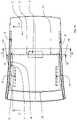
- Fig. 1B the open roof system is shown in a plan view.
- the shape of the panel 3 is tapered, whereby the frontal part of the panel 3 is larger seen in a transversal direction of the vehicle and the rear part is smaller in transversal direction.
- the lateral side edges 8, 8' of the panel 3 follow a curved line.
- the lateral side edges 8, 8' of the roof opening 2 are parallel to the same curved lines of the panel 3.
- the roof members 6, 6' left and right follow in parallel the curvature of the lateral side edges 8, 8' of the panel 3.
- the panel 3 In case the open roof system is a pop-up roof the panel 3 only needs to be moved between a closed and a tilt-position, where by in the tilt-position, the panel 3 is lifted at its rear edge 22 a certain distance.
- the tapered shape of the panel 3 in such case, allows the panel 3 to be tilted at its rear edge 22, without being jammed between the roof members 6, 6'.
- the open roof system is a top slider roof system (not shown in the drawings)
- the panel 3 also may be positioned into a tilt-position. However, because of the additional function of sliding the panel 3 to the rear, over the fixed roof 1, the shape of the panel 3 may not be tapered, because it would be jammed between the opposite mounted roof members 6, 6'.
- the lateral side edges 8, 8' of the panel 3 are straight and parallel to a central longitudinal plane of the vehicle. This means that in line what is described above, the lateral side edges 8, 8' of the roof opening 2 and the longitudinal shape of the roof members 6, 6' also need to be in parallel with the central longitudinal plane of the vehicle.
- Fig. 1B the mechanisms 5, 5' are shown in dotted lines.
- the mechanisms 5, 5' are connected between the stationary frame 4 and the lower side of the panel 3 and the function of the mechanisms 5, 5' are to move the panel 3 in a vertical direction or in a vertical and horizontal direction.
- the mechanisms 5, 5' may be placed in area's adjacent to both lateral side edges 8, 8' of the panel 3. It is also conceivable that the mechanism 5, 5' is placed in a central area adjacent to the rear edge 22 of the panel.
- the open roof system shown in Fig. 1B has only one panel 3 and the rear part of the fixed roof 1 is part of the steel body of the vehicle.
- the open roof system is equipped with more than one panel 3, whereby a second or a multitude of panels are positioned adjacent in rearward direction of the first movable panel 3.
- a front header plate is shown, this front header plate usually is not movable, however it is conceivable that the front header plate is part of a movable wind deflector.
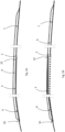
- Figs. 2A and 2B a sectional view is shown of the panel 3 and the adjacent roof member 6, 6'.
- the panel 3 is shown in its closed position, closing the roof opening 2
- Fig. 2B shows the panel 3 in tilt-position, partly opening the roof opening 2.
- the panel 3 in its tilt-position with its lateral side edges 8, 8' engages the roof member's first edge 9, 9'. This ensures that no air escapes through the seal 7 in the panels' lateral side edge 8, 8', which is advantageous in relation to the aero acoustic performance in driving conditions.
- Fig. 2A the panel 3 is shown in its closed position, closing the roof opening 2
- Fig. 2B shows the panel 3 in tilt-position, partly opening the roof opening 2.
- the panel 3 in its tilt-position with its lateral side edges 8, 8' engages the roof member's first edge 9, 9'. This ensures that no air escapes through the seal 7 in the panels' lateral side edge 8, 8', which is advantageous in relation to the aero acous
- the rear edge 22 of the panel 3 in the area of the lateral side edges 8, 8' of the panel 3, referred to as the corner edge 24, 24' of the panel 3, is flush with the top surface 12, 12' of the roof member 6, 6'.
- Figs. 3 and 4 a cross sectional view is shown along line III-III and IV-IV in fig 1B , whereby Fig. 3 shows a cross section through the fixed roof 1 and the fixing members 25 between the roof member 6, 6' and the fixed roof 1.
- Fig. 4 shows a cross section across a rear part of the panel 3 adjacent to the rear edge 22 of the panel 3.
- the panel 3 is shown in a closed position in which the roof opening 2 is closed (dotted lines) and in a tilt-position.
- the rear edge 22 of the panel 3 is substantially flush with the top surface 12, 12' of the roof member 6, 6'.
- the stationary frame 4 is shown with a secondary seal engaging the lower side of the panel 3 when the panel is in a closed position.
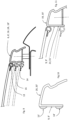
- Fig. 5A is a blown up view VA in Fig. 4 , wherein the roof member 6, 6' section is shown as a closed section. This closed section may extend longitudinally along the complete roof member 6, 6'. However, it is also conceivable that the section of the roof member 6, 6' is only closed in areas where the roof member 6, 6' has a fixing member 25 towards the fixed roof 1.
- the stationary frame 4 is shown and in this embodiment the frame 4 extends underneath the roof member 6, 6' and may support the roof member 6, 6' along the areas where the roof member 6, 6' is not supported by its fixing members 25.
- the stationary frame 4 maybe glued to the fixed roof 1 as is known in the art, but it is also conceivable that it is screwed to the body.
- the stationary frame 4 may be made of plastic (either reinforced or not) or steel, it can be made of one part or it can be made of multiple parts.
- the roof member 6, 6' in this embodiment comprises a first and a second protrusion 13,13';14, 14', protruding out of its first edge 9, 9'.
- the first protrusion 13, 13' is created at the top surface of the first edge 9, 9' and ensures that the seal 7 on the panel 3, when the panel 3 is in its tilt-position, is in an air tight engagement with the roof member 6, 6'.
- the second protrusion 14, 14' is created at the bottom surface of the first edge 9, 9' of the roof member 6, 6' to ensure that the seal 7 of the panel 3 is in an airtight engagement with the roof member 6, 6' when the panel 3 is in a closed position.
- Fig. 5B a further blown up drawing, the seal 7 is drawn through the first protrusion 13, 13' to shown how much the seal 7 will actually be deformed by the protrusion.
- the seal 7, which is typically a bulb seal, in the tilted position of the panel 3, is pressed in by the first protrusion 13, 13' by a certain depth.
- the depth of the deformation or pressing of the seal 7 is an important feature and is required for the air tightness in driving conditions. So the protrusion height H determines the pressing depth of the seal 7 and therewith the airtight sealing.
- Fig. 6 shows a sectional view across the open roof system showing another embodiment of the roof member 16, 16'.
- the roof member 16, 16' and the stationary frame 4 are integrated to one part.
- This embodiment may be advantageous in relation to the water management of the open roof system. Since the roof member 16, 16' and stationary frame 4, in this embodiment, do not have any gaps between them. The water in the so-called wet area may not leak through small gaps between the roof member 16, 16' and the stationary frame 4. As a result, countermeasures for water tightness between these parts may be omitted.
- Fig. 7 shows a sectional view across the open roof system showing another embodiment of the stationary frame 17 whereby the stationary frame 17 comprises a closing edge 23 (i.e. a second protrusion) to which the panel 3 with the seal 7 may be in airtight engagement when the panel 3 is in its closed position.
- a closing edge 23 i.e. a second protrusion
- Fig. 8 shows a cross section in a longitudinal direction by which another embodiment of the roof member 18, 18' is shown.
- the longitudinal shape of the roof member 18, 18' along its length from the front to the rear is made such that the roof member top surface 12, 12' is flush with surface of the panel 3 in the lateral side area of the panel 3 all along the longitudinal length of the panel 3.
- Fig. 9 shows a cross sectional view of the open roof system whereby the roof member 6, 6' is equipped with three protrusions.
- the first protrusion 13, 13' is at the upper end of the first edge 9, 9' of the roof member 6, 6' and the seal 7 is engaged in by this protrusion when the panel 3 is in a tilt-position, wherein the opening between the rear edge 22 of the panel 3 and the rear edge of the roof opening 2 is at its maximum.
- a second protrusion 14, 14' used for sealing the panel 3 in the closed position of the panel 3.
- Fig. 10 shows an embodiment of the roof member 20, 20' whereby the protrusions 13, 13';14, 14' are made of another material than the usual material of the roof member 6, 6'.
- These protrusions 13, 13';14, 14' may be made of Polyurethane (PU) or glass fibre reinforced Polypropylene (PP/GF) or Polyamide (PA) or Polyoxymethylene(POM) or similar materials of the same respective family of materials, whereby these materials may be connected to the base part of the roof member 20, 20' by either of gluing, welding or by being form fitted by means of extruded shapes into openings in the first edges 9,9' of the roof members 20, 20' .
- PU Polyurethane
- PP/GF Polypropylene
- PA Polyamide
- POM Polyoxymethylene
- Fig. 11 shows an embodiment whereby the roof member 19, 19' is equipped with a first protrusion 21, 21' which extends over the whole surface of the first edge 9, 9' of the roof member 19, 19'.
- the interference of the seal 7 and the first protrusion 21, 21' in this embodiment is likewise within the range H indicated in this document previously.
Landscapes
- Engineering & Computer Science (AREA)
- Mechanical Engineering (AREA)
- Seal Device For Vehicle (AREA)
- Body Structure For Vehicles (AREA)
Abstract
Description
- The invention relates to an open roof system for a vehicle, and a vehicle comprising such open roof system.
- An open roof system is well known. For instance, an open roof system which comprises a movable panel, which may be partly opening a roof opening and closing such roof opening. Such panel may be positioned in a so called "tilt" position in which the panel is lifted at its rear end upwardly but the panel at its front edge is still in an airtight engagement via the seal with the edge of the roof opening. Further in this document a panel, partly opening a roof opening in a manner as described in the previous sentence, is referred to as being in a tilt-position. An open roof system having such a panel capable of moving only to such tilt-position is usually referred to as a "pop-up" roof system, which reference is used further in this document. Other well-known open roof systems have a panel which may move in such a way that apart from the tilt-position of the panel, a further opening of the roof opening is possible by sliding the panel to the rear either above the surface of the fixed roof of the vehicle, the so called "Top slider" roof systems, or sliding below the fixed roof surface, the so called "Tilt-Vent-Slider" or "TVS" roof systems. Both of these references are used further in this document. Each of these prior art roof systems may have a tilt-position of the movable panel, which is usually the front panel of the open roof system.
- It is also known that vehicles may comprise roof rails connected on to the lateral edges of the fixed roof of the vehicle. Such roof rails hereunder referred to as roof members may be used to connect transvers placed roof racks for instance for use of carrying luggage or sport utility devices.
- In the prior art, it is known that vehicles having an open roof system may also have roof members. In such cases the lateral edges of the roof opening and therewith the lateral edges of the panel of the open roof system are positioned at a certain distance away from the roof members. The head space available for the occupants inside the vehicle is compromised by the stationary frame of the open roof system. The gap between the lateral side edge of the panel and the lateral edge of the roof opening in a tilt-position of the panel may cause considerable aero-acoustic noises under driving conditions of the vehicle.
- It is an object of the present invention to provide an open roof system for a vehicle having an improved headspace for the occupants and an improved aero-acoustic performance when the panel of the open roof construction is in a tilt-position.
- This object is achieved in an open roof system for a vehicle according to claim 1 wherein the open roof system comprises a fixed roof having a roof opening, a semi-transparent panel for closing and at least partly opening the roof opening, a stationary frame fixedly attached to the fixed roof, at least one mechanism attached between the panel and the stationary frame for moving the panel and a roof member protruding from the fixed roof in an upward direction, the roof member being attached at least partly to the fixed roof, the panel comprising a seal connected at least along the front edge and both lateral side edges of the panel, wherein the seal is in an air tight engagement with at least a part of a first edge of the roof member in a tilt-position of the panel in which the roof opening is partly open, such that aero-acoustic noises are at least reduced in said panel position. The roof member is usually placed on the fixed roof, on top of the joints of the different vehicle body parts. More precisely on top of the joint between the roof body panel and the side body part. The lateral edge of the roof opening and therewith the lateral edge of the panel is positioned adjacent to the roof member. This allows the panel comprising the seal, to be engaged with the roof member at least when the panel is in the tilt-position. This engagement is an airtight engagement such that no air leaks through the seal in the lateral areas of the panel. This reduces the aero-acoustic noises coming from the lateral edges of the panel in the tilt-position. Compared with the prior art, the increased width of the panel, having the lateral edges of the panel adjacent to the roof member, the stationary frame of the open roof construction connected to the fixed roof on the inside of the vehicle may be positioned sideways in a lateral direction outwards. Due to this the headspace of the occupants in the front and the rear of the vehicle increases because of the stationary frame being positioned more outwardly compared to the prior art. This is especially advantageous in electric vehicles whereby the headspace is compromised because of the occupant seats being positioned at a higher level in the vehicle, to allow the battery package to be stored underneath the level of the seat rails.
- In another embodiment of the invention the airtight seal engagement with the first edge of the roof member is in a position of the panel in which the roof opening is closed. Hereinafter this position is referred to as the closed position of the panel. The roof member, at the lower part of the first edge forms a closing surface for the seal of the panel, when the panel is in a partly open or tilt-position. It may be advantageous to have the closing surface (i.e. a protrusion) for the panel in its closed position and in its tilt-position, in the same part and even in the same surface. In this way tolerances between panel and seal on one side may be less critical towards the roof member and its protrusions.
- In another aspect of the invention, in the tilt-position of the panel, in which the roof opening is partly open, the seal of the panel is in an airtight engagement with a front edge of the roof opening and a rear edge of the panel is above a plane defined by the roof opening in the fixed roof. In such position of the panel both lateral side edges are in airtight engagement with the first edge of the respective roof members, and also the front edge of panel is in an airtight engagement with the front edge of the roof opening. This adds to the suppression of aero-acoustic noises coming from the panel in a tilt-position.
- According to another aspect of the invention the panel comprises a top surface, which surface is flush with the surface of the fixed roof when the roof opening is closed by the panel and wherein the top surface of the panel is substantially flush with a roof member top surface, at least along a part of the longitudinal length of the roof member, in a tilt-position of the panel in which the roof opening is partly open. Apart from the previously mentioned advantageous aspects of improved head space and improved aero-acoustic performance, also the esthetical aspect is one of importance. The roof member usually has a cross section which is substantially the same along its whole length. Only the front end and the rear end of the roof member may have a gradually changing section. In this type of roof member, it is possible to have the front connections of the transvers roof racks relatively in the frontal part of the roof members and the rear connections of the transverse roof racks in the rear part of the roof member. It is however also conceivable that the roof member has a frontal part such that its section gradually grows from its front roughly towards the area where the panel has its rear edge. The height of the roof member and therewith the roof member top surface along its frontal part equals the height of the panel when the panel is in a tilt-position. In such position of the panel, the styling of the open roof system may be aesthetically improved.
- According yet another embodiment, the roof member is partly attached to the fixed roof and partly to the stationary frame. It may be conceivable to have the roof members integrated to the stationary frame of the open roof system. In such an embodiment the roof members may be part of the delivery content of the open roof construction towards the end customer.
- According another aspect of the invention, the first edge of the roof member comprises at least a first protrusion in a lateral inward direction of the vehicle, with which the seal of the panel is in an airtight engagement, when the panel is in a tilt-position in which the roof opening is partly open. The first edge of the roof member may comprise a second protrusion in a lateral inward direction of the vehicle, with which the seal of the panel is in an airtight engagement when the panel is in a closed position in which the roof opening is closed. The first edge of the roof member may comprise a third protrusion in a lateral inward direction of the vehicle, with which the seal of the panel is in an airtight engagement when the panel is in an intermediate tilt-position in which the roof opening is partly open having a reduced opening.
- The first edge may comprise a first protrusion, or a first and second protrusion or even a first, second and protrusion oriented to the longitudinal middle of the vehicle. The respective protrusions are required to have an engagement surface for the seal such that the seal is pressed in enough to give an airtight engagement. The third protrusion may be positioned on the first edge of the roof member in between the first and the second protrusion. The third protrusion may be used in case the panel is required to have an intermediate tilt-position also referred to as a partly open position.
- According to yet another aspect of the invention, the seal may move freely along the first edge of the roof member in areas adjacent the first, second and third protrusions when the panel moves from a closed position where it closes the roof opening to a tilt-position when the roof opening is partly open and vice versa.
- Whereas the seal must have an airtight engagement with the protrusions when the panel is in a tilt-position or closed position. When the panel moves in between the closed and the tilt-positions, the seal may not be obstructed such that the movement induces noises, such as for instance squeak noises coming from the seal. As such the seal must be able to move freely between the closed position and the tilt-position.
- According to yet another embodiment of the invention the roof member comprising the first edge having a full surface protrusion in a lateral inward direction of the vehicle, whereby the protrusion extends along substantially the whole first edge.
- It may be conceivable that with a seal of a particular material having a low coefficient of friction and/or the use of a slip coat on the surface of the seal the phenomena of squeaking is avoided when the seal is pressed and moved at the same time. In such case the first edge of the roof member may be a full surface protrusion, whereby the panel and therewith the seal moves between the closed position in which the panel closes the roof opening and the tilt-position in which the panel partly opens the roof opening.
- According to another aspect of the invention the protrusions have a height H above the surface of the first edge in a range of 0,4 mm. to 9 mm. and more in particular in a range of 1,2 mm. to 3 mm. The seal in an airtight engagement with a protrusion must be pressed by a certain depth. This depth is created by the position of the seal on a lateral edge of the panel on one side and the protrusion on the first edge on the opposite side. Due to the various tolerance stacks that may occur in the various embodiments of the invention and the requirement of having an airtight sealing between seal and the roof member, the protrusions need to have a certain height H in above mentioned ranges.
- The roof member may comprise protrusions which are made of a material different to that of the roof member and wherein the protrusions are made of Polyurethane (PU) or glass fibre reinforced Polypropylene (PP/GF) or Polyamide (PA) or Polyoxymethylene(POM) or similar materials of the same respective family of materials.
- It may be conceivable to make the protrusions of different material then that of the roof members. The roof member is usually made of aluminium for instance by an extrusion process, or a casting process. And coated with coating. In case the protrusions are made of another material, such as the materials indicated above, specific characteristics may be used of this material for instance in relation to a low coefficient of friction, low wear of the coating, avoidance of the phenomena of slip-stick, etc.
- According to yet another embodiment in a closed position of the panel in which the roof opening is closed, the seal engagement is with a closing edge of the stationary frame. It may be conceivable that the second protrusion, the protrusion required to have an airtight engagement with the seal when the panel closes the roof opening is not formed on the first edge of the roof member but by means of the closing edge formed on the stationary frame. This may be advantageous to control the water management of the open roof constructions.
- The invention also includes vehicle having an open roof system as described above.
- Further details and advantages of the invention follow from the description below with reference to the drawings in which:
-
Fig. 1A is a schematic perspective view of a vehicle roof having an open roof system according to the invention. -
Fig. 1B is a plan view of the open roof system and part of the fixed roof. -
Fig. 2A and 2B are sectional views across the open roof system according to line II-II inFig. 1B , wherebyFig.2A shows the panel in a closed position andFig. 2B shows the panel in a tilt-position. -
Fig. 3 is a sectional view of the open roof system according to line III-III inFig. 1B . -
Fig. 4 is a sectional view of the open roof system according to line IV-IV inFig. 1B . -
Fig. 5A is a detailed view of area VA in Fig. IV. -
Fig. 5B is a detailed view of area VB inFig. 5A -
Fig. 6 is a detailed sectional view similar asFig. 5A , of a second embodiment of the invention. -
Fig. 7 is a detailed sectional view similar asFig. 5A , of a third embodiment of the invention. -
Fig. 8 is a sectional view similar asFigs. 2A or 2B of a fourth embodiment in which the panel is drawn in two positions. -
Fig. 9 is a sectional view similar as inFig. 5A of a fifth embodiment of the invention. -
Fig. 10 is a sectional view similar as inFig. 5A of a sixth embodiment of the invention. -
Fig. 11 is a sectional view similar as inFig. 5A of a seventh embodiment of the invention. - Referring to
Fig. 1A a vehicle roof is shown having an open roof assembly, aroof opening 2 in afixed roof 1, a pair ofroof members 6, 6'. The open roof system shown is a so-called pop-up roof whereby thepanel 3 of the open roof system is capable of being moved from a position whereby thepanel 3 closes the roof opening 2 (closed position) to a position wherein thepanel 3 at least partly opens the roof opening 2 (tilt-position). InFig.1 thepanel 3 is drawn in its closed position, however thepanel 3 may be lifted by means of amechanism 5, 5' connected between thestationary frame 4 and thepanel 3, to a tilt-position, such that an opening is created between therear edge 22 of thepanel 3 and the edge of theroof opening 2. Further inFig. 1 a pair ofroof members 6, 6' is shown on both lateral side edges 8, 8' of the fixedroof 1. Theroof members 6, 6' extend in a longitudinal direction from the front of the fixedroof 1 towards the rear of the fixedroof 1 and theroof members 6, 6' are fixed to the body on several places by means of fixingmembers 25. - In the tilt-position the
panel 3 is in engagement with the edge of theroof opening 2 at thefront edge 10 by means of theseal 7. The lateral side edges 8, 8' of thepanel 3 are also in engagement with theroof members 6, 6', via theseal 7, such that no air leakage may occur in that area. In this tilt-position of thepanel 3, air inside the vehicle may flow to the environment or vice versa. It is also conceivable that another type of open roof system is used in relation to the invention, for instance a top slider roof system may be used whereby thepanel 3 of this type of roof, not only may be positioned in a tilt-position, but also may slide to the rear above the surface of the fixedroof 1 by means ofmechanisms 5, 5' that are connected between thestationary frame 4 and thepanel 3. In case such a top slider roof is used in the vehicle, the airtight engagement of theseal 7 on thepanel 3 towards theroof member 6, 6' is only favourable in the tilt-position of thepanel 3 and not when thepanel 3 is in a fully open position, whereby thepanel 3 is slid over the fixedroof 1 to the rear. - Referring to
Fig. 1B the open roof system is shown in a plan view. The shape of thepanel 3 is tapered, whereby the frontal part of thepanel 3 is larger seen in a transversal direction of the vehicle and the rear part is smaller in transversal direction. As can be seen fromFig. 1B , the lateral side edges 8, 8' of thepanel 3 follow a curved line. The lateral side edges 8, 8' of theroof opening 2 are parallel to the same curved lines of thepanel 3. And also theroof members 6, 6' left and right follow in parallel the curvature of the lateral side edges 8, 8' of thepanel 3. In case the open roof system is a pop-up roof thepanel 3 only needs to be moved between a closed and a tilt-position, where by in the tilt-position, thepanel 3 is lifted at its rear edge 22 a certain distance. The tapered shape of thepanel 3 in such case, allows thepanel 3 to be tilted at itsrear edge 22, without being jammed between theroof members 6, 6'. In case the open roof system is a top slider roof system (not shown in the drawings), thepanel 3 also may be positioned into a tilt-position. However, because of the additional function of sliding thepanel 3 to the rear, over the fixedroof 1, the shape of thepanel 3 may not be tapered, because it would be jammed between the opposite mountedroof members 6, 6'. So in such case that a top slider roof system is used, it is required that the lateral side edges 8, 8' of thepanel 3 are straight and parallel to a central longitudinal plane of the vehicle. This means that in line what is described above, the lateral side edges 8, 8' of theroof opening 2 and the longitudinal shape of theroof members 6, 6' also need to be in parallel with the central longitudinal plane of the vehicle. - In
Fig. 1B themechanisms 5, 5' are shown in dotted lines. Generally, in all types of open roof systems themechanisms 5, 5' are connected between thestationary frame 4 and the lower side of thepanel 3 and the function of themechanisms 5, 5' are to move thepanel 3 in a vertical direction or in a vertical and horizontal direction. In case a Pop-up roof is used as an open roof system, themechanisms 5, 5' may be placed in area's adjacent to both lateral side edges 8, 8' of thepanel 3. It is also conceivable that themechanism 5, 5' is placed in a central area adjacent to therear edge 22 of the panel. The open roof system shown inFig. 1B has only onepanel 3 and the rear part of the fixedroof 1 is part of the steel body of the vehicle. It is however conceivable that the open roof system is equipped with more than onepanel 3, whereby a second or a multitude of panels are positioned adjacent in rearward direction of the firstmovable panel 3. Also it is shown that in front of the movable panel 3 a front header plate is shown, this front header plate usually is not movable, however it is conceivable that the front header plate is part of a movable wind deflector. - In
Figs. 2A and 2B a sectional view is shown of thepanel 3 and theadjacent roof member 6, 6'. InFig. 2A thepanel 3 is shown in its closed position, closing theroof opening 2, andFig. 2B shows thepanel 3 in tilt-position, partly opening theroof opening 2. Thepanel 3 in its tilt-position with its lateral side edges 8, 8' engages the roof member'sfirst edge 9, 9'. This ensures that no air escapes through theseal 7 in the panels'lateral side edge 8, 8', which is advantageous in relation to the aero acoustic performance in driving conditions. InFig. 2B therear edge 22 of thepanel 3 in the area of the lateral side edges 8, 8' of thepanel 3, referred to as thecorner edge 24, 24' of thepanel 3, is flush with thetop surface 12, 12' of theroof member 6, 6'. This gives an optimal esthetical impression of the open roof system in a tilt-position. It is however conceivable that thecorner edge 24, 24' of thepanel 3 protrudes above thetop surface 12, 12' of theroof member 6, 6'. This could be required when the rear opening between therear edge 22 of thepanel 3 and the rear edge of theroof opening 2 needs to be designed to be enlarged for ventilation purposes. - In
Figs. 3 and 4 a cross sectional view is shown along line III-III and IV-IV infig 1B , wherebyFig. 3 shows a cross section through the fixedroof 1 and the fixingmembers 25 between theroof member 6, 6' and the fixedroof 1.Fig. 4 shows a cross section across a rear part of thepanel 3 adjacent to therear edge 22 of thepanel 3. Here thepanel 3 is shown in a closed position in which theroof opening 2 is closed (dotted lines) and in a tilt-position. In thisFig. 4 it is clearly shown that therear edge 22 of thepanel 3 is substantially flush with thetop surface 12, 12' of theroof member 6, 6'. Also thestationary frame 4 is shown with a secondary seal engaging the lower side of thepanel 3 when the panel is in a closed position. -
Fig. 5A is a blown up view VA inFig. 4 , wherein theroof member 6, 6' section is shown as a closed section. This closed section may extend longitudinally along thecomplete roof member 6, 6'. However, it is also conceivable that the section of theroof member 6, 6' is only closed in areas where theroof member 6, 6' has a fixingmember 25 towards the fixedroof 1. Thestationary frame 4 is shown and in this embodiment theframe 4 extends underneath theroof member 6, 6' and may support theroof member 6, 6' along the areas where theroof member 6, 6' is not supported by its fixingmembers 25. - The
stationary frame 4 maybe glued to the fixedroof 1 as is known in the art, but it is also conceivable that it is screwed to the body. Thestationary frame 4 may be made of plastic (either reinforced or not) or steel, it can be made of one part or it can be made of multiple parts. Theroof member 6, 6' in this embodiment comprises a first and asecond protrusion 13,13';14, 14', protruding out of itsfirst edge 9, 9'. Thefirst protrusion 13, 13' is created at the top surface of thefirst edge 9, 9' and ensures that theseal 7 on thepanel 3, when thepanel 3 is in its tilt-position, is in an air tight engagement with theroof member 6, 6'. Similarly, thesecond protrusion 14, 14' is created at the bottom surface of thefirst edge 9, 9' of theroof member 6, 6' to ensure that theseal 7 of thepanel 3 is in an airtight engagement with theroof member 6, 6' when thepanel 3 is in a closed position. - In
Fig. 5B a further blown up drawing, theseal 7 is drawn through thefirst protrusion 13, 13' to shown how much theseal 7 will actually be deformed by the protrusion. Here theseal 7, which is typically a bulb seal, in the tilted position of thepanel 3, is pressed in by thefirst protrusion 13, 13' by a certain depth. The depth of the deformation or pressing of theseal 7 is an important feature and is required for the air tightness in driving conditions. So the protrusion height H determines the pressing depth of theseal 7 and therewith the airtight sealing. -
Fig. 6 shows a sectional view across the open roof system showing another embodiment of theroof member 16, 16'. Theroof member 16, 16' and thestationary frame 4 are integrated to one part. This embodiment may be advantageous in relation to the water management of the open roof system. Since theroof member 16, 16' andstationary frame 4, in this embodiment, do not have any gaps between them. The water in the so-called wet area may not leak through small gaps between theroof member 16, 16' and thestationary frame 4. As a result, countermeasures for water tightness between these parts may be omitted. -
Fig. 7 shows a sectional view across the open roof system showing another embodiment of thestationary frame 17 whereby thestationary frame 17 comprises a closing edge 23 (i.e. a second protrusion) to which thepanel 3 with theseal 7 may be in airtight engagement when thepanel 3 is in its closed position. -
Fig. 8 shows a cross section in a longitudinal direction by which another embodiment of theroof member 18, 18' is shown. In this embodiment the longitudinal shape of theroof member 18, 18' along its length from the front to the rear is made such that the roofmember top surface 12, 12' is flush with surface of thepanel 3 in the lateral side area of thepanel 3 all along the longitudinal length of thepanel 3. -
Fig. 9 shows a cross sectional view of the open roof system whereby theroof member 6, 6' is equipped with three protrusions. Thefirst protrusion 13, 13' is at the upper end of thefirst edge 9, 9' of theroof member 6, 6' and theseal 7 is engaged in by this protrusion when thepanel 3 is in a tilt-position, wherein the opening between therear edge 22 of thepanel 3 and the rear edge of theroof opening 2 is at its maximum. And asecond protrusion 14, 14' used for sealing thepanel 3 in the closed position of thepanel 3. And further athird protrusion 15, 15' in between the first and thesecond protrusions 13, 13'; 14, 14' for sealing thepanel 3 in a maximum size tilt-position and a closed position. -
Fig. 10 shows an embodiment of the roof member 20, 20' whereby theprotrusions 13, 13';14, 14' are made of another material than the usual material of theroof member 6, 6'. Theseprotrusions 13, 13';14, 14' may be made of Polyurethane (PU) or glass fibre reinforced Polypropylene (PP/GF) or Polyamide (PA) or Polyoxymethylene(POM) or similar materials of the same respective family of materials, whereby these materials may be connected to the base part of the roof member 20, 20' by either of gluing, welding or by being form fitted by means of extruded shapes into openings in thefirst edges 9,9' of the roof members 20, 20' . -
Fig. 11 shows an embodiment whereby the roof member 19, 19' is equipped with a first protrusion 21, 21' which extends over the whole surface of thefirst edge 9, 9' of the roof member 19, 19'. This means that theseal 7 is not only pressed in both of the closed positions and tilt-positions of thepanel 7 but also when moving thepanel 7 in between these two positions. The interference of theseal 7 and the first protrusion 21, 21' in this embodiment is likewise within the range H indicated in this document previously. - Aspects of the invention are not limited to the embodiments described before which may be varied widely within the scope of the invention as defined in the appended claims.
Claims (14)
- Open roof system for a vehicle comprising a fixed roof (1) having a roof opening (2), comprising a semi-transparent panel (3) for closing and at least partly opening said roof opening (2), a stationary frame (4, 17) configured to be fixedly attached to the fixed roof (1), at least one mechanism (5, 5', 5") provided between the panel (3) and the stationary frame (4, 17) for moving the panel (3), and a roof member (6, 6'; 16; 18, 18'; 19, 19'; 20, 20') protruding from the fixed roof (1) in an upward direction, said roof member being attached at least partly to the fixed roof (1), said panel (3) comprising a seal (7) connected at least along the front edge (10) and both lateral side edges (8, 8') of the panel (3), characterized in that the seal (7) is in an airtight engagement with at least a part of a first edge (9, 9') of the roof member (6, 6'; 16; 18, 18'; 19, 19'; 20, 20') in a tilt-position of the panel (3) in which the roof opening (2) is partly open, such that aero-acoustic noises are at least reduced in said tilt-position of the panel.
- The open roof system according to claim 1, wherein the airtight seal engagement with the first edge (9, 9') of the roof member (6, 6'; 16; 18, 18'; 19, 19'; 20, 20') is in a position of the panel (3) in which the roof opening (2) is closed.
- The open roof system according to claim 1, wherein in the tilt-position of the panel (3) in which the roof opening (2) is partly open, the seal (3) of the panel (3) is in an airtight engagement with a front edge (10) of the roof opening (2) and a rear edge (22) of the panel (3) is above a plane defined by the roof opening (2) in the fixed roof (1).
- The open roof system according to claim 1, wherein the panel (3) comprises a top surface (11), which surface is flush with the surface of the fixed roof (1) when the roof opening (2) is closed by the panel (3) and wherein the top surface (11) of the panel (3) is substantially flush with a roof member top surface (12, 12'), at least along a part of the longitudinal length of the roof member (6, 6'), in a tilt-position of the panel (3) in which the roof opening (2) is partly open.
- The open roof system according to claim 1, wherein the roof member (16) is partly attachable to the fixed roof (1) and partly attached to the stationary frame (4).
- The open roof system according to any of the previous claims, wherein the first edge (9, 9') of the roof member (6, 6'; 16; 18, 18'; 20, 20') comprises at least a first protrusion (13, 13') in a lateral inward direction of the vehicle, with which the seal (7) of the panel (3) is in an airtight engagement, when the panel (3) is in a tilt-position in which the roof opening (2) is partly open.
- The open roof system according to claim 6, wherein the first edge (9, 9') of the roof member (6, 6'; 16; 18, 18'; 20, 20') comprises a second protrusion (14) in a lateral inward direction of the vehicle, with which the seal (7) of the panel (3) is in an airtight engagement when the panel (3) is in a closed position in which the roof opening (2) is closed.
- The open roof system according to claim 6, wherein the first edge (9, 9') of the roof member (6, 6'; 18, 18'; 20, 20') comprises a third protrusion (15, 15') in a lateral inward direction of the vehicle, with which the seal (7) of the panel (3) is in an airtight engagement when the panel (3) is in an intermediate tilt-position in which the roof opening (2) is partly open having a reduced opening.
- The open roof system according any of claims 6, 7 or 8, wherein the seal (7) may move freely along the first edge (9, 9') of the roof member (6, 6'; 18, 18'; 20, 20') in areas adjacent the first, second and third protrusions (13, 13'; 14, 14'; 15, 15') when the panel (3) moves from a closed position where it closes the roof opening (2) to a tilt-position when the roof opening (2) is partly open and vice versa.
- The open roof system according to claim 1, wherein the roof member (19, 19') comprising the first edge (9, 9') has a full surface protrusion (21, 21') in a lateral inward direction of the vehicle, whereby the protrusion extends along substantially the whole first edge (9, 9').
- The open roof system according to any of claims 6, 7, 8 or 10, wherein the protrusions (13, 13'; 14, 14'; 15, 15'; 21, 21') have a height H above the surface of the first edge in a range of 0,4 mm. to 9 mm. and more in particular in a range of 1,2 mm. to 3 mm.
- The open roof system according to any of claims 6, 7, 8 or 10, wherein the roof member (20, 20') comprising protrusions (13, 13'; 14, 14'; 15, 15'; 21, 21) which are made of a material different to that of the roof member (6, 6'; 16, 18, 18'; 19, 19') and wherein the protrusions are made of Polyurethane (PU) or glass fibre reinforced Polypropylene (PP/GF) or Polyamide (PA) or Polyoxymethylene(POM) or similar materials of the same respective family of materials.
- The open roof system according to claim 1, wherein in a closed position of the panel (3) in which the roof opening (2) is closed, the seal engagement is with a closing edge (23, 23') of the stationary frame (4).
- A vehicle having an open roof system, comprising a fixed roof (1) having a roof opening (2), a semi-transparent panel (3) for closing and at least partly opening said roof opening (2), a stationary frame (4, 17) fixedly attached to the fixed roof (1), at least one mechanism (5, 5', 5") provided between the panel (3) and the stationary frame (4, 17) for moving the panel (3), and a roof member (6, 6';18, 18'; 19, 19'; 20, 20') protruding from the fixed roof (1) in an upward direction, said roof member being attachable at least partly to the fixed roof (1), said panel (3) comprising a seal (7) connected at least along the front edge (10) and both lateral side edges (8, 8') of the panel (3), characterized in that the seal (7) is in an air tight engagement with at least a part of a first edge (9, 9') of the roof member in a tilt-position of the panel (3) in which the roof opening (2) is partly open, such that aero-acoustic noises are at least reduced in said tilt-position of the panel.
Priority Applications (2)
| Application Number | Priority Date | Filing Date | Title |
|---|---|---|---|
| EP21189136.1A EP4129724B1 (en) | 2021-08-02 | 2021-08-02 | Tilted panel touching roof rails for better aeroacoustics |
| CN202210903061.3A CN115701392A (en) | 2021-08-02 | 2022-07-29 | Tilting panel for contacting roof rail for better aerodynamic acoustic effect |
Applications Claiming Priority (1)
| Application Number | Priority Date | Filing Date | Title |
|---|---|---|---|
| EP21189136.1A EP4129724B1 (en) | 2021-08-02 | 2021-08-02 | Tilted panel touching roof rails for better aeroacoustics |
Publications (2)
| Publication Number | Publication Date |
|---|---|
| EP4129724A1 true EP4129724A1 (en) | 2023-02-08 |
| EP4129724B1 EP4129724B1 (en) | 2024-06-05 |
Family
ID=77179899
Family Applications (1)
| Application Number | Title | Priority Date | Filing Date |
|---|---|---|---|
| EP21189136.1A Active EP4129724B1 (en) | 2021-08-02 | 2021-08-02 | Tilted panel touching roof rails for better aeroacoustics |
Country Status (2)
| Country | Link |
|---|---|
| EP (1) | EP4129724B1 (en) |
| CN (1) | CN115701392A (en) |
Citations (3)
| Publication number | Priority date | Publication date | Assignee | Title |
|---|---|---|---|---|
| DE4142265C1 (en) * | 1991-12-20 | 1992-12-17 | Webasto Ag Fahrzeugtechnik, 8035 Stockdorf, De | Car sun roof with rigid lid(s) - has roof railing with side screens along its length in section protruding beyond roof skin in sun roof open position |
| US5362122A (en) * | 1992-08-19 | 1994-11-08 | Webasto Karosseriesysteme Gmbh | Vehicle roof |
| DE102013218387A1 (en) * | 2013-09-13 | 2015-03-19 | Volkswagen Aktiengesellschaft | motor vehicle |
-
2021
- 2021-08-02 EP EP21189136.1A patent/EP4129724B1/en active Active
-
2022
- 2022-07-29 CN CN202210903061.3A patent/CN115701392A/en active Pending
Patent Citations (3)
| Publication number | Priority date | Publication date | Assignee | Title |
|---|---|---|---|---|
| DE4142265C1 (en) * | 1991-12-20 | 1992-12-17 | Webasto Ag Fahrzeugtechnik, 8035 Stockdorf, De | Car sun roof with rigid lid(s) - has roof railing with side screens along its length in section protruding beyond roof skin in sun roof open position |
| US5362122A (en) * | 1992-08-19 | 1994-11-08 | Webasto Karosseriesysteme Gmbh | Vehicle roof |
| DE102013218387A1 (en) * | 2013-09-13 | 2015-03-19 | Volkswagen Aktiengesellschaft | motor vehicle |
Also Published As
| Publication number | Publication date |
|---|---|
| EP4129724B1 (en) | 2024-06-05 |
| CN115701392A (en) | 2023-02-10 |
Similar Documents
| Publication | Publication Date | Title |
|---|---|---|
| US11241945B2 (en) | Automobile door glass run | |
| US4089134A (en) | Window guide mechanism for a tight air seal of a vehicle window assembly | |
| CN102991314B (en) | For assembling the method for concordant glass assembly with glass | |
| JP6371269B2 (en) | Vehicle door glass lifting structure | |
| EP1862343B1 (en) | Glass run channel of automotive door window | |
| JP6700900B2 (en) | Sealing material for automobile doors | |
| US8453383B2 (en) | Adjustable glass clamp for cable drive window regulators | |
| US9845001B1 (en) | Glass run for automobile door | |
| JP6715016B2 (en) | Automotive door seal structure | |
| US10112468B2 (en) | Glass run for automobile door | |
| US7172240B1 (en) | One-piece wind deflector for spanning multiple-paned vehicle window | |
| US20140319882A1 (en) | Side Panel of a Vehicle Roof that can be Opened | |
| EP3219530B1 (en) | Open roof construction for a vehicle | |
| CN108116202B (en) | Mounting structure of glass run for automobile door | |
| US6974183B2 (en) | Openable motor vehicle roof | |
| US8177294B2 (en) | Vehicle roof | |
| US6932415B1 (en) | Door sealing assembly | |
| EP4129724B1 (en) | Tilted panel touching roof rails for better aeroacoustics | |
| US7871120B2 (en) | Four-door motor vehicle having a door sealing system for frameless doors | |
| US20200317028A1 (en) | Vehicle passenger compartment vent structure | |
| US8522481B2 (en) | Glass run mounting assembly for a vehicle door | |
| US20250100361A1 (en) | Sealing profile strand and sealing arrangement for a sliding window | |
| EP4101669B1 (en) | Roof system having a wind deflector assembly | |
| EP1886859B1 (en) | Sealing structure of back door opening | |
| JP4271786B2 (en) | Sunroof deflector structure |
Legal Events
| Date | Code | Title | Description |
|---|---|---|---|
| PUAI | Public reference made under article 153(3) epc to a published international application that has entered the european phase |
Free format text: ORIGINAL CODE: 0009012 |
|
| STAA | Information on the status of an ep patent application or granted ep patent |
Free format text: STATUS: THE APPLICATION HAS BEEN PUBLISHED |
|
| AK | Designated contracting states |
Kind code of ref document: A1 Designated state(s): AL AT BE BG CH CY CZ DE DK EE ES FI FR GB GR HR HU IE IS IT LI LT LU LV MC MK MT NL NO PL PT RO RS SE SI SK SM TR |
|
| STAA | Information on the status of an ep patent application or granted ep patent |
Free format text: STATUS: REQUEST FOR EXAMINATION WAS MADE |
|
| 17P | Request for examination filed |
Effective date: 20230807 |
|
| RBV | Designated contracting states (corrected) |
Designated state(s): AL AT BE BG CH CY CZ DE DK EE ES FI FR GB GR HR HU IE IS IT LI LT LU LV MC MK MT NL NO PL PT RO RS SE SI SK SM TR |
|
| GRAP | Despatch of communication of intention to grant a patent |
Free format text: ORIGINAL CODE: EPIDOSNIGR1 |
|
| STAA | Information on the status of an ep patent application or granted ep patent |
Free format text: STATUS: GRANT OF PATENT IS INTENDED |
|
| RIC1 | Information provided on ipc code assigned before grant |
Ipc: B60J 7/00 20060101ALN20231222BHEP Ipc: B60R 9/05 20060101ALI20231222BHEP Ipc: B60J 10/90 20160101AFI20231222BHEP |
|
| INTG | Intention to grant announced |
Effective date: 20240131 |
|
| GRAS | Grant fee paid |
Free format text: ORIGINAL CODE: EPIDOSNIGR3 |
|
| GRAA | (expected) grant |
Free format text: ORIGINAL CODE: 0009210 |
|
| STAA | Information on the status of an ep patent application or granted ep patent |
Free format text: STATUS: THE PATENT HAS BEEN GRANTED |
|
| AK | Designated contracting states |
Kind code of ref document: B1 Designated state(s): AL AT BE BG CH CY CZ DE DK EE ES FI FR GB GR HR HU IE IS IT LI LT LU LV MC MK MT NL NO PL PT RO RS SE SI SK SM TR |
|
| REG | Reference to a national code |
Ref country code: CH Ref legal event code: EP |
|
| REG | Reference to a national code |
Ref country code: DE Ref legal event code: R096 Ref document number: 602021014009 Country of ref document: DE |
|
| REG | Reference to a national code |
Ref country code: IE Ref legal event code: FG4D |
|
| REG | Reference to a national code |
Ref country code: LT Ref legal event code: MG9D |
|
| PG25 | Lapsed in a contracting state [announced via postgrant information from national office to epo] |
Ref country code: BG Free format text: LAPSE BECAUSE OF FAILURE TO SUBMIT A TRANSLATION OF THE DESCRIPTION OR TO PAY THE FEE WITHIN THE PRESCRIBED TIME-LIMIT Effective date: 20240605 |
|
| PG25 | Lapsed in a contracting state [announced via postgrant information from national office to epo] |
Ref country code: FI Free format text: LAPSE BECAUSE OF FAILURE TO SUBMIT A TRANSLATION OF THE DESCRIPTION OR TO PAY THE FEE WITHIN THE PRESCRIBED TIME-LIMIT Effective date: 20240605 Ref country code: HR Free format text: LAPSE BECAUSE OF FAILURE TO SUBMIT A TRANSLATION OF THE DESCRIPTION OR TO PAY THE FEE WITHIN THE PRESCRIBED TIME-LIMIT Effective date: 20240605 |
|
| PG25 | Lapsed in a contracting state [announced via postgrant information from national office to epo] |
Ref country code: GR Free format text: LAPSE BECAUSE OF FAILURE TO SUBMIT A TRANSLATION OF THE DESCRIPTION OR TO PAY THE FEE WITHIN THE PRESCRIBED TIME-LIMIT Effective date: 20240906 |
|
| PG25 | Lapsed in a contracting state [announced via postgrant information from national office to epo] |
Ref country code: ES Free format text: LAPSE BECAUSE OF FAILURE TO SUBMIT A TRANSLATION OF THE DESCRIPTION OR TO PAY THE FEE WITHIN THE PRESCRIBED TIME-LIMIT Effective date: 20240605 |
|
| PG25 | Lapsed in a contracting state [announced via postgrant information from national office to epo] |
Ref country code: LV Free format text: LAPSE BECAUSE OF FAILURE TO SUBMIT A TRANSLATION OF THE DESCRIPTION OR TO PAY THE FEE WITHIN THE PRESCRIBED TIME-LIMIT Effective date: 20240605 |
|
| PG25 | Lapsed in a contracting state [announced via postgrant information from national office to epo] |
Ref country code: NO Free format text: LAPSE BECAUSE OF FAILURE TO SUBMIT A TRANSLATION OF THE DESCRIPTION OR TO PAY THE FEE WITHIN THE PRESCRIBED TIME-LIMIT Effective date: 20240905 Ref country code: LV Free format text: LAPSE BECAUSE OF FAILURE TO SUBMIT A TRANSLATION OF THE DESCRIPTION OR TO PAY THE FEE WITHIN THE PRESCRIBED TIME-LIMIT Effective date: 20240605 Ref country code: HR Free format text: LAPSE BECAUSE OF FAILURE TO SUBMIT A TRANSLATION OF THE DESCRIPTION OR TO PAY THE FEE WITHIN THE PRESCRIBED TIME-LIMIT Effective date: 20240605 Ref country code: GR Free format text: LAPSE BECAUSE OF FAILURE TO SUBMIT A TRANSLATION OF THE DESCRIPTION OR TO PAY THE FEE WITHIN THE PRESCRIBED TIME-LIMIT Effective date: 20240906 Ref country code: FI Free format text: LAPSE BECAUSE OF FAILURE TO SUBMIT A TRANSLATION OF THE DESCRIPTION OR TO PAY THE FEE WITHIN THE PRESCRIBED TIME-LIMIT Effective date: 20240605 Ref country code: ES Free format text: LAPSE BECAUSE OF FAILURE TO SUBMIT A TRANSLATION OF THE DESCRIPTION OR TO PAY THE FEE WITHIN THE PRESCRIBED TIME-LIMIT Effective date: 20240605 Ref country code: BG Free format text: LAPSE BECAUSE OF FAILURE TO SUBMIT A TRANSLATION OF THE DESCRIPTION OR TO PAY THE FEE WITHIN THE PRESCRIBED TIME-LIMIT Effective date: 20240605 Ref country code: RS Free format text: LAPSE BECAUSE OF FAILURE TO SUBMIT A TRANSLATION OF THE DESCRIPTION OR TO PAY THE FEE WITHIN THE PRESCRIBED TIME-LIMIT Effective date: 20240905 |
|
| PG25 | Lapsed in a contracting state [announced via postgrant information from national office to epo] |
Ref country code: NL Free format text: LAPSE BECAUSE OF FAILURE TO SUBMIT A TRANSLATION OF THE DESCRIPTION OR TO PAY THE FEE WITHIN THE PRESCRIBED TIME-LIMIT Effective date: 20240605 |
|
| REG | Reference to a national code |
Ref country code: AT Ref legal event code: MK05 Ref document number: 1692227 Country of ref document: AT Kind code of ref document: T Effective date: 20240605 |
|
| PG25 | Lapsed in a contracting state [announced via postgrant information from national office to epo] |
Ref country code: NL Free format text: LAPSE BECAUSE OF FAILURE TO SUBMIT A TRANSLATION OF THE DESCRIPTION OR TO PAY THE FEE WITHIN THE PRESCRIBED TIME-LIMIT Effective date: 20240605 |
|
| PG25 | Lapsed in a contracting state [announced via postgrant information from national office to epo] |
Ref country code: PT Free format text: LAPSE BECAUSE OF FAILURE TO SUBMIT A TRANSLATION OF THE DESCRIPTION OR TO PAY THE FEE WITHIN THE PRESCRIBED TIME-LIMIT Effective date: 20241007 |
|
| PG25 | Lapsed in a contracting state [announced via postgrant information from national office to epo] |
Ref country code: PT Free format text: LAPSE BECAUSE OF FAILURE TO SUBMIT A TRANSLATION OF THE DESCRIPTION OR TO PAY THE FEE WITHIN THE PRESCRIBED TIME-LIMIT Effective date: 20241007 |
|
| PG25 | Lapsed in a contracting state [announced via postgrant information from national office to epo] |
Ref country code: PL Free format text: LAPSE BECAUSE OF FAILURE TO SUBMIT A TRANSLATION OF THE DESCRIPTION OR TO PAY THE FEE WITHIN THE PRESCRIBED TIME-LIMIT Effective date: 20240605 |
|
| PG25 | Lapsed in a contracting state [announced via postgrant information from national office to epo] |
Ref country code: EE Free format text: LAPSE BECAUSE OF FAILURE TO SUBMIT A TRANSLATION OF THE DESCRIPTION OR TO PAY THE FEE WITHIN THE PRESCRIBED TIME-LIMIT Effective date: 20240605 |
|
| PG25 | Lapsed in a contracting state [announced via postgrant information from national office to epo] |
Ref country code: IS Free format text: LAPSE BECAUSE OF FAILURE TO SUBMIT A TRANSLATION OF THE DESCRIPTION OR TO PAY THE FEE WITHIN THE PRESCRIBED TIME-LIMIT Effective date: 20241005 Ref country code: AT Free format text: LAPSE BECAUSE OF FAILURE TO SUBMIT A TRANSLATION OF THE DESCRIPTION OR TO PAY THE FEE WITHIN THE PRESCRIBED TIME-LIMIT Effective date: 20240605 |
|
| PG25 | Lapsed in a contracting state [announced via postgrant information from national office to epo] |
Ref country code: CZ Free format text: LAPSE BECAUSE OF FAILURE TO SUBMIT A TRANSLATION OF THE DESCRIPTION OR TO PAY THE FEE WITHIN THE PRESCRIBED TIME-LIMIT Effective date: 20240605 |
|
| PG25 | Lapsed in a contracting state [announced via postgrant information from national office to epo] |
Ref country code: RO Free format text: LAPSE BECAUSE OF FAILURE TO SUBMIT A TRANSLATION OF THE DESCRIPTION OR TO PAY THE FEE WITHIN THE PRESCRIBED TIME-LIMIT Effective date: 20240605 Ref country code: SK Free format text: LAPSE BECAUSE OF FAILURE TO SUBMIT A TRANSLATION OF THE DESCRIPTION OR TO PAY THE FEE WITHIN THE PRESCRIBED TIME-LIMIT Effective date: 20240605 |
|
| PG25 | Lapsed in a contracting state [announced via postgrant information from national office to epo] |
Ref country code: SM Free format text: LAPSE BECAUSE OF FAILURE TO SUBMIT A TRANSLATION OF THE DESCRIPTION OR TO PAY THE FEE WITHIN THE PRESCRIBED TIME-LIMIT Effective date: 20240605 |
|
| PG25 | Lapsed in a contracting state [announced via postgrant information from national office to epo] |
Ref country code: SM Free format text: LAPSE BECAUSE OF FAILURE TO SUBMIT A TRANSLATION OF THE DESCRIPTION OR TO PAY THE FEE WITHIN THE PRESCRIBED TIME-LIMIT Effective date: 20240605 Ref country code: SK Free format text: LAPSE BECAUSE OF FAILURE TO SUBMIT A TRANSLATION OF THE DESCRIPTION OR TO PAY THE FEE WITHIN THE PRESCRIBED TIME-LIMIT Effective date: 20240605 Ref country code: RO Free format text: LAPSE BECAUSE OF FAILURE TO SUBMIT A TRANSLATION OF THE DESCRIPTION OR TO PAY THE FEE WITHIN THE PRESCRIBED TIME-LIMIT Effective date: 20240605 Ref country code: PL Free format text: LAPSE BECAUSE OF FAILURE TO SUBMIT A TRANSLATION OF THE DESCRIPTION OR TO PAY THE FEE WITHIN THE PRESCRIBED TIME-LIMIT Effective date: 20240605 Ref country code: IS Free format text: LAPSE BECAUSE OF FAILURE TO SUBMIT A TRANSLATION OF THE DESCRIPTION OR TO PAY THE FEE WITHIN THE PRESCRIBED TIME-LIMIT Effective date: 20241005 Ref country code: EE Free format text: LAPSE BECAUSE OF FAILURE TO SUBMIT A TRANSLATION OF THE DESCRIPTION OR TO PAY THE FEE WITHIN THE PRESCRIBED TIME-LIMIT Effective date: 20240605 Ref country code: CZ Free format text: LAPSE BECAUSE OF FAILURE TO SUBMIT A TRANSLATION OF THE DESCRIPTION OR TO PAY THE FEE WITHIN THE PRESCRIBED TIME-LIMIT Effective date: 20240605 Ref country code: AT Free format text: LAPSE BECAUSE OF FAILURE TO SUBMIT A TRANSLATION OF THE DESCRIPTION OR TO PAY THE FEE WITHIN THE PRESCRIBED TIME-LIMIT Effective date: 20240605 |
|
| PG25 | Lapsed in a contracting state [announced via postgrant information from national office to epo] |
Ref country code: IT Free format text: LAPSE BECAUSE OF FAILURE TO SUBMIT A TRANSLATION OF THE DESCRIPTION OR TO PAY THE FEE WITHIN THE PRESCRIBED TIME-LIMIT Effective date: 20240605 |
|
| REG | Reference to a national code |
Ref country code: DE Ref legal event code: R097 Ref document number: 602021014009 Country of ref document: DE |
|
| REG | Reference to a national code |
Ref country code: CH Ref legal event code: PL |
|
| PLBE | No opposition filed within time limit |
Free format text: ORIGINAL CODE: 0009261 |
|
| STAA | Information on the status of an ep patent application or granted ep patent |
Free format text: STATUS: NO OPPOSITION FILED WITHIN TIME LIMIT |
|
| PG25 | Lapsed in a contracting state [announced via postgrant information from national office to epo] |
Ref country code: DK Free format text: LAPSE BECAUSE OF FAILURE TO SUBMIT A TRANSLATION OF THE DESCRIPTION OR TO PAY THE FEE WITHIN THE PRESCRIBED TIME-LIMIT Effective date: 20240605 |
|
| PG25 | Lapsed in a contracting state [announced via postgrant information from national office to epo] |
Ref country code: LU Free format text: LAPSE BECAUSE OF NON-PAYMENT OF DUE FEES Effective date: 20240802 |
|
| PG25 | Lapsed in a contracting state [announced via postgrant information from national office to epo] |
Ref country code: MC Free format text: LAPSE BECAUSE OF FAILURE TO SUBMIT A TRANSLATION OF THE DESCRIPTION OR TO PAY THE FEE WITHIN THE PRESCRIBED TIME-LIMIT Effective date: 20240605 Ref country code: CH Free format text: LAPSE BECAUSE OF NON-PAYMENT OF DUE FEES Effective date: 20240831 |
|
| 26N | No opposition filed |
Effective date: 20250306 |
|
| REG | Reference to a national code |
Ref country code: BE Ref legal event code: MM Effective date: 20240831 |
|
| PG25 | Lapsed in a contracting state [announced via postgrant information from national office to epo] |
Ref country code: BE Free format text: LAPSE BECAUSE OF NON-PAYMENT OF DUE FEES Effective date: 20240831 |
|
| PG25 | Lapsed in a contracting state [announced via postgrant information from national office to epo] |
Ref country code: IE Free format text: LAPSE BECAUSE OF NON-PAYMENT OF DUE FEES Effective date: 20240802 |
|
| PG25 | Lapsed in a contracting state [announced via postgrant information from national office to epo] |
Ref country code: SE Free format text: LAPSE BECAUSE OF FAILURE TO SUBMIT A TRANSLATION OF THE DESCRIPTION OR TO PAY THE FEE WITHIN THE PRESCRIBED TIME-LIMIT Effective date: 20240605 |
|
| PGFP | Annual fee paid to national office [announced via postgrant information from national office to epo] |
Ref country code: DE Payment date: 20250827 Year of fee payment: 5 |
|
| PGFP | Annual fee paid to national office [announced via postgrant information from national office to epo] |
Ref country code: FR Payment date: 20250825 Year of fee payment: 5 |
|
| PG25 | Lapsed in a contracting state [announced via postgrant information from national office to epo] |
Ref country code: CY Free format text: LAPSE BECAUSE OF FAILURE TO SUBMIT A TRANSLATION OF THE DESCRIPTION OR TO PAY THE FEE WITHIN THE PRESCRIBED TIME-LIMIT; INVALID AB INITIO Effective date: 20210802 |
|
| PG25 | Lapsed in a contracting state [announced via postgrant information from national office to epo] |
Ref country code: HU Free format text: LAPSE BECAUSE OF FAILURE TO SUBMIT A TRANSLATION OF THE DESCRIPTION OR TO PAY THE FEE WITHIN THE PRESCRIBED TIME-LIMIT; INVALID AB INITIO Effective date: 20210802 |