EP4129685A1 - Printing device, printing method, and can body - Google Patents
Printing device, printing method, and can body Download PDFInfo
- Publication number
- EP4129685A1 EP4129685A1 EP21781827.7A EP21781827A EP4129685A1 EP 4129685 A1 EP4129685 A1 EP 4129685A1 EP 21781827 A EP21781827 A EP 21781827A EP 4129685 A1 EP4129685 A1 EP 4129685A1
- Authority
- EP
- European Patent Office
- Prior art keywords
- printing
- blanket
- plate
- colors
- halftone dot
- Prior art date
- Legal status (The legal status is an assumption and is not a legal conclusion. Google has not performed a legal analysis and makes no representation as to the accuracy of the status listed.)
- Granted
Links
Images





Classifications
-
- B—PERFORMING OPERATIONS; TRANSPORTING
- B41—PRINTING; LINING MACHINES; TYPEWRITERS; STAMPS
- B41F—PRINTING MACHINES OR PRESSES
- B41F16/00—Transfer printing apparatus
- B41F16/0006—Transfer printing apparatus for printing from an inked or preprinted foil or band
- B41F16/0073—Transfer printing apparatus for printing from an inked or preprinted foil or band with means for printing on specific materials or products
- B41F16/008—Transfer printing apparatus for printing from an inked or preprinted foil or band with means for printing on specific materials or products for printing on three-dimensional articles
- B41F16/0086—Transfer printing apparatus for printing from an inked or preprinted foil or band with means for printing on specific materials or products for printing on three-dimensional articles for printing on articles with cylindrical surfaces
-
- B—PERFORMING OPERATIONS; TRANSPORTING
- B41—PRINTING; LINING MACHINES; TYPEWRITERS; STAMPS
- B41F—PRINTING MACHINES OR PRESSES
- B41F17/00—Printing apparatus or machines of special types or for particular purposes, not otherwise provided for
- B41F17/08—Printing apparatus or machines of special types or for particular purposes, not otherwise provided for for printing on filamentary or elongated articles, or on articles with cylindrical surfaces
- B41F17/14—Printing apparatus or machines of special types or for particular purposes, not otherwise provided for for printing on filamentary or elongated articles, or on articles with cylindrical surfaces on articles of finite length
- B41F17/20—Printing apparatus or machines of special types or for particular purposes, not otherwise provided for for printing on filamentary or elongated articles, or on articles with cylindrical surfaces on articles of finite length on articles of uniform cross-section, e.g. pencils, rulers, resistors
- B41F17/22—Printing apparatus or machines of special types or for particular purposes, not otherwise provided for for printing on filamentary or elongated articles, or on articles with cylindrical surfaces on articles of finite length on articles of uniform cross-section, e.g. pencils, rulers, resistors by rolling contact
-
- B—PERFORMING OPERATIONS; TRANSPORTING
- B41—PRINTING; LINING MACHINES; TYPEWRITERS; STAMPS
- B41F—PRINTING MACHINES OR PRESSES
- B41F16/00—Transfer printing apparatus
- B41F16/0006—Transfer printing apparatus for printing from an inked or preprinted foil or band
- B41F16/002—Presses of the rotary type
- B41F16/0033—Presses of the rotary type with means for applying print under pressure only, e.g. using pressure sensitive adhesive
-
- B—PERFORMING OPERATIONS; TRANSPORTING
- B41—PRINTING; LINING MACHINES; TYPEWRITERS; STAMPS
- B41M—PRINTING, DUPLICATING, MARKING, OR COPYING PROCESSES; COLOUR PRINTING
- B41M1/00—Inking and printing with a printer's forme
- B41M1/06—Lithographic printing
-
- B—PERFORMING OPERATIONS; TRANSPORTING
- B41—PRINTING; LINING MACHINES; TYPEWRITERS; STAMPS
- B41M—PRINTING, DUPLICATING, MARKING, OR COPYING PROCESSES; COLOUR PRINTING
- B41M1/00—Inking and printing with a printer's forme
- B41M1/14—Multicolour printing
-
- B—PERFORMING OPERATIONS; TRANSPORTING
- B41—PRINTING; LINING MACHINES; TYPEWRITERS; STAMPS
- B41M—PRINTING, DUPLICATING, MARKING, OR COPYING PROCESSES; COLOUR PRINTING
- B41M1/00—Inking and printing with a printer's forme
- B41M1/40—Printing on bodies of particular shapes, e.g. golf balls, candles, wine corks
-
- B—PERFORMING OPERATIONS; TRANSPORTING
- B41—PRINTING; LINING MACHINES; TYPEWRITERS; STAMPS
- B41M—PRINTING, DUPLICATING, MARKING, OR COPYING PROCESSES; COLOUR PRINTING
- B41M1/00—Inking and printing with a printer's forme
- B41M1/06—Lithographic printing
- B41M1/08—Dry printing
-
- B—PERFORMING OPERATIONS; TRANSPORTING
- B41—PRINTING; LINING MACHINES; TYPEWRITERS; STAMPS
- B41M—PRINTING, DUPLICATING, MARKING, OR COPYING PROCESSES; COLOUR PRINTING
- B41M1/00—Inking and printing with a printer's forme
- B41M1/26—Printing on other surfaces than ordinary paper
- B41M1/28—Printing on other surfaces than ordinary paper on metals
Definitions
- the present invention relates to a printing apparatus, a printing method, and a can body.
- Patent Literature 1 describes a printing technique to perform printing by using printing plates having convex portions for respective colors which do not overlap each other.
- Each of the inks on the convex portions of the printing plates is transferred to one blanket, and all the colors of the transferred inks are transferred to a can body supported by a rotor at the same time.
- the present invention has been achieved considering the above-described circumstances to address the above-described problems. It is therefore an aspect of the object of the invention to provide a printing apparatus and a printing method capable of realistically printing precise designs on a can body, and the can body thereby.
- the blanket transfer device transfers the inks such that at least part of an ink transferred from one printing plate is superimposed onto at least part of inks in other colors transferred from other printing plates.
- a halftone dot image is printed on an outer surface of the can body.
- the blanket transfer device does not allow an ink dry process to be performed until all the inks are transferred to the blanket.
- the plurality of printing plates are manufactured for respective colors depending on an image, the inks corresponding to the colors are put on the plurality of printing plates, respectively, and the inks put on the plurality of printing plates, respectively, are transferred to the blanket.
- the plurality of printing plates are manufactured based on a plate-making image having a superimposed portion in which at least part of halftone dots in one color is superimposed onto at least part of halftone dots in the other colors, and at least one of the other colors is adjusted or removed in the superimposed portion.
- the plurality of printing plates are manufactured based on a plate-making image having a superimposed portion in which at least part of a solid image portion in one color is superimposed onto at least part of halftone dots in the other colors, and at least one of the other colors is adjusted or removed in the superimposed portion.
- the color adjusted or removed in the superimposed portion is a color of an ink transferred first by the blanket transfer device.
- At least one of the other colors is adjusted or removed in the superimposed portion so that a sum of a halftone dot area ratio of the one color and a halftone dot area ratio of the other colors is equal to or smaller than a predetermined reference value.
- the color adjusted or removed in the superimposed portion is determined in an order of yellow (Y), magenta (M), and cyan (C), based on a sum of a halftone dot area ratio of the one color and a halftone dot area ratio of the other colors.
- each of the printing plates is a waterless planographic plate including an image area on which ink is put, and a non-image area on which ink is not put without water.
- a printing method of printing a can body by a plurality of printing plates and a blanket includes: transferring inks on the plurality of printing plates to the blanket; and transferring the inks transferred to the blanket to the can body.
- the inks are transferred to the blanket such that at least part of an ink transferred from one printing plate is superimposed onto at least part of the inks in other colors transferred from other printing plates.
- a can body printed by a printing apparatus including: a plurality of printing plates; a blanket; a blanket transfer device configured to transfer inks on the plurality of printing plates to the blanket; and a can body transfer device configured to transfer the inks transferred to the blanket to the can body.
- the blanket transfer device transfers the inks such that at least part of an ink from one printing plate is superimposed onto at least part of the inks in other colors transferred from other printing plates.
- a halftone dot image is printed on an outer surface of the can body, the halftone dot image being formed by superimposing at least part of halftone dots in a color with high lightness onto at least part of halftone dots in a color with low lightness.
- Fig. 1 schematically illustrates the basic configuration of a printing apparatus according to the present embodiment.
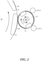
- Fig. 2 is an enlarged view illustrating the vicinity of a region in which a printing plate and a blanket illustrated in Fig. 1 contact one another.
- a printing apparatus 1 illustrated in Fig. 1 is a printing apparatus for offset printing configured to print a can body (printed material) P such as a two-piece can having an approximately cylindrical shape, by transferring ink to the outer circumferential surface (outer surface) of the can body P.
- the printing apparatus 1 includes inking units 10, a blanket wheel 20, a conveyance unit 30, a mandrel wheel 40, a varnish applicator 50, and a transport unit 60.
- the inking units 10 are devices configured to supply ink to printing plates 14.
- the inking unit 10 may be referred to as inker units.
- the inking units 10 are constituted by a plurality of inking units for inks in respectively different colors, that is, constituted by a first inking unit 10a to an eighth inking unit 10h. These inking units 10 are arranged along the outer circumferential surface of the blanket wheel 20.
- Each of the inking units 10 includes an ink supply part 11 configured to store a predetermined ink, and a plate cylinder 13 to which the printing plate 14 corresponding to the ink in the ink supply part 11 is mounted.
- the plurality of ink supply parts 11 are constituted by a first ink supply part 11a to an eighth ink supply part 11h.
- the plurality of printing plates 14 are constituted by a first printing plate 14a to an eighth printing prate 14h to which the inks are supplied from the first ink supply part 11a to the eighth ink supply part 11h, respectively.
- the plate cylinders 13 are constituted by a first plate cylinder 13a to an eighth plate cylinder 13h to which the first printing plate 14a to the eighth printing plate 14h are mounted, respectively.
- the first ink supply part 11a stores the ink in yellow (Y)
- the second ink supply part 11b stores the ink in magenta (M)
- the third ink supply part 11c stores the ink in cyan (C).
- the fourth ink supply part 11d to the eighth ink supply part 11h do not store ink. Therefore, the fourth printing plate 14d to the eighth printing plate 14h respectively corresponding to the fourth ink supply part 11d to the eighth ink supply part 11h are not supplied with ink.
- the ink supply part 11 includes an ink roller group 12 constituted by a fountain roller, a foam roller and so forth.
- the ink supply part 11 supplies the ink stored in an ink repository (not illustrated) to the printing plate 14 mounted to the plate cylinder 13, by rotating the rollers of the ink roller group 12.
- Temperature-controlled water is circulated in part of the rollers of the ink roller group 12 to appropriately keep the temperature of the ink.
- the plate cylinder 13 has an approximately cylindrical shape and can rotate around a spindle, and the printing plate 14 is detachably mounted to the outer circumferential surface of the plate cylinder 13.
- the plate cylinder 13 is provided such that the distance from the blanket wheel 20 can be changed.
- the plate cylinder 13 may be referred to as a printing cylinder.
- the plurality of printing plates 14 (first printing plate 14a to eighth printing plate 14h) are manufactured to overprint the colors extracted by the color separation by the overprint method.
- a plate-making system 100 applies halftone dot forming processing to plate separation image data for each of the colors which is obtained by separating the colors of original image data, and the plurality of printing plates 14 are manufactured, based on the image data for plate-making (plate making image data) which represents halftone dots in each of the colors. Therefore, the plurality of printing plates 14 for the overprinting by the overprint method are manufactured depending on the plate-making image data representing halftone dots in each of colors.
- the plate-making image data of a halftone dot image has a superimposed portion (an overlap portion) in which the image data representing the halftone dots in each of the colors is superimposed onto each other such that at least part of the halftone dots in one color is superimposed onto at least part of the halftone dots in the other colors (to form an overlapping part).
- This printing apparatus 1 can reproduce various colors by the overlap of a plurality of colors, and therefore can realistically print precise designs, for example, as photography, on a can body.
- the ink in yellow (Y) is supplied from the first ink supply part 11a to the first printing plate 14a; the ink in magenta (M) is supplied from the second ink supply part 11b to the second printing plate 14b; and the ink in cyan (C) is supplied from the third ink supply part 11c to the third printing plate 14c.
- the ink in yellow (Y), the ink in magenta (M), and the ink in cyan (C) are put on the first printing plate 14a, the second printing plate 14B, and the third printing plate 14c, respectively, and the colors of the inks put on the printing plates are gradually changed from the color with high lightness (light color: yellow (Y)) on the first printing plate 14a to the color with low lightness (dark color: cyan (C)) on the third printing plate 14c.
- the printing apparatus 1 transfers the inks to the blankets 25 by a so-called wet-on-wet method in which a process to dry the inks is not performed until all the inks have been transferred (laminated) onto the same (one) blanket 25.
- the printing apparatus 1 does not perform the dry process, but transfers (laminates) the inks in the colors onto the same blanket 25 sequentially from the corresponding first printing plate 14a, second printing plate 14b and third printing plate 14c, respectively in this order.
- the inks in different colors are transferred onto the same blanket 25 such that the colors are gradually changed from the color with high lightness (light color: yellow (Y)) on the first printing plate 14a to the color with low lightness (dark color: cyan (C)) on the third printing plate 14c.
- the halftone dots in the dark color with low lightness is superimposed onto at least part of the halftone dots in the light color with high lightness in the same blanket 25.
- the inks in all the colors on this blanket 25 are transferred onto the outer circumferential surface (outer surface) of the can body P at the same time.
- a halftone dot image in which at least part of the halftone dots in one color is superimposed onto at least part of the halftone dots in the other colors is printed on the outer circumferential surface of the can body P.
- the halftone dot image in which at least part of the halftone dots in the light color with high lightness is superimposed onto at least part of the halftone dots in the dark colors with low lightness is printed on the outer circumferential surface of the can body P.
- the can body P is moved from the mandrel 41 to a dryer such as an oven (not illustrated).
- the printing apparatus 1 adopts the wet-on-wet method, and therefore can print a lot of cans at high speed.
- the printing apparatus 1 employs waterless planographic plates as the printing plates 14 (first printing plate 14a to eighth printing plate 14h).
- the waterless planographic plate has image areas on which ink is put, and non-image areas on which ink is not put without water. This printing plate 14 which is a waterless planographic plate will be described in detail later.
- an outlet configured to blow out cold air may be provided in the vicinity of the plate cylinder 13, so that the temperatures of the plate cylinder 13 and the printing plate 14 are appropriately kept.
- the blanket wheel 20 is a device to rotate the blankets 25 configured to rotate to contact the printing plates 14 and the can bodies P to transfer the inks supplied to the printing plates 14 onto the can bodies P.
- the blanket wheel 20 has an approximately cylindrical shape and can rotate around a spindle 22.
- a plurality of segments 21 are provided on the outer circumferential surface of the blanket wheel 20 and arranged at predetermined intervals along the circumferential direction of the blanket wheel 20.
- the blankets 25 are mounted to the outer surfaces of the plurality of segments 21, respectively. In the printing apparatus 1 illustrated in Fig. 1 , twelve blankets 25 are mounted to the segments 21.
- Each of the blankets 25 is an intermediate transfer member configured to mediate the transfer of the ink from the printing plate 14 to the can body P.
- the blanket 25 includes a base material layer made of fabric cloth and foam, and a rubber layer made of acrylonitrile butadiene rubber.
- the base material layer is detachably mounted to the outer surface of the segment 21 via an adhesive material.
- the ink on the printing plate 14 is transferred onto the rubber layer.
- the rubber layer is disposed on the outer surface of the base material layer and constitutes the outer surface of the blanket 25.
- the blanket wheel 20 rotates in the direction of an arrow illustrated in Fig. 1 (counterclockwise), and therefore the ink in yellow (Y) on the first printing plate 14a, the ink in magenta (M) on the second printing plate 14b, and the ink in cyan (C) on the third printing plate 14c are transferred, in this order, onto the same (one) blanket 25.
- the conveyance unit 30 is configured to convey unprinted can bodies P to the mandrel wheel 40. As illustrated in Fig. 1 , the conveyance unit 30 is provided above the mandrel wheel 40. The conveyance unit 30 is provided upstream of the rotating direction of the mandrel wheel 40 from the region in which the can body P held by the mandrel 41 contacts the blanket 25. The conveyance unit 30 conveys the can bodies P one by one from above the mandrel wheel 40 to the upper part of the mandrel wheel 40 by the gravity of the can body P.
- the mandrel wheel 40 is a device configured to rotate the mandrels 41 holding the can bodies P.
- the mandrel wheel 40 is provided next to the blanket wheel 20 in the radial direction of the blanket wheel 20.
- the mandrel wheel 40 has an approximately disc shape and can rotate around the spindle.
- a plurality of mandrels 41 are provided on the outer circumference of the mandrel wheel 40 and arranged at predetermined intervals along the circumferential direction of the mandrel wheel 40.
- Each of the mandrels 41 has an approximately cylindrical shape and can be inserted into the can body P.
- the plurality of mandrels 41 are arranged to protrude in the direction intersecting the mandrel wheel 40, and cantilevered by the outer circumference of the mandrel wheel 40. It is preferred that the number of the mandrels 41 is an integral multiple of the number of the blankets 25. In the printing apparatus 1 illustrated in Fig. 1 , twenty-four mandrels 41 are provided on the mandrel wheel 40.
- the front end of the mandrel 41 absorbs the inner surface of the bottom of the can body P by air suction, and therefore the can body P is held by the mandrel 41.
- the posture of the mandrel 41 can be changed, and the position of the mandrel 41 also can be changed in the radial direction of the mandrel wheel 40.
- the mandrel 41 is provided to be able to rotate around the central axis of the mandrel 41 while holding the can body P.
- the varnish applicator 50 is a device configured to overcoat the can body P to which the ink has been transferred, with finishing varnish.
- the varnish applicator 50 is provided next to the mandrel wheel 40 in the radial direction of the mandrel wheel 40.
- the varnish applicator 50 is provided downstream of the rotating direction of the mandrel wheel 40 from the contact region where the can body P held by the mandrel 41 contacts the blanket 25.
- the transport unit 60 is a device configured to transport the can body P having passed through the varnish applicator 50 from the mandrel 41 to a dryer such as an oven to fix the ink and the overcoat to the can body P.
- the transport unit 60 is provided next to the mandrel wheel 40 in the radial direction of the mandrel wheel 40.
- the transport unit 60 is provided downstream of the rotating direction of the mandrel wheel 40 from the contact region where the can body P held by the mandrel 41 contacts the varnish applicator 50.
- Fig. 3 is a partial cross sectional view illustrating the printing plate 14 which is a waterless planographic plate.
- the printing plate 14 which is a waterless planographic plate includes a base plate 141, a laser heat-sensitive layer 142 and an ink repellent layer 143 which are laminated in this order.
- Image areas 14A on which ink is put are formed by removing the ink repellent layer 143 to expose the laser heat-sensitive layer 142. Meanwhile, non-image areas 14B on which ink is not put are portions on which the ink repellent layer 143 is left.
- the ink repellent layer 143 forming the non-image areas 14B is made of resin such as silicone resin (silicone rubber). By this means, the non-image areas 14B repel ink, so that the ink is not put on the non-image areas 14B.
- the base plate 141 well-known metal plate and film may be used as long as it is a plate material whose dimension is stable.
- the plate material whose dimension is stable is not limited, but any conventional base plates having been used for printing plates may be used.
- the plate material may include paper, paper on which plastic (polyethylene, polypropylene, and polystyrene) is laminated, steel, aluminum (including aluminum alloy), a plate made of metal such as zinc and copper, a film made of plastic such as cellulose acetate, polyethylene terephthalate, polyethylene, polyester, polyamide, polyimide, polystyrene, polypropylene, polycarbonate, and polyvinyl acetal, and paper or a plastic film on which metal is laminated or deposited.
- the laser heat-sensitive layer 142 a laser heat-sensitive layer conventionally applied to a waterless planographic plate may be used.
- the laser heat-sensitive layer 142 may include a composition containing, for example, at least (a)a photothermal conversion material, (b)a metal chelate compound, (c) an active hydrogen-containing compound, and (d) binder resin.
- the laser heat-sensitive layer 142 includes this composition, it is preferred that a cross-link structure is previously formed by the metal chelate compound (b) and the active hydrogen-containing compound (c) before laser irradiation.
- a cross-link structure is previously formed by the metal chelate compound (b) and the active hydrogen-containing compound (c) before laser irradiation.
- the photothermal conversion material (a) is not limited as long as it absorbs the laser beam.
- the laser beam may have a wavelength in any of the ultraviolet region, the visible region, and the infrared region.
- the photothermal conversion material having an absorption region corresponding to the wavelength of the laser beam used may be appropriately selected and used. In particular, carbon black may be preferably used.
- dye which absorbs ultra-violet rays or near infrared rays may be used as the photothermal conversion material.
- the dye having a maximum absorption wavelength of 700 to 900 nm may be preferably used.
- the content of the photothermal conversion material is preferably from 0.1 to 40 % by weight, and more preferably from 0.5 to 25 % by weight based on the total composition of the heat-sensitive layer.
- Examples of the metal chelate compound (b) may include metal diketonate, metal alkoxide, alkyl metal, metal carboxylate salts, a metal oxide chelate compound, a metal complex, and a heterometal chelate compound.
- metal chelate compound particularly preferred may include aluminum, iron (III), titanium acetylacetonate (pentanedionate), ethyl acetoacetonate (hexanedionate), propyl acetoacetonate (heptanedionate), tetramethyl heptanedionate, and benzoyl acetonates. They may be used alone or in combination of two or more.
- the content of the metal chelate compounds in the laser heat-sensitive layer 142 is preferably from 5 to 300 % by weight, more preferably from 10 to 150 % by weight, based on 100 % by weight of the active hydrogen group-containing compound (c).
- Examples of the active hydrogen group-containing compound (c) may include a hydroxyl group-containing compound, an amino group-containing compound, a carboxyl group-containing compound, and a thiol group-containing compound, and, in particular, the hydroxyl group-containing compound is preferably used.
- hydroxyl group-containing compound may include a phenolic hydroxyl group-containing compound, an alcoholic hydroxyl group-containing compound, epoxy acrylate, epoxy methacrylate, polyvinyl butyral resin, and a polymer having a hydroxyl group introduced by a well-known method.
- the content of the active hydrogen group-containing compounds (c) is preferably from 5 to 80 % by weight, more preferably from 20 to 60 % by weight based on the total composition of the laser heat-sensitive layer 142.
- the binder resin (d) is not limited as long as it can be dissolved in organic solvent and has a film forming property.
- Examples of the binder resin (binder polymers) which can be dissolved in organic solvent, and has a film forming property, and further has a function to maintain the morphology may include vinyl polymers, unvulcanized rubber, polyoxides (polyethers), polyesters, polyurethanes, and polyamides. They may be used alone or in combination of two or more.
- the content of the binder polymers is preferably from 5 to 70 % by weight, more preferably from 10 to 50 % by weight, based on the total composition of the laser heat-sensitive layer 142.
- a leveling agent, a surface active agent, a dispersing agent, a plasticizer, a coupling agent and so forth may be optionally added to the laser heat-sensitive layer 142 as needed.
- various coupling agents such as a silane coupling agent, and an unsaturated group-containing compound are added.
- the thickness of the laser heat-sensitive layer 142 is not limited.
- the ink repellent layer 143 is made of, for example, silicone resin (silicone rubber).
- silicone resin silicone rubber
- examples of this silicone rubber may include silicone rubber conventionally used for the waterless planographic plate, and, for example, condensation reaction-type silicon rubber or addition reaction-type silicone rubber is applicable.
- the ink repellent layer 143 is made of addition reaction-type silicone rubber
- the ink repellent layer 143 is formed by applying a silicone rubber composition containing at least a vinyl group-containing organopolysiloxane, a SiH group-containing compound (addition reaction-type cross-linking agent), a reaction inhibitor and a curing catalyst, and drying it as needed.
- the vinyl group-containing organopolysiloxane has a structure represented by the following general formula (A), and has a vinyl group at the end of its main chain or in the main chain.
- the vinyl group-containing organopolysiloxane having a vinyl group at the end of its main chain is preferably used.
- n denotes an integer of 2 or more, and R 1 and R 2 may be the same or different, and each of them denotes a saturated or unsaturated hydrocarbon group having a carbon number of 1 to 50.
- the hydrocarbon group may be linear, branched or cyclic, and may contain an aromatic ring.
- 50 % or more of the entire R 1 and R 2 are methyl groups in view of ink repellency of the printing plate.
- the weight average molecular weight of the vinyl group-containing organopolysiloxane is from 10,000 to 600,000.
- SiH group-containing compound may include an organohydrogen polysiloxane and an organic polymer having a diorganohydrogen silyl group, and in particular, an organohydrogen polysiloxane is preferably used.
- the content of the SiH group-containing compounds is from 0.5 to 20 % by weight, in particular, from 1 to 15 % by weight in the silicone rubber composition.
- reaction inhibitor may include a nitrogen-containing compound, a phosphorus-based compound, an unsaturated alcohol, and in particular, an acetylene group-containing alcohol is preferably used. It is preferred that the content of the reaction inhibitor is from 0.01 to 20 % by weight, in particular, from 0.1 to 15 % by weight in the silicone rubber composition.
- the curing catalyst may be selected from conventionally well-known catalysts, and preferably, may be a platinum-based compound.
- examples of the curing catalyst may include platinum (simple substance), platinum chloride, chloroplatinic acid, olefin-coordinated platinum, an alcohol-modified complex of platinum, and a methyl vinyl polysiloxane complex of platinum.
- the content of the curing catalyst is from 0.001 to 20 % by weight, in particular, from 0.01 to 15 % by weight in the silicone rubber composition.
- a hydroxyl group-containing organopolysiloxane a hydrolyzable functional group-containing silane (or siloxane), silica for the purpose of enhancing the strength of rubber, and a well-known silane coupling agent for the purpose of improving the adhesion may be contained.
- silane coupling agent alkoxysilanes, acetoxysilanes, ketoximino silanes or the like are preferably used, and in particular, those having a vinyl group or an allyl group are preferably used.
- the ink repellent layer 143 is made of condensation reaction-type silicon rubber
- the ink repellent layer 143 is formed by applying a silicone rubber composition containing at least a hydroxyl group-containing organopolysiloxane, a cross-linking agent (deacetation type, deoximation type, dealcoholization type, deamination type, deacetonation type, deamidation type, deaminoxylation type, etc.), and a curing catalyst, and drying it as needed.
- the hydroxyl group-containing organopolysiloxane has the structure represented by the above-described formula (A), which has a hydroxyl group at the end of its main chain or in the main chain.
- the hydroxyl group-containing organopolysiloxane having a hydroxyl group at the end of its main chain is preferably used. It is preferred that 50% or more of the entire R 1 and R 2 in the formula (A) are methyl groups.
- the weight average molecular weight of the hydroxyl group-containing organopolysiloxane is from 10,000 to 600,000.
- acetoxysilanes such as methyl triacetoxysilane, ethyl triacetoxysilane, and vinyl triacetoxysilane
- ketoximino silanes such as vinyl methyl bis(methyl ethyl ketoximino) silane may be preferably used.
- the content of the cross-linking agent is from 0.5 to 20 % by weight, in particular, from 1 to 15 % by weight in the silicone rubber composition.
- the curing catalyst is selected from conventionally well-known curing catalysts, and in particular, dibutyl tin diacetate, dibutyl tin dioctoate, dibutyl tin dilaurate, zinc octoate, iron octoate may be preferably used. It is preferred that the content of the curing catalyst is from 0.001 to 15 % by weight, in particular, from 0.01 to 10 % by weight in the silicon rubber composition.
- the ink repellent layer 143 is not limited, but it is preferred that the thickness is from 2 um to 10pm, in view of the plate durability and the print reproducibility.
- the printing plate 14 which is a waterless planographic plate may include a primer layer between the base plate 141 and the laser heat-sensitive layer 142, in order to improve the adhesion between the base plate 141 and the laser heat-sensitive layer 142, and avoid transferring the heat of the heat-sensitive layer 142 irradiated with the laser beam to the base plate 141.
- the primer layer may contain, for example, epoxy resin, polyurethane resin, phenolic resin, acrylic resin, alkyd resin, polyester resin, polyamide resin, urea resin, and polyvinyl butyral resin.
- epoxy resin polyurethane resin
- phenolic resin acrylic resin
- alkyd resin polyester resin
- polyamide resin polyamide resin
- urea resin polyvinyl butyral resin
- the polyurethane resin, the polyester resin, the acrylic resin, the epoxy resin, and the urea resin are used alone or in combination of two or more.
- the thickness of the primer layer is not limited.
- a cover film to protect the ink repellent layer 143 may be provided. It is preferred that this cover film can allow the laser beam to pass therethrough well.
- the cover film may include a polyester film, a polypropylene film, a polyvinyl alcohol film, a saponified ethylene-vinyl acetate copolymer film, a polyvinylidene chloride film, and a film on which various metals are deposited.
- An original waterless planographic plate as the printing plate 14 may be manufactured by a conventionally well-known method.
- a usual coater such as a reverse roll coater, an air knife coater, a gravure coater, and a die coater, or a spin coating device
- the base plate 141 is coated with a primer layer composition as needed, and heated at 100 to 300 degrees Celsius for several minutes or cured by the irradiation of an active beam.
- the laser heat-sensitive layer composition is applied and heated at 50 to 180 degrees Celsius for several tens of seconds to several minutes, and therefore is cured to form the laser heat-sensitive layer 142.
- the laser heat-sensitive layer 142 is coated with the silicone rubber composition and subjected to heat treatment at 50 to 200 degrees Celsius for several minutes to form the ink repellent layer 143 made of silicone rubber. After that, a cover film is laminated or a protective layer is formed as needed, so that the original waterless planographic plate is manufactured.
- the ink repellent layer 143 (or the cover film) of the original plate is irradiated with the laser beam like streaks from above, and exposed. After that, the irradiated part of the ink repellent layer 143 is removed to form the image areas 14A on which ink I is put. Consequently, the printing plate 14 as a waterless planographic plate is manufactured.
- the printing plate 14 which is a waterless planographic plate with the above-described configuration prevents the ink from being murky, compared to a resin letterpress plate in which the image areas 14A with ink are formed by a resin layer (resin convex portions).
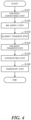
- Fig. 4 is a flowchart illustrating the printing operation of the printing apparatus 1 on the can body P.
- Step S101 Can body conveyance step
- step S101 as a can body conveyance step the printing apparatus 1 conveys the can body P to the upper part of the mandrel wheel 40 by the conveyance unit 30.
- the printing apparatus 1 holds the can body P conveyed to the upper part of the mandrel wheel 40 by the mandrel 41.
- the printing apparatus 1 rotates the mandrel 41 to pre-spin the can body P, and then rotates the mandrel wheel 40 to move the can body P to the contact region where the can body P contacts the blanket 25. That is, the can body P rotates about its axis by the rotation of the mandrel 41, and revolves about the mandrel wheel 40 by the rotation of the mandrel wheel 40.
- Step S102 Ink supply step
- step S102 as an ink supply step following the step S101, the printing apparatus 1 rotates the ink roller group 12 of each of the plurality of ink supply parts 11 to supply the inks stored in the ink supply parts 11 to the printing plates 14 mounted to the plate cylinders 13.
- the printing apparatus 1 supplies the ink in yellow (Y) from the first ink supply part 11a to the first printing plate 14a, supplies the ink in magenta (M) from the second ink supply part 11b to the second printing plate 14b, and supplies the ink in cyan (C) from the third ink supply part 11c to the third printing plate 14c.
- the printing plates 14 to which inks have been supplied are moved to the contact regions where the printing plates 14 contact the blankets 25, respectively.
- Step S103 Blanket transfer step
- step S103 as a blanket transfer step following the step S102, the printing apparatus 1 rotates the blanket wheel 20 to contact the printing plates 14 to which the inks have been supplied, with the blankets 25, so that the inks on the printing plates 14 are transferred to the blankets 25.
- the printing apparatus 1 transfers the inks such that at least part of the ink transferred from one printing plate 14 is superimposed onto at least part of the inks in the other colors transferred from the other printing plates 14.
- the printing apparatus 1 transfers the ink in yellow (Y) on the first printing plate 14a to one blanket 25, transfers the ink in magenta (M) on the second printing plate 14b to the same blanket 25, and then transfers the ink in cyan (C) on the third printing plate 14c to the same blanket 25.
- the image having patterns of the ink repellent layers 143 formed in the printing plates 14 is transferred to the blanket 25.
- Step S104 Can body transfer step
- step S104 as a can body transfer step following the step S103, the printing apparatus 1 rotates the blanket wheel 20 to move the blanket 25 to which the ink has been transferred to the contact region where the can body P contacts the blanket 25. Then, the printing apparatus 1 presses the can body P held by the mandrel 41 to allow contact between the can body P and the blanket 25 having been moved to the contact region, and therefore to transfer the ink on the blanket 25 to the can body P.
- the image having the patterns of the ink repellent layers 143 formed in the printing plates 14 is transferred to the can body P via the blanket 25.
- step S105 as an overcoating step following the step S104, the printing apparatus 1 rotates the mandrel wheel 40 to move the can body P to which the ink has been transferred to the varnish applicator 50, and further to move the can body P to the transport unit 60. Then, the printing apparatus 1 actuates the varnish applicator 50 to overcoat the can body P to which the ink has been transferred.
- Step S106 Transport step
- step S106 as a transport step following the step S105, the printing apparatus 1 actuates the transport unit 60 to transport the can body P having passed through the varnish applicator 50 from the mandrel 41 to a dryer such as an oven (not illustrated).
- a dryer such as an oven
- the printing apparatus 1 rotates the plate cylinders 13, the blanket wheel 20, the mandrels 41 and the mandrel wheel 40 in synchronization with each other.
- the printing apparatus 1 actuates the varnish applicator 50 and the transport unit 60 in synchronization with the rotations of the plate cylinders 13, the blanket wheel 20, the mandrels 41 and the mandrel wheel 40. In this way, the printing apparatus 1 prints the can body P.
- the plate-making system 100 configured to manufacture the printing plates 14 attached to the printing apparatus 1 will be described.
- the plate-making system 100 adopts DTP (Desk Top Publishing) and CTP (Computer To Plate).
- the plate-making system 100 manufactures the printing plates 14 which are waterless planographic plates described above.
- Fig. 5 is a block diagram illustrating the functions of the plate-making system 100 configured to manufacture the printing plates 14 attached to the printing apparatus 1. It is preferred that the plate-making system 100 illustrated in Fig. 5 is a system configured to manufacture the printing plates 14 by DLE (Direct Laser Engraving) method in which resin is sublimated by the heat of the laser and engraved, or LAMS (Laser Ablation Masking System) method in which an image is written to the surface of a resin plate by using the laser and is developed.
- DLE Direct Laser Engraving
- LAMS Laser Ablation Masking System
- the plate-making system 100 includes a data processing device 110 configured to create plate-making image data by applying various image processing to original image data, and a plate manufacturing device 120 configured to manufacture printing plates based on the plate-making image data.
- the data processing device 110 is configured to edit, for example, modify the layout and the color tone of the original plate-making image data described by the page-description language. Then, the data processing device 110 creates the plate-making image data by performing plate separation processing such as the color separation of process colors, and performing halftone dot forming processing to represent the shading of each of the colors by aggregation of halftone dots, and transmits the image data to the plate manufacturing device 120.
- the data processing device 110 includes a processor, a memory, and a program implementing the function of the data processing device 110.
- the data processing device 110 includes a plate separation processing section 111 configured to perform plate separation processing, a halftone dot forming condition setting section 112 configured to set the conditions of the halftone dot forming processing, a halftone dot forming processing section 113 configured to perform the halftone dot forming processing, and a transmission processing section 114 configured to perform transmission processing to transmit data to the plate manufacturing device 120.
- the plate separation processing section 111 separates the colors of the edited original image data into each of the process colors.
- the process colors may be yellow (Y) which is the color of the ink stored in the first ink supply part 11a, magenta (M) which is the color of the ink stored in the second ink supply part 11b, and cyan (C) which is the color of the ink stored in the third ink supply part 11c.
- the plate separation processing section 111 creates plate separation image data which is image data for each of the colors extracted by the color separation of the original image data.
- the halftone dot forming condition setting section 112 sets halftone dot forming conditions to form halftone dots of the plate separation image data created by the plate separation processing section 111.
- the halftone dot forming conditions are set to the plate separation image data for each of the colors.
- the halftone dot forming conditions include the halftone dot shape, the halftone dot area ratio, the number of screen lines (the number of halftone dots lined up per unit area (1 inch)), and the screen angle (the angle at which halftone dots are lined up) for each of the colors, as well as the conditions for the overprint method.
- the conditions for the overprint method may include, for example, the condition for under color removal processing applied to a superimposed portion in which at least part of halftone dots in one color is superimposed onto at least part of halftone dots in the other colors to adjust or remove at least one of the other colors.
- "Halftone dot area ratio" referred herein means the percentage (%) of the halftone dot area per unit area in an image representing halftone dots formed by the halftone dot forming processing (halftone dot image).
- the under color removal processing according to the present embodiment is performed by the halftone dot forming processing section 113, and applied to a superimposed portion in which at least part of halftone dots in one color is superimposed onto at least part of halftone dots in the other colors to adjust or remove at least one of the other colors.
- Adjustment of the color referred herein means to reduce the halftone dot area ratio (%) of at least one of the other colors in the superimposed portion.
- removal of the color referred herein means to completely remove (eliminate) at least one of the other colors in the superimposed portion.
- the halftone dot forming condition setting section 112 sets the condition for the under color removal processing performed by the halftone dot forming processing section 113 as follows. In a case where the halftone dots of the plate separation image data in each color are formed by the overprint method, when, in the superimposed portion in which at least part of halftone dots in one color is superimposed onto at least part of halftone dots in the other colors, the sum of the halftone dot area ratios (%) of the one color and the halftone dot area ratio (%) of the other colors is equal to or smaller than a predetermined reference value (for example, 150 %), the halftone dot forming condition setting section 112 does not set anything to adjust or remove colors.
- a predetermined reference value for example, 150 %
- the halftone dot forming condition setting section 112 sets a changed value of the halftone dot area ratio (%) of at least one of the other colors to adjust or remove the color, so that the sum is equal to or smaller than the predetermined reference value.
- the halftone dot forming condition setting section 112 sets the above-described condition for the under color removal processing.
- the halftone dot forming condition setting section 112 determines that the color to be adjusted or removed at the first priority is the color of the ink transferred first from the printing plates 14 to one blanket 25 (which is yellow (Y) transferred from the first printing plate 14a illustrated in Fig. 1 to the one blanket 25).
- the halftone dot forming condition setting section 112 determines that the color to be adjusted or removed at the second priority is the color of the ink transferred second from the printing plates 14 to the same blanket 25 (which is magenta (M) transferred from the second printing plate 14b illustrated in Fig. 1 to the same blanket 25).
- the halftone dot forming condition setting section 112 sets the priority of the colors to be adjusted or removed such that the colors are determined in the order from yellow (Y) to magenta (M).
- the halftone dot forming condition setting section 112 sets the changed value of the halftone dot area ratio (%) of the color to be adjusted or removed. That is, to "adjust" the under color, the halftone dot area ratio (%) (for example, 50 %) of the under color initially set is changed to a predetermined value (for example, 20 %) greater than 0 %. Meanwhile, to "remove” the under color, the halftone dot area ratio (%) (for example, 50 %) of the under color initially set is changed to 0 %.
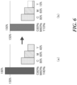
- Fig. 6 illustrates a first example of setting the condition for the under color removal processing.
- image data for a printed image has an overlap portion (image data portion) in which at least part of the halftone dots in magenta (M) is superimposed onto at least part of the halftone dots in yellow (Y), and at least part of the halftone dots in cyan (C) is further superimposed thereon.
- M magenta
- Y yellow
- C cyan
- the halftone dot forming condition setting section 112 sets the reference value (%) of the sum of the halftone dot area ratios to 150 %.
- the sum of the halftone dot area ratios of the three colors, yellow (Y), magenta (M), and cyan (C) is 180 %, and therefore is greater than the reference value of 150 % of the sum of the halftone dot area ratios.
- the halftone dot forming condition setting section 112 sets the condition for the under color removal processing to adjust yellow (Y) transferred first to one blanket 25 so that the sum of the halftone dot area ratios of the three colors, yellow (Y), magenta (M), and cyan (C) is equal to or smaller than the reference value of 150 %.
- the halftone dot forming condition setting section 112 adjusts the halftone dot area ratio of yellow (Y) from the initial value of 40 % to 10 % as illustrated in Fig. 6 (b) (adjustment of yellow (Y)). By this means, the sum of the halftone dot area ratios is equal to the reference value of 150 %.
- Fig. 7 illustrates a second example of setting the condition for the under color removal processing.
- the cyan (C) component having a halftone dot area ratio of 90 %
- the magenta (M) component having a halftone dot area ratio of 60 %
- the yellow (Y) component having a halftone dot area ratio of 40 % overlap each other to form a superimposed portion having the sum of the halftone dot area ratios of 190 %.
- the halftone dot forming condition setting section 112 sets the reference value (%) of the sum of the halftone dot area ratios to 150 %.
- the sum of the halftone dot area ratios of the three colors, yellow (Y), magenta (M), and cyan (C) is 190 %, and therefore is greater than the reference value of 150 % of the sum of the halftone dot area ratios.
- the halftone dot forming condition setting section 112 sets the condition for the under color removal processing to remove yellow (Y) transferred first to one blanket 25 so that the sum of the halftone dot area ratios of the three colors, yellow (Y), magenta (M), and cyan (C) is equal to or smaller than the reference value of 150 %.
- the halftone dot forming condition setting section 112 changes the halftone dot area ratio of yellow (Y) from the initial value of 40 % to 0 % as illustrated in Fig. 7(b) (removal of yellow (Y)). By this means, the sum of the halftone dot area ratios is equal to the reference value of 150 %.
- Fig. 8 illustrates a third example of setting the condition for the under color removal processing.
- the third example for example, as illustrated in Fig. 8(a) , in the image data for a printed image, the cyan (C) component having a halftone dot area ratio of 90 %, the magenta (M) component having a halftone dot area ratio of 70 %, and the yellow (Y) component having a halftone dot area ratio of 40 % overlap each other to form a superimposed portion having the sum of the halftone dot area ratios of 200 %.
- the halftone dot forming condition setting section 112 sets the reference value (%) of the sum of the halftone dot area ratios to 150 %.
- the sum of the halftone dot area ratios of the three colors, yellow (Y), magenta (M), and cyan (C) is 200 %, and therefore is greater than the reference value of 150 % of the sum of the halftone dot area ratios.
- the halftone dot forming condition setting section 112 sets the condition for the under color removal processing to, first, remove yellow (Y) transferred first to one blanket 25 so that the sum of the halftone dot area ratios of the three colors, yellow (Y), magenta (M), and cyan (C) is equal to or smaller than the reference value of 150 %.
- the halftone dot forming condition setting section 112 changes the halftone dot area ratio of yellow (Y) from the initial value of 40 % to 0 % as illustrated in Fig. 8(b) (removal of yellow (Y)). By this means, the sum of the halftone dot area ratios is 160 %, but is still greater than the reference value of 150 %.
- the halftone dot forming condition setting section 112 sets, as the condition for the under color removal processing, to further adjust magenta (M) transferred second to the same blanket 25 as illustrated in Fig. 8(c) .
- the halftone dot forming condition setting section 112 changes the halftone dot area ratio of magenta (M) from the initial value of 70 % to 60 % (adjustment of magenta (M)). By this means, the sum of the halftone dot area ratios is equal to the reference value of 150 %.
- the halftone dot forming processing section 113 forms halftone dots of the plate separation image data in each of the colors created by the plate separation processing section 111, based on the above-described halftone dot forming conditions set by the halftone dot forming condition setting section 112.
- the halftone dot forming processing section 113 forms halftone dots of the plate separation image data in the colors targeted for the overprint method as is on the positive condition (that, for each of the pixels, the higher the density of the color is, the higher the halftone dot area ratio is).
- the image data representing the halftone dots is binary data such as 1 bit TIFF (Tagged Image File Format).
- the image data representing the halftone dots is used as plate-making image data when the plate manufacturing device 120 manufactures a plurality of printing plates 14.
- the halftone dot forming processing section 113 may be configured as a software RIP (Raster Image Processor).
- the halftone dot forming processing section 113 adjusts or removes the under color based on the set condition to form halftone dots of the plate separation image data for each of the colors.
- the transmission processing section 114 performs processing to transmit the image data representing the halftone dots formed by the halftone dot forming processing section 113 to the plate manufacturing device 120 as plate-making image data.
- the plate manufacturing device 120 manufactures the printing plate 14 which is a waterless planographic plate for each of the colors based on the image data transmitted from the transmission processing section 114 of the data processing device 110, that is, the image data representing the halftone dots for each of the colors.
- the plate manufacturing device 120 forms the image areas 14A and the non-image areas 14B by exposing the ink repellent layer 143 (silicone resin layer) to the laser beam based on the image data representing the halftone dots for each of the colors, and peeling and removing the laser-irradiated part of the ink repellent layer 143. In this way, the printing plates 14 which are waterless planographic plates are manufactured.
- the printing plates 14 manufactured by the plate manufacturing device 120 are applicable to the printing apparatus 1.
- Fig. 9 is a flowchart illustrating plate-making operation to manufacture the printing plates 14 by using the plate-making system 100.
- Step S201 to step S206 illustrated in Fig. 9 are performed by the data processing device 110, based on operation commands inputted by a user via a user interface provided in the data processing device 110.
- Step S207 is performed by the plate manufacturing device 120.
- Step S201 Receipt step
- the plate-making system 100 receives original image data by the data processing device 110.
- step S202 as an edit step following the step S201, the plate-making system 100 edits the received original image data.
- the plate-making system 100 corrects the layout to match the printing area of a printed material, and modifies the color tone to edit the original image data.
- Step S203 Plate separation step
- step S203 as a plate separation step following the step S202, the plate-making system 100 applies plate separation processing to the edited original image data.
- the plate-making system 100 separates the colors of the edited original image data into each of the process colors, and creates the plate separation image data for each of the colors.
- Step S203 Halftone dot forming condition setting step
- step S204 as a halftone dot forming condition setting step following the step S203, the plate-making system 100 performs halftone dot forming condition setting processing to set the halftone dot forming conditions for forming halftone dots of the plate separation image data created by the plate separation processing.
- the plate-making system 100 designates the plate separation image data in the colors targeted for the overprint method, and sets the conditions for the overprint method (such as the condition for the under color removal processing as described above), in addition to the halftone dot area ratio, the number of screen lines, and the screen angle per unit area (for example, per pixel) of the designated plate separation image data.
- the plate-making system 100 causes the halftone dot forming condition setting section 112 to determine that the color to be adjusted or removed at the first priority is yellow (Y) transferred first to one blanket 25; and determine that the color to be adjusted or removed at the second priority is magenta (M) transferred second to the same blanket 25, as the condition for the under color removal processing performed by the halftone dot forming processing section 113.
- Y yellow
- M magenta
- the plate-making system 100 causes the halftone dot forming condition setting section 112 to set, for the superimposed portion in which at least part of halftone dots in one color is superimposed onto at least part of halftone dots in the other colors, a changed value of the halftone dot area ratio (%) of one of the other colors to adjust or remove this color, so that the sum of the halftone dot area ratios (%) of the one color and the halftone dot area ratio (%) of the other colors is equal to or smaller than the predetermined reference value.
- the plate-making system 100 causes the halftone dot forming condition setting section 112 to set this condition for the under color removal processing.
- Step S205 Halftone dot forming step
- step S205 as a halftone dot forming step following the step S204, the plate-making system 100 forms halftone dots of the plate separation image data created by the plate separation processing, based on the halftone dot forming conditions set by the halftone dot forming condition setting processing.
- the plate-making system 100 forms the halftone dots of the plate separation image data in the colors targeted for the overprint method as is on the positive condition.
- step S206 as a transmission step following the step S205, the plate-making system 100 performs transmission processing to transmit the image data representing the halftone dots formed by the halftone dot forming processing, as the plate-making image data, from the data processing device 110 to the plate manufacturing device 120.
- Step S207 Plate-making step
- step S207 as a plate-making step following the step S206, the plate-making system 100 manufactures a printing plate for each of the colors by the plate manufacturing device 120, based on the image data transmitted by the transmission processing.
- the plate-making processing illustrated in Fig. 9 ends at this step.
- the process colors are three colors, cyan (C), magenta (M), and yellow (Y).
- the process colors may be seven colors, black (K), red (R), green (G), and blue (B), in addition to those three colors.
- the halftone dot forming condition setting section 112 may set a predetermined screen angle for each of the colors such that the screen angle of halftone dots (the angle at which halftone dots are lined up) varies for each of the colors as a halftone dot forming condition.
- a halftone dot image in which halftone dots in respective colors at screen angles different from each other are superimposed onto each other is printed on the outer circumferential surface (outer surface) of the can body P.
- the halftone dot forming condition setting section 112 may set, as a halftone dot forming condition, the screen angle of the halftone dots in yellow (Y) to 15 degrees, the screen angle of the halftone dots in magenta (M) to 75 degrees, and the screen angle of the halftone dots in cyan (C) to 45 degrees.
- the halftone dot forming condition setting section 112 sets the screen angle of the halftone dots which varies for each of the colors, and therefore it is possible to prevent the inks from being murky and prevent the occurrence of moire even though those colors are overprinted.
- the plurality of printing plates 14 are manufactured based on the plate-making image data representing halftone dots, but this is by no means limiting.
- the plate-making image data of the plurality of printing plates 14 may include the image data of the image portion painted all over by the ink (solid image portion), in addition to the halftone dot image.
- the plurality of printing plates 14 may be manufactured based on the plate-making image data in each of the colors having a superimposed portion in which at least part of the solid image portion in one color (for example, navy (N)) is superimposed onto at least part of the halftone dots in the other colors (for example, at least one of cyan (C), magenta (M), and yellow (Y)).
- the halftone dots in the other colors for example, at least one of cyan (C), magenta (M), and yellow (Y)
- the plurality of printing plates 14 may be manufactured based on the plate-making image data having a superimposed portion in which at least part of a solid image portion in one color is superimposed onto at least part of the halftone dots in the other colors, and at least one of the other colors is adjusted or removed.
- the fourth printing plate 14d may be manufactured based on the image data of the solid image portion.
- the image areas 14A of the fourth printing plate 14d manufactured based on the solid image portion is supplied with the ink in, for example, navy (N).
- at least part of the solid image portion of the plate-making image data of the fourth printing plate 14d may be superimposed onto the other colors, that is, at least part of the halftone dots of the plate-making image data of at least one of the first printing plate 14a (yellow (Y)), the second printing plate 14b (magenta (M)), and the third printing plate 14c (cyan (C)). Then, at least one color of the halftone dots in the other colors may be adjusted or removed in the superimposed portion.
- the halftone dot forming condition setting section 112 may set a condition to adjust or remove the colors sequentially in the order of yellow (Y) for the first printing plate 14a, magenta (M) for the second printing plate 14b, and cyan (C) for the third printing plate 14c according to the priority, based on the sum of the halftone dot area ratios (%) of yellow (Y), cyan (C), magenta (M) and navy (N), and the predetermined reference value, in the same way as the condition for the under color removal processing described above.
- the halftone dot area ratio (%) of navy (N) is 100 % in the solid image portion.
Landscapes
- Engineering & Computer Science (AREA)
- Mechanical Engineering (AREA)
- Printing Methods (AREA)
- Packging For Living Organisms, Food Or Medicinal Products That Are Sensitive To Environmental Conditiond (AREA)
- Printing Plates And Materials Therefor (AREA)
Abstract
Description
- The present invention relates to a printing apparatus, a printing method, and a can body.
- Images with various designs are printed on the outer circumferential surfaces of can bodies used for beverage cans. In many cases, these can bodies are offset printed in order to achieve high-speed production.
- For example, Patent Literature 1 describes a printing technique to perform printing by using printing plates having convex portions for respective colors which do not overlap each other. Each of the inks on the convex portions of the printing plates is transferred to one blanket, and all the colors of the transferred inks are transferred to a can body supported by a rotor at the same time.
- PTL1:
Japanese Patent Application Laid-Open No. H02-262657 - However, with the printing technique using the printing plates as described in Patent Literature 1, designs with solid painting or designs and characters by solid painting can be printed on a can body, but there is a problem that it is difficult to realistically print precise designs, for example, as photography on the can body.
- The present invention has been achieved considering the above-described circumstances to address the above-described problems. It is therefore an aspect of the object of the invention to provide a printing apparatus and a printing method capable of realistically printing precise designs on a can body, and the can body thereby.
- According to the invention, a printing apparatus configured to print a can body includes: a plurality of printing plates; a blanket; a blanket transfer device configured to transfer inks on the plurality of printing plates to the blanket; and a can body transfer device configured to transfer the inks transferred to the blanket to the can body. The blanket transfer device transfers the inks such that at least part of an ink transferred from one printing plate is superimposed onto at least part of inks in other colors transferred from other printing plates.
- It is preferred that a halftone dot image is printed on an outer surface of the can body.
- It is preferred that the blanket transfer device does not allow an ink dry process to be performed until all the inks are transferred to the blanket.
- It is preferred that the plurality of printing plates are manufactured for respective colors depending on an image, the inks corresponding to the colors are put on the plurality of printing plates, respectively, and the inks put on the plurality of printing plates, respectively, are transferred to the blanket.
- It is preferred that the plurality of printing plates are manufactured based on a plate-making image having a superimposed portion in which at least part of halftone dots in one color is superimposed onto at least part of halftone dots in the other colors, and at least one of the other colors is adjusted or removed in the superimposed portion.
- It is preferred that the plurality of printing plates are manufactured based on a plate-making image having a superimposed portion in which at least part of a solid image portion in one color is superimposed onto at least part of halftone dots in the other colors, and at least one of the other colors is adjusted or removed in the superimposed portion.
- It is preferred that the color adjusted or removed in the superimposed portion is a color of an ink transferred first by the blanket transfer device.
- It is preferred that at least one of the other colors is adjusted or removed in the superimposed portion so that a sum of a halftone dot area ratio of the one color and a halftone dot area ratio of the other colors is equal to or smaller than a predetermined reference value.
- It is preferred that the color adjusted or removed in the superimposed portion is determined in an order of yellow (Y), magenta (M), and cyan (C), based on a sum of a halftone dot area ratio of the one color and a halftone dot area ratio of the other colors.
- It is preferred that each of the printing plates is a waterless planographic plate including an image area on which ink is put, and a non-image area on which ink is not put without water.
- According to the invention, a printing method of printing a can body by a plurality of printing plates and a blanket includes: transferring inks on the plurality of printing plates to the blanket; and transferring the inks transferred to the blanket to the can body. The inks are transferred to the blanket such that at least part of an ink transferred from one printing plate is superimposed onto at least part of the inks in other colors transferred from other printing plates.
- According to the invention, a can body printed by a printing apparatus including: a plurality of printing plates; a blanket; a blanket transfer device configured to transfer inks on the plurality of printing plates to the blanket; and a can body transfer device configured to transfer the inks transferred to the blanket to the can body. The blanket transfer device transfers the inks such that at least part of an ink from one printing plate is superimposed onto at least part of the inks in other colors transferred from other printing plates.
- It is preferred that a halftone dot image is printed on an outer surface of the can body, the halftone dot image being formed by superimposing at least part of halftone dots in a color with high lightness onto at least part of halftone dots in a color with low lightness.
- It is preferred that a halftone dot image in which halftone dots in respective colors at screen angles different from each other are superimposed onto each other is printed.
- According to the invention, it is possible to realistically printing precise designs on a can body.
-
-
Fig. 1 schematically illustrates the basic configuration of a printing apparatus according to an embodiment; -
Fig. 2 is an enlarged view illustrating the vicinity of a region in which a printing plate and a blanket illustrated inFig. 1 contact one another; -
Fig. 3 is a partial cross sectional view illustrating a printing plate which is a waterless planographic plate; -
Fig. 4 is a flowchart illustrating the printing operation of the printing apparatus to print a can body; -
Fig. 5 is a block diagram illustrating functions of a plate-making system configured to manufacture printing plates attached to the printing apparatus; -
Fig. 6 illustrates a first example of setting a condition for under color removal processing; -
Fig. 7 illustrates a second example of setting a condition for the under color removal processing; -
Fig. 8 illustrates a third example of setting a condition for the under color removal processing; and -
Fig. 9 is a flowchart illustrating plate-making operation to manufacture printing plates by using the plate-making system. - Hereinafter, an embodiment of the invention (present embodiment) will be described with reference to the drawings.
-
Fig. 1 schematically illustrates the basic configuration of a printing apparatus according to the present embodiment.Fig. 2 is an enlarged view illustrating the vicinity of a region in which a printing plate and a blanket illustrated inFig. 1 contact one another. - A printing apparatus 1 illustrated in
Fig. 1 is a printing apparatus for offset printing configured to print a can body (printed material) P such as a two-piece can having an approximately cylindrical shape, by transferring ink to the outer circumferential surface (outer surface) of the can body P. - As illustrated in
Fig. 1 , the printing apparatus 1 includes inkingunits 10, ablanket wheel 20, aconveyance unit 30, amandrel wheel 40, avarnish applicator 50, and atransport unit 60. - The inking
units 10 are devices configured to supply ink toprinting plates 14. The inkingunit 10 may be referred to as inker units. The inkingunits 10 are constituted by a plurality of inking units for inks in respectively different colors, that is, constituted by afirst inking unit 10a to aneighth inking unit 10h. These inkingunits 10 are arranged along the outer circumferential surface of theblanket wheel 20. Each of theinking units 10 includes anink supply part 11 configured to store a predetermined ink, and aplate cylinder 13 to which theprinting plate 14 corresponding to the ink in theink supply part 11 is mounted. - The plurality of
ink supply parts 11 are constituted by a firstink supply part 11a to an eighthink supply part 11h. The plurality ofprinting plates 14 are constituted by afirst printing plate 14a to an eighth printing prate 14h to which the inks are supplied from the firstink supply part 11a to the eighthink supply part 11h, respectively. Theplate cylinders 13 are constituted by afirst plate cylinder 13a to aneighth plate cylinder 13h to which thefirst printing plate 14a to theeighth printing plate 14h are mounted, respectively. - With the example of the printing apparatus 1 illustrated in
Fig. 1 , the firstink supply part 11a stores the ink in yellow (Y), the secondink supply part 11b stores the ink in magenta (M), and the thirdink supply part 11c stores the ink in cyan (C). - On the other hand, the fourth ink supply
part 11d to the eighthink supply part 11h do not store ink. Therefore, thefourth printing plate 14d to theeighth printing plate 14h respectively corresponding to the fourthink supply part 11d to the eighthink supply part 11h are not supplied with ink. - As illustrated in
Fig. 2 , theink supply part 11 includes anink roller group 12 constituted by a fountain roller, a foam roller and so forth. Theink supply part 11 supplies the ink stored in an ink repository (not illustrated) to theprinting plate 14 mounted to theplate cylinder 13, by rotating the rollers of theink roller group 12. Temperature-controlled water is circulated in part of the rollers of theink roller group 12 to appropriately keep the temperature of the ink. - The
plate cylinder 13 has an approximately cylindrical shape and can rotate around a spindle, and theprinting plate 14 is detachably mounted to the outer circumferential surface of theplate cylinder 13. Theplate cylinder 13 is provided such that the distance from theblanket wheel 20 can be changed. Theplate cylinder 13 may be referred to as a printing cylinder. - To represent colors other than the colors extracted by the color separation, the plurality of printing plates 14 (
first printing plate 14a toeighth printing plate 14h) are manufactured to overprint the colors extracted by the color separation by the overprint method. As described later, a plate-makingsystem 100 applies halftone dot forming processing to plate separation image data for each of the colors which is obtained by separating the colors of original image data, and the plurality ofprinting plates 14 are manufactured, based on the image data for plate-making (plate making image data) which represents halftone dots in each of the colors. Therefore, the plurality ofprinting plates 14 for the overprinting by the overprint method are manufactured depending on the plate-making image data representing halftone dots in each of colors. That is, the plate-making image data of a halftone dot image has a superimposed portion (an overlap portion) in which the image data representing the halftone dots in each of the colors is superimposed onto each other such that at least part of the halftone dots in one color is superimposed onto at least part of the halftone dots in the other colors (to form an overlapping part). - This printing apparatus 1 can reproduce various colors by the overlap of a plurality of colors, and therefore can realistically print precise designs, for example, as photography, on a can body.
- In the printing apparatus 1, the ink in yellow (Y) is supplied from the first
ink supply part 11a to thefirst printing plate 14a; the ink in magenta (M) is supplied from the secondink supply part 11b to the second printing plate 14b; and the ink in cyan (C) is supplied from the thirdink supply part 11c to thethird printing plate 14c. In this way, the ink in yellow (Y), the ink in magenta (M), and the ink in cyan (C) are put on thefirst printing plate 14a, thesecond printing plate 14B, and thethird printing plate 14c, respectively, and the colors of the inks put on the printing plates are gradually changed from the color with high lightness (light color: yellow (Y)) on thefirst printing plate 14a to the color with low lightness (dark color: cyan (C)) on thethird printing plate 14c. - The printing apparatus 1 transfers the inks to the
blankets 25 by a so-called wet-on-wet method in which a process to dry the inks is not performed until all the inks have been transferred (laminated) onto the same (one)blanket 25. With this wet-on-wet method, the printing apparatus 1 does not perform the dry process, but transfers (laminates) the inks in the colors onto thesame blanket 25 sequentially from the correspondingfirst printing plate 14a, second printing plate 14b andthird printing plate 14c, respectively in this order. In this case, the inks in different colors are transferred onto thesame blanket 25 such that the colors are gradually changed from the color with high lightness (light color: yellow (Y)) on thefirst printing plate 14a to the color with low lightness (dark color: cyan (C)) on thethird printing plate 14c. By this means, at least part of the halftone dots in the dark color with low lightness is superimposed onto at least part of the halftone dots in the light color with high lightness in thesame blanket 25. - After all the inks are transferred (laminated) onto the
same blanket 25, the inks in all the colors on thisblanket 25 are transferred onto the outer circumferential surface (outer surface) of the can body P at the same time. By this means, a halftone dot image in which at least part of the halftone dots in one color is superimposed onto at least part of the halftone dots in the other colors is printed on the outer circumferential surface of the can body P. To be more specific, the halftone dot image in which at least part of the halftone dots in the light color with high lightness is superimposed onto at least part of the halftone dots in the dark colors with low lightness is printed on the outer circumferential surface of the can body P. After that, the can body P is moved from themandrel 41 to a dryer such as an oven (not illustrated). The printing apparatus 1 adopts the wet-on-wet method, and therefore can print a lot of cans at high speed. - However, when the wet-on-wet method is adopted for the overprinting by the overprint method as described, the inks may be mixed and murky in the superimposed portion in which the inks in different colors are superimposed onto each other. Therefore, the printing apparatus 1 employs waterless planographic plates as the printing plates 14 (
first printing plate 14a toeighth printing plate 14h). The waterless planographic plate has image areas on which ink is put, and non-image areas on which ink is not put without water. Thisprinting plate 14 which is a waterless planographic plate will be described in detail later. - For example, an outlet configured to blow out cold air may be provided in the vicinity of the
plate cylinder 13, so that the temperatures of theplate cylinder 13 and theprinting plate 14 are appropriately kept. - The
blanket wheel 20 is a device to rotate theblankets 25 configured to rotate to contact theprinting plates 14 and the can bodies P to transfer the inks supplied to theprinting plates 14 onto the can bodies P. As illustrated inFig. 1 , theblanket wheel 20 has an approximately cylindrical shape and can rotate around aspindle 22. As illustrated inFig. 2 , a plurality ofsegments 21 are provided on the outer circumferential surface of theblanket wheel 20 and arranged at predetermined intervals along the circumferential direction of theblanket wheel 20. Theblankets 25 are mounted to the outer surfaces of the plurality ofsegments 21, respectively. In the printing apparatus 1 illustrated inFig. 1 , twelveblankets 25 are mounted to thesegments 21. - Each of the
blankets 25 is an intermediate transfer member configured to mediate the transfer of the ink from theprinting plate 14 to the can body P. Theblanket 25 includes a base material layer made of fabric cloth and foam, and a rubber layer made of acrylonitrile butadiene rubber. The base material layer is detachably mounted to the outer surface of thesegment 21 via an adhesive material. The ink on theprinting plate 14 is transferred onto the rubber layer. The rubber layer is disposed on the outer surface of the base material layer and constitutes the outer surface of theblanket 25. - In the printing apparatus 1, the
blanket wheel 20 rotates in the direction of an arrow illustrated inFig. 1 (counterclockwise), and therefore the ink in yellow (Y) on thefirst printing plate 14a, the ink in magenta (M) on the second printing plate 14b, and the ink in cyan (C) on thethird printing plate 14c are transferred, in this order, onto the same (one)blanket 25. - The
conveyance unit 30 is configured to convey unprinted can bodies P to themandrel wheel 40. As illustrated inFig. 1 , theconveyance unit 30 is provided above themandrel wheel 40. Theconveyance unit 30 is provided upstream of the rotating direction of themandrel wheel 40 from the region in which the can body P held by themandrel 41 contacts theblanket 25. Theconveyance unit 30 conveys the can bodies P one by one from above themandrel wheel 40 to the upper part of themandrel wheel 40 by the gravity of the can body P. - The
mandrel wheel 40 is a device configured to rotate themandrels 41 holding the can bodies P. Themandrel wheel 40 is provided next to theblanket wheel 20 in the radial direction of theblanket wheel 20. Themandrel wheel 40 has an approximately disc shape and can rotate around the spindle. A plurality ofmandrels 41 are provided on the outer circumference of themandrel wheel 40 and arranged at predetermined intervals along the circumferential direction of themandrel wheel 40. - Each of the
mandrels 41 has an approximately cylindrical shape and can be inserted into the can body P. The plurality ofmandrels 41 are arranged to protrude in the direction intersecting themandrel wheel 40, and cantilevered by the outer circumference of themandrel wheel 40. It is preferred that the number of themandrels 41 is an integral multiple of the number of theblankets 25. In the printing apparatus 1 illustrated inFig. 1 , twenty-fourmandrels 41 are provided on themandrel wheel 40. - The front end of the
mandrel 41 absorbs the inner surface of the bottom of the can body P by air suction, and therefore the can body P is held by themandrel 41. The posture of themandrel 41 can be changed, and the position of themandrel 41 also can be changed in the radial direction of themandrel wheel 40. Themandrel 41 is provided to be able to rotate around the central axis of themandrel 41 while holding the can body P. - The
varnish applicator 50 is a device configured to overcoat the can body P to which the ink has been transferred, with finishing varnish. Thevarnish applicator 50 is provided next to themandrel wheel 40 in the radial direction of themandrel wheel 40. Thevarnish applicator 50 is provided downstream of the rotating direction of themandrel wheel 40 from the contact region where the can body P held by themandrel 41 contacts theblanket 25. - The
transport unit 60 is a device configured to transport the can body P having passed through thevarnish applicator 50 from themandrel 41 to a dryer such as an oven to fix the ink and the overcoat to the can body P. Thetransport unit 60 is provided next to themandrel wheel 40 in the radial direction of themandrel wheel 40. Thetransport unit 60 is provided downstream of the rotating direction of themandrel wheel 40 from the contact region where the can body P held by themandrel 41 contacts thevarnish applicator 50. -
Fig. 3 is a partial cross sectional view illustrating theprinting plate 14 which is a waterless planographic plate. As illustrated inFig. 3 , theprinting plate 14 which is a waterless planographic plate includes abase plate 141, a laser heat-sensitive layer 142 and anink repellent layer 143 which are laminated in this order. -
Image areas 14A on which ink is put are formed by removing theink repellent layer 143 to expose the laser heat-sensitive layer 142. Meanwhile,non-image areas 14B on which ink is not put are portions on which theink repellent layer 143 is left. Theink repellent layer 143 forming thenon-image areas 14B is made of resin such as silicone resin (silicone rubber). By this means, thenon-image areas 14B repel ink, so that the ink is not put on thenon-image areas 14B. - As the
base plate 141, well-known metal plate and film may be used as long as it is a plate material whose dimension is stable. The plate material whose dimension is stable is not limited, but any conventional base plates having been used for printing plates may be used. Examples of the plate material may include paper, paper on which plastic (polyethylene, polypropylene, and polystyrene) is laminated, steel, aluminum (including aluminum alloy), a plate made of metal such as zinc and copper, a film made of plastic such as cellulose acetate, polyethylene terephthalate, polyethylene, polyester, polyamide, polyimide, polystyrene, polypropylene, polycarbonate, and polyvinyl acetal, and paper or a plastic film on which metal is laminated or deposited. - As the laser heat-
sensitive layer 142, a laser heat-sensitive layer conventionally applied to a waterless planographic plate may be used. The laser heat-sensitive layer 142 may include a composition containing, for example, at least (a)a photothermal conversion material, (b)a metal chelate compound, (c) an active hydrogen-containing compound, and (d) binder resin. - When the laser heat-
sensitive layer 142 includes this composition, it is preferred that a cross-link structure is previously formed by the metal chelate compound (b) and the active hydrogen-containing compound (c) before laser irradiation. By this means, the adhesion between the heat-sensitive layer and the silicone rubber of the laser-irradiated part deteriorates, and the silicone rubber of the laser-irradiated part is removed by subsequent processing, so that it is possible to obtain a waterless planographic plate. - The photothermal conversion material (a) is not limited as long as it absorbs the laser beam. The laser beam may have a wavelength in any of the ultraviolet region, the visible region, and the infrared region. The photothermal conversion material having an absorption region corresponding to the wavelength of the laser beam used may be appropriately selected and used. In particular, carbon black may be preferably used.
- In addition, dye which absorbs ultra-violet rays or near infrared rays may be used as the photothermal conversion material. The dye having a maximum absorption wavelength of 700 to 900 nm may be preferably used.
- The content of the photothermal conversion material is preferably from 0.1 to 40 % by weight, and more preferably from 0.5 to 25 % by weight based on the total composition of the heat-sensitive layer.
- Examples of the metal chelate compound (b) may include metal diketonate, metal alkoxide, alkyl metal, metal carboxylate salts, a metal oxide chelate compound, a metal complex, and a heterometal chelate compound.
- Examples of the metal chelate compound particularly preferred may include aluminum, iron (III), titanium acetylacetonate (pentanedionate), ethyl acetoacetonate (hexanedionate), propyl acetoacetonate (heptanedionate), tetramethyl heptanedionate, and benzoyl acetonates. They may be used alone or in combination of two or more.
- The content of the metal chelate compounds in the laser heat-
sensitive layer 142 is preferably from 5 to 300 % by weight, more preferably from 10 to 150 % by weight, based on 100 % by weight of the active hydrogen group-containing compound (c). - Examples of the active hydrogen group-containing compound (c) may include a hydroxyl group-containing compound, an amino group-containing compound, a carboxyl group-containing compound, and a thiol group-containing compound, and, in particular, the hydroxyl group-containing compound is preferably used.
- Examples of the hydroxyl group-containing compound may include a phenolic hydroxyl group-containing compound, an alcoholic hydroxyl group-containing compound, epoxy acrylate, epoxy methacrylate, polyvinyl butyral resin, and a polymer having a hydroxyl group introduced by a well-known method.
- The content of the active hydrogen group-containing compounds (c) is preferably from 5 to 80 % by weight, more preferably from 20 to 60 % by weight based on the total composition of the laser heat-
sensitive layer 142. - The binder resin (d) is not limited as long as it can be dissolved in organic solvent and has a film forming property. Examples of the binder resin (binder polymers) which can be dissolved in organic solvent, and has a film forming property, and further has a function to maintain the morphology may include vinyl polymers, unvulcanized rubber, polyoxides (polyethers), polyesters, polyurethanes, and polyamides. They may be used alone or in combination of two or more.
- The content of the binder polymers is preferably from 5 to 70 % by weight, more preferably from 10 to 50 % by weight, based on the total composition of the laser heat-
sensitive layer 142. - A leveling agent, a surface active agent, a dispersing agent, a plasticizer, a coupling agent and so forth may be optionally added to the laser heat-
sensitive layer 142 as needed. In particular, in order to improve the adhesion to the base plate 141 (or primer layer) or theink repellent layer 143, it is preferred that various coupling agents such as a silane coupling agent, and an unsaturated group-containing compound are added. The thickness of the laser heat-sensitive layer 142 is not limited. - It is preferred that the
ink repellent layer 143 is made of, for example, silicone resin (silicone rubber). Examples of this silicone rubber may include silicone rubber conventionally used for the waterless planographic plate, and, for example, condensation reaction-type silicon rubber or addition reaction-type silicone rubber is applicable. - When the
ink repellent layer 143 is made of addition reaction-type silicone rubber, theink repellent layer 143 is formed by applying a silicone rubber composition containing at least a vinyl group-containing organopolysiloxane, a SiH group-containing compound (addition reaction-type cross-linking agent), a reaction inhibitor and a curing catalyst, and drying it as needed. - The vinyl group-containing organopolysiloxane has a structure represented by the following general formula (A), and has a vinyl group at the end of its main chain or in the main chain. In particular, the vinyl group-containing organopolysiloxane having a vinyl group at the end of its main chain is preferably used.
-(SiR1R2-O-)n- (A)
- In the formula (A), n denotes an integer of 2 or more, and R1 and R2 may be the same or different, and each of them denotes a saturated or unsaturated hydrocarbon group having a carbon number of 1 to 50. The hydrocarbon group may be linear, branched or cyclic, and may contain an aromatic ring. In the formula (A), it is preferred that 50 % or more of the entire R1 and R2 are methyl groups in view of ink repellency of the printing plate. In addition, it is preferred that the weight average molecular weight of the vinyl group-containing organopolysiloxane is from 10,000 to 600,000.
- Examples of the SiH group-containing compound may include an organohydrogen polysiloxane and an organic polymer having a diorganohydrogen silyl group, and in particular, an organohydrogen polysiloxane is preferably used.
- It is preferred that the content of the SiH group-containing compounds is from 0.5 to 20 % by weight, in particular, from 1 to 15 % by weight in the silicone rubber composition.
- Examples of the reaction inhibitor may include a nitrogen-containing compound, a phosphorus-based compound, an unsaturated alcohol, and in particular, an acetylene group-containing alcohol is preferably used. It is preferred that the content of the reaction inhibitor is from 0.01 to 20 % by weight, in particular, from 0.1 to 15 % by weight in the silicone rubber composition.
- The curing catalyst may be selected from conventionally well-known catalysts, and preferably, may be a platinum-based compound. To be more specific, examples of the curing catalyst may include platinum (simple substance), platinum chloride, chloroplatinic acid, olefin-coordinated platinum, an alcohol-modified complex of platinum, and a methyl vinyl polysiloxane complex of platinum.
- It is preferred that the content of the curing catalyst is from 0.001 to 20 % by weight, in particular, from 0.01 to 15 % by weight in the silicone rubber composition.
- Moreover, in addition to these components, a hydroxyl group-containing organopolysiloxane, a hydrolyzable functional group-containing silane (or siloxane), silica for the purpose of enhancing the strength of rubber, and a well-known silane coupling agent for the purpose of improving the adhesion may be contained. As the silane coupling agent, alkoxysilanes, acetoxysilanes, ketoximino silanes or the like are preferably used, and in particular, those having a vinyl group or an allyl group are preferably used.
- When the
ink repellent layer 143 is made of condensation reaction-type silicon rubber, theink repellent layer 143 is formed by applying a silicone rubber composition containing at least a hydroxyl group-containing organopolysiloxane, a cross-linking agent (deacetation type, deoximation type, dealcoholization type, deamination type, deacetonation type, deamidation type, deaminoxylation type, etc.), and a curing catalyst, and drying it as needed. - The hydroxyl group-containing organopolysiloxane has the structure represented by the above-described formula (A), which has a hydroxyl group at the end of its main chain or in the main chain. In particular, it is preferred that the hydroxyl group-containing organopolysiloxane having a hydroxyl group at the end of its main chain is preferably used. It is preferred that 50% or more of the entire R1 and R2 in the formula (A) are methyl groups. In addition, it is preferred that the weight average molecular weight of the hydroxyl group-containing organopolysiloxane is from 10,000 to 600,000.
- As a cross-linking agent used for the condensation reaction-type silicone rubber layer, for example, acetoxysilanes such as methyl triacetoxysilane, ethyl triacetoxysilane, and vinyl triacetoxysilane, and ketoximino silanes such as vinyl methyl bis(methyl ethyl ketoximino) silane may be preferably used.
- It is preferred that the content of the cross-linking agent is from 0.5 to 20 % by weight, in particular, from 1 to 15 % by weight in the silicone rubber composition.
- The curing catalyst is selected from conventionally well-known curing catalysts, and in particular, dibutyl tin diacetate, dibutyl tin dioctoate, dibutyl tin dilaurate, zinc octoate, iron octoate may be preferably used. It is preferred that the content of the curing catalyst is from 0.001 to 15 % by weight, in particular, from 0.01 to 10 % by weight in the silicon rubber composition.
- Moreover, in addition to these components, for the purpose of enhancing the strength of rubber, a well-known filler such as silica, and a well-known silane coupling agent may be contained. The thickness of the
ink repellent layer 143 is not limited, but it is preferred that the thickness is from 2 um to 10pm, in view of the plate durability and the print reproducibility. - The
printing plate 14 which is a waterless planographic plate may include a primer layer between thebase plate 141 and the laser heat-sensitive layer 142, in order to improve the adhesion between thebase plate 141 and the laser heat-sensitive layer 142, and avoid transferring the heat of the heat-sensitive layer 142 irradiated with the laser beam to thebase plate 141. - The primer layer may contain, for example, epoxy resin, polyurethane resin, phenolic resin, acrylic resin, alkyd resin, polyester resin, polyamide resin, urea resin, and polyvinyl butyral resin. In particular, for example, it is preferred that the polyurethane resin, the polyester resin, the acrylic resin, the epoxy resin, and the urea resin are used alone or in combination of two or more. In addition, the thickness of the primer layer is not limited.
- Moreover, a cover film to protect the
ink repellent layer 143 may be provided. It is preferred that this cover film can allow the laser beam to pass therethrough well. Examples of the cover film may include a polyester film, a polypropylene film, a polyvinyl alcohol film, a saponified ethylene-vinyl acetate copolymer film, a polyvinylidene chloride film, and a film on which various metals are deposited. - An original waterless planographic plate as the
printing plate 14 may be manufactured by a conventionally well-known method. For example, by using a usual coater such as a reverse roll coater, an air knife coater, a gravure coater, and a die coater, or a spin coating device, thebase plate 141 is coated with a primer layer composition as needed, and heated at 100 to 300 degrees Celsius for several minutes or cured by the irradiation of an active beam. After that, the laser heat-sensitive layer composition is applied and heated at 50 to 180 degrees Celsius for several tens of seconds to several minutes, and therefore is cured to form the laser heat-sensitive layer 142. Next, the laser heat-sensitive layer 142 is coated with the silicone rubber composition and subjected to heat treatment at 50 to 200 degrees Celsius for several minutes to form theink repellent layer 143 made of silicone rubber. After that, a cover film is laminated or a protective layer is formed as needed, so that the original waterless planographic plate is manufactured. - The ink repellent layer 143 (or the cover film) of the original plate is irradiated with the laser beam like streaks from above, and exposed. After that, the irradiated part of the
ink repellent layer 143 is removed to form theimage areas 14A on which ink I is put. Consequently, theprinting plate 14 as a waterless planographic plate is manufactured. - The
printing plate 14 which is a waterless planographic plate with the above-described configuration prevents the ink from being murky, compared to a resin letterpress plate in which theimage areas 14A with ink are formed by a resin layer (resin convex portions). -
Fig. 4 is a flowchart illustrating the printing operation of the printing apparatus 1 on the can body P. - In step S101 as a can body conveyance step, the printing apparatus 1 conveys the can body P to the upper part of the
mandrel wheel 40 by theconveyance unit 30. The printing apparatus 1 holds the can body P conveyed to the upper part of themandrel wheel 40 by themandrel 41. Before the can body P contacts theblanket 25, the printing apparatus 1 rotates themandrel 41 to pre-spin the can body P, and then rotates themandrel wheel 40 to move the can body P to the contact region where the can body P contacts theblanket 25. That is, the can body P rotates about its axis by the rotation of themandrel 41, and revolves about themandrel wheel 40 by the rotation of themandrel wheel 40. - In step S102 as an ink supply step following the step S101, the printing apparatus 1 rotates the
ink roller group 12 of each of the plurality ofink supply parts 11 to supply the inks stored in theink supply parts 11 to theprinting plates 14 mounted to theplate cylinders 13. - In this step S102, the printing apparatus 1 supplies the ink in yellow (Y) from the first
ink supply part 11a to thefirst printing plate 14a, supplies the ink in magenta (M) from the secondink supply part 11b to the second printing plate 14b, and supplies the ink in cyan (C) from the thirdink supply part 11c to thethird printing plate 14c. - By the rotation of the
plate cylinders 13, theprinting plates 14 to which inks have been supplied are moved to the contact regions where theprinting plates 14 contact theblankets 25, respectively. - In step S103 as a blanket transfer step following the step S102, the printing apparatus 1 rotates the
blanket wheel 20 to contact theprinting plates 14 to which the inks have been supplied, with theblankets 25, so that the inks on theprinting plates 14 are transferred to theblankets 25. In this step S103, the printing apparatus 1 transfers the inks such that at least part of the ink transferred from oneprinting plate 14 is superimposed onto at least part of the inks in the other colors transferred from theother printing plates 14. - In the step S103, the printing apparatus 1 transfers the ink in yellow (Y) on the
first printing plate 14a to oneblanket 25, transfers the ink in magenta (M) on the second printing plate 14b to thesame blanket 25, and then transfers the ink in cyan (C) on thethird printing plate 14c to thesame blanket 25. - By this means, the image having patterns of the ink repellent layers 143 formed in the
printing plates 14 is transferred to theblanket 25. - In step S104 as a can body transfer step following the step S103, the printing apparatus 1 rotates the
blanket wheel 20 to move theblanket 25 to which the ink has been transferred to the contact region where the can body P contacts theblanket 25. Then, the printing apparatus 1 presses the can body P held by themandrel 41 to allow contact between the can body P and theblanket 25 having been moved to the contact region, and therefore to transfer the ink on theblanket 25 to the can body P. By this means, the image having the patterns of the ink repellent layers 143 formed in theprinting plates 14 is transferred to the can body P via theblanket 25. - In step S105 as an overcoating step following the step S104, the printing apparatus 1 rotates the
mandrel wheel 40 to move the can body P to which the ink has been transferred to thevarnish applicator 50, and further to move the can body P to thetransport unit 60. Then, the printing apparatus 1 actuates thevarnish applicator 50 to overcoat the can body P to which the ink has been transferred. - In step S106 as a transport step following the step S105, the printing apparatus 1 actuates the
transport unit 60 to transport the can body P having passed through thevarnish applicator 50 from themandrel 41 to a dryer such as an oven (not illustrated). - Here, the printing apparatus 1 rotates the
plate cylinders 13, theblanket wheel 20, themandrels 41 and themandrel wheel 40 in synchronization with each other. In addition, the printing apparatus 1 actuates thevarnish applicator 50 and thetransport unit 60 in synchronization with the rotations of theplate cylinders 13, theblanket wheel 20, themandrels 41 and themandrel wheel 40. In this way, the printing apparatus 1 prints the can body P. - Next, a plate-making
system 100 configured to manufacture theprinting plates 14 attached to the printing apparatus 1 will be described. The plate-makingsystem 100 adopts DTP (Desk Top Publishing) and CTP (Computer To Plate). The plate-makingsystem 100 manufactures theprinting plates 14 which are waterless planographic plates described above. -
Fig. 5 is a block diagram illustrating the functions of the plate-makingsystem 100 configured to manufacture theprinting plates 14 attached to the printing apparatus 1. It is preferred that the plate-makingsystem 100 illustrated inFig. 5 is a system configured to manufacture theprinting plates 14 by DLE (Direct Laser Engraving) method in which resin is sublimated by the heat of the laser and engraved, or LAMS (Laser Ablation Masking System) method in which an image is written to the surface of a resin plate by using the laser and is developed. - The plate-making
system 100 includes adata processing device 110 configured to create plate-making image data by applying various image processing to original image data, and aplate manufacturing device 120 configured to manufacture printing plates based on the plate-making image data. - The
data processing device 110 is configured to edit, for example, modify the layout and the color tone of the original plate-making image data described by the page-description language. Then, thedata processing device 110 creates the plate-making image data by performing plate separation processing such as the color separation of process colors, and performing halftone dot forming processing to represent the shading of each of the colors by aggregation of halftone dots, and transmits the image data to theplate manufacturing device 120. Thedata processing device 110 includes a processor, a memory, and a program implementing the function of thedata processing device 110. - The
data processing device 110 includes a plateseparation processing section 111 configured to perform plate separation processing, a halftone dot formingcondition setting section 112 configured to set the conditions of the halftone dot forming processing, a halftone dot formingprocessing section 113 configured to perform the halftone dot forming processing, and atransmission processing section 114 configured to perform transmission processing to transmit data to theplate manufacturing device 120. - The plate
separation processing section 111 separates the colors of the edited original image data into each of the process colors. The process colors may be yellow (Y) which is the color of the ink stored in the firstink supply part 11a, magenta (M) which is the color of the ink stored in the secondink supply part 11b, and cyan (C) which is the color of the ink stored in the thirdink supply part 11c. The plateseparation processing section 111 creates plate separation image data which is image data for each of the colors extracted by the color separation of the original image data. - The halftone dot forming
condition setting section 112 sets halftone dot forming conditions to form halftone dots of the plate separation image data created by the plateseparation processing section 111. The halftone dot forming conditions are set to the plate separation image data for each of the colors. The halftone dot forming conditions include the halftone dot shape, the halftone dot area ratio, the number of screen lines (the number of halftone dots lined up per unit area (1 inch)), and the screen angle (the angle at which halftone dots are lined up) for each of the colors, as well as the conditions for the overprint method. The conditions for the overprint method may include, for example, the condition for under color removal processing applied to a superimposed portion in which at least part of halftone dots in one color is superimposed onto at least part of halftone dots in the other colors to adjust or remove at least one of the other colors. "Halftone dot area ratio" referred herein means the percentage (%) of the halftone dot area per unit area in an image representing halftone dots formed by the halftone dot forming processing (halftone dot image). - The under color removal processing according to the present embodiment is performed by the halftone dot forming
processing section 113, and applied to a superimposed portion in which at least part of halftone dots in one color is superimposed onto at least part of halftone dots in the other colors to adjust or remove at least one of the other colors. "Adjustment" of the color referred herein means to reduce the halftone dot area ratio (%) of at least one of the other colors in the superimposed portion. In addition, "removal" of the color referred herein means to completely remove (eliminate) at least one of the other colors in the superimposed portion. - The halftone dot forming
condition setting section 112 sets the condition for the under color removal processing performed by the halftone dot formingprocessing section 113 as follows. In a case where the halftone dots of the plate separation image data in each color are formed by the overprint method, when, in the superimposed portion in which at least part of halftone dots in one color is superimposed onto at least part of halftone dots in the other colors, the sum of the halftone dot area ratios (%) of the one color and the halftone dot area ratio (%) of the other colors is equal to or smaller than a predetermined reference value (for example, 150 %), the halftone dot formingcondition setting section 112 does not set anything to adjust or remove colors. On the other hand, when the sum is greater than the predetermined reference value (for example, 150 %), the halftone dot formingcondition setting section 112 sets a changed value of the halftone dot area ratio (%) of at least one of the other colors to adjust or remove the color, so that the sum is equal to or smaller than the predetermined reference value. The halftone dot formingcondition setting section 112 sets the above-described condition for the under color removal processing. - Here, as the condition for the under color removal processing, the halftone dot forming
condition setting section 112 determines that the color to be adjusted or removed at the first priority is the color of the ink transferred first from theprinting plates 14 to one blanket 25 (which is yellow (Y) transferred from thefirst printing plate 14a illustrated inFig. 1 to the one blanket 25). In addition, the halftone dot formingcondition setting section 112 determines that the color to be adjusted or removed at the second priority is the color of the ink transferred second from theprinting plates 14 to the same blanket 25 (which is magenta (M) transferred from the second printing plate 14b illustrated inFig. 1 to the same blanket 25). - In this way, as the condition for the under color removal processing, the halftone dot forming
condition setting section 112 sets the priority of the colors to be adjusted or removed such that the colors are determined in the order from yellow (Y) to magenta (M). - Moreover, as the condition for the under color removal processing, the halftone dot forming
condition setting section 112 sets the changed value of the halftone dot area ratio (%) of the color to be adjusted or removed. That is, to "adjust" the under color, the halftone dot area ratio (%) (for example, 50 %) of the under color initially set is changed to a predetermined value (for example, 20 %) greater than 0 %. Meanwhile, to "remove" the under color, the halftone dot area ratio (%) (for example, 50 %) of the under color initially set is changed to 0 %. - Hereinafter, specific examples of setting the condition for the under color removal processing will be described with reference to
Fig. 6 to 8 .Fig. 6 illustrates a first example of setting the condition for the under color removal processing. With the overprint method, image data for a printed image has an overlap portion (image data portion) in which at least part of the halftone dots in magenta (M) is superimposed onto at least part of the halftone dots in yellow (Y), and at least part of the halftone dots in cyan (C) is further superimposed thereon. - With the first example, for example, as illustrated in
Fig. 6(a) , in the image data for a printed image, the cyan (C) component having a halftone dot area ratio of 80 %, the magenta (M) component having a halftone dot area ratio of 60 %, and the yellow (Y) component having a halftone dot area ratio of 40 % overlap each other to form a superimposed portion having the sum of the halftone dot area ratios of 180 %. With the first example, the halftone dot formingcondition setting section 112 sets the reference value (%) of the sum of the halftone dot area ratios to 150 %. - With the first example, the sum of the halftone dot area ratios of the three colors, yellow (Y), magenta (M), and cyan (C) is 180 %, and therefore is greater than the reference value of 150 % of the sum of the halftone dot area ratios.
- To address this, with the first example, the halftone dot forming
condition setting section 112 sets the condition for the under color removal processing to adjust yellow (Y) transferred first to oneblanket 25 so that the sum of the halftone dot area ratios of the three colors, yellow (Y), magenta (M), and cyan (C) is equal to or smaller than the reference value of 150 %. To be more specific, the halftone dot formingcondition setting section 112 adjusts the halftone dot area ratio of yellow (Y) from the initial value of 40 % to 10 % as illustrated inFig. 6 (b) (adjustment of yellow (Y)). By this means, the sum of the halftone dot area ratios is equal to the reference value of 150 %. -
Fig. 7 illustrates a second example of setting the condition for the under color removal processing. With the second example, for example, as illustrated inFig. 7(a) , in the image data for a printed image, the cyan (C) component having a halftone dot area ratio of 90 %, the magenta (M) component having a halftone dot area ratio of 60 %, and the yellow (Y) component having a halftone dot area ratio of 40 % overlap each other to form a superimposed portion having the sum of the halftone dot area ratios of 190 %. Also with the second example, the halftone dot formingcondition setting section 112 sets the reference value (%) of the sum of the halftone dot area ratios to 150 %. - With the second example, the sum of the halftone dot area ratios of the three colors, yellow (Y), magenta (M), and cyan (C) is 190 %, and therefore is greater than the reference value of 150 % of the sum of the halftone dot area ratios.
- To address this, with the second example, the halftone dot forming
condition setting section 112 sets the condition for the under color removal processing to remove yellow (Y) transferred first to oneblanket 25 so that the sum of the halftone dot area ratios of the three colors, yellow (Y), magenta (M), and cyan (C) is equal to or smaller than the reference value of 150 %. To be more specific, the halftone dot formingcondition setting section 112 changes the halftone dot area ratio of yellow (Y) from the initial value of 40 % to 0 % as illustrated inFig. 7(b) (removal of yellow (Y)). By this means, the sum of the halftone dot area ratios is equal to the reference value of 150 %. -
Fig. 8 illustrates a third example of setting the condition for the under color removal processing. With the third example, for example, as illustrated inFig. 8(a) , in the image data for a printed image, the cyan (C) component having a halftone dot area ratio of 90 %, the magenta (M) component having a halftone dot area ratio of 70 %, and the yellow (Y) component having a halftone dot area ratio of 40 % overlap each other to form a superimposed portion having the sum of the halftone dot area ratios of 200 %. Also with the third example, the halftone dot formingcondition setting section 112 sets the reference value (%) of the sum of the halftone dot area ratios to 150 %. - With the third example, the sum of the halftone dot area ratios of the three colors, yellow (Y), magenta (M), and cyan (C) is 200 %, and therefore is greater than the reference value of 150 % of the sum of the halftone dot area ratios.
- To address this, with the third example, the halftone dot forming
condition setting section 112 sets the condition for the under color removal processing to, first, remove yellow (Y) transferred first to oneblanket 25 so that the sum of the halftone dot area ratios of the three colors, yellow (Y), magenta (M), and cyan (C) is equal to or smaller than the reference value of 150 %. To be more specific, the halftone dot formingcondition setting section 112 changes the halftone dot area ratio of yellow (Y) from the initial value of 40 % to 0 % as illustrated inFig. 8(b) (removal of yellow (Y)). By this means, the sum of the halftone dot area ratios is 160 %, but is still greater than the reference value of 150 %. - Therefore, with the third example, the halftone dot forming
condition setting section 112 sets, as the condition for the under color removal processing, to further adjust magenta (M) transferred second to thesame blanket 25 as illustrated inFig. 8(c) . To be more specific, as illustrated inFig. 8(c) , the halftone dot formingcondition setting section 112 changes the halftone dot area ratio of magenta (M) from the initial value of 70 % to 60 % (adjustment of magenta (M)). By this means, the sum of the halftone dot area ratios is equal to the reference value of 150 %. - The halftone dot forming
processing section 113 forms halftone dots of the plate separation image data in each of the colors created by the plateseparation processing section 111, based on the above-described halftone dot forming conditions set by the halftone dot formingcondition setting section 112. The halftone dot formingprocessing section 113 forms halftone dots of the plate separation image data in the colors targeted for the overprint method as is on the positive condition (that, for each of the pixels, the higher the density of the color is, the higher the halftone dot area ratio is). The image data representing the halftone dots is binary data such as 1 bit TIFF (Tagged Image File Format). The image data representing the halftone dots is used as plate-making image data when theplate manufacturing device 120 manufactures a plurality ofprinting plates 14. The halftone dot formingprocessing section 113 may be configured as a software RIP (Raster Image Processor). - In the case where the halftone dot forming
condition setting section 112 sets the condition for the under color removal processing as described above, the halftone dot formingprocessing section 113 adjusts or removes the under color based on the set condition to form halftone dots of the plate separation image data for each of the colors. - The
transmission processing section 114 performs processing to transmit the image data representing the halftone dots formed by the halftone dot formingprocessing section 113 to theplate manufacturing device 120 as plate-making image data. - The
plate manufacturing device 120 manufactures theprinting plate 14 which is a waterless planographic plate for each of the colors based on the image data transmitted from thetransmission processing section 114 of thedata processing device 110, that is, the image data representing the halftone dots for each of the colors. Theplate manufacturing device 120 forms theimage areas 14A and thenon-image areas 14B by exposing the ink repellent layer 143 (silicone resin layer) to the laser beam based on the image data representing the halftone dots for each of the colors, and peeling and removing the laser-irradiated part of theink repellent layer 143. In this way, theprinting plates 14 which are waterless planographic plates are manufactured. Theprinting plates 14 manufactured by theplate manufacturing device 120 are applicable to the printing apparatus 1. -
Fig. 9 is a flowchart illustrating plate-making operation to manufacture theprinting plates 14 by using the plate-makingsystem 100. - Step S201 to step S206 illustrated in
Fig. 9 are performed by thedata processing device 110, based on operation commands inputted by a user via a user interface provided in thedata processing device 110. Step S207 is performed by theplate manufacturing device 120. - In the step S201 as a receipt step, the plate-making
system 100 receives original image data by thedata processing device 110. - In step S202 as an edit step following the step S201, the plate-making
system 100 edits the received original image data. The plate-makingsystem 100 corrects the layout to match the printing area of a printed material, and modifies the color tone to edit the original image data. - In step S203 as a plate separation step following the step S202, the plate-making
system 100 applies plate separation processing to the edited original image data. The plate-makingsystem 100 separates the colors of the edited original image data into each of the process colors, and creates the plate separation image data for each of the colors. - In step S204 as a halftone dot forming condition setting step following the step S203, the plate-making
system 100 performs halftone dot forming condition setting processing to set the halftone dot forming conditions for forming halftone dots of the plate separation image data created by the plate separation processing. In particular, the plate-makingsystem 100 designates the plate separation image data in the colors targeted for the overprint method, and sets the conditions for the overprint method (such as the condition for the under color removal processing as described above), in addition to the halftone dot area ratio, the number of screen lines, and the screen angle per unit area (for example, per pixel) of the designated plate separation image data. - In this step S204, the plate-making
system 100 causes the halftone dot formingcondition setting section 112 to determine that the color to be adjusted or removed at the first priority is yellow (Y) transferred first to oneblanket 25; and determine that the color to be adjusted or removed at the second priority is magenta (M) transferred second to thesame blanket 25, as the condition for the under color removal processing performed by the halftone dot formingprocessing section 113. - Then, in the step S204, to form halftone dots of the plate separation image data for each of the colors by the overprint method, the plate-making
system 100 causes the halftone dot formingcondition setting section 112 to set, for the superimposed portion in which at least part of halftone dots in one color is superimposed onto at least part of halftone dots in the other colors, a changed value of the halftone dot area ratio (%) of one of the other colors to adjust or remove this color, so that the sum of the halftone dot area ratios (%) of the one color and the halftone dot area ratio (%) of the other colors is equal to or smaller than the predetermined reference value. The plate-makingsystem 100 causes the halftone dot formingcondition setting section 112 to set this condition for the under color removal processing. - In step S205 as a halftone dot forming step following the step S204, the plate-making
system 100 forms halftone dots of the plate separation image data created by the plate separation processing, based on the halftone dot forming conditions set by the halftone dot forming condition setting processing. Here, the plate-makingsystem 100 forms the halftone dots of the plate separation image data in the colors targeted for the overprint method as is on the positive condition. - In step S206 as a transmission step following the step S205, the plate-making
system 100 performs transmission processing to transmit the image data representing the halftone dots formed by the halftone dot forming processing, as the plate-making image data, from thedata processing device 110 to theplate manufacturing device 120. - In step S207 as a plate-making step following the step S206, the plate-making
system 100 manufactures a printing plate for each of the colors by theplate manufacturing device 120, based on the image data transmitted by the transmission processing. The plate-making processing illustrated inFig. 9 ends at this step. - The above-described embodiments including a modification may apply their features to each other. The above-described embodiments are not intended to limit the subject matter of the invention but may be modified to the extent not to depart from the scope of the claims.
- For example, with the above-described embodiment, the process colors are three colors, cyan (C), magenta (M), and yellow (Y). However, the process colors may be seven colors, black (K), red (R), green (G), and blue (B), in addition to those three colors.
- In addition, for example, with the above-described embodiment, the halftone dot forming
condition setting section 112 may set a predetermined screen angle for each of the colors such that the screen angle of halftone dots (the angle at which halftone dots are lined up) varies for each of the colors as a halftone dot forming condition. By this means, a halftone dot image in which halftone dots in respective colors at screen angles different from each other are superimposed onto each other is printed on the outer circumferential surface (outer surface) of the can body P. - For example, the halftone dot forming
condition setting section 112 may set, as a halftone dot forming condition, the screen angle of the halftone dots in yellow (Y) to 15 degrees, the screen angle of the halftone dots in magenta (M) to 75 degrees, and the screen angle of the halftone dots in cyan (C) to 45 degrees. In this way, the halftone dot formingcondition setting section 112 sets the screen angle of the halftone dots which varies for each of the colors, and therefore it is possible to prevent the inks from being murky and prevent the occurrence of moire even though those colors are overprinted. - Moreover, with the above-described embodiment, the plurality of
printing plates 14 are manufactured based on the plate-making image data representing halftone dots, but this is by no means limiting. For example, the plate-making image data of the plurality ofprinting plates 14 may include the image data of the image portion painted all over by the ink (solid image portion), in addition to the halftone dot image. - In this case, the plurality of
printing plates 14 may be manufactured based on the plate-making image data in each of the colors having a superimposed portion in which at least part of the solid image portion in one color (for example, navy (N)) is superimposed onto at least part of the halftone dots in the other colors (for example, at least one of cyan (C), magenta (M), and yellow (Y)). By this means, it is possible to print an image having a superimposed portion in which at least part of the halftone dots in the other colors (for example, at least one of cyan (C), magenta (M), and yellow (Y)) is superimposed onto at least part of the one color (for example, navy (N)). - In this case, the plurality of
printing plates 14 may be manufactured based on the plate-making image data having a superimposed portion in which at least part of a solid image portion in one color is superimposed onto at least part of the halftone dots in the other colors, and at least one of the other colors is adjusted or removed. - For example, with the example illustrated in
Fig. 1 , thefourth printing plate 14d may be manufactured based on the image data of the solid image portion. In this case, theimage areas 14A of thefourth printing plate 14d manufactured based on the solid image portion is supplied with the ink in, for example, navy (N). Here, at least part of the solid image portion of the plate-making image data of thefourth printing plate 14d may be superimposed onto the other colors, that is, at least part of the halftone dots of the plate-making image data of at least one of thefirst printing plate 14a (yellow (Y)), the second printing plate 14b (magenta (M)), and thethird printing plate 14c (cyan (C)). Then, at least one color of the halftone dots in the other colors may be adjusted or removed in the superimposed portion. - In this case, the halftone dot forming
condition setting section 112 may set a condition to adjust or remove the colors sequentially in the order of yellow (Y) for thefirst printing plate 14a, magenta (M) for the second printing plate 14b, and cyan (C) for thethird printing plate 14c according to the priority, based on the sum of the halftone dot area ratios (%) of yellow (Y), cyan (C), magenta (M) and navy (N), and the predetermined reference value, in the same way as the condition for the under color removal processing described above. Here, the halftone dot area ratio (%) of navy (N) is 100 % in the solid image portion. -
- 1 printing apparatus, 10 inking unit,
- 10a to 10h first inking unit to eighth inking unit,
- 11 ink supply part,
- 11a to 11h first ink supply part to eighth ink supply part,
- 12 ink roller group, 13 plate cylinder,
- 13a to 13h first ink cylinder to eighth ink cylinder,
- 14 printing plate,
- 14a to 14h first printing plate to eighth printing plate,
- 20 blanket wheel, 21 segment, 22 spindle,
- 25 blanket, 30 conveyance unit, 40 mandrel wheel,
- 41 mandrel, 50 varnish applicator,
- 60 transport unit, 100 plate-making system,
- 110 data processing device,
- 111 plate separation processing section,
- 112 halftone dot forming condition setting section,
- 113 halftone dot forming processing section,
- 114 transmission processing section,
- 120 plate manufacturing device,
- 141 base plate, 142 laser heat-sensitive layer,
- 143 ink repellent layer
Claims (14)
- A printing apparatus configured to print a can body, comprising:a plurality of printing plates;a blanket;a blanket transfer device configured to transfer inks on the plurality of printing plates to the blanket; anda can body transfer device configured to transfer the inks transferred to the blanket to the can body,wherein the blanket transfer device transfers the inks such that at least part of an ink transferred from one printing plate is superimposed onto at least part of inks in other colors transferred from other printing plates.
- The printing apparatus according to claim 1, wherein a halftone dot image is printed on an outer surface of the can body.
- The printing apparatus according to one of claims 1 and 2, wherein the blanket transfer device does not allow an ink dry process to be performed until all the inks are transferred to the blanket.
- The printing apparatus according to one of claims 1 to 3, wherein:the plurality of printing plates are manufactured for respective colors depending on an image;the inks corresponding to the colors are put on the plurality of printing plates, respectively; andthe inks put on the plurality of printing plates, respectively, are transferred to the blanket.
- The printing apparatus according to one of claims 1 to 4, wherein:the plurality of printing plates are manufactured based on a plate-making image having a superimposed portion in which at least part of halftone dots in one color is superimposed onto at least part of halftone dots in the other colors; andat least one of the other colors is adjusted or removed in the superimposed portion.
- The printing apparatus according to one of claims 1 to 4, wherein:the plurality of printing plates are manufactured based on a plate-making image having a superimposed portion in which at least part of a solid image portion in one color is superimposed onto at least part of halftone dots in the other colors; andat least one of the other colors is adjusted or removed in the superimposed portion.
- The printing apparatus according to one of claims 5 and 6, wherein the color adjusted or removed in the superimposed portion is a color of an ink transferred first by the blanket transfer device.
- The printing apparatus according to one of claims 5 to 7, wherein at least one of the other colors is adjusted or removed in the superimposed portion so that a sum of a halftone dot area ratio of the one color and a halftone dot area ratio of the other colors is equal to or smaller than a predetermined reference value.
- The printing apparatus according to one of claims 5 to 8, wherein the color adjusted or removed in the superimposed portion is determined in an order of yellow (Y), magenta (M), and cyan (C), based on a sum of a halftone dot area ratio of the one color and a halftone dot area ratio of the other colors.
- The printing apparatus according to one of claims 1 to 9, wherein each of the printing plates is a waterless planographic plate including an image area on which ink is put, and a non-image area on which ink is not put without water.
- A printing method of printing a can body by a plurality of printing plates and a blanket, the printing method comprising:transferring inks on the plurality of printing plates to the blanket; andtransferring the inks transferred to the blanket to the can body,wherein the inks are transferred to the blanket such that at least part of an ink transferred from one printing plate is superimposed onto at least part of the inks in other colors transferred from other printing plates.
- A can body printed by a printing apparatus, the printing apparatus comprising:a plurality of printing plates;a blanket;a blanket transfer device configured to transfer inks on the plurality of printing plates to the blanket; anda can body transfer device configured to transfer the inks transferred to the blanket to the can body,wherein the blanket transfer device transfers the inks such that at least part of an ink from one printing plate is superimposed onto at least part of the inks in other colors transferred from other printing plates.
- The can body according to claim 12, wherein a halftone dot image is printed on an outer surface of the can body, the halftone dot image being formed by superimposing at least part of halftone dots in a color with high lightness onto at least part of halftone dots in a color with low lightness.
- The can body according to one of claims 12 and 13, wherein a halftone dot image in which halftone dots in respective colors at screen angles different from each other are superimposed onto each other is printed.
Applications Claiming Priority (2)
| Application Number | Priority Date | Filing Date | Title |
|---|---|---|---|
| JP2020065994A JP7521237B2 (en) | 2020-04-01 | 2020-04-01 | Printing device and printing method |
| PCT/JP2021/004155 WO2021199672A1 (en) | 2020-04-01 | 2021-02-04 | Printing device, printing method, and can body |
Publications (4)
| Publication Number | Publication Date |
|---|---|
| EP4129685A1 true EP4129685A1 (en) | 2023-02-08 |
| EP4129685A4 EP4129685A4 (en) | 2024-04-17 |
| EP4129685C0 EP4129685C0 (en) | 2025-05-28 |
| EP4129685B1 EP4129685B1 (en) | 2025-05-28 |
Family
ID=77927891
Family Applications (1)
| Application Number | Title | Priority Date | Filing Date |
|---|---|---|---|
| EP21781827.7A Active EP4129685B1 (en) | 2020-04-01 | 2021-02-04 | Printing device, printing method, and can body |
Country Status (6)
| Country | Link |
|---|---|
| US (1) | US20230043919A1 (en) |
| EP (1) | EP4129685B1 (en) |
| JP (1) | JP7521237B2 (en) |
| CN (1) | CN115362063A (en) |
| ES (1) | ES3035619T3 (en) |
| WO (1) | WO2021199672A1 (en) |
Families Citing this family (1)
| Publication number | Priority date | Publication date | Assignee | Title |
|---|---|---|---|---|
| CN118493997A (en) * | 2024-06-17 | 2024-08-16 | 杭州中粮制罐有限公司 | Multi-layout hybrid printing device |
Family Cites Families (18)
| Publication number | Priority date | Publication date | Assignee | Title |
|---|---|---|---|---|
| JPS6026038B2 (en) * | 1978-07-15 | 1985-06-21 | 武内プレス工業株式会社 | Primary color photo plate printing method on curved objects |
| US4519310A (en) * | 1981-04-27 | 1985-05-28 | Daiwa Can Company, Limited | Method of multi-color printing on cylindrical container |
| CA1173295A (en) * | 1981-07-31 | 1984-08-28 | Reinhold Chmielnik | Printing process |
| JPH07102733B2 (en) | 1989-03-13 | 1995-11-08 | 大和製罐株式会社 | Non-overprint halftone dot printing method on outer surface of cylindrical container |
| JP2000071415A (en) * | 1998-08-28 | 2000-03-07 | Kin Yosha Kk | Printing equipment |
| DE10225198B4 (en) * | 2002-06-06 | 2007-07-12 | Polytype S.A. | Method and apparatus for printing a multicolor image |
| JP2005288775A (en) * | 2004-03-31 | 2005-10-20 | Konica Minolta Medical & Graphic Inc | Color estimation method, color adjustment method, and color image forming apparatus |
| JP2007021905A (en) * | 2005-07-15 | 2007-02-01 | Fuji Xerox Co Ltd | Printing support device/method and program |
| JP2007069407A (en) * | 2005-09-06 | 2007-03-22 | Universal Seikan Kk | Can manufacturing apparatus and can manufacturing method |
| EP4464512A1 (en) * | 2010-10-19 | 2024-11-20 | Pressco Technology, Inc. | Method and system for decorator component identification and selected adjustment thereof |
| US8401416B2 (en) * | 2010-11-09 | 2013-03-19 | Eastman Kodak Company | Electrophotographically printing job having job type |
| US9815995B2 (en) * | 2012-02-03 | 2017-11-14 | Toyo Seikan Group Holdings, Ltd. | Ink for ink-jet printing, printed cylindrical containers and method for producing the same |
| CN203557820U (en) * | 2013-02-20 | 2014-04-23 | 皇冠包装技术公司 | Container decoration machine equipment |
| US9555616B2 (en) * | 2013-06-11 | 2017-01-31 | Ball Corporation | Variable printing process using soft secondary plates and specialty inks |
| US10086602B2 (en) * | 2014-11-10 | 2018-10-02 | Rexam Beverage Can South America | Method and apparatus for printing metallic beverage container bodies |
| JP7040887B2 (en) * | 2016-10-04 | 2022-03-23 | 東洋製罐株式会社 | Waterless planographic printing for seamless cans and its manufacturing method |
| JP2019171659A (en) * | 2018-03-28 | 2019-10-10 | 大和製罐株式会社 | Container, manufacturing method of container, and printer |
| CN108803251B (en) * | 2018-06-15 | 2020-11-24 | 黄山精工凹印制版有限公司 | Plate making method of gravure plate roller |
-
2020
- 2020-04-01 JP JP2020065994A patent/JP7521237B2/en active Active
-
2021
- 2021-02-04 CN CN202180025313.0A patent/CN115362063A/en active Pending
- 2021-02-04 WO PCT/JP2021/004155 patent/WO2021199672A1/en not_active Ceased
- 2021-02-04 EP EP21781827.7A patent/EP4129685B1/en active Active
- 2021-02-04 ES ES21781827T patent/ES3035619T3/en active Active
-
2022
- 2022-09-21 US US17/949,596 patent/US20230043919A1/en not_active Abandoned
Also Published As
| Publication number | Publication date |
|---|---|
| WO2021199672A1 (en) | 2021-10-07 |
| US20230043919A1 (en) | 2023-02-09 |
| CA3173008A1 (en) | 2021-10-07 |
| CN115362063A (en) | 2022-11-18 |
| JP2021160304A (en) | 2021-10-11 |
| EP4129685C0 (en) | 2025-05-28 |
| EP4129685B1 (en) | 2025-05-28 |
| ES3035619T3 (en) | 2025-09-05 |
| JP7521237B2 (en) | 2024-07-24 |
| EP4129685A4 (en) | 2024-04-17 |
Similar Documents
| Publication | Publication Date | Title |
|---|---|---|
| ES2360448T3 (en) | PRINTING PROCEDURE | |
| US7104643B2 (en) | Using continuous spray inkjet system for accurately printing titanium oxide based inks | |
| US20150217559A1 (en) | Variable printing process using soft secondary plates and specialty inks | |
| WO2007082365A1 (en) | Improved instant lottery ticket and method | |
| US10442214B2 (en) | Waterless UV inkjet transfer system and method | |
| US20140208969A1 (en) | Method for producing a printing plate for waterless offset printing | |
| US20230043919A1 (en) | Printing apparatus, printing method, and can body | |
| CA3173008C (en) | Printing apparatus, printing method, and can body | |
| CN107107633B (en) | Method for manufacturing printed matter | |
| US20090123741A1 (en) | Lithographic Printing Plates and Processes for Making them | |
| JP4264455B2 (en) | Printing method by offset printing machine and offset printing machine | |
| CN107407885A (en) | Galley silicon-ketone composition, original edition of lithographic printing plate, the manufacture method of lithographic plate and printed article | |
| JP7040887B2 (en) | Waterless planographic printing for seamless cans and its manufacturing method | |
| EP3357693A1 (en) | Center drum type gravure printing apparatus, and gravure printing method and method for manufacturing printed article using said apparatus | |
| JP2004123802A (en) | Printing ink, printed matter, and method of manufacturing printed matter | |
| US20080022870A1 (en) | Flexo printing screen roller and flexography | |
| JP7410487B2 (en) | Printed matter manufacturing method | |
| US12090773B2 (en) | Printing process | |
| US9827759B2 (en) | Dry printing with simplified plate cleaning | |
| US20120234189A1 (en) | Reuseable printing device | |
| EP3504061B1 (en) | Dry printing with simplified plate cleaning | |
| EP4039483A1 (en) | Method for manufacturing object to be printed and object to be printed | |
| JPH07172034A (en) | Method for multicolor wet overlay printing of cylindrical body | |
| CN121263308A (en) | Digital printing on polymeric articles | |
| CN114261198A (en) | Micro-nano optical printing machine and printing method |
Legal Events
| Date | Code | Title | Description |
|---|---|---|---|
| STAA | Information on the status of an ep patent application or granted ep patent |
Free format text: STATUS: THE INTERNATIONAL PUBLICATION HAS BEEN MADE |
|
| PUAI | Public reference made under article 153(3) epc to a published international application that has entered the european phase |
Free format text: ORIGINAL CODE: 0009012 |
|
| STAA | Information on the status of an ep patent application or granted ep patent |
Free format text: STATUS: REQUEST FOR EXAMINATION WAS MADE |
|
| 17P | Request for examination filed |
Effective date: 20221025 |
|
| AK | Designated contracting states |
Kind code of ref document: A1 Designated state(s): AL AT BE BG CH CY CZ DE DK EE ES FI FR GB GR HR HU IE IS IT LI LT LU LV MC MK MT NL NO PL PT RO RS SE SI SK SM TR |
|
| DAV | Request for validation of the european patent (deleted) | ||
| DAX | Request for extension of the european patent (deleted) | ||
| A4 | Supplementary search report drawn up and despatched |
Effective date: 20240315 |
|
| RIC1 | Information provided on ipc code assigned before grant |
Ipc: B65D 85/72 20060101ALI20240311BHEP Ipc: B41M 1/40 20060101ALI20240311BHEP Ipc: B41M 1/28 20060101ALI20240311BHEP Ipc: B41M 1/08 20060101ALI20240311BHEP Ipc: B41F 17/22 20060101AFI20240311BHEP |
|
| GRAP | Despatch of communication of intention to grant a patent |
Free format text: ORIGINAL CODE: EPIDOSNIGR1 |
|
| STAA | Information on the status of an ep patent application or granted ep patent |
Free format text: STATUS: GRANT OF PATENT IS INTENDED |
|
| INTG | Intention to grant announced |
Effective date: 20241211 |
|
| GRAS | Grant fee paid |
Free format text: ORIGINAL CODE: EPIDOSNIGR3 |
|
| GRAA | (expected) grant |
Free format text: ORIGINAL CODE: 0009210 |
|
| STAA | Information on the status of an ep patent application or granted ep patent |
Free format text: STATUS: THE PATENT HAS BEEN GRANTED |
|
| AK | Designated contracting states |
Kind code of ref document: B1 Designated state(s): AL AT BE BG CH CY CZ DE DK EE ES FI FR GB GR HR HU IE IS IT LI LT LU LV MC MK MT NL NO PL PT RO RS SE SI SK SM TR |
|
| REG | Reference to a national code |
Ref country code: GB Ref legal event code: FG4D |
|
| REG | Reference to a national code |
Ref country code: CH Ref legal event code: EP |
|
| REG | Reference to a national code |
Ref country code: IE Ref legal event code: FG4D Ref country code: DE Ref legal event code: R096 Ref document number: 602021031465 Country of ref document: DE |
|
| U01 | Request for unitary effect filed |
Effective date: 20250626 |
|
| U07 | Unitary effect registered |
Designated state(s): AT BE BG DE DK EE FI FR IT LT LU LV MT NL PT RO SE SI Effective date: 20250702 |
|
| REG | Reference to a national code |
Ref country code: ES Ref legal event code: FG2A Ref document number: 3035619 Country of ref document: ES Kind code of ref document: T3 Effective date: 20250905 |
|
| PG25 | Lapsed in a contracting state [announced via postgrant information from national office to epo] |
Ref country code: GR Free format text: LAPSE BECAUSE OF FAILURE TO SUBMIT A TRANSLATION OF THE DESCRIPTION OR TO PAY THE FEE WITHIN THE PRESCRIBED TIME-LIMIT Effective date: 20250829 Ref country code: NO Free format text: LAPSE BECAUSE OF FAILURE TO SUBMIT A TRANSLATION OF THE DESCRIPTION OR TO PAY THE FEE WITHIN THE PRESCRIBED TIME-LIMIT Effective date: 20250828 |
|
| PG25 | Lapsed in a contracting state [announced via postgrant information from national office to epo] |
Ref country code: PL Free format text: LAPSE BECAUSE OF FAILURE TO SUBMIT A TRANSLATION OF THE DESCRIPTION OR TO PAY THE FEE WITHIN THE PRESCRIBED TIME-LIMIT Effective date: 20250528 |
|
| PG25 | Lapsed in a contracting state [announced via postgrant information from national office to epo] |
Ref country code: HR Free format text: LAPSE BECAUSE OF FAILURE TO SUBMIT A TRANSLATION OF THE DESCRIPTION OR TO PAY THE FEE WITHIN THE PRESCRIBED TIME-LIMIT Effective date: 20250528 |
|
| PG25 | Lapsed in a contracting state [announced via postgrant information from national office to epo] |
Ref country code: RS Free format text: LAPSE BECAUSE OF FAILURE TO SUBMIT A TRANSLATION OF THE DESCRIPTION OR TO PAY THE FEE WITHIN THE PRESCRIBED TIME-LIMIT Effective date: 20250828 |
|
| PG25 | Lapsed in a contracting state [announced via postgrant information from national office to epo] |
Ref country code: IS Free format text: LAPSE BECAUSE OF FAILURE TO SUBMIT A TRANSLATION OF THE DESCRIPTION OR TO PAY THE FEE WITHIN THE PRESCRIBED TIME-LIMIT Effective date: 20250928 |
|
| PG25 | Lapsed in a contracting state [announced via postgrant information from national office to epo] |
Ref country code: SM Free format text: LAPSE BECAUSE OF FAILURE TO SUBMIT A TRANSLATION OF THE DESCRIPTION OR TO PAY THE FEE WITHIN THE PRESCRIBED TIME-LIMIT Effective date: 20250528 |
|
| PG25 | Lapsed in a contracting state [announced via postgrant information from national office to epo] |
Ref country code: CZ Free format text: LAPSE BECAUSE OF FAILURE TO SUBMIT A TRANSLATION OF THE DESCRIPTION OR TO PAY THE FEE WITHIN THE PRESCRIBED TIME-LIMIT Effective date: 20250528 |
|
| PG25 | Lapsed in a contracting state [announced via postgrant information from national office to epo] |
Ref country code: SK Free format text: LAPSE BECAUSE OF FAILURE TO SUBMIT A TRANSLATION OF THE DESCRIPTION OR TO PAY THE FEE WITHIN THE PRESCRIBED TIME-LIMIT Effective date: 20250528 |
|
| U20 | Renewal fee for the european patent with unitary effect paid |
Year of fee payment: 6 Effective date: 20260225 |
|
| PLBE | No opposition filed within time limit |
Free format text: ORIGINAL CODE: 0009261 |
|
| STAA | Information on the status of an ep patent application or granted ep patent |
Free format text: STATUS: NO OPPOSITION FILED WITHIN TIME LIMIT |
|
| PGFP | Annual fee paid to national office [announced via postgrant information from national office to epo] |
Ref country code: GB Payment date: 20260220 Year of fee payment: 6 |
|
| REG | Reference to a national code |
Ref country code: CH Ref legal event code: L10 Free format text: ST27 STATUS EVENT CODE: U-0-0-L10-L00 (AS PROVIDED BY THE NATIONAL OFFICE) Effective date: 20260409 |
|
| PGFP | Annual fee paid to national office [announced via postgrant information from national office to epo] |
Ref country code: TR Payment date: 20260128 Year of fee payment: 6 |
|
| 26N | No opposition filed |
Effective date: 20260303 |
|
| PGFP | Annual fee paid to national office [announced via postgrant information from national office to epo] |
Ref country code: ES Payment date: 20260424 Year of fee payment: 6 |