EP4129635A1 - Method of manufacturing adhered components - Google Patents
Method of manufacturing adhered components Download PDFInfo
- Publication number
- EP4129635A1 EP4129635A1 EP22181665.5A EP22181665A EP4129635A1 EP 4129635 A1 EP4129635 A1 EP 4129635A1 EP 22181665 A EP22181665 A EP 22181665A EP 4129635 A1 EP4129635 A1 EP 4129635A1
- Authority
- EP
- European Patent Office
- Prior art keywords
- adhesive
- component
- period
- load
- pressurizer
- Prior art date
- Legal status (The legal status is an assumption and is not a legal conclusion. Google has not performed a legal analysis and makes no representation as to the accuracy of the status listed.)
- Pending
Links
- 238000004519 manufacturing process Methods 0.000 title claims abstract description 29
- 239000000853 adhesive Substances 0.000 claims abstract description 205
- 230000001070 adhesive effect Effects 0.000 claims abstract description 205
- 238000007906 compression Methods 0.000 claims abstract description 93
- 238000000034 method Methods 0.000 claims abstract description 91
- 230000006835 compression Effects 0.000 claims abstract description 84
- 238000001514 detection method Methods 0.000 claims abstract description 21
- 230000007423 decrease Effects 0.000 claims description 56
- 230000009974 thixotropic effect Effects 0.000 claims description 6
- 239000000919 ceramic Substances 0.000 claims description 4
- 239000000843 powder Substances 0.000 claims description 4
- 238000005516 engineering process Methods 0.000 description 10
- 238000005452 bending Methods 0.000 description 8
- 238000007562 laser obscuration time method Methods 0.000 description 2
- 239000011324 bead Substances 0.000 description 1
- 238000005259 measurement Methods 0.000 description 1
- 230000003068 static effect Effects 0.000 description 1
- 230000007704 transition Effects 0.000 description 1
Images


Classifications
-
- F—MECHANICAL ENGINEERING; LIGHTING; HEATING; WEAPONS; BLASTING
- F16—ENGINEERING ELEMENTS AND UNITS; GENERAL MEASURES FOR PRODUCING AND MAINTAINING EFFECTIVE FUNCTIONING OF MACHINES OR INSTALLATIONS; THERMAL INSULATION IN GENERAL
- F16B—DEVICES FOR FASTENING OR SECURING CONSTRUCTIONAL ELEMENTS OR MACHINE PARTS TOGETHER, e.g. NAILS, BOLTS, CIRCLIPS, CLAMPS, CLIPS OR WEDGES; JOINTS OR JOINTING
- F16B11/00—Connecting constructional elements or machine parts by sticking or pressing them together, e.g. cold pressure welding
- F16B11/006—Connecting constructional elements or machine parts by sticking or pressing them together, e.g. cold pressure welding by gluing
-
- H—ELECTRICITY
- H01—ELECTRIC ELEMENTS
- H01M—PROCESSES OR MEANS, e.g. BATTERIES, FOR THE DIRECT CONVERSION OF CHEMICAL ENERGY INTO ELECTRICAL ENERGY
- H01M10/00—Secondary cells; Manufacture thereof
- H01M10/04—Construction or manufacture in general
-
- H—ELECTRICITY
- H01—ELECTRIC ELEMENTS
- H01M—PROCESSES OR MEANS, e.g. BATTERIES, FOR THE DIRECT CONVERSION OF CHEMICAL ENERGY INTO ELECTRICAL ENERGY
- H01M10/00—Secondary cells; Manufacture thereof
- H01M10/60—Heating or cooling; Temperature control
- H01M10/61—Types of temperature control
- H01M10/613—Cooling or keeping cold
-
- H—ELECTRICITY
- H01—ELECTRIC ELEMENTS
- H01M—PROCESSES OR MEANS, e.g. BATTERIES, FOR THE DIRECT CONVERSION OF CHEMICAL ENERGY INTO ELECTRICAL ENERGY
- H01M10/00—Secondary cells; Manufacture thereof
- H01M10/60—Heating or cooling; Temperature control
- H01M10/62—Heating or cooling; Temperature control specially adapted for specific applications
- H01M10/625—Vehicles
-
- H—ELECTRICITY
- H01—ELECTRIC ELEMENTS
- H01M—PROCESSES OR MEANS, e.g. BATTERIES, FOR THE DIRECT CONVERSION OF CHEMICAL ENERGY INTO ELECTRICAL ENERGY
- H01M10/00—Secondary cells; Manufacture thereof
- H01M10/60—Heating or cooling; Temperature control
- H01M10/64—Heating or cooling; Temperature control characterised by the shape of the cells
- H01M10/647—Prismatic or flat cells, e.g. pouch cells
-
- H—ELECTRICITY
- H01—ELECTRIC ELEMENTS
- H01M—PROCESSES OR MEANS, e.g. BATTERIES, FOR THE DIRECT CONVERSION OF CHEMICAL ENERGY INTO ELECTRICAL ENERGY
- H01M10/00—Secondary cells; Manufacture thereof
- H01M10/60—Heating or cooling; Temperature control
- H01M10/65—Means for temperature control structurally associated with the cells
- H01M10/653—Means for temperature control structurally associated with the cells characterised by electrically insulating or thermally conductive materials
-
- H—ELECTRICITY
- H01—ELECTRIC ELEMENTS
- H01M—PROCESSES OR MEANS, e.g. BATTERIES, FOR THE DIRECT CONVERSION OF CHEMICAL ENERGY INTO ELECTRICAL ENERGY
- H01M10/00—Secondary cells; Manufacture thereof
- H01M10/60—Heating or cooling; Temperature control
- H01M10/65—Means for temperature control structurally associated with the cells
- H01M10/655—Solid structures for heat exchange or heat conduction
- H01M10/6554—Rods or plates
-
- H—ELECTRICITY
- H01—ELECTRIC ELEMENTS
- H01M—PROCESSES OR MEANS, e.g. BATTERIES, FOR THE DIRECT CONVERSION OF CHEMICAL ENERGY INTO ELECTRICAL ENERGY
- H01M10/00—Secondary cells; Manufacture thereof
- H01M10/60—Heating or cooling; Temperature control
- H01M10/65—Means for temperature control structurally associated with the cells
- H01M10/655—Solid structures for heat exchange or heat conduction
- H01M10/6556—Solid parts with flow channel passages or pipes for heat exchange
-
- H—ELECTRICITY
- H01—ELECTRIC ELEMENTS
- H01M—PROCESSES OR MEANS, e.g. BATTERIES, FOR THE DIRECT CONVERSION OF CHEMICAL ENERGY INTO ELECTRICAL ENERGY
- H01M10/00—Secondary cells; Manufacture thereof
- H01M10/60—Heating or cooling; Temperature control
- H01M10/65—Means for temperature control structurally associated with the cells
- H01M10/656—Means for temperature control structurally associated with the cells characterised by the type of heat-exchange fluid
- H01M10/6567—Liquids
- H01M10/6568—Liquids characterised by flow circuits, e.g. loops, located externally to the cells or cell casings
-
- H—ELECTRICITY
- H01—ELECTRIC ELEMENTS
- H01M—PROCESSES OR MEANS, e.g. BATTERIES, FOR THE DIRECT CONVERSION OF CHEMICAL ENERGY INTO ELECTRICAL ENERGY
- H01M50/00—Constructional details or processes of manufacture of the non-active parts of electrochemical cells other than fuel cells, e.g. hybrid cells
- H01M50/20—Mountings; Secondary casings or frames; Racks, modules or packs; Suspension devices; Shock absorbers; Transport or carrying devices; Holders
- H01M50/204—Racks, modules or packs for multiple batteries or multiple cells
- H01M50/207—Racks, modules or packs for multiple batteries or multiple cells characterised by their shape
- H01M50/209—Racks, modules or packs for multiple batteries or multiple cells characterised by their shape adapted for prismatic or rectangular cells
-
- H—ELECTRICITY
- H01—ELECTRIC ELEMENTS
- H01M—PROCESSES OR MEANS, e.g. BATTERIES, FOR THE DIRECT CONVERSION OF CHEMICAL ENERGY INTO ELECTRICAL ENERGY
- H01M2220/00—Batteries for particular applications
- H01M2220/20—Batteries in motive systems, e.g. vehicle, ship, plane
-
- Y—GENERAL TAGGING OF NEW TECHNOLOGICAL DEVELOPMENTS; GENERAL TAGGING OF CROSS-SECTIONAL TECHNOLOGIES SPANNING OVER SEVERAL SECTIONS OF THE IPC; TECHNICAL SUBJECTS COVERED BY FORMER USPC CROSS-REFERENCE ART COLLECTIONS [XRACs] AND DIGESTS
- Y02—TECHNOLOGIES OR APPLICATIONS FOR MITIGATION OR ADAPTATION AGAINST CLIMATE CHANGE
- Y02E—REDUCTION OF GREENHOUSE GAS [GHG] EMISSIONS, RELATED TO ENERGY GENERATION, TRANSMISSION OR DISTRIBUTION
- Y02E60/00—Enabling technologies; Technologies with a potential or indirect contribution to GHG emissions mitigation
- Y02E60/10—Energy storage using batteries
Definitions
- the technology disclosed in the specification relates to a method of manufacturing adhered components.
- JP 2019-119147 A discloses a technology for bonding two components with an adhesive.
- the adhesive is applied in the form of beads to two or more locations on a surface of a first component.
- a second component is placed above the first component so that the adhesive is sandwiched between the first component and the second component.
- a pressurization process of pressurizing the second component toward the first component is performed.
- the adhesive is compressed and expanded in the lateral direction.
- the expanded adhesives are connected to each other, so that the adhesive is applied to a wide area.
- the adhesive is distributed and applied to two or more locations, and then the adhesives at the locations are compressed and expanded, to be connected to each other.
- the adhesive can be applied to a wide area, using a relatively low load as the load of the pressurization process. Accordingly, it is possible to apply the adhesive to a wide area, without applying a high load to the first component and the second component. Then, the adhesive is cured, so that the first component and the second component are bonded to each other.
- a first method of manufacturing adhered components disclosed in the specification has an application process, a component placement process, and a pressurization process.
- an adhesive is applied to a plurality of application areas extending linearly and spaced in a direction intersecting an extending direction in which the application areas extend linearly, on a surface of a first component.
- a second component is placed above the first component such that the adhesive is sandwiched between the first component and the second component.
- a pressurizer pressurizes the second component toward the first component, to compress the adhesive.
- a load applied to the pressurizer changes such that the load goes through a curvilinear increase period in which the load increases in a curved line as an amount of compression of the adhesive increases, and a rapid increase period in which the load increases in a polygonal line with respect to a trajectory of the load in the curvilinear increase period as the amount of compression of the adhesive increases, in the order of description.
- the pressurization process includes performing pressurization by the pressurizer while detecting the load by a load sensor, detecting the rapid increase period based on a detection value of the load sensor, and stopping the pressurization by the pressurizer during the rapid increase period.
- the pressurization process is performed.
- the pressurizer pressurizes the second component toward the first component to compress the adhesive, so that the adhesive expands in the lateral direction.
- the load applied to the pressurizer increases in a curved line as the amount of compression of the adhesive increases. Namely, the period in which the adhesives are not connected to each other corresponds to the curvilinear increase period.
- the adhesive is less likely or unlikely to flow in the lateral direction in an area where the adhesives are connected to each other.
- the adhesive is less likely or unlikely to be compressed, and the load applied to the pressurizer rapidly increases.
- the load applied to the pressurizer increases in a polygonal line with respect to the trajectory of the load in the curvilinear increase period. Namely, the period after the time when the adhesives are connected to each other corresponds to the rapid increase period.
- the pressurizer performs pressurization while the load applied to the pressurizer is detected by the load sensor, the rapid increase period is detected based on the detection value of the load sensor, and the pressurization by the pressurizer is stopped during the rapid increase period. Accordingly, the pressurization can be stopped in a condition where the adhesives are connected to each other. Namely, according to the manufacturing method, the adhesives can be surely connected to each other during the pressurization process.
- a second method of manufacturing adhered components disclosed in the specification has an application process, a component placement process, and a pressurization process.
- an adhesive is applied to a plurality of application areas extending linearly and spaced in a direction intersecting an extending direction in which the application areas extend linearly, on a surface of a first component.
- a second component is placed above the first component such that the adhesive is sandwiched between the first component and the second component.
- a pressurizer pressurizes the second component toward the first component, to compress the adhesive.
- a compression speed of the adhesive changes such that the compression speed goes through a curvilinear decrease period in which the compression speed decreases in a curved line as an amount of compression of the adhesive increases, and a rapid decrease period in which the compression speed decreases in a polygonal line with respect to a trajectory of the compression speed in the curvilinear increase period as the amount of compression of the adhesive increases, in the order of description.
- the pressurization process includes performing pressurization by the pressurizer while detecting the compression speed by a compression speed sensor, detecting the rapid decrease period based on a detection value of the compression speed sensor, and stopping the pressurization by the pressurizer during the rapid decrease period.
- the pressurization process is performed.
- the pressurizer pressurizes the second component toward the first component to compresses the adhesive, so that the adhesive expands in the lateral direction.
- the compression speed of the adhesive decreases in a curved line as the amount of compression of the adhesive increases. Namely, the period in which the adhesives are not connected to each other corresponds to the curvilinear decrease period.
- the adhesive is less likely or unlikely to flow in the lateral direction in an area where the adhesives are connected to each other.
- the adhesive is less likely or unlikely to be compressed, and the compression speed of the adhesive rapidly decreases.
- the compression speed of the adhesive decreases in a polygonal line with respect to the trajectory of the compression speed in the curvilinear decrease period. Namely, the period after the time when the adhesives are connected to each other corresponds to the rapid decrease period.
- the pressurizer performs pressurization while the compression speed of the adhesive is detected by the compression speed sensor, the rapid decrease period is detected based on the detection value of the compression speed sensor, and the pressurization by the pressurizer is stopped during the rapid decrease period. Accordingly, the pressurization can be stopped in a condition where the adhesives are connected to each other. Namely, according to the manufacturing method, the adhesives can be surely connected to each other during the pressurization process.
- the pressurization by the pressurizer may be stopped when the detection value of the load sensor reaches a threshold value.
- the threshold value may be set to a value of the load during the rapid increase period.
- the adhesive may have thixotropic properties.
- the viscosity of the adhesive increases when the adhesives are connected to each other; therefore, the load applied to the pressurizer rises more sharply during the rapid increase period. Accordingly, the rapid increase period can be easily detected.
- the first component may be a battery pack
- the second component may be a cooler
- the stiffness of one of the first component and the second component may be lower than the stiffness of the other of the first component and the second component.
- the component having the higher stiffness when the component having the higher stiffness is distorted, the component having the lower stiffness can deform according to the distortion. Accordingly, the components are likely to be more properly bonded together.
- ceramic powder may be dispersed in the adhesive.
- a method of manufacturing a module of a battery pack for an electrified vehicle and a cooler by bonding the cooler to the battery pack.
- an adhesive application process, a component placement process, and a pressurization process are carried out in this order.
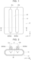
- adhesive 20 is applied to a surface of a case 14 of a battery pack 12, as shown in FIG. 1 .
- the adhesive 20 is applied to two application areas 21a, 21b that are spaced apart from each other in the x direction.
- the adhesive 20 is applied such that the adhesive 20 extends in a straight line in the y direction (i.e., the direction perpendicular to the x direction) in each of the application areas 21a, 21b.
- the adhesive 20 is applied such that the cross-sectional shape of the adhesive 20 is a generally circular shape.
- the adhesive 20 is jelly-like and has thixotropic properties.
- the thixotropic properties mean properties where the viscosity decreases in a condition where shear stress is applied, and the viscosity gradually increases in static conditions.
- ceramic powder is dispersed within the adhesive 20.
- the adhesive 20 in the application area 21a may be referred to as "adhesive 20a”
- the adhesive 20 in the application area 21b may be referred to as "adhesive 20b”.
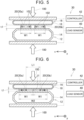
- the cooler 16 is placed above the battery pack 12, as shown in FIG. 3 .
- the cooler 16 is placed above the battery pack 12, such that the adhesive 20 is sandwiched between the case 14 of the battery pack 12 and an outer wall 18 of the cooler 16.
- the stiffness of the case 14 of the battery pack 12 is higher than that of the outer wall 18 of the cooler 16.
- the pressurization process is carried out.
- the cooler 16 is pressurized toward the battery pack 12 by the pressurizer 30 as indicated by arrows 100 in FIG. 4 .
- the adhesive 20 is compressed. Namely, the thickness t1 of the adhesive 20 is reduced.
- the pressurizer 30 has a load sensor 40 and a controller 42.
- the load sensor 40 detects the load N1 applied to the pressurizer 30 (namely, the load applied to the adhesive 20).
- the controller 42 controls the pressurizer 30 according to the detection value of the load sensor 40.
- the adhesive 20 is compressed while the load N1 applied to the pressurizer 30 is detected by the load sensor 40.
- the adhesive 20 As the adhesive 20 is compressed, the adhesive 20 flows in the x direction as indicated by arrows 102 in FIG. 5 . As a result, the width W1 of the adhesives 20a, 20b expands. As the adhesive 20 is further compressed from the state of FIG. 5 , the width W1 of the adhesives 20a, 20b further expands, and the adhesive 20a and the adhesive 20b contact with each other, as shown in FIG. 6 and FIG. 7 . In this manner, the adhesive 20a and the adhesive 20b are connected to each other, so that the adhesive 20 is spread over the entire major area of the surface of the case 14 (i.e., the area having the width W2 in FIG. 6 and FIG. 7 ).
- the pressurizer 30 compresses the adhesive 20 in such a manner that the load N1 applied to the pressurizer 30 (i.e., the load applied to the adhesive 20) can be changed.
- the pressurizer 30 compresses the adhesive 20 at a constant work rate or at a constant compression speed.
- the load N1 applied to the pressurizer 30 changes.
- FIG. 8 shows changes in the load N1 applied to the pressurizer 30 during the pressurization process.
- the load N1 applied to the pressurizer 30 at the start of the pressurization process is low.
- the adhesive 20a and the adhesive 20b are separated from each other as shown in FIG. 4 and FIG. 5 .
- the load required to expand the width W1 increases.
- the load N1 applied to the pressurizer 30 increases slowly in a curved line as the thickness t1 of the adhesive 20 decreases.
- the adhesive 20a and the adhesive 20b contact with each other as shown in FIG. 6 , the adhesives 20a, 20b become unable to flow in the x direction at the contact position J1.
- the load required to expand the width W2 of the adhesive 20 rapidly increases.
- the load N1 applied to the pressurizer 30 rises rapidly from the bending point P1.
- the adhesive 20 has the thixotropic properties.
- the viscosity of the adhesive 20 increases at around the contact position J1.
- the load N1 applied to the pressurizer 30 rises extremely steeply from the bending point P1.
- the period in which the load N1 increases slowly in a curved line will be referred to as “curvilinear increase period T1", and the period in which the load N1 increases rapidly will be referred to “rapid increase period T2".
- the load N1 increases at a higher rate of increase than the rate of increase of the load N1 in the curvilinear increase period T1.
- the load N1 increases in a polygonal line with respect to the trajectory of the load N1 in the curvilinear increase period T1. Namely, at the bending point PI, the load N1 changes in an indifferentiable manner.
- the adhesive 20a and the adhesive 20b are separated from each other during the curvilinear increase period T1, and the adhesive 20a and the adhesive 20b are connected to each other during the rapid increase period T2.
- the controller 42 of the pressurizer 30 monitors the detection value of the load sensor 40.
- the controller 42 stops pressurization by the pressurizer 30.
- the threshold value Nth is set to a value of the load N1 applied to the pressurizer 30 during the rapid increase period T2. Namely, the threshold value Nth is set to a higher value than the load N1 applied at the bending point P1.
- the adhesive 20a and the adhesive 20b are in contact with each other as shown in FIG. 6 and FIG. 7 .
- the adhesive 20a and the adhesive 20b contact with each other, by stopping the pressurization after the time of transition from the curvilinear increase period T1 to the rapid increase period T2. Then, the adhesive 20 is cured while a condition where the battery pack 12 and the cooler 16 are sandwiched by the pressurizer 30 is maintained. With the adhesive 20 thus cured, the battery pack 12 is bonded to the cooler 16. In this manner, the module of the battery pack 12 and the cooler 16 is completed.
- a value of the load N1 in the rapid increase period T2 is set as the threshold value Nth, and the pressurization is stopped when the detection value of the load sensor 40 reaches the threshold value Nth. Accordingly, the adhesive 20a in the application area 21a and the adhesive 20b in the application area 21b can be surely brought into contact with each other. During the pressurization process and after the pressurization process, it is impossible to visually determine whether the adhesive 20a and the adhesive 20b are in contact with each other. However, according to the above manufacturing method, it is possible to surely make the adhesive 20a and the adhesive 20b in contact with each other, without the need to visually check the adhesives 20a, 20b. Accordingly, with this manufacturing method, the gap 22 can be prevented from remaining between the adhesive 20a and the adhesive 20b, and shortage of the adhesive strength can be prevented.
- the cross-sectional area S1 of the adhesive 20 before compression is the sum of the cross-sectional area of the adhesive 20a and that of the adhesive 20b.
- R denotes the diameter of the cross section of each adhesive 20a, 20b shown in FIG. 2
- the distance L1 between the center of the adhesive 20a and the center of the adhesive 20b before compression is substantially equal to a half of the width W2 of the adhesive 20 after compression.
- W2t denotes the design value of the width W2
- t1t denotes the design value of the thickness t1
- the width W2 and thickness t1 of the adhesive 20 at the time when the load N1 rapidly increases substantially coincide with the width W2t and thickness t1t as designed. Accordingly, it is possible to make the width W2 and thickness t1 of the adhesive 20 substantially equal to the width W2t and thickness t1t as designed, by stopping the pressurization by the pressurizer 30 immediately after the transition from the curvilinear increase period T1 to the rapid increase period T2 as in the first embodiment.
- the width W2 and thickness t1 of the adhesive 20 after compression can be accurately controlled.
- the stiffness of the case 14 of the battery pack 12 is higher than that of the outer wall 18 of the cooler 16.
- concentration of the load in the pressurization process and shortage of the adhesive strength can be prevented.
- the case 14 is designed to have flat surfaces, the surface of the case 14 may be slightly distorted (e.g., warped) as shown in FIG. 9 .
- the outer wall 18 of the cooler 16 elastically deforms in accordance with the shape of the case 14 as shown in FIG. 9 in the pressurization process, since the stiffness of the outer wall 18 of the cooler 16 is lower than that of the case 14.
- the outer wall 18 is fixed in a deflected state to the case 14 because the adhesive strength of the adhesive 20 is stronger than the force with which the outer wall 18 tries to return to its original shape.
- the outer wall 18 is fixed in the shape that conforms to distortion of the case 14, so that the cooler 16 can be fixed to the case 14 with high strength.
- the ceramic powder is dispersed within the adhesive 20; therefore, the adhesive 20 has a high thermal conductivity. Accordingly, the battery pack 12 can be efficiently cooled by the cooler 16.
- a value of the load N1 during the rapid increase period T2 is set as the threshold value Nth, and the rapid increase period T2 is detected by checking whether the detection value of the load sensor 40 reaches the threshold value Nth.
- the rapid increase period T2 may be detected by another method. For example, the rate of increase of the load N1 may be calculated from the detection value of the load sensor 40, and the rapid increase period T2 may be detected based on the rate of increase of the load N1.
- the pressurization process is performed by using a pressurizer 30a shown in FIG. 10 .
- the pressurizer 30a of FIG. 10 has a compression speed sensor 44 in place of the load sensor 40.
- the other configuration of the pressurizer 30a of FIG. 10 is identical with that of the pressurizer 30 of FIG. 4 .
- the compression speed sensor 44 detects the compression speed V1 of the adhesive 20 in the pressurization process.
- the compression speed V1 is equal to the rate of reduction dt1/dt of the thickness t1 of the adhesive 20.
- the pressurizer 30 compresses the adhesive 20 in such a manner that the compression speed V1 can be changed.
- the pressurizer 30 compresses the adhesive 20 at a constant work rate or at a constant load.
- the compression speed V1 changes.
- FIG. 11 shows changes in the compression speed V1 during the compression process of the second embodiment.
- the compression speed V1 at the start of the pressurization process is high.
- the width W1 expands, and the load required to expand the W1 increases.
- the compression speed V1 decreases slowly in a curved line as the thickness t1 of the adhesive 20 decreases.
- the adhesives 20a, 20b stop flowing in the x direction at the contact position.
- the load required to expand the width W2 of the adhesive 20 rapidly increases.
- the compression speed V1 rapidly drops from the bending point P2 as shown in FIG. 11 .
- the adhesive 20 has the thixotropic properties; therefore, the compression speed V1 drops extremely steeply from the bending point P2.
- the period in which the compression speed V1 decreases slowly in a curved line will be referred to as “curvilinear decrease period T3”
- the period in which the compression speed V1 decreases rapidly will be referred to as "rapid decrease period T4".
- the rapid decrease period T4 the compression speed V1 decreases in a polygonal line with respect to the trajectory of the compression speed V1 in the curvilinear decrease period T3.
- the controller 42 of the pressurizer 30 monitors the detection value of the compression speed sensor 44.
- the controller 42 stops pressurization by the pressurizer 30.
- the threshold value Vth is set to a value of the compression speed V1 during the rapid decrease period T4. Namely, the threshold value Vth is set to a lower value than the compression speed V1 at the bending point P2.
- a value of the compression speed V1 during the rapid decrease period T4 is set as the threshold value Vth, and the rapid decrease period T4 is detected by checking whether the detection value of the compression speed sensor 44 is reduced to the threshold value Vth.
- the rapid decrease period T4 may be detected by another method. For example, the rate of reduction dV1/dt of the compression speed V1 may be calculated from the detection value of the compression speed sensor 44, and the rapid decrease period T4 may be detected based on the rate of reduction dV1/dt.
- the adhesive 20 is applied to the two application areas 21a, 21b.
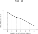
- the adhesive 20 may be distributed and applied to three or more application areas.
- FIG. 12 shows the value of the load N1 required to expand the adhesive 20 using the pressurizer over the same range as that of the first and second embodiments.
- the results of measurement of the required load N1 while the number "n" of the application areas is changed are indicated.
- the required load N1 can be reduced as the number "n" of the application areas increases.
Abstract
A method of manufacturing adhered components includes a process of applying adhesive (20, 20a, 20b) to application areas (21a, 21b) on a surface of a first component (12), a process of placing a second component (16) above the first component (12), and a process of pressurizing the second component (16) toward the first component (12). In the pressurization process, the load applied to a pressurizer (30) changes while sequentially undergoing a curvilinear increase period in which the load increases in a curved line as the compression amount of the adhesive (20, 20a, 20b) increases, and a rapid increase period in which the load increases in a polygonal line with respect to the trajectory of the load in the curvilinear increase period as the compression amount increases. During pressurization by the pressurizer (30), the load is detected by a load sensor (40), the rapid increase period is detected based on the detection value of the load sensor (40), and the pressurization is stopped during the rapid increase period.
Description
- The technology disclosed in the specification relates to a method of manufacturing adhered components.
-
Japanese Unexamined Patent Application Publication No. 2019-119147 JP 2019-119147 A - In the technology of
JP 2019-119147 A - A first method of manufacturing adhered components disclosed in the specification has an application process, a component placement process, and a pressurization process. In the application process, an adhesive is applied to a plurality of application areas extending linearly and spaced in a direction intersecting an extending direction in which the application areas extend linearly, on a surface of a first component. In the component placement process, a second component is placed above the first component such that the adhesive is sandwiched between the first component and the second component. In the pressurization process, a pressurizer pressurizes the second component toward the first component, to compress the adhesive. In the pressurization process, a load applied to the pressurizer changes such that the load goes through a curvilinear increase period in which the load increases in a curved line as an amount of compression of the adhesive increases, and a rapid increase period in which the load increases in a polygonal line with respect to a trajectory of the load in the curvilinear increase period as the amount of compression of the adhesive increases, in the order of description. The pressurization process includes performing pressurization by the pressurizer while detecting the load by a load sensor, detecting the rapid increase period based on a detection value of the load sensor, and stopping the pressurization by the pressurizer during the rapid increase period.
- In the manufacturing method, after the adhesive is applied to the application areas of the first component, and the second component is placed such that the adhesive is sandwiched between the first component and the second component, the pressurization process is performed. In the pressurization process, the pressurizer pressurizes the second component toward the first component to compress the adhesive, so that the adhesive expands in the lateral direction. While the adhesives on the application areas are not connected to each other, the load applied to the pressurizer increases in a curved line as the amount of compression of the adhesive increases. Namely, the period in which the adhesives are not connected to each other corresponds to the curvilinear increase period. Then, once the adhesives are connected to each other due to expansion of the adhesives, the adhesive is less likely or unlikely to flow in the lateral direction in an area where the adhesives are connected to each other. Thus, the adhesive is less likely or unlikely to be compressed, and the load applied to the pressurizer rapidly increases. At this time, the load applied to the pressurizer increases in a polygonal line with respect to the trajectory of the load in the curvilinear increase period. Namely, the period after the time when the adhesives are connected to each other corresponds to the rapid increase period. In this manufacturing method, the pressurizer performs pressurization while the load applied to the pressurizer is detected by the load sensor, the rapid increase period is detected based on the detection value of the load sensor, and the pressurization by the pressurizer is stopped during the rapid increase period. Accordingly, the pressurization can be stopped in a condition where the adhesives are connected to each other. Namely, according to the manufacturing method, the adhesives can be surely connected to each other during the pressurization process.
- A second method of manufacturing adhered components disclosed in the specification has an application process, a component placement process, and a pressurization process. In the application process, an adhesive is applied to a plurality of application areas extending linearly and spaced in a direction intersecting an extending direction in which the application areas extend linearly, on a surface of a first component. In the component placement process, a second component is placed above the first component such that the adhesive is sandwiched between the first component and the second component. In the pressurization process, a pressurizer pressurizes the second component toward the first component, to compress the adhesive. In the pressurization process, a compression speed of the adhesive changes such that the compression speed goes through a curvilinear decrease period in which the compression speed decreases in a curved line as an amount of compression of the adhesive increases, and a rapid decrease period in which the compression speed decreases in a polygonal line with respect to a trajectory of the compression speed in the curvilinear increase period as the amount of compression of the adhesive increases, in the order of description. The pressurization process includes performing pressurization by the pressurizer while detecting the compression speed by a compression speed sensor, detecting the rapid decrease period based on a detection value of the compression speed sensor, and stopping the pressurization by the pressurizer during the rapid decrease period.
- In the manufacturing method, after the adhesive is applied to the application areas of the first component, and the second component is placed such that the adhesive is sandwiched between the first component and the second component, the pressurization process is performed. In the pressurization process, the pressurizer pressurizes the second component toward the first component to compresses the adhesive, so that the adhesive expands in the lateral direction. While the adhesives on the application areas are not connected to each other, the compression speed of the adhesive decreases in a curved line as the amount of compression of the adhesive increases. Namely, the period in which the adhesives are not connected to each other corresponds to the curvilinear decrease period. Then, once the adhesives are connected to each other due to expansion of the adhesives, the adhesive is less likely or unlikely to flow in the lateral direction in an area where the adhesives are connected to each other. Thus, the adhesive is less likely or unlikely to be compressed, and the compression speed of the adhesive rapidly decreases. At this time, the compression speed of the adhesive decreases in a polygonal line with respect to the trajectory of the compression speed in the curvilinear decrease period. Namely, the period after the time when the adhesives are connected to each other corresponds to the rapid decrease period. In the manufacturing method, the pressurizer performs pressurization while the compression speed of the adhesive is detected by the compression speed sensor, the rapid decrease period is detected based on the detection value of the compression speed sensor, and the pressurization by the pressurizer is stopped during the rapid decrease period. Accordingly, the pressurization can be stopped in a condition where the adhesives are connected to each other. Namely, according to the manufacturing method, the adhesives can be surely connected to each other during the pressurization process.
- Features, advantages, and technical and industrial significance of exemplary embodiments of the invention will be described below with reference to the accompanying drawings, in which like signs denote like elements, and wherein:
-
FIG. 1 is a plan view showing an application process; -
FIG. 2 is a cross-sectional view showing the application process (a cross-sectional view taken along line II-II inFIG. 1 ); -
FIG. 3 is a cross-sectional view showing a component placement process; -
FIG. 4 is a cross-sectional view showing a compression process; -
FIG. 5 is a cross-sectional view showing the compression process; -
FIG. 6 is a cross-sectional view showing the compression process; -
FIG. 7 is a plan view showing the compression process; -
FIG. 8 is a graph showing changes in the load in the compression process; -
FIG. 9 is a cross-sectional view showing the compression process; -
FIG. 10 is a cross-sectional view showing the compression process; -
FIG. 11 is a graph showing changes in the compression speed in the compression process; and -
FIG. 12 is a graph showing the relationship between the number of application areas and the load required during compression. - In one example of the first manufacturing method described above, in the pressurization process, the pressurization by the pressurizer may be stopped when the detection value of the load sensor reaches a threshold value. The threshold value may be set to a value of the load during the rapid increase period.
- With this arrangement, the pressurization by the pressurizer can be stopped during the rapid increase period.
- In one example of the first manufacturing method described above, the adhesive may have thixotropic properties.
- With this arrangement, the viscosity of the adhesive increases when the adhesives are connected to each other; therefore, the load applied to the pressurizer rises more sharply during the rapid increase period. Accordingly, the rapid increase period can be easily detected.
- In one example of the first manufacturing method described above, the first component may be a battery pack, and the second component may be a cooler.
- In one example of the first manufacturing method described above, the stiffness of one of the first component and the second component may be lower than the stiffness of the other of the first component and the second component.
- With this arrangement, when the component having the higher stiffness is distorted, the component having the lower stiffness can deform according to the distortion. Accordingly, the components are likely to be more properly bonded together.
- In one example of the first manufacturing method described above, ceramic powder may be dispersed in the adhesive.
- With this arrangement, the thermal conductivity of the adhesive can be improved.
- In the following description, a method of manufacturing a module of a battery pack for an electrified vehicle and a cooler, by bonding the cooler to the battery pack.
- In a manufacturing method of a first embodiment, an adhesive application process, a component placement process, and a pressurization process are carried out in this order.
- In the adhesive application process, adhesive 20 is applied to a surface of a
case 14 of abattery pack 12, as shown inFIG. 1 . The adhesive 20 is applied to twoapplication areas application areas FIG. 2 , the adhesive 20 is applied such that the cross-sectional shape of the adhesive 20 is a generally circular shape. The adhesive 20 is jelly-like and has thixotropic properties. In this specification, the thixotropic properties mean properties where the viscosity decreases in a condition where shear stress is applied, and the viscosity gradually increases in static conditions. Also, ceramic powder is dispersed within the adhesive 20. In the following description, the adhesive 20 in theapplication area 21a may be referred to as "adhesive 20a", and the adhesive 20 in theapplication area 21b may be referred to as "adhesive 20b". In the conditions ofFIG. 1 and FIG. 2 , there is agap 22 between the adhesive 20a and the adhesive 20b. - Then, in the component placement process, the cooler 16 is placed above the
battery pack 12, as shown inFIG. 3 . The cooler 16 is placed above thebattery pack 12, such that the adhesive 20 is sandwiched between thecase 14 of thebattery pack 12 and anouter wall 18 of the cooler 16. The stiffness of thecase 14 of thebattery pack 12 is higher than that of theouter wall 18 of the cooler 16. - Then, the pressurization process is carried out. In the pressurization process, the cooler 16 is pressurized toward the
battery pack 12 by the pressurizer 30 as indicated byarrows 100 inFIG. 4 . As a result, the adhesive 20 is compressed. Namely, the thickness t1 of the adhesive 20 is reduced. As shown inFIG. 4 , thepressurizer 30 has aload sensor 40 and acontroller 42. Theload sensor 40 detects the load N1 applied to the pressurizer 30 (namely, the load applied to the adhesive 20). Thecontroller 42 controls the pressurizer 30 according to the detection value of theload sensor 40. In the pressurization process, the adhesive 20 is compressed while the load N1 applied to thepressurizer 30 is detected by theload sensor 40. As the adhesive 20 is compressed, the adhesive 20 flows in the x direction as indicated byarrows 102 inFIG. 5 . As a result, the width W1 of theadhesives FIG. 5 , the width W1 of theadhesives FIG. 6 andFIG. 7 . In this manner, the adhesive 20a and the adhesive 20b are connected to each other, so that the adhesive 20 is spread over the entire major area of the surface of the case 14 (i.e., the area having the width W2 inFIG. 6 andFIG. 7 ). - In the pressurization process, the
pressurizer 30 compresses the adhesive 20 in such a manner that the load N1 applied to the pressurizer 30 (i.e., the load applied to the adhesive 20) can be changed. For example, thepressurizer 30 compresses the adhesive 20 at a constant work rate or at a constant compression speed. Thus, during the pressurization process, the load N1 applied to the pressurizer 30 changes. -
FIG. 8 shows changes in the load N1 applied to the pressurizer 30 during the pressurization process. As shown inFIG. 8 , the load N1 applied to the pressurizer 30 at the start of the pressurization process is low. Immediately after the start of the pressurization process, the adhesive 20a and the adhesive 20b are separated from each other as shown inFIG. 4 andFIG. 5 . In this condition, as the width W1 of each adhesive 20a, 20b expands, the load required to expand the width W1 increases. Thus, as shown inFIG. 8 , immediately after the start of the pressurization process, the load N1 applied to the pressurizer 30 increases slowly in a curved line as the thickness t1 of the adhesive 20 decreases. Then, when the adhesive 20a and the adhesive 20b contact with each other as shown inFIG. 6 , theadhesives FIG. 8 , the load N1 applied to the pressurizer 30 rises rapidly from the bending point P1. In the first embodiment, in particular, the adhesive 20 has the thixotropic properties. Thus, when the adhesive 20 stops flowing in the x direction at the contact position J1, the viscosity of the adhesive 20 increases at around the contact position J1. Thus, the load N1 applied to the pressurizer 30 rises extremely steeply from the bending point P1. In the following description, the period in which the load N1 increases slowly in a curved line will be referred to as "curvilinear increase period T1", and the period in which the load N1 increases rapidly will be referred to "rapid increase period T2". In the rapid increase period T2, the load N1 increases at a higher rate of increase than the rate of increase of the load N1 in the curvilinear increase period T1. In the rapid increase period T2, the load N1 increases in a polygonal line with respect to the trajectory of the load N1 in the curvilinear increase period T1. Namely, at the bending point PI, the load N1 changes in an indifferentiable manner. As described above, the adhesive 20a and the adhesive 20b are separated from each other during the curvilinear increase period T1, and the adhesive 20a and the adhesive 20b are connected to each other during the rapid increase period T2. - During the pressurization process, the
controller 42 of the pressurizer 30 monitors the detection value of theload sensor 40. When the detection value of theload sensor 40 reaches a threshold value Nth shown inFIG. 8 , thecontroller 42 stops pressurization by thepressurizer 30. The threshold value Nth is set to a value of the load N1 applied to the pressurizer 30 during the rapid increase period T2. Namely, the threshold value Nth is set to a higher value than the load N1 applied at the bending point P1. Thus, at the time when thecontroller 42 stops pressurization (namely, at the time when the load N1 reaches the threshold value Nth), the adhesive 20a and the adhesive 20b are in contact with each other as shown inFIG. 6 andFIG. 7 . Thus, it is possible to surely make the adhesive 20a and the adhesive 20b contact with each other, by stopping the pressurization after the time of transition from the curvilinear increase period T1 to the rapid increase period T2. Then, the adhesive 20 is cured while a condition where thebattery pack 12 and the cooler 16 are sandwiched by thepressurizer 30 is maintained. With the adhesive 20 thus cured, thebattery pack 12 is bonded to the cooler 16. In this manner, the module of thebattery pack 12 and the cooler 16 is completed. - As described above, in the manufacturing method of the first embodiment, a value of the load N1 in the rapid increase period T2 is set as the threshold value Nth, and the pressurization is stopped when the detection value of the
load sensor 40 reaches the threshold value Nth. Accordingly, the adhesive 20a in theapplication area 21a and the adhesive 20b in theapplication area 21b can be surely brought into contact with each other. During the pressurization process and after the pressurization process, it is impossible to visually determine whether the adhesive 20a and the adhesive 20b are in contact with each other. However, according to the above manufacturing method, it is possible to surely make the adhesive 20a and the adhesive 20b in contact with each other, without the need to visually check theadhesives gap 22 can be prevented from remaining between the adhesive 20a and the adhesive 20b, and shortage of the adhesive strength can be prevented. - The cross-sectional area S1 of the adhesive 20 before compression is the sum of the cross-sectional area of the adhesive 20a and that of the adhesive 20b. Where R denotes the diameter of the cross section of each adhesive 20a, 20b shown in
FIG. 2 , the cross-sectional area S1 satisfies the relationship that S1=2×π×(R/2)2. As is apparent fromFIG. 6 , the cross-sectional area S2 of the adhesive 20 after compression satisfies the relationship that S2=W2×t1. The cross-sectional area S1 of the adhesive 20 before compression is substantially equal to the cross-sectional area S2 of the adhesive 20 after compression. Accordingly, the relationship that R=((4×W2×t1)/ (2×π))1/2 is established. As is apparent fromFIG. 2 andFIG. 6 , the distance L1 between the center of the adhesive 20a and the center of the adhesive 20b before compression is substantially equal to a half of the width W2 of the adhesive 20 after compression. Namely, the relationship that L1=W2/2 is established. Accordingly, where W2t denotes the design value of the width W2, and t1t denotes the design value of the thickness t1, the distance L1 and the diameter R at the time of application of the adhesive 20 can be set to satisfy the relationships that L1=W2t/2, and R=((4×W2×t1t)/(2×π))1/2. With the distance L1 and the diameter R set in this manner, the width W2 and thickness t1 of the adhesive 20 at the time when the load N1 rapidly increases (i.e., at the bending point PI) substantially coincide with the width W2t and thickness t1t as designed. Accordingly, it is possible to make the width W2 and thickness t1 of the adhesive 20 substantially equal to the width W2t and thickness t1t as designed, by stopping the pressurization by the pressurizer 30 immediately after the transition from the curvilinear increase period T1 to the rapid increase period T2 as in the first embodiment. Thus, according to the manufacturing method of the first embodiment, the width W2 and thickness t1 of the adhesive 20 after compression can be accurately controlled. - In the first embodiment, the stiffness of the
case 14 of thebattery pack 12 is higher than that of theouter wall 18 of the cooler 16. Thus, concentration of the load in the pressurization process and shortage of the adhesive strength can be prevented. Namely, while thecase 14 is designed to have flat surfaces, the surface of thecase 14 may be slightly distorted (e.g., warped) as shown inFIG. 9 . In this case, theouter wall 18 of the cooler 16 elastically deforms in accordance with the shape of thecase 14 as shown inFIG. 9 in the pressurization process, since the stiffness of theouter wall 18 of the cooler 16 is lower than that of thecase 14. Thus, even in the case where the surface of thecase 14 is distorted, high load can be prevented from being locally applied to a part of thecase 14 and a part of theouter wall 18. When the adhesive 20 is cured under this condition, theouter wall 18 is fixed in a deflected state to thecase 14 because the adhesive strength of the adhesive 20 is stronger than the force with which theouter wall 18 tries to return to its original shape. Thus, theouter wall 18 is fixed in the shape that conforms to distortion of thecase 14, so that the cooler 16 can be fixed to thecase 14 with high strength. - In the first embodiment, the ceramic powder is dispersed within the adhesive 20; therefore, the adhesive 20 has a high thermal conductivity. Accordingly, the
battery pack 12 can be efficiently cooled by the cooler 16. - In the first embodiment, a value of the load N1 during the rapid increase period T2 is set as the threshold value Nth, and the rapid increase period T2 is detected by checking whether the detection value of the
load sensor 40 reaches the threshold value Nth. However, the rapid increase period T2 may be detected by another method. For example, the rate of increase of the load N1 may be calculated from the detection value of theload sensor 40, and the rapid increase period T2 may be detected based on the rate of increase of the load N1. - Next, a manufacturing method of a second embodiment will be described. In the manufacturing method of the second embodiment, too, the adhesive application process and the component placement process are performed in the same manner as in the first embodiment. In the second embodiment, the pressurization process is performed by using a
pressurizer 30a shown inFIG. 10 . The pressurizer 30a ofFIG. 10 has acompression speed sensor 44 in place of theload sensor 40. The other configuration of the pressurizer 30a ofFIG. 10 is identical with that of thepressurizer 30 ofFIG. 4 . Thecompression speed sensor 44 detects the compression speed V1 of the adhesive 20 in the pressurization process. The compression speed V1 is equal to the rate of reduction dt1/dt of the thickness t1 of the adhesive 20. In the pressurization process of the second embodiment, thepressurizer 30 compresses the adhesive 20 in such a manner that the compression speed V1 can be changed. For example, thepressurizer 30 compresses the adhesive 20 at a constant work rate or at a constant load. Thus, during the pressurization process, the compression speed V1 changes. -
FIG. 11 shows changes in the compression speed V1 during the compression process of the second embodiment. As shown inFIG. 11 , the compression speed V1 at the start of the pressurization process is high. As the thickness t1 of the adhesive 20a, 20b decreases, the width W1 expands, and the load required to expand the W1 increases. Thus, immediately after the start of the pressurization process, the compression speed V1 decreases slowly in a curved line as the thickness t1 of the adhesive 20 decreases. Then, when the adhesive 20a and the adhesive 20b contact with each other, theadhesives FIG. 11 . In particular, the adhesive 20 has the thixotropic properties; therefore, the compression speed V1 drops extremely steeply from the bending point P2. In the following description, the period in which the compression speed V1 decreases slowly in a curved line will be referred to as "curvilinear decrease period T3", and the period in which the compression speed V1 decreases rapidly will be referred to as "rapid decrease period T4". In the rapid decrease period T4, the compression speed V1 decreases in a polygonal line with respect to the trajectory of the compression speed V1 in the curvilinear decrease period T3. - During the pressurization process, the
controller 42 of the pressurizer 30 monitors the detection value of thecompression speed sensor 44. When the detection value of thecompression speed sensor 44 decreases to a threshold value Vth shown inFIG. 11 , thecontroller 42 stops pressurization by thepressurizer 30. The threshold value Vth is set to a value of the compression speed V1 during the rapid decrease period T4. Namely, the threshold value Vth is set to a lower value than the compression speed V1 at the bending point P2. Thus, at the time when thecontroller 42 stops pressurization (namely, at the time when the compression speed V1 decreases to the threshold value Vth), the adhesive 20a and the adhesive 20b are in contact with each other. Thus, it is possible to surely make the adhesive 20a and the adhesive 20b in contact with each other, by stopping the pressurization after the time of transition from the curvilinear decrease period T3 to the rapid decrease period T4. Then, the adhesive 20 is cured so that thecase 14 is bonded to the cooler 16. In this manner, the module of thebattery pack 12 and the cooler 16 is completed. - As described above, in the manufacturing method of the second embodiment, too, the adhesive 20a and the adhesive 20b can be surely brought into contact with each other. In the second embodiment, a value of the compression speed V1 during the rapid decrease period T4 is set as the threshold value Vth, and the rapid decrease period T4 is detected by checking whether the detection value of the
compression speed sensor 44 is reduced to the threshold value Vth. However, the rapid decrease period T4 may be detected by another method. For example, the rate of reduction dV1/dt of the compression speed V1 may be calculated from the detection value of thecompression speed sensor 44, and the rapid decrease period T4 may be detected based on the rate of reduction dV1/dt. - In the first and second embodiments, the adhesive 20 is applied to the two
application areas FIG. 12 shows the value of the load N1 required to expand the adhesive 20 using the pressurizer over the same range as that of the first and second embodiments. InFIG. 12 , the results of measurement of the required load N1 while the number "n" of the application areas is changed are indicated. As shown inFIG. 12 , the required load N1 can be reduced as the number "n" of the application areas increases. When the number of the application areas is larger than two, the distance L1 and diameter R of theadhesives 20 when applied can be set to satisfy the relationships that L1=W2t/n, and R=((4×W2t×t1t)/ (n ×π))1/2, and the thickness t1 and width W2 of the adhesive 20 after compression can be accurately controlled to the design values. - While the embodiments have been described in detail, these embodiments are merely exemplary, and do not limit the appended claims. The technologies described in the claims include those obtained by modifying or changing the illustrated specific examples in various ways. The technical elements described in the specification or drawings exhibit the technical usefulness alone or in various combinations, and are not limited to the combinations described in the claims as filed. The technologies illustrated in the specification or drawings achieve two or more objects at the same time, and have the technical usefulness if they achieve one of the objects.
Claims (9)
- A method of manufacturing adhered components, comprising:a first process of applying an adhesive (20, 20a, 20b) to a plurality of application areas (21a, 21b) on a surface of a first component (12), the application areas extending linearly and being spaced in a direction intersecting an extending direction in which the application areas extend linearly;a second process of placing a second component (16) above the first component (12) such that the adhesive (20, 20a, 20b) is sandwiched between the first component (12) and the second component (16); anda third process of compressing the adhesive (20, 20a, 20b) by pressurizing the second component (16) toward the first component (12) with a pressurizer (30),wherein, in the third process, a load applied to the pressurizer (30) changes such that the load goes through a curvilinear increase period and a rapid increase period in an order of description, the curvilinear increase period being a period in which the load increases in a curved line as an amount of compression of the adhesive (20, 20a, 20b) increases, the rapid increase period being a period in which the load increases in a polygonal line with respect to a trajectory of the load in the curvilinear increase period as the amount of compression of the adhesive increases, andwherein the third process includes performing pressurization by the pressurizer (30) while detecting the load by a load sensor (40), detecting the rapid increase period based on a detection value of the load sensor (40), and stopping the pressurization by the pressurizer during the rapid increase period.
- The method according to claim 1, wherein:in the third process, the pressurization by the pressurizer (30) is stopped when the detection value of the load sensor (40) reaches a threshold value; andthe threshold value is set to a value of the load during the rapid increase period.
- The method according to claim 1 or 2, wherein the adhesive (20, 20a, 20b) has thixotropic properties.
- The method according to any one of claims 1 to 3, wherein:the first component is a battery pack (12); andthe second component is a cooler (16).
- The method according to any one of claims 1 to 4, wherein a stiffness of one of the first component (12) and the second component (16) is lower than the stiffness of the other of the first component and the second component.
- The method according to any one of claims 1 to 5, wherein ceramic powder is dispersed in the adhesive (20, 20a, 20b).
- A method of manufacturing adhered components, comprising:a first process of applying an adhesive (20, 20a, 20b) to a plurality of application areas (21a, 21b) on a surface of a first component (12), the application areas extending linearly and being spaced in a direction intersecting an extending direction in which the application areas extend linearly;a second process of placing a second component (16) above the first component (12) such that the adhesive (20, 20a, 20b) is sandwiched between the first component (12) and the second component (16); anda third process of compressing the adhesive (20, 20a, 20b) by pressurizing the second component (16) toward the first component (12) with a pressurizer (30a),wherein, in the third process, a compression speed of the adhesive (20, 20a, 20b) changes such that the compression speed goes through a curvilinear decrease period and a rapid decrease period in an order of description, the curvilinear decrease period being a period in which the compression speed decreases in a curved line as an amount of compression of the adhesive (20, 20a, 20b) increases, the rapid decrease period being a period in which the compression speed decreases in a polygonal line with respect to a trajectory of the compression speed in the curvilinear decrease period as the amount of compression of the adhesive increases, andwherein the third process includes performing pressurization by the pressurizer (30a) while detecting the compression speed by a compression speed sensor (44), detecting the rapid decrease period based on a detection value of the compression speed sensor (44), and stopping the pressurization by the pressurizer during the rapid decrease period.
- A method of manufacturing adhered components, comprising:a first process of placing an adhesive (20, 20a, 20b) on a plurality of application areas (21a, 21b) extending linearly and spaced in a direction intersecting an extending direction in which the application areas extend linearly, between a first component (12) and a second component (16); anda second process of compressing the adhesive (20, 20a, 20b) by pressurizing the adhesive between the second component (16) and the first component (12) with a pressurizer (30),wherein, in the second process, a load applied to the pressurizer (30) changes such that the load goes through a first increase period and a second increase period in an order of description, the first increase period being a period in which the load increases as an amount of compression of the adhesive (20, 20a, 20b) increases, the second increase period being a period in which (i) the load increases in a polygonal line with respect to a trajectory of the load in the first increase period as the amount of compression of the adhesive increases, and (ii) a rate of increase of the load is higher than the rate of increase of the load in the first increase period, andwherein the second process includes performing pressurization by the pressurizer (30) while detecting the load by a load sensor (40), detecting the second increase period based on a detection value of the load sensor (40), and stopping the pressurization by the pressurizer during the second increase period.
- A method of manufacturing adhered components, comprising:a first process of placing an adhesive (20, 20a, 20b) on a plurality of application areas (21a, 21b) extending linearly and spaced in a direction intersecting an extending direction in which the application areas extend linearly, between a first component (12) and a second component (16); anda second process of compressing the adhesive (20, 20a, 20b) by pressurizing the adhesive between the second component (16) and the first component (12) with a pressurizer (30a),wherein, in the second process, a compression speed of the adhesive (20, 20a, 20b) changes such that the compression speed goes through a first decrease period and a second decrease period in an order of description, the first decrease period being a period in which the compression speed decreases as an amount of compression of the adhesive (20, 20a, 20b) increases, the second decrease period being a period in which (i) the compression speed decreases in a polygonal line with respect to a trajectory of the compression speed in the first decrease period as the amount of compression of the adhesive increases, and (ii) a rate of decrease of the compression speed of the adhesive is higher than the rate of decrease of the compression speed of the adhesive in the first decrease period, andwherein the second process includes performing pressurization by the pressurizer (30a) while detecting the compression speed by a compression speed sensor (44), detecting the second decrease period based on a detection value of the compression speed sensor (44), and stopping the pressurization by the pressurizer during the second decrease period.
Applications Claiming Priority (1)
| Application Number | Priority Date | Filing Date | Title |
|---|---|---|---|
| JP2021127426A JP2023022518A (en) | 2021-08-03 | 2021-08-03 | Method of manufacturing adhesive component |
Publications (1)
| Publication Number | Publication Date |
|---|---|
| EP4129635A1 true EP4129635A1 (en) | 2023-02-08 |
Family
ID=82748414
Family Applications (1)
| Application Number | Title | Priority Date | Filing Date |
|---|---|---|---|
| EP22181665.5A Pending EP4129635A1 (en) | 2021-08-03 | 2022-06-28 | Method of manufacturing adhered components |
Country Status (4)
| Country | Link |
|---|---|
| US (1) | US20230038777A1 (en) |
| EP (1) | EP4129635A1 (en) |
| JP (1) | JP2023022518A (en) |
| CN (1) | CN115923158A (en) |
Citations (3)
| Publication number | Priority date | Publication date | Assignee | Title |
|---|---|---|---|---|
| JP2018079606A (en) * | 2016-11-15 | 2018-05-24 | アルプス電気株式会社 | Joined member, method for manufacturing joined member, hollow member, electronic/electric component, sensor housing and sensor |
| JP2019119147A (en) | 2018-01-09 | 2019-07-22 | 本田技研工業株式会社 | Manufacturing method of resin-reinforced metallic part |
| WO2021022125A1 (en) * | 2019-07-31 | 2021-02-04 | Lord Corporation | Methods and systems for reducing adhesive strength and associated pull-off stresses |
-
2021
- 2021-08-03 JP JP2021127426A patent/JP2023022518A/en active Pending
-
2022
- 2022-06-24 CN CN202210727457.7A patent/CN115923158A/en active Pending
- 2022-06-28 EP EP22181665.5A patent/EP4129635A1/en active Pending
- 2022-06-30 US US17/854,346 patent/US20230038777A1/en active Pending
Patent Citations (3)
| Publication number | Priority date | Publication date | Assignee | Title |
|---|---|---|---|---|
| JP2018079606A (en) * | 2016-11-15 | 2018-05-24 | アルプス電気株式会社 | Joined member, method for manufacturing joined member, hollow member, electronic/electric component, sensor housing and sensor |
| JP2019119147A (en) | 2018-01-09 | 2019-07-22 | 本田技研工業株式会社 | Manufacturing method of resin-reinforced metallic part |
| WO2021022125A1 (en) * | 2019-07-31 | 2021-02-04 | Lord Corporation | Methods and systems for reducing adhesive strength and associated pull-off stresses |
Also Published As
| Publication number | Publication date |
|---|---|
| CN115923158A (en) | 2023-04-07 |
| US20230038777A1 (en) | 2023-02-09 |
| JP2023022518A (en) | 2023-02-15 |
Similar Documents
| Publication | Publication Date | Title |
|---|---|---|
| Chen et al. | Mechanical behavior and progressive failure analysis of riveted, bonded and hybrid joints with CFRP-aluminum dissimilar materials | |
| Campilho et al. | Stress and failure analyses of scarf repaired CFRP laminates using a cohesive damage model | |
| EP3098061B1 (en) | Vehicle member joining structure | |
| EP2757027B1 (en) | Bonding with adhesive beads or plots | |
| US9759247B2 (en) | Structural component | |
| EP3268622B1 (en) | Thermally activated, shape configuable mechanical locking z-pin | |
| US20140318687A1 (en) | Multi-material joints and methods | |
| CN101678891B (en) | Reinforced panel | |
| EP4129635A1 (en) | Method of manufacturing adhered components | |
| JP6577608B2 (en) | Manufacturing method of resin reinforced metal parts | |
| US10048180B2 (en) | Coating bond test method and method of making a specimen for testing bond strength of a coating | |
| US20120246937A1 (en) | Method for enhancing the fatigue life of a structure | |
| US8455085B2 (en) | Metal/composite joint with selective interlaminar reinforcement | |
| US10464282B2 (en) | Systems and processes for joining workpieces robustly using moguls and adhesive | |
| KR20160102051A (en) | A pre-stressing device, and a method for reinforcing a structural member | |
| CN112077584A (en) | Method for assembling bolt connection of composite material component | |
| CN113654983B (en) | Device and method for testing cementing property of T-direction surface and rigid structure of paper honeycomb | |
| DE102021108092A1 (en) | Pressure tool, pressing device and method for welding plastic components | |
| JP3106850U (en) | Specimen holding jig for shear test | |
| US10722936B2 (en) | Rivet bonding workpiece stack-ups having one or more polymer composite workpieces | |
| KR20190066340A (en) | Repair fastener for composite materials delamination and the methods using the device | |
| US20220403866A1 (en) | Pre-fixing two substrates | |
| JPH10227151A (en) | Vibration isolation device and manufacture thereof | |
| JP2019002554A (en) | Method of fastening frp, frp fastening structure and structural member for elevator | |
| KR20240047681A (en) | Integrated load pad for aircraft structural testing |
Legal Events
| Date | Code | Title | Description |
|---|---|---|---|
| PUAI | Public reference made under article 153(3) epc to a published international application that has entered the european phase |
Free format text: ORIGINAL CODE: 0009012 |
|
| STAA | Information on the status of an ep patent application or granted ep patent |
Free format text: STATUS: REQUEST FOR EXAMINATION WAS MADE |
|
| 17P | Request for examination filed |
Effective date: 20220714 |
|
| AK | Designated contracting states |
Kind code of ref document: A1 Designated state(s): AL AT BE BG CH CY CZ DE DK EE ES FI FR GB GR HR HU IE IS IT LI LT LU LV MC MK MT NL NO PL PT RO RS SE SI SK SM TR |