EP4129567A1 - Machine for machining workpieces, with a blowing device - Google Patents
Machine for machining workpieces, with a blowing device Download PDFInfo
- Publication number
- EP4129567A1 EP4129567A1 EP22187144.5A EP22187144A EP4129567A1 EP 4129567 A1 EP4129567 A1 EP 4129567A1 EP 22187144 A EP22187144 A EP 22187144A EP 4129567 A1 EP4129567 A1 EP 4129567A1
- Authority
- EP
- European Patent Office
- Prior art keywords
- cylinder
- machine
- tool
- chips
- blowing device
- Prior art date
- Legal status (The legal status is an assumption and is not a legal conclusion. Google has not performed a legal analysis and makes no representation as to the accuracy of the status listed.)
- Granted
Links
Images


Classifications
-
- B—PERFORMING OPERATIONS; TRANSPORTING
- B23—MACHINE TOOLS; METAL-WORKING NOT OTHERWISE PROVIDED FOR
- B23Q—DETAILS, COMPONENTS, OR ACCESSORIES FOR MACHINE TOOLS, e.g. ARRANGEMENTS FOR COPYING OR CONTROLLING; MACHINE TOOLS IN GENERAL CHARACTERISED BY THE CONSTRUCTION OF PARTICULAR DETAILS OR COMPONENTS; COMBINATIONS OR ASSOCIATIONS OF METAL-WORKING MACHINES, NOT DIRECTED TO A PARTICULAR RESULT
- B23Q11/00—Accessories fitted to machine tools for keeping tools or parts of the machine in good working condition or for cooling work; Safety devices specially combined with or arranged in, or specially adapted for use in connection with, machine tools
- B23Q11/0042—Devices for removing chips
- B23Q11/006—Devices for removing chips by sucking and blowing simultaneously
-
- B—PERFORMING OPERATIONS; TRANSPORTING
- B27—WORKING OR PRESERVING WOOD OR SIMILAR MATERIAL; NAILING OR STAPLING MACHINES IN GENERAL
- B27F—DOVETAILED WORK; TENONS; SLOTTING MACHINES FOR WOOD OR SIMILAR MATERIAL; NAILING OR STAPLING MACHINES
- B27F1/00—Dovetailed work; Tenons; Making tongues or grooves; Groove- and- tongue jointed work; Finger- joints
- B27F1/02—Making tongues or grooves, of indefinite length
-
- B—PERFORMING OPERATIONS; TRANSPORTING
- B27—WORKING OR PRESERVING WOOD OR SIMILAR MATERIAL; NAILING OR STAPLING MACHINES IN GENERAL
- B27D—WORKING VENEER OR PLYWOOD
- B27D5/00—Other working of veneer or plywood specially adapted to veneer or plywood
- B27D5/003—Other working of veneer or plywood specially adapted to veneer or plywood securing a veneer strip to a panel edge
Definitions
- the present invention relates to a machine for machining workpieces made of in wood, ceramic, plastic, metal, glass, fiberglass, and the like.
- the invention relates to a machine of the above type, designed and manufactured in particular to make grooves on wooden workpieces.
- This machining can be carried out in an edge-banding machine, in a moulder machine, or in other types of pass-through machines.
- machines comprising a rotary tool, such as for example a blade or a milling cutter, which makes a groove on the workpiece parallel to the advancement direction, and a suction hood, to suck up the chip or dust resulting from the machining.
- a rotary tool such as for example a blade or a milling cutter, which makes a groove on the workpiece parallel to the advancement direction, and a suction hood, to suck up the chip or dust resulting from the machining.
- Rotary tools can make grooves in favor of advancement, that is, rotating in a way that is integral to the advancement of the piece, or against advancement, that is, rotating in the opposite direction to the advancement of the piece.
- the chip jet is directed downstream of the tool with respect to the advancement direction.
- an object of the present invention providing a machine for working workpieces made of wood, ceramic, plastic, metal, glass, fiberglass, and the like, which allows containing and sucking the resulting chip from optimal working.
- a machine for machining workpieces made of wood, ceramic, plastic, metal, glass, fiberglass, and the like comprising at least one tool, capable of performing machining on the surface of said workpiece, in such a way to create a jet of chips essentially oriented along an expulsion direction having an expulsion speed, wherein said machine is characterized in that it comprises a blowing device, placed after said tool with respect to said expulsion direction, capable of generating an air flow to reduce the expulsion speed of said jet of chips.
- said machine may comprise advancing means, to allow the advancement of said workpieces to be machined along an advancement direction, parallel to an advancement axis, and said advancement direction may be synchronous with said expulsion direction.
- said tool may be a blade.
- said tool may be capable of rotating with said advancement direction of said workpiece around an axis parallel to a horizontal axis, perpendicular to said perpendicular plane, and it is capable of translating along an axis parallel to said axis and along an axis parallel to said horizontal axis.
- said blowing device may comprise at least one nozzle from which said air flow comes out, and moving means, capable of moving said nozzle in such a way to intercept said jet of chips.
- said blowing device comprises a rotating selector, capable of letting out said air flow in such a way to intercept said jet of chips, and moving means, capable of allowing the rotation of said rotating selector.
- said rotating selector may comprise a hollow first cylinder, having a longitudinal through eyelet, on its lateral surface, oriented towards the workpiece; and a hollow second cylinder, placed inside said first cylinder and free to rotate with respect to said first cylinder, through which compressed air can flow, and comprising a plurality of openings, placed along its external surface, capable of creating a fluidic connection between the inside of said second cylinder and the outside, such that, when said second cylinder rotates with respect to said first cylinder, a portion of said longitudinal eyelet is selected to let through said air flow passing through the opening placed by said longitudinal eyelet.
- said rotating selector may comprise a hollow second cylinder, having a longitudinal through eyelet, on its lateral surface, oriented towards the workpiece; and a hollow first cylinder, placed outside said second cylinder and free to rotate with respect to said second cylinder, comprising a plurality of openings, placed along its external surface, capable of creating a fluidic connection between the inside of said first cylinder and the outside, such that, when said first cylinder rotates with respect to said second cylinder, a portion of said longitudinal eyelet is selected to let through said air flow passing through the opening placed by said longitudinal eyelet.
- said machine may comprise an enclosure and said tool and said blowing device may be housed within said enclosure.
- said enclosure may comprise suction means, capable of sucking said chips, and a suction duct, connected to said suction means, capable of directing said chips towards said suction means, and said blowing device may be capable of generating an air flow to direct said chips towards said suction duct.
- said machine may comprise an edge bander group placed before or after said tool.
- said machine M mainly comprises a tool 1, advancing means (not shown in the figures), for advancing the workpiece P to be machined, a blowing device 2, and an enclosure 3.
- the advancing means allow the advancement of the workpiece P to be machined according to an advancement direction W, parallel to an advancement axis X.
- the tool 1 is arranged on a plane parallel to a perpendicular plane XY, identified, in its turn, by said advancement axis X and from an axis Y, the latter perpendicular to the surface of said workpiece P.
- the blowing device 2 is arranged downstream of said tool 1, with respect to said advancement direction W.
- the enclosure 3 encloses said tool 1 and said blowing device 2.
- Said workpiece P to be machined can be, for example, a panel, as shown in the figures.
- Said tool 1 is of the rotary type, such as for example a blade or a cutter, and is able to rotate around an axis parallel to a horizontal axis Z, perpendicular to said perpendicular plane XY.
- the tool 1 is also able to translate along an axis parallel to said axis Y, and along an axis parallel to said horizontal axis Z.
- Said tool 1 can rotate around an axis parallel to said advancement axis X, so as to tilt with respect to said workpiece P.
- Said tool 1 is able to perform machining, such as grooves or incisions, on the surface of said workpiece P.
- said tool 1 is capable of rotating around said horizontal axis Z in favor of the advancement of said piece P, i.e. in such a way that its peripheral speed in proximity to said workpiece P is integral with said advancement direction W.
- said tool 1 During the execution of the machining operations on said workpiece P, said tool 1 generates a chip jet having an expulsion speed, which is concordant with said advancement direction W.
- the blowing device 2 generates an airflow to reduce the expulsion speed of said chip jet.
- said blowing device 2 is arranged inside said enclosure 3 at the maximum distance allowed by said tool 1.
- the air flow of the blowing device 2 allows a drastic reduction in the expulsion speed of the chips, so as to cause them to fall in the enclosure 3.
- said blowing device 2 comprises at least one nozzle 21, capable of directing said airflow.
- Said blowing device 2 also comprises moving means 22, capable of moving said nozzle 21 along an axis parallel to said horizontal axis Z, to better intercept the chip jet.
- Said enclosure 3 comprises suction means, not shown in the figure, capable of sucking the chip, and a suction duct 31, connected to said suction means, capable of conveying the chip generated by the machining of said piece P towards said suction means.
- said workpiece P When it is intended to perform a machining on said workpiece P made of wood, ceramic, plastic, metal, glass, fiberglass, and the like, such as for example a groove or an incision, said workpiece P is positioned upstream of said tool 1 with respect to said advancement direction W, so that the surface to be machined is parallel to a horizontal plane XZ, identified by said advancement axis and said horizontal Z axis.
- Said workpiece P is then moved by said advancement means, along the advancement axis X in said advancement direction W.
- the tool 1 translates along an axis parallel to the Y axis and along an axis parallel to the horizontal Z axis, so as to reach the appropriate height to carry out the desired machining.
- Said tool 1 therefore rotates in favor of the advancement of said workpiece P.
- Said moving means 22 moves said nozzle 21 along an axis parallel to said horizontal axis Z, so as to align it with said tool 1 with respect to said advancement X axis.
- Said nozzle 21 directs said air flow generated by said blowing device 2 towards said groove or incision on said workpiece P.
- said tool 1 When said piece P, advancing according to said advancement direction W, reaches said tool 1, said tool 1 performs the predetermined machining on said workpiece P, while said workpiece P continues to advance along said advancement direction W.
- said tool 1 During machining, said tool 1 generates a jet of chips at high speed along said direction of advance W.
- Said jet of chip advances until it reaches said blowing device 2.
- the airflow generated by said nozzle 21 decreases the speed of said chip jet, which falls into the enclosure 3, and it is sucked through said suction duct 31, which conveys it towards said suction means.
- Said workpiece P then continues to advance along said advancement direction until it exits from said machine M.
- the blowing device 2 comprises a rotating selector 23, as better described below, which is able to rotate to direct said airflow.
- the rotating selector 23 of the blowing device 2 comprises a first cylinder 24 and a second cylinder 25.
- the moving means 22 of the blowing device 2 are capable of allowing the rotation of said rotating selector 23.
- Said first cylinder 24 is arranged along a direction parallel to said horizontal axis Z.
- said first cylinder 24 is hollow and has a longitudinal slot 241, on the lateral surface, directed towards the workpiece P, and in particular towards said groove or incision.
- the longitudinal slot 241 is parallel to said horizontal axis Z and oriented upwards, i.e. towards the workpiece P.
- said first cylinder 24 can be arranged along different axes, also inclined with respect to the workpiece (i.e., with respect to said Z axis).
- Said longitudinal slot 241 passes through, thus putting the interior of said first hollow cylinder 24 in communication with the exterior.
- Said second cylinder 25 is arranged inside said first cylinder 24 and rotatably mounted with respect to it.
- the external surface of said second cylinder 25 is in contact with the internal surface of said first cylinder 24.
- Said second cylinder 25 is also hollow and has a plurality of openings 251, 252 (in the figure only two are shown), arranged along a spiral on its external surface of said second cylinder 25. Said openings 251, 252 put the interior of said second cylinder 25 in fluid-dynamic communication with the exterior.
- Said second cylinder 25 is capable of containing compressed air inside and to make it exit through said openings 251, 252.
- Each opening 251, 252 is capable of aligning itself with said longitudinal slot 241 of said first cylinder 24 at a specific angle of rotation of said second cylinder 25. This allows selecting the portion of said longitudinal slot 241 from which making said flow airflow to come out.
- said second cylinder 25 rotates inside said first cylinder 24, so to align the appropriate opening of said plurality of openings with said longitudinal slot 241 of said first cylinder 24.
- said first cylinder 24 is hollow and has a plurality of openings, arranged along a spiral on its external surface, which put the interior of said second cylinder 24 in fluid-dynamic communication with the exterior.
- Said second cylinder 25 is arranged inside said first cylinder 24.
- the external surface of said second cylinder 25 is in contact with the internal surface of said first cylinder 24 and said first cylinder 24 is rotatably mounted with respect to said second cylinder 25.
- Said second cylinder 25 is also hollow and has a longitudinal slot, on the lateral surface, directed towards the workpiece P, and in particular towards said groove or incision.
- Said second cylinder 25 is capable of containing compressed air inside and making it come out through said longitudinal slot.
- Said longitudinal slot is parallel to said horizontal axis Z, and oriented upwards, or, in the embodiment at issue, towards the workpiece P.
- Said longitudinal slot is passing through, thus putting the interior of said second cylinder 25 into fluid-dynamic communication with the outside.
- Each opening of said first cylinder 24 is capable of aligning itself with said longitudinal slot of said second cylinder 25 at a specific angle of rotation of said first cylinder 24.
- blowing device 2 is completely similar to that of the blower according to the second embodiment, except that said second cylinder 25 does not rotate with respect to said workpiece P, while said first cylinder 24 rotates with respect to said second cylinder 25, to select the opening of said first cylinder 24 and the corresponding portion of said longitudinal slot of said second cylinder 25, from which to let said air flow out.
- Said machine M according to the invention can be an edge banding machine for wooden panels, used for finishing the surface machining of such panels by applying a decorative edge.
- the decorative edges are usually plastic, wooden or metal edging tapes, supplied in the form of reels.
- This edge-banding machine in addition to the machining unit described above, which realizes the groove, comprises, downstream or upstream of said tool U, an edge banding station arranged in correspondence with one side of the support surface of the workpiece P, equipped with advancement means, along the advancement axis X in said advancement direction W.
- the edge-banding station comprises, in turn, a coating unit, for applying the glue on said lateral surface to be coated while said workpiece P, such as for example a panel, slides, a reel of edge-banding tape and a pressure unit comprising pressure rollers, arranged downstream of the spreading unit, to make the edge-banding tape adhere to said glued side surface.
- a coating unit for applying the glue on said lateral surface to be coated while said workpiece P, such as for example a panel, slides, a reel of edge-banding tape and a pressure unit comprising pressure rollers, arranged downstream of the spreading unit, to make the edge-banding tape adhere to said glued side surface.
- Such edge-banding machines of the prior art also comprise cutters, arranged downstream of the beading station, for cutting and rounding the excesses of the previously applied edge-banding tape.
- a clear advantage of the present invention is the possibility of having a machine for machining workpieces made of wood, ceramic, plastic, metal, glass, fiberglass, and the like, which allows containing and sucking the chip resulting from machining in an optimal way.
Landscapes
- Engineering & Computer Science (AREA)
- Life Sciences & Earth Sciences (AREA)
- Mechanical Engineering (AREA)
- Wood Science & Technology (AREA)
- Forests & Forestry (AREA)
- Auxiliary Devices For Machine Tools (AREA)
- Formation And Processing Of Food Products (AREA)
- Saccharide Compounds (AREA)
- Milling, Drilling, And Turning Of Wood (AREA)
Abstract
Description
- The present invention relates to a machine for machining workpieces made of in wood, ceramic, plastic, metal, glass, fiberglass, and the like.
- More specifically, the invention relates to a machine of the above type, designed and manufactured in particular to make grooves on wooden workpieces.
- In the following the description will be directed to a pass-through type machine for making grooves on wooden panels, but it is clear that it should not be considered limited to this specific use.
- This machining can be carried out in an edge-banding machine, in a moulder machine, or in other types of pass-through machines.
- As is well known, there are currently machine tools of the above type, in which a panel or other piece to be machined is machined while it flows inside the machine itself in an advancement direction along a determined axis.
- In particular, there are machines comprising a rotary tool, such as for example a blade or a milling cutter, which makes a groove on the workpiece parallel to the advancement direction, and a suction hood, to suck up the chip or dust resulting from the machining.
- Rotary tools can make grooves in favor of advancement, that is, rotating in a way that is integral to the advancement of the piece, or against advancement, that is, rotating in the opposite direction to the advancement of the piece.
- It is well known how the creation of grooves involves the generation of a fast jet of chips or dust, due to the rotation high speed of the tool. This chip jet is directed in the direction of the peripheral speed of the tool itself, tangential to it.
- In particular, when a rotary tool makes grooves on a workpiece in favor of the advancement, the chip jet is directed downstream of the tool with respect to the advancement direction.
- An obvious disadvantage of said solution is given by the fact that the chip jet may not be sucked by the suction hood, instead coming out of the machine itself, also compromising the correct operation of any other machines located downstream of the machine with respect to the advancement direction.
- In light of the above, it is, therefore, an object of the present invention providing a machine for working workpieces made of wood, ceramic, plastic, metal, glass, fiberglass, and the like, which allows containing and sucking the resulting chip from optimal working.
- It is therefore object of the present invention a machine for machining workpieces made of wood, ceramic, plastic, metal, glass, fiberglass, and the like, comprising at least one tool, capable of performing machining on the surface of said workpiece, in such a way to create a jet of chips essentially oriented along an expulsion direction having an expulsion speed, wherein said machine is characterized in that it comprises a blowing device, placed after said tool with respect to said expulsion direction, capable of generating an air flow to reduce the expulsion speed of said jet of chips.
- Always according to the invention, said machine may comprise advancing means, to allow the advancement of said workpieces to be machined along an advancement direction, parallel to an advancement axis, and said advancement direction may be synchronous with said expulsion direction.
- Still according to the invention, said tool may be a blade.
- Advantageously according to the invention, said tool may be capable of rotating with said advancement direction of said workpiece around an axis parallel to a horizontal axis, perpendicular to said perpendicular plane, and it is capable of translating along an axis parallel to said axis and along an axis parallel to said horizontal axis.
- Further according to the invention, said blowing device may comprise at least one nozzle from which said air flow comes out, and moving means, capable of moving said nozzle in such a way to intercept said jet of chips.
- Preferably according to the invention, said blowing device comprises a rotating selector, capable of letting out said air flow in such a way to intercept said jet of chips, and moving means, capable of allowing the rotation of said rotating selector.
- Always according to the invention, said rotating selector may comprise a hollow first cylinder, having a longitudinal through eyelet, on its lateral surface, oriented towards the workpiece; and a hollow second cylinder, placed inside said first cylinder and free to rotate with respect to said first cylinder, through which compressed air can flow, and comprising a plurality of openings, placed along its external surface, capable of creating a fluidic connection between the inside of said second cylinder and the outside, such that, when said second cylinder rotates with respect to said first cylinder, a portion of said longitudinal eyelet is selected to let through said air flow passing through the opening placed by said longitudinal eyelet.
- Still according to the invention, said rotating selector may comprise a hollow second cylinder, having a longitudinal through eyelet, on its lateral surface, oriented towards the workpiece; and a hollow first cylinder, placed outside said second cylinder and free to rotate with respect to said second cylinder, comprising a plurality of openings, placed along its external surface, capable of creating a fluidic connection between the inside of said first cylinder and the outside, such that, when said first cylinder rotates with respect to said second cylinder, a portion of said longitudinal eyelet is selected to let through said air flow passing through the opening placed by said longitudinal eyelet.
- Further according to the invention, said machine may comprise an enclosure and said tool and said blowing device may be housed within said enclosure.
- Advantageously according to the invention, said enclosure may comprise suction means, capable of sucking said chips, and a suction duct, connected to said suction means, capable of directing said chips towards said suction means, and said blowing device may be capable of generating an air flow to direct said chips towards said suction duct.
- Always according to the invention, said machine may comprise an edge bander group placed before or after said tool.
- The present invention will be now described, for illustrative but not limitative purposes, according to its preferred embodiments, with particular reference to the figures of the enclosed drawings, wherein:
-
figure 1 shows an axonometric view of the improved machine, object of the present invention, in a first embodiment; -
figure 2 shows a second axonometric view of a detail of the improved machine shown infigure 1 ; -
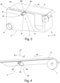
figure 3 shows an axonometric view of the improved machine, object of the present invention, in a second embodiment; -
figure 4 shows a second axonometric view of a detail of the improved machine shown infigure 3 ; and -
figure 5 shows a further axonometric view of the detail shown infigure 4 . - In the various figures, the similar parts will be indicated with the same numerical references.
- Referring to the attached figures, a machine M for working workpieces made of wood, ceramic, plastic, metal, glass, fiberglass and the like according to the present invention can be seen.
- In particular, said machine M mainly comprises a
tool 1, advancing means (not shown in the figures), for advancing the workpiece P to be machined, a blowingdevice 2, and anenclosure 3. - The advancing means, as said, allow the advancement of the workpiece P to be machined according to an advancement direction W, parallel to an advancement axis X.
- The
tool 1 is arranged on a plane parallel to a perpendicular plane XY, identified, in its turn, by said advancement axis X and from an axis Y, the latter perpendicular to the surface of said workpiece P. - The blowing
device 2 is arranged downstream of saidtool 1, with respect to said advancement direction W. - The
enclosure 3 encloses saidtool 1 and said blowingdevice 2. - Said workpiece P to be machined can be, for example, a panel, as shown in the figures.
- Said
tool 1 is of the rotary type, such as for example a blade or a cutter, and is able to rotate around an axis parallel to a horizontal axis Z, perpendicular to said perpendicular plane XY. - The
tool 1 is also able to translate along an axis parallel to said axis Y, and along an axis parallel to said horizontal axis Z. - Said
tool 1 can rotate around an axis parallel to said advancement axis X, so as to tilt with respect to said workpiece P. - Said
tool 1 is able to perform machining, such as grooves or incisions, on the surface of said workpiece P. In particular, in the case at issue, saidtool 1 is capable of rotating around said horizontal axis Z in favor of the advancement of said piece P, i.e. in such a way that its peripheral speed in proximity to said workpiece P is integral with said advancement direction W. - During the execution of the machining operations on said workpiece P, said
tool 1 generates a chip jet having an expulsion speed, which is concordant with said advancement direction W. - The blowing
device 2 generates an airflow to reduce the expulsion speed of said chip jet. In particular, said blowingdevice 2 is arranged inside saidenclosure 3 at the maximum distance allowed by saidtool 1. The air flow of the blowingdevice 2 allows a drastic reduction in the expulsion speed of the chips, so as to cause them to fall in theenclosure 3. - Referring in particular to the first embodiment shown in
figures 1-2 , said blowingdevice 2 comprises at least onenozzle 21, capable of directing said airflow. - Said blowing
device 2 also comprises movingmeans 22, capable of moving saidnozzle 21 along an axis parallel to said horizontal axis Z, to better intercept the chip jet. - Said
enclosure 3 comprises suction means, not shown in the figure, capable of sucking the chip, and asuction duct 31, connected to said suction means, capable of conveying the chip generated by the machining of said piece P towards said suction means. - The operation of the machine M described above is as follows.
- When it is intended to perform a machining on said workpiece P made of wood, ceramic, plastic, metal, glass, fiberglass, and the like, such as for example a groove or an incision, said workpiece P is positioned upstream of said
tool 1 with respect to said advancement direction W, so that the surface to be machined is parallel to a horizontal plane XZ, identified by said advancement axis and said horizontal Z axis. - Said workpiece P is then moved by said advancement means, along the advancement axis X in said advancement direction W.
- The
tool 1 translates along an axis parallel to the Y axis and along an axis parallel to the horizontal Z axis, so as to reach the appropriate height to carry out the desired machining. - Said
tool 1 therefore rotates in favor of the advancement of said workpiece P. - Said moving means 22 moves said
nozzle 21 along an axis parallel to said horizontal axis Z, so as to align it with saidtool 1 with respect to said advancement X axis. - Said
nozzle 21 directs said air flow generated by said blowingdevice 2 towards said groove or incision on said workpiece P. - When said piece P, advancing according to said advancement direction W, reaches said
tool 1, saidtool 1 performs the predetermined machining on said workpiece P, while said workpiece P continues to advance along said advancement direction W. - During machining, said
tool 1 generates a jet of chips at high speed along said direction of advance W. - Said jet of chip advances until it reaches said blowing
device 2. - The airflow generated by said
nozzle 21 decreases the speed of said chip jet, which falls into theenclosure 3, and it is sucked through saidsuction duct 31, which conveys it towards said suction means. - Said workpiece P then continues to advance along said advancement direction until it exits from said machine M.
- Referring now to
figures 3-5 , it is possible to observe a machine for machining pieces M, equipped with a second embodiment of saidblowing device 2. - In this case, the
blowing device 2 comprises arotating selector 23, as better described below, which is able to rotate to direct said airflow. - More specifically, the rotating
selector 23 of theblowing device 2 comprises afirst cylinder 24 and asecond cylinder 25. - The moving means 22 of the
blowing device 2 are capable of allowing the rotation of saidrotating selector 23. - Said
first cylinder 24 is arranged along a direction parallel to said horizontal axis Z. - Furthermore, said
first cylinder 24 is hollow and has alongitudinal slot 241, on the lateral surface, directed towards the workpiece P, and in particular towards said groove or incision. In particular, in the present embodiment, thelongitudinal slot 241 is parallel to said horizontal axis Z and oriented upwards, i.e. towards the workpiece P. - In other embodiments, said
first cylinder 24 can be arranged along different axes, also inclined with respect to the workpiece (i.e., with respect to said Z axis). - Said
longitudinal slot 241 passes through, thus putting the interior of said firsthollow cylinder 24 in communication with the exterior. - Said
second cylinder 25 is arranged inside saidfirst cylinder 24 and rotatably mounted with respect to it. In particular, the external surface of saidsecond cylinder 25 is in contact with the internal surface of saidfirst cylinder 24. - Said
second cylinder 25 is also hollow and has a plurality ofopenings 251, 252 (in the figure only two are shown), arranged along a spiral on its external surface of saidsecond cylinder 25. Saidopenings second cylinder 25 in fluid-dynamic communication with the exterior. - Said
second cylinder 25 is capable of containing compressed air inside and to make it exit through saidopenings - Each
opening longitudinal slot 241 of saidfirst cylinder 24 at a specific angle of rotation of saidsecond cylinder 25. This allows selecting the portion of saidlongitudinal slot 241 from which making said flow airflow to come out. - The operation of said machine M equipped with said
blowing device 2 according to the second embodiment is in general terms similar to that of machine M shown infigures 1 and 2 . However, when it is necessary to move the direction of the airflow, said rotatingselector 23 is moved by said movingmeans 22, to align said airflow with saidtool 1 with respect to said advancement axis X. - In particular, said
second cylinder 25 rotates inside saidfirst cylinder 24, so to align the appropriate opening of said plurality of openings with saidlongitudinal slot 241 of saidfirst cylinder 24. - Said air flow then exits from said
second cylinder 25, through the opening aligned with saidlongitudinal slot 241. - In a further form of embodiment of the
blowing device 2, not shown in the figures, saidfirst cylinder 24 is hollow and has a plurality of openings, arranged along a spiral on its external surface, which put the interior of saidsecond cylinder 24 in fluid-dynamic communication with the exterior. - Said
second cylinder 25 is arranged inside saidfirst cylinder 24. - In particular, the external surface of said
second cylinder 25 is in contact with the internal surface of saidfirst cylinder 24 and saidfirst cylinder 24 is rotatably mounted with respect to saidsecond cylinder 25. - Said
second cylinder 25 is also hollow and has a longitudinal slot, on the lateral surface, directed towards the workpiece P, and in particular towards said groove or incision. - Said
second cylinder 25 is capable of containing compressed air inside and making it come out through said longitudinal slot. - Said longitudinal slot is parallel to said horizontal axis Z, and oriented upwards, or, in the embodiment at issue, towards the workpiece P.
- Said longitudinal slot is passing through, thus putting the interior of said
second cylinder 25 into fluid-dynamic communication with the outside. - Each opening of said
first cylinder 24 is capable of aligning itself with said longitudinal slot of saidsecond cylinder 25 at a specific angle of rotation of saidfirst cylinder 24. - The operation of said
blowing device 2 according to the third embodiment is completely similar to that of the blower according to the second embodiment, except that saidsecond cylinder 25 does not rotate with respect to said workpiece P, while saidfirst cylinder 24 rotates with respect to saidsecond cylinder 25, to select the opening of saidfirst cylinder 24 and the corresponding portion of said longitudinal slot of saidsecond cylinder 25, from which to let said air flow out. - Said machine M according to the invention can be an edge banding machine for wooden panels, used for finishing the surface machining of such panels by applying a decorative edge. The decorative edges are usually plastic, wooden or metal edging tapes, supplied in the form of reels.
- This edge-banding machine, in addition to the machining unit described above, which realizes the groove, comprises, downstream or upstream of said tool U, an edge banding station arranged in correspondence with one side of the support surface of the workpiece P, equipped with advancement means, along the advancement axis X in said advancement direction W.
- The edge-banding station comprises, in turn, a coating unit, for applying the glue on said lateral surface to be coated while said workpiece P, such as for example a panel, slides, a reel of edge-banding tape and a pressure unit comprising pressure rollers, arranged downstream of the spreading unit, to make the edge-banding tape adhere to said glued side surface.
- Such edge-banding machines of the prior art also comprise cutters, arranged downstream of the beading station, for cutting and rounding the excesses of the previously applied edge-banding tape.
- A clear advantage of the present invention is the possibility of having a machine for machining workpieces made of wood, ceramic, plastic, metal, glass, fiberglass, and the like, which allows containing and sucking the chip resulting from machining in an optimal way.
- The present invention has been described for illustrative but not limitative purposes, according to its preferred embodiments, but it is to be understood that modifications and/or changes can be introduced by those skilled in the art without departing from the relevant scope as defined in the enclosed claims.
Claims (11)
- Machine (M) for machining workpieces (P) made of wood, ceramic, plastic, metal, glass, fiberglass and the like, comprisingat least one tool (1), capable of performing machining on the surface of said workpiece (P), in such a way to create a jet of chips essentially oriented along an expulsion direction having an expulsion speed,wherein said machine (M) is characterized in that it comprises a blowing device (2), placed after said tool (1) with respect to said expulsion direction, capable of generating an air flow to reduce the expulsion speed of said jet of chips.
- Machine (M) according to the previous claim, characterizedin that it comprises advancing means, to allow the advancement of said workpieces (P) to be machined along an advancement direction (W), parallel to an advancement axis (X), andin that said advancement direction (W) is synchronous with said expulsion direction.
- Machine (M) according to any one of the previous claims, characterized in that said tool is a blade (1).
- Machine (M) according to any one of claims 2 or 3, characterized in that said tool (1) is capable of rotating with said advancement direction (W) of said workpiece (P) around an axis parallel to a horizontal axis (Z), perpendicular to said perpendicular plane (XY), and it is capable of translating along an axis parallel to said axis (Y) and along an axis parallel to said horizontal axis (Z).
- Machine (M) according to any one of the previous claims, characterized in that said blowing device (2) comprisesat least one nozzle (21) from which said air flow comes out, andmoving means (22), capable of moving said nozzle (21) in such a way to intercept said jet of chips.
- Machine (M) according to any one of claims 1 - 4, characterized in that said blowing device (2) comprisesa rotating selector (23), capable of letting out said air flow in such a way to intercept said jet of chips, andmoving means (22), capable of allowing the rotation of said rotating selector (23).
- Machine (M) according to the previous claim, characterized in that said rotating selector (23) comprisesa hollow first cylinder (24), having a longitudinal through eyelet (241), on its lateral surface, oriented towards the workpiece (P); anda hollow second cylinder (25), placed inside said first cylinder (24) and free to rotate with respect to said first cylinder (24), through which compressed air can flow, and comprising a plurality of openings (251, 252), placed along its external surface, capable of creating a fluidic connection between the inside of said second cylinder (25) and the outside, such that, when said second cylinder (25) rotates with respect to said first cylinder (24), a portion of said longitudinal eyelet (241) is selected to let through said air flow passing through the opening (251, 252) placed by said longitudinal eyelet (241).
- Machine (M) according to claim 6, characterized in that said rotating selector (23) comprisesa hollow second cylinder (25), having a longitudinal through eyelet, on its lateral surface, oriented towards the workpiece (P); anda hollow first cylinder (24), placed outside said second cylinder (25) and free to rotate with respect to said second cylinder (25), comprising a plurality of openings, placed along its external surface, capable of creating a fluidic connection between the inside of said first cylinder (24) and the outside, such that, when said first cylinder (24) rotates with respect to said second cylinder (25), a portion of said longitudinal eyelet is selected to let through said air flow passing through the opening placed by said longitudinal eyelet.
- Machine (M) according to any one of the previous claims, characterizedin that it comprises an enclosure (3) andin that said tool (1) and said blowing device (2) are housed within said enclosure (3).
- Machine (M) according to the previous claim, characterized in that said enclosure (3) comprises
suction means, capable of sucking said chips, anda suction duct (31), connected to said suction means, capable of directing said chips towards said suction means, andin that said blowing device (2) is capable of generating an air flow to direct said chips towards said suction duct (31). - Machine (M) according to any one of the previous claims, characterized in that it comprises an edge bander group placed before or after said tool (1).
Applications Claiming Priority (1)
| Application Number | Priority Date | Filing Date | Title |
|---|---|---|---|
| IT102021000021473A IT202100021473A1 (en) | 2021-08-06 | 2021-08-06 | MACHINE FOR PROCESSING PIECES |
Publications (2)
| Publication Number | Publication Date |
|---|---|
| EP4129567A1 true EP4129567A1 (en) | 2023-02-08 |
| EP4129567B1 EP4129567B1 (en) | 2026-03-04 |
Family
ID=78536496
Family Applications (1)
| Application Number | Title | Priority Date | Filing Date |
|---|---|---|---|
| EP22187144.5A Active EP4129567B1 (en) | 2021-08-06 | 2022-07-27 | Machine for machining workpieces, with a blowing device |
Country Status (2)
| Country | Link |
|---|---|
| EP (1) | EP4129567B1 (en) |
| IT (1) | IT202100021473A1 (en) |
Citations (4)
| Publication number | Priority date | Publication date | Assignee | Title |
|---|---|---|---|---|
| DE7138005U (en) * | 1971-10-07 | 1972-04-13 | Bank A | Additional device, in particular jigsaw attachment for hand drills |
| DE3800050A1 (en) * | 1987-01-05 | 1988-07-14 | Aciera S A | Extraction method for pulverulent machining waste |
| DE102007023664A1 (en) * | 2007-05-12 | 2008-11-13 | Holzma Plattenaufteiltechnik Gmbh | Plate dividing device for large sized plate, has sawing device movable along sectional gap on supporting table in sawing direction, where nozzle is connected with gas source, and/or cut section lying above gap |
| DE102016209107A1 (en) * | 2016-05-25 | 2017-11-30 | Homag Gmbh | A barrier fluid device for a processing apparatus, processing apparatus, and method for producing a barrier fluid |
-
2021
- 2021-08-06 IT IT102021000021473A patent/IT202100021473A1/en unknown
-
2022
- 2022-07-27 EP EP22187144.5A patent/EP4129567B1/en active Active
Patent Citations (4)
| Publication number | Priority date | Publication date | Assignee | Title |
|---|---|---|---|---|
| DE7138005U (en) * | 1971-10-07 | 1972-04-13 | Bank A | Additional device, in particular jigsaw attachment for hand drills |
| DE3800050A1 (en) * | 1987-01-05 | 1988-07-14 | Aciera S A | Extraction method for pulverulent machining waste |
| DE102007023664A1 (en) * | 2007-05-12 | 2008-11-13 | Holzma Plattenaufteiltechnik Gmbh | Plate dividing device for large sized plate, has sawing device movable along sectional gap on supporting table in sawing direction, where nozzle is connected with gas source, and/or cut section lying above gap |
| DE102016209107A1 (en) * | 2016-05-25 | 2017-11-30 | Homag Gmbh | A barrier fluid device for a processing apparatus, processing apparatus, and method for producing a barrier fluid |
Also Published As
| Publication number | Publication date |
|---|---|
| IT202100021473A1 (en) | 2023-02-06 |
| EP4129567B1 (en) | 2026-03-04 |
Similar Documents
| Publication | Publication Date | Title |
|---|---|---|
| JP3877128B2 (en) | Fine groove processing machine for pads for semiconductor CMP processing | |
| US5605492A (en) | Method and machine tool for cutting workpieces | |
| US6710294B2 (en) | Debris removal apparatus for use in laser ablation | |
| US4720243A (en) | Impeller of centrifugal fluid-type rotary machine | |
| ITBO930422A1 (en) | UNIT FOR THE PROCESSING OF WOOD PIECES. | |
| US4853058A (en) | Apparatus and method for adhering tape to nonstraight workpiece edge | |
| US6390900B1 (en) | Finishing tool for CNC router machines | |
| US6626617B2 (en) | Process for the milling of a groove into a board-like workpiece as well as processing machine for carrying out the process | |
| EP4129567B1 (en) | Machine for machining workpieces, with a blowing device | |
| CN104708678A (en) | Device and method for machining workpieces | |
| JP2018030202A (en) | Processing apparatus and processing method | |
| EP3941698A1 (en) | A method of machining longitudinal wood-like components and a workstand to perform thereof | |
| US3209800A (en) | Machine for edge trimming | |
| EP3552786A1 (en) | Machine and method for machining an edge of a workpiece | |
| JP4009237B2 (en) | Fine groove processing machine for pads for semiconductor CMP processing | |
| EP3566840B1 (en) | Operating head for machines for the processing of components made of wood or the like | |
| KR102173888B1 (en) | Wood processing apparatus capable of sequential cutting and grinding | |
| CN110014192A (en) | Band sawing machine | |
| EP1588812B1 (en) | An edge banding machine with laser cutting system | |
| CN209441088U (en) | A kind of wood carving machine with cleaning device | |
| IT202100031121A1 (en) | Machine with improved extraction unit and improved extraction hood | |
| EP3915726A1 (en) | Machine for working wooden workpieces comprising a laser system and operation method thereof | |
| JP7013121B2 (en) | Air-cooled spindle exhaust redirection system to improve the recovery of machined by-products | |
| CN206914015U (en) | Full-automatic cutting engraving machine | |
| IT201800006497A1 (en) | MILLING DEVICE FOR EDGE BANDING MACHINE |
Legal Events
| Date | Code | Title | Description |
|---|---|---|---|
| PUAI | Public reference made under article 153(3) epc to a published international application that has entered the european phase |
Free format text: ORIGINAL CODE: 0009012 |
|
| STAA | Information on the status of an ep patent application or granted ep patent |
Free format text: STATUS: THE APPLICATION HAS BEEN PUBLISHED |
|
| AK | Designated contracting states |
Kind code of ref document: A1 Designated state(s): AL AT BE BG CH CY CZ DE DK EE ES FI FR GB GR HR HU IE IS IT LI LT LU LV MC MK MT NL NO PL PT RO RS SE SI SK SM TR |
|
| P01 | Opt-out of the competence of the unified patent court (upc) registered |
Effective date: 20230519 |
|
| STAA | Information on the status of an ep patent application or granted ep patent |
Free format text: STATUS: REQUEST FOR EXAMINATION WAS MADE |
|
| 17P | Request for examination filed |
Effective date: 20230807 |
|
| RBV | Designated contracting states (corrected) |
Designated state(s): AL AT BE BG CH CY CZ DE DK EE ES FI FR GB GR HR HU IE IS IT LI LT LU LV MC MK MT NL NO PL PT RO RS SE SI SK SM TR |
|
| GRAP | Despatch of communication of intention to grant a patent |
Free format text: ORIGINAL CODE: EPIDOSNIGR1 |
|
| STAA | Information on the status of an ep patent application or granted ep patent |
Free format text: STATUS: GRANT OF PATENT IS INTENDED |
|
| RIC1 | Information provided on ipc code assigned before grant |
Ipc: B23Q 11/00 20060101AFI20250926BHEP Ipc: B23D 59/00 20060101ALI20250926BHEP |
|
| INTG | Intention to grant announced |
Effective date: 20251010 |
|
| GRAS | Grant fee paid |
Free format text: ORIGINAL CODE: EPIDOSNIGR3 |
|
| GRAA | (expected) grant |
Free format text: ORIGINAL CODE: 0009210 |
|
| STAA | Information on the status of an ep patent application or granted ep patent |
Free format text: STATUS: THE PATENT HAS BEEN GRANTED |
|
| AK | Designated contracting states |
Kind code of ref document: B1 Designated state(s): AL AT BE BG CH CY CZ DE DK EE ES FI FR GB GR HR HU IE IS IT LI LT LU LV MC MK MT NL NO PL PT RO RS SE SI SK SM TR |
|
| REG | Reference to a national code |
Ref country code: CH Ref legal event code: F10 Free format text: ST27 STATUS EVENT CODE: U-0-0-F10-F00 (AS PROVIDED BY THE NATIONAL OFFICE) Effective date: 20260304 Ref country code: GB Ref legal event code: FG4D |
|
| REG | Reference to a national code |
Ref country code: DE Ref legal event code: R096 Ref document number: 602022031487 Country of ref document: DE |
|
| REG | Reference to a national code |
Ref country code: IE Ref legal event code: FG4D |