EP4129456A1 - Separation film - Google Patents
Separation film Download PDFInfo
- Publication number
- EP4129456A1 EP4129456A1 EP21776506.4A EP21776506A EP4129456A1 EP 4129456 A1 EP4129456 A1 EP 4129456A1 EP 21776506 A EP21776506 A EP 21776506A EP 4129456 A1 EP4129456 A1 EP 4129456A1
- Authority
- EP
- European Patent Office
- Prior art keywords
- separation membrane
- separation
- group
- functional layer
- interlayer
- Prior art date
- Legal status (The legal status is an assumption and is not a legal conclusion. Google has not performed a legal analysis and makes no representation as to the accuracy of the status listed.)
- Withdrawn
Links
- 238000000926 separation method Methods 0.000 title claims abstract description 243
- 239000012528 membrane Substances 0.000 claims abstract description 142
- 239000002346 layers by function Substances 0.000 claims abstract description 88
- 239000011229 interlayer Substances 0.000 claims abstract description 68
- 229920000642 polymer Polymers 0.000 claims abstract description 39
- 150000001875 compounds Chemical class 0.000 claims abstract description 38
- 230000004907 flux Effects 0.000 claims abstract description 22
- 239000007788 liquid Substances 0.000 claims description 96
- LFQSCWFLJHTTHZ-UHFFFAOYSA-N Ethanol Chemical compound CCO LFQSCWFLJHTTHZ-UHFFFAOYSA-N 0.000 claims description 95
- XLYOFNOQVPJJNP-UHFFFAOYSA-N water Substances O XLYOFNOQVPJJNP-UHFFFAOYSA-N 0.000 claims description 86
- 239000000203 mixture Substances 0.000 claims description 61
- 239000000945 filler Substances 0.000 claims description 52
- 238000000034 method Methods 0.000 claims description 39
- 125000001183 hydrocarbyl group Chemical group 0.000 claims description 37
- 239000004642 Polyimide Substances 0.000 claims description 31
- 229920001721 polyimide Polymers 0.000 claims description 31
- 125000004432 carbon atom Chemical group C* 0.000 claims description 27
- 125000005647 linker group Chemical group 0.000 claims description 22
- 229920002614 Polyether block amide Polymers 0.000 claims description 19
- 125000003118 aryl group Chemical group 0.000 claims description 19
- 125000003545 alkoxy group Chemical group 0.000 claims description 18
- 239000011159 matrix material Substances 0.000 claims description 16
- 125000004435 hydrogen atom Chemical group [H]* 0.000 claims description 14
- 125000005843 halogen group Chemical group 0.000 claims description 11
- 125000002887 hydroxy group Chemical group [H]O* 0.000 claims description 11
- 238000005259 measurement Methods 0.000 claims description 11
- 125000001424 substituent group Chemical group 0.000 claims description 11
- 239000004721 Polyphenylene oxide Substances 0.000 claims description 7
- 239000004372 Polyvinyl alcohol Substances 0.000 claims description 5
- 229920000570 polyether Polymers 0.000 claims description 5
- 229920002451 polyvinyl alcohol Polymers 0.000 claims description 5
- 125000000843 phenylene group Chemical group C1(=C(C=CC=C1)*)* 0.000 claims description 4
- 239000004814 polyurethane Substances 0.000 claims description 4
- 229920002635 polyurethane Polymers 0.000 claims description 4
- 239000012530 fluid Substances 0.000 abstract description 26
- 230000007547 defect Effects 0.000 abstract description 25
- 230000003247 decreasing effect Effects 0.000 abstract description 6
- 239000011248 coating agent Substances 0.000 description 47
- 238000000576 coating method Methods 0.000 description 47
- -1 propane-2,2-diyl group Chemical group 0.000 description 34
- 238000001179 sorption measurement Methods 0.000 description 25
- KFZMGEQAYNKOFK-UHFFFAOYSA-N Isopropanol Chemical compound CC(C)O KFZMGEQAYNKOFK-UHFFFAOYSA-N 0.000 description 15
- 125000004429 atom Chemical group 0.000 description 15
- SECXISVLQFMRJM-UHFFFAOYSA-N N-Methylpyrrolidone Chemical compound CN1CCCC1=O SECXISVLQFMRJM-UHFFFAOYSA-N 0.000 description 12
- GTDPSWPPOUPBNX-UHFFFAOYSA-N ac1mqpva Chemical compound CC12C(=O)OC(=O)C1(C)C1(C)C2(C)C(=O)OC1=O GTDPSWPPOUPBNX-UHFFFAOYSA-N 0.000 description 12
- 125000006158 tetracarboxylic acid group Chemical group 0.000 description 12
- 239000000463 material Substances 0.000 description 11
- 239000002245 particle Substances 0.000 description 10
- 239000004952 Polyamide Substances 0.000 description 9
- 125000002947 alkylene group Chemical group 0.000 description 9
- 229910052751 metal Inorganic materials 0.000 description 9
- 239000002184 metal Substances 0.000 description 9
- 229920002647 polyamide Polymers 0.000 description 9
- 239000002253 acid Substances 0.000 description 8
- 239000012621 metal-organic framework Substances 0.000 description 8
- 239000002904 solvent Substances 0.000 description 8
- 229910052757 nitrogen Inorganic materials 0.000 description 7
- 125000004430 oxygen atom Chemical group O* 0.000 description 7
- 125000001140 1,4-phenylene group Chemical group [H]C1=C([H])C([*:2])=C([H])C([H])=C1[*:1] 0.000 description 6
- WFDIJRYMOXRFFG-UHFFFAOYSA-N Acetic anhydride Chemical compound CC(=O)OC(C)=O WFDIJRYMOXRFFG-UHFFFAOYSA-N 0.000 description 6
- ZMANZCXQSJIPKH-UHFFFAOYSA-N Triethylamine Chemical compound CCN(CC)CC ZMANZCXQSJIPKH-UHFFFAOYSA-N 0.000 description 6
- 125000004433 nitrogen atom Chemical group N* 0.000 description 6
- 229920005989 resin Polymers 0.000 description 6
- 239000011347 resin Substances 0.000 description 6
- 239000000126 substance Substances 0.000 description 6
- 239000002033 PVDF binder Substances 0.000 description 5
- 238000004040 coloring Methods 0.000 description 5
- 125000000524 functional group Chemical group 0.000 description 5
- 150000002500 ions Chemical class 0.000 description 5
- 239000010410 layer Substances 0.000 description 5
- 239000013110 organic ligand Substances 0.000 description 5
- 229920002981 polyvinylidene fluoride Polymers 0.000 description 5
- WNXJIVFYUVYPPR-UHFFFAOYSA-N 1,3-dioxolane Chemical compound C1COCO1 WNXJIVFYUVYPPR-UHFFFAOYSA-N 0.000 description 4
- IJGRMHOSHXDMSA-UHFFFAOYSA-N Atomic nitrogen Chemical compound N#N IJGRMHOSHXDMSA-UHFFFAOYSA-N 0.000 description 4
- 125000003178 carboxy group Chemical group [H]OC(*)=O 0.000 description 4
- 239000006185 dispersion Substances 0.000 description 4
- 125000001033 ether group Chemical group 0.000 description 4
- 239000007789 gas Substances 0.000 description 4
- 230000002401 inhibitory effect Effects 0.000 description 4
- 238000005373 pervaporation Methods 0.000 description 4
- 125000005543 phthalimide group Chemical group 0.000 description 4
- 229920005573 silicon-containing polymer Polymers 0.000 description 4
- KKTUQAYCCLMNOA-UHFFFAOYSA-N 2,3-diaminobenzoic acid Chemical compound NC1=CC=CC(C(O)=O)=C1N KKTUQAYCCLMNOA-UHFFFAOYSA-N 0.000 description 3
- UENRXLSRMCSUSN-UHFFFAOYSA-N 3,5-diaminobenzoic acid Chemical compound NC1=CC(N)=CC(C(O)=O)=C1 UENRXLSRMCSUSN-UHFFFAOYSA-N 0.000 description 3
- 239000002202 Polyethylene glycol Substances 0.000 description 3
- JUJWROOIHBZHMG-UHFFFAOYSA-N Pyridine Chemical group C1=CC=NC=C1 JUJWROOIHBZHMG-UHFFFAOYSA-N 0.000 description 3
- 125000003368 amide group Chemical group 0.000 description 3
- 238000009835 boiling Methods 0.000 description 3
- 125000004185 ester group Chemical group 0.000 description 3
- 239000001257 hydrogen Substances 0.000 description 3
- 229910052739 hydrogen Inorganic materials 0.000 description 3
- 238000004519 manufacturing process Methods 0.000 description 3
- 239000002808 molecular sieve Substances 0.000 description 3
- 125000000449 nitro group Chemical group [O-][N+](*)=O 0.000 description 3
- 239000004745 nonwoven fabric Substances 0.000 description 3
- 125000001997 phenyl group Chemical group [H]C1=C([H])C([H])=C(*)C([H])=C1[H] 0.000 description 3
- 229920001223 polyethylene glycol Polymers 0.000 description 3
- URGAHOPLAPQHLN-UHFFFAOYSA-N sodium aluminosilicate Chemical compound [Na+].[Al+3].[O-][Si]([O-])=O.[O-][Si]([O-])=O URGAHOPLAPQHLN-UHFFFAOYSA-N 0.000 description 3
- 229910052717 sulfur Inorganic materials 0.000 description 3
- 125000004434 sulfur atom Chemical group 0.000 description 3
- 125000002030 1,2-phenylene group Chemical group [H]C1=C([H])C([*:1])=C([*:2])C([H])=C1[H] 0.000 description 2
- OYFRNYNHAZOYNF-UHFFFAOYSA-N 2,5-dihydroxyterephthalic acid Chemical compound OC(=O)C1=CC(O)=C(C(O)=O)C=C1O OYFRNYNHAZOYNF-UHFFFAOYSA-N 0.000 description 2
- CDOWNLMZVKJRSC-UHFFFAOYSA-N 2-hydroxyterephthalic acid Chemical compound OC(=O)C1=CC=C(C(O)=O)C(O)=C1 CDOWNLMZVKJRSC-UHFFFAOYSA-N 0.000 description 2
- 229920001780 ECTFE Polymers 0.000 description 2
- 239000013118 MOF-74-type framework Substances 0.000 description 2
- YAGCJGCCZIARMJ-UHFFFAOYSA-N N1C(=NC=C1)C=O.[Zn] Chemical compound N1C(=NC=C1)C=O.[Zn] YAGCJGCCZIARMJ-UHFFFAOYSA-N 0.000 description 2
- 239000004698 Polyethylene Substances 0.000 description 2
- 239000004734 Polyphenylene sulfide Substances 0.000 description 2
- VYPSYNLAJGMNEJ-UHFFFAOYSA-N Silicium dioxide Chemical compound O=[Si]=O VYPSYNLAJGMNEJ-UHFFFAOYSA-N 0.000 description 2
- XUIMIQQOPSSXEZ-UHFFFAOYSA-N Silicon Chemical group [Si] XUIMIQQOPSSXEZ-UHFFFAOYSA-N 0.000 description 2
- KKEYFWRCBNTPAC-UHFFFAOYSA-N Terephthalic acid Chemical compound OC(=O)C1=CC=C(C(O)=O)C=C1 KKEYFWRCBNTPAC-UHFFFAOYSA-N 0.000 description 2
- 229910021536 Zeolite Inorganic materials 0.000 description 2
- 229920000122 acrylonitrile butadiene styrene Polymers 0.000 description 2
- 239000003795 chemical substances by application Substances 0.000 description 2
- 238000009833 condensation Methods 0.000 description 2
- 230000005494 condensation Effects 0.000 description 2
- 238000005520 cutting process Methods 0.000 description 2
- 230000018044 dehydration Effects 0.000 description 2
- 238000006297 dehydration reaction Methods 0.000 description 2
- 229910001873 dinitrogen Inorganic materials 0.000 description 2
- HNPSIPDUKPIQMN-UHFFFAOYSA-N dioxosilane;oxo(oxoalumanyloxy)alumane Chemical compound O=[Si]=O.O=[Al]O[Al]=O HNPSIPDUKPIQMN-UHFFFAOYSA-N 0.000 description 2
- 125000000816 ethylene group Chemical group [H]C([H])([*:1])C([H])([H])[*:2] 0.000 description 2
- 238000010438 heat treatment Methods 0.000 description 2
- 125000000468 ketone group Chemical group 0.000 description 2
- 229910021645 metal ion Inorganic materials 0.000 description 2
- 238000001000 micrograph Methods 0.000 description 2
- 230000004048 modification Effects 0.000 description 2
- 238000012986 modification Methods 0.000 description 2
- 239000003960 organic solvent Substances 0.000 description 2
- 239000012466 permeate Substances 0.000 description 2
- 239000003495 polar organic solvent Substances 0.000 description 2
- 229920002492 poly(sulfone) Polymers 0.000 description 2
- 229920001955 polyphenylene ether Polymers 0.000 description 2
- 229920000069 polyphenylene sulfide Polymers 0.000 description 2
- 229920001296 polysiloxane Polymers 0.000 description 2
- 239000013259 porous coordination polymer Substances 0.000 description 2
- 239000011148 porous material Substances 0.000 description 2
- 229910052710 silicon Inorganic materials 0.000 description 2
- 125000000472 sulfonyl group Chemical group *S(*)(=O)=O 0.000 description 2
- 125000000383 tetramethylene group Chemical group [H]C([H])([*:1])C([H])([H])C([H])([H])C([H])([H])[*:2] 0.000 description 2
- 125000000101 thioether group Chemical group 0.000 description 2
- 238000000108 ultra-filtration Methods 0.000 description 2
- 239000010457 zeolite Substances 0.000 description 2
- GEYOCULIXLDCMW-UHFFFAOYSA-N 1,2-phenylenediamine Chemical compound NC1=CC=CC=C1N GEYOCULIXLDCMW-UHFFFAOYSA-N 0.000 description 1
- CNCGBKWWMNGKIG-UHFFFAOYSA-N 1,3-dioxo-2-benzofuran-5-carboxylic acid ethene Chemical group C=C.O=C1OC(C2=CC(=CC=C12)C(=O)O)=O.O=C1OC(C2=CC(=CC=C12)C(=O)O)=O CNCGBKWWMNGKIG-UHFFFAOYSA-N 0.000 description 1
- 125000001989 1,3-phenylene group Chemical group [H]C1=C([H])C([*:1])=C([H])C([*:2])=C1[H] 0.000 description 1
- VLDPXPPHXDGHEW-UHFFFAOYSA-N 1-chloro-2-dichlorophosphoryloxybenzene Chemical compound ClC1=CC=CC=C1OP(Cl)(Cl)=O VLDPXPPHXDGHEW-UHFFFAOYSA-N 0.000 description 1
- ZOMATQMEHRJKLO-UHFFFAOYSA-N 1h-imidazol-2-ylmethanol Chemical compound OCC1=NC=CN1 ZOMATQMEHRJKLO-UHFFFAOYSA-N 0.000 description 1
- XYHKNCXZYYTLRG-UHFFFAOYSA-N 1h-imidazole-2-carbaldehyde Chemical compound O=CC1=NC=CN1 XYHKNCXZYYTLRG-UHFFFAOYSA-N 0.000 description 1
- GPNNOCMCNFXRAO-UHFFFAOYSA-N 2-aminoterephthalic acid Chemical compound NC1=CC(C(O)=O)=CC=C1C(O)=O GPNNOCMCNFXRAO-UHFFFAOYSA-N 0.000 description 1
- HLBLWEWZXPIGSM-UHFFFAOYSA-N 4-Aminophenyl ether Chemical compound C1=CC(N)=CC=C1OC1=CC=C(N)C=C1 HLBLWEWZXPIGSM-UHFFFAOYSA-N 0.000 description 1
- QHHKLPCQTTWFSS-UHFFFAOYSA-N 5-[2-(1,3-dioxo-2-benzofuran-5-yl)-1,1,1,3,3,3-hexafluoropropan-2-yl]-2-benzofuran-1,3-dione Chemical compound C1=C2C(=O)OC(=O)C2=CC(C(C=2C=C3C(=O)OC(=O)C3=CC=2)(C(F)(F)F)C(F)(F)F)=C1 QHHKLPCQTTWFSS-UHFFFAOYSA-N 0.000 description 1
- 239000013148 Cu-BTC MOF Substances 0.000 description 1
- YLQBMQCUIZJEEH-UHFFFAOYSA-N Furan Chemical group C=1C=COC=1 YLQBMQCUIZJEEH-UHFFFAOYSA-N 0.000 description 1
- 239000004677 Nylon Substances 0.000 description 1
- 239000004696 Poly ether ether ketone Substances 0.000 description 1
- 239000004743 Polypropylene Substances 0.000 description 1
- YTPLMLYBLZKORZ-UHFFFAOYSA-N Thiophene Chemical group C=1C=CSC=1 YTPLMLYBLZKORZ-UHFFFAOYSA-N 0.000 description 1
- RTAQQCXQSZGOHL-UHFFFAOYSA-N Titanium Chemical compound [Ti] RTAQQCXQSZGOHL-UHFFFAOYSA-N 0.000 description 1
- 239000013207 UiO-66 Substances 0.000 description 1
- XECAHXYUAAWDEL-UHFFFAOYSA-N acrylonitrile butadiene styrene Chemical compound C=CC=C.C=CC#N.C=CC1=CC=CC=C1 XECAHXYUAAWDEL-UHFFFAOYSA-N 0.000 description 1
- 239000004676 acrylonitrile butadiene styrene Substances 0.000 description 1
- 125000003172 aldehyde group Chemical group 0.000 description 1
- 125000003277 amino group Chemical group 0.000 description 1
- 125000005577 anthracene group Chemical group 0.000 description 1
- 239000004760 aramid Substances 0.000 description 1
- 229920003235 aromatic polyamide Polymers 0.000 description 1
- HFACYLZERDEVSX-UHFFFAOYSA-N benzidine Chemical group C1=CC(N)=CC=C1C1=CC=C(N)C=C1 HFACYLZERDEVSX-UHFFFAOYSA-N 0.000 description 1
- 230000005540 biological transmission Effects 0.000 description 1
- 229920001400 block copolymer Polymers 0.000 description 1
- 229910052799 carbon Inorganic materials 0.000 description 1
- 239000000919 ceramic Substances 0.000 description 1
- 238000006243 chemical reaction Methods 0.000 description 1
- 230000000052 comparative effect Effects 0.000 description 1
- 239000002131 composite material Substances 0.000 description 1
- 230000002542 deteriorative effect Effects 0.000 description 1
- 239000004205 dimethyl polysiloxane Substances 0.000 description 1
- 235000013870 dimethyl polysiloxane Nutrition 0.000 description 1
- ZZTCPWRAHWXWCH-UHFFFAOYSA-N diphenylmethanediamine Chemical compound C=1C=CC=CC=1C(N)(N)C1=CC=CC=C1 ZZTCPWRAHWXWCH-UHFFFAOYSA-N 0.000 description 1
- 230000000694 effects Effects 0.000 description 1
- 230000002708 enhancing effect Effects 0.000 description 1
- 125000001301 ethoxy group Chemical group [H]C([H])([H])C([H])([H])O* 0.000 description 1
- 125000001495 ethyl group Chemical group [H]C([H])([H])C([H])([H])* 0.000 description 1
- 238000001704 evaporation Methods 0.000 description 1
- 230000008020 evaporation Effects 0.000 description 1
- 239000000835 fiber Substances 0.000 description 1
- 239000006260 foam Substances 0.000 description 1
- 238000004817 gas chromatography Methods 0.000 description 1
- 125000001072 heteroaryl group Chemical group 0.000 description 1
- 125000005842 heteroatom Chemical group 0.000 description 1
- 125000002883 imidazolyl group Chemical group 0.000 description 1
- 239000004816 latex Substances 0.000 description 1
- 229920000126 latex Polymers 0.000 description 1
- 229910052749 magnesium Inorganic materials 0.000 description 1
- 229910001425 magnesium ion Inorganic materials 0.000 description 1
- 239000006262 metallic foam Substances 0.000 description 1
- VNWKTOKETHGBQD-UHFFFAOYSA-N methane Chemical class C VNWKTOKETHGBQD-UHFFFAOYSA-N 0.000 description 1
- 125000000956 methoxy group Chemical group [H]C([H])([H])O* 0.000 description 1
- 125000002496 methyl group Chemical group [H]C([H])([H])* 0.000 description 1
- 125000001570 methylene group Chemical group [H]C([H])([*:1])[*:2] 0.000 description 1
- 125000002950 monocyclic group Chemical group 0.000 description 1
- 125000001624 naphthyl group Chemical group 0.000 description 1
- 229910052759 nickel Inorganic materials 0.000 description 1
- 229920001778 nylon Polymers 0.000 description 1
- YNPNZTXNASCQKK-UHFFFAOYSA-N phenanthrene Chemical group C1=CC=C2C3=CC=CC=C3C=CC2=C1 YNPNZTXNASCQKK-UHFFFAOYSA-N 0.000 description 1
- 229920000435 poly(dimethylsiloxane) Polymers 0.000 description 1
- 229920002239 polyacrylonitrile Polymers 0.000 description 1
- 229920000515 polycarbonate Polymers 0.000 description 1
- 239000004417 polycarbonate Substances 0.000 description 1
- 125000003367 polycyclic group Chemical group 0.000 description 1
- 229920000728 polyester Polymers 0.000 description 1
- 229920002530 polyetherether ketone Polymers 0.000 description 1
- 229920000573 polyethylene Polymers 0.000 description 1
- 229920013636 polyphenyl ether polymer Polymers 0.000 description 1
- 229920006380 polyphenylene oxide Polymers 0.000 description 1
- 229920001155 polypropylene Polymers 0.000 description 1
- 229920001343 polytetrafluoroethylene Polymers 0.000 description 1
- 239000004810 polytetrafluoroethylene Substances 0.000 description 1
- 229920002620 polyvinyl fluoride Polymers 0.000 description 1
- 239000005373 porous glass Substances 0.000 description 1
- 125000002572 propoxy group Chemical group [*]OC([H])([H])C(C([H])([H])[H])([H])[H] 0.000 description 1
- 125000001436 propyl group Chemical group [H]C([*])([H])C([H])([H])C([H])([H])[H] 0.000 description 1
- UMJSCPRVCHMLSP-UHFFFAOYSA-N pyridine Natural products COC1=CC=CN=C1 UMJSCPRVCHMLSP-UHFFFAOYSA-N 0.000 description 1
- 125000000168 pyrrolyl group Chemical group 0.000 description 1
- 238000007670 refining Methods 0.000 description 1
- 239000000377 silicon dioxide Substances 0.000 description 1
- 229920002379 silicone rubber Polymers 0.000 description 1
- 239000004945 silicone rubber Substances 0.000 description 1
- 239000007787 solid Substances 0.000 description 1
- 229910001220 stainless steel Inorganic materials 0.000 description 1
- 239000010935 stainless steel Substances 0.000 description 1
- 238000006467 substitution reaction Methods 0.000 description 1
- 230000008961 swelling Effects 0.000 description 1
- 239000010936 titanium Substances 0.000 description 1
- 229910052719 titanium Inorganic materials 0.000 description 1
- 125000003258 trimethylene group Chemical group [H]C([H])([*:2])C([H])([H])C([H])([H])[*:1] 0.000 description 1
- 238000002525 ultrasonication Methods 0.000 description 1
- 229910052725 zinc Inorganic materials 0.000 description 1
Images

Classifications
-
- B—PERFORMING OPERATIONS; TRANSPORTING
- B01—PHYSICAL OR CHEMICAL PROCESSES OR APPARATUS IN GENERAL
- B01D—SEPARATION
- B01D63/00—Apparatus in general for separation processes using semi-permeable membranes
- B01D63/10—Spiral-wound membrane modules
-
- B—PERFORMING OPERATIONS; TRANSPORTING
- B01—PHYSICAL OR CHEMICAL PROCESSES OR APPARATUS IN GENERAL
- B01D—SEPARATION
- B01D61/00—Processes of separation using semi-permeable membranes, e.g. dialysis, osmosis or ultrafiltration; Apparatus, accessories or auxiliary operations specially adapted therefor
- B01D61/36—Pervaporation; Membrane distillation; Liquid permeation
- B01D61/362—Pervaporation
-
- B—PERFORMING OPERATIONS; TRANSPORTING
- B01—PHYSICAL OR CHEMICAL PROCESSES OR APPARATUS IN GENERAL
- B01D—SEPARATION
- B01D61/00—Processes of separation using semi-permeable membranes, e.g. dialysis, osmosis or ultrafiltration; Apparatus, accessories or auxiliary operations specially adapted therefor
- B01D61/36—Pervaporation; Membrane distillation; Liquid permeation
- B01D61/363—Vapour permeation
-
- B—PERFORMING OPERATIONS; TRANSPORTING
- B01—PHYSICAL OR CHEMICAL PROCESSES OR APPARATUS IN GENERAL
- B01D—SEPARATION
- B01D67/00—Processes specially adapted for manufacturing semi-permeable membranes for separation processes or apparatus
- B01D67/0079—Manufacture of membranes comprising organic and inorganic components
-
- B—PERFORMING OPERATIONS; TRANSPORTING
- B01—PHYSICAL OR CHEMICAL PROCESSES OR APPARATUS IN GENERAL
- B01D—SEPARATION
- B01D69/00—Semi-permeable membranes for separation processes or apparatus characterised by their form, structure or properties; Manufacturing processes specially adapted therefor
- B01D69/02—Semi-permeable membranes for separation processes or apparatus characterised by their form, structure or properties; Manufacturing processes specially adapted therefor characterised by their properties
-
- B—PERFORMING OPERATIONS; TRANSPORTING
- B01—PHYSICAL OR CHEMICAL PROCESSES OR APPARATUS IN GENERAL
- B01D—SEPARATION
- B01D69/00—Semi-permeable membranes for separation processes or apparatus characterised by their form, structure or properties; Manufacturing processes specially adapted therefor
- B01D69/10—Supported membranes; Membrane supports
- B01D69/107—Organic support material
- B01D69/1071—Woven, non-woven or net mesh
-
- B—PERFORMING OPERATIONS; TRANSPORTING
- B01—PHYSICAL OR CHEMICAL PROCESSES OR APPARATUS IN GENERAL
- B01D—SEPARATION
- B01D69/00—Semi-permeable membranes for separation processes or apparatus characterised by their form, structure or properties; Manufacturing processes specially adapted therefor
- B01D69/12—Composite membranes; Ultra-thin membranes
- B01D69/1216—Three or more layers
-
- B—PERFORMING OPERATIONS; TRANSPORTING
- B01—PHYSICAL OR CHEMICAL PROCESSES OR APPARATUS IN GENERAL
- B01D—SEPARATION
- B01D69/00—Semi-permeable membranes for separation processes or apparatus characterised by their form, structure or properties; Manufacturing processes specially adapted therefor
- B01D69/14—Dynamic membranes
- B01D69/141—Heterogeneous membranes, e.g. containing dispersed material; Mixed matrix membranes
- B01D69/1411—Heterogeneous membranes, e.g. containing dispersed material; Mixed matrix membranes containing dispersed material in a continuous matrix
-
- B—PERFORMING OPERATIONS; TRANSPORTING
- B01—PHYSICAL OR CHEMICAL PROCESSES OR APPARATUS IN GENERAL
- B01D—SEPARATION
- B01D69/00—Semi-permeable membranes for separation processes or apparatus characterised by their form, structure or properties; Manufacturing processes specially adapted therefor
- B01D69/14—Dynamic membranes
- B01D69/141—Heterogeneous membranes, e.g. containing dispersed material; Mixed matrix membranes
- B01D69/148—Organic/inorganic mixed matrix membranes
-
- B—PERFORMING OPERATIONS; TRANSPORTING
- B01—PHYSICAL OR CHEMICAL PROCESSES OR APPARATUS IN GENERAL
- B01D—SEPARATION
- B01D71/00—Semi-permeable membranes for separation processes or apparatus characterised by the material; Manufacturing processes specially adapted therefor
- B01D71/02—Inorganic material
- B01D71/028—Molecular sieves
-
- B—PERFORMING OPERATIONS; TRANSPORTING
- B01—PHYSICAL OR CHEMICAL PROCESSES OR APPARATUS IN GENERAL
- B01D—SEPARATION
- B01D71/00—Semi-permeable membranes for separation processes or apparatus characterised by the material; Manufacturing processes specially adapted therefor
- B01D71/06—Organic material
- B01D71/38—Polyalkenylalcohols; Polyalkenylesters; Polyalkenylethers; Polyalkenylaldehydes; Polyalkenylketones; Polyalkenylacetals; Polyalkenylketals
- B01D71/381—Polyvinylalcohol
-
- B—PERFORMING OPERATIONS; TRANSPORTING
- B01—PHYSICAL OR CHEMICAL PROCESSES OR APPARATUS IN GENERAL
- B01D—SEPARATION
- B01D71/00—Semi-permeable membranes for separation processes or apparatus characterised by the material; Manufacturing processes specially adapted therefor
- B01D71/06—Organic material
- B01D71/52—Polyethers
- B01D71/521—Aliphatic polyethers
- B01D71/5211—Polyethylene glycol or polyethyleneoxide
-
- B—PERFORMING OPERATIONS; TRANSPORTING
- B01—PHYSICAL OR CHEMICAL PROCESSES OR APPARATUS IN GENERAL
- B01D—SEPARATION
- B01D71/00—Semi-permeable membranes for separation processes or apparatus characterised by the material; Manufacturing processes specially adapted therefor
- B01D71/06—Organic material
- B01D71/52—Polyethers
- B01D71/522—Aromatic polyethers
- B01D71/5222—Polyetherketone, polyetheretherketone, or polyaryletherketone
-
- B—PERFORMING OPERATIONS; TRANSPORTING
- B01—PHYSICAL OR CHEMICAL PROCESSES OR APPARATUS IN GENERAL
- B01D—SEPARATION
- B01D71/00—Semi-permeable membranes for separation processes or apparatus characterised by the material; Manufacturing processes specially adapted therefor
- B01D71/06—Organic material
- B01D71/54—Polyureas; Polyurethanes
-
- B—PERFORMING OPERATIONS; TRANSPORTING
- B01—PHYSICAL OR CHEMICAL PROCESSES OR APPARATUS IN GENERAL
- B01D—SEPARATION
- B01D71/00—Semi-permeable membranes for separation processes or apparatus characterised by the material; Manufacturing processes specially adapted therefor
- B01D71/06—Organic material
- B01D71/58—Other polymers having nitrogen in the main chain, with or without oxygen or carbon only
- B01D71/62—Polycondensates having nitrogen-containing heterocyclic rings in the main chain
- B01D71/64—Polyimides; Polyamide-imides; Polyester-imides; Polyamide acids or similar polyimide precursors
-
- C—CHEMISTRY; METALLURGY
- C02—TREATMENT OF WATER, WASTE WATER, SEWAGE, OR SLUDGE
- C02F—TREATMENT OF WATER, WASTE WATER, SEWAGE, OR SLUDGE
- C02F1/00—Treatment of water, waste water, or sewage
- C02F1/44—Treatment of water, waste water, or sewage by dialysis, osmosis or reverse osmosis
- C02F1/448—Treatment of water, waste water, or sewage by dialysis, osmosis or reverse osmosis by pervaporation
-
- B—PERFORMING OPERATIONS; TRANSPORTING
- B01—PHYSICAL OR CHEMICAL PROCESSES OR APPARATUS IN GENERAL
- B01D—SEPARATION
- B01D2325/00—Details relating to properties of membranes
- B01D2325/04—Characteristic thickness
-
- B—PERFORMING OPERATIONS; TRANSPORTING
- B01—PHYSICAL OR CHEMICAL PROCESSES OR APPARATUS IN GENERAL
- B01D—SEPARATION
- B01D2325/00—Details relating to properties of membranes
- B01D2325/06—Surface irregularities
-
- C—CHEMISTRY; METALLURGY
- C02—TREATMENT OF WATER, WASTE WATER, SEWAGE, OR SLUDGE
- C02F—TREATMENT OF WATER, WASTE WATER, SEWAGE, OR SLUDGE
- C02F2101/00—Nature of the contaminant
- C02F2101/30—Organic compounds
- C02F2101/34—Organic compounds containing oxygen
Definitions
- the present invention relates to a separation membrane.
- a pervaporation method and a vapor permeation method have been developed as methods for separating water from a liquid mixture containing an alcohol and water. These methods are particularly suitable for separating water from an azeotropic mixture such as a liquid mixture containing ethanol and water.
- the pervaporation method is also characterized in that it does not require the liquid mixture to be evaporated before being treated.
- a separation membrane used for the pervaporation method a composite membrane obtained by forming a separation functional layer on a porous support member can be mentioned.
- an interlayer is disposed between a separation functional layer and a porous support member to reduce a thickness of the separation functional layer in some cases (such as Patent Literature 1).
- Patent Literature 1 JP 1986-54222 A
- a separation membrane including an interlayer tends to decrease a flux of a permeation fluid permeating through the separation membrane.
- the present invention is intended to provide a separation membrane that allows a separation functional layer to have less defects and that inhibits a flux of a permeation fluid from decreasing.
- the present invention provides a separation membrane including a separation functional layer, an interlayer, and a porous support member in this order in a stacking direction, wherein
- the present invention further provides a separation membrane including a separation functional layer, an interlayer, and a porous support member in this order in a stacking direction, wherein
- the present invention can provide a separation membrane that allows a separation functional layer to have less defects and that inhibits a flux of a permeation fluid from decreasing.
- the interlayer contains a polymer compound, and a distance Ra between a Hansen solubility parameter of the polymer compound and a Hansen solubility parameter of H 2 O is less than 19 MPa 1/2 .
- the above-mentioned polymer compound contains at least one selected from the group consisting of polyether block amide, polyvinyl alcohol, polyether, and polyurethane.
- the above-mentioned polymer compound contains polyether block amide.
- the separation functional layer contains polyimide.
- the above-mentioned polyimide includes a structural unit represented by formula (1) below: where A is a linking group having a solubility parameter, in accordance with a Fedors method, of more than 5.0 (cal/cm 3 ) 1/2 ; B is a linking group having a solubility parameter, in accordance with the Fedors method, of more than 8.56 (cal/cm 3 ) 1/2 ; R 1 to R 6 each are independently a hydrogen atom, a halogen atom, a hydroxy group, a sulfonic group, an alkoxy group having 1 to 30 carbon atoms, or a hydrocarbon group having 1 to 30 carbon atoms; Ar 1 and Ar 2 each are a divalent aromatic group; and Ar 1 and Ar 2 each are represented by formula (2) below when Ar 1 and Ar 2 each are a phenylene group that may have a substituent; where R 7 to R 10 each are independently a hydrogen atom, a halogen atom, a hydroxy
- the separation functional layer includes a matrix and a filler dispersed in the matrix.
- the thickness of the separation functional layer is 0.1 ⁇ m to 2.5 ⁇ m.
- the separation membrane is used for separating water from a liquid mixture containing an alcohol and water.
- a flux of the water permeating through the separation membrane is 0.40 kg/m 2 /hr or more.
- a concentration of the ethanol in the liquid mixture is 50 vol% when measured with a temperature of the liquid mixture at 20°C, the liquid mixture in contact with the separation membrane has a temperature of 60°C, and the space adjacent to the other surface of the separation membrane is decompressed in such a manner that a pressure in the space is lower than an atmospheric pressure in a measurement environment by 100 kPa.
- the separation membrane has a separation factor ⁇ of 20 or more for water with respect to ethanol.
- the separation factor ⁇ is measured by decompressing a space adjacent to an other surface of the separation membrane.
- a concentration of the ethanol in the liquid mixture is 50 vol% when measured with a temperature of the liquid mixture at 20°C
- the liquid mixture in contact with the separation membrane has a temperature of 60°C
- the space adjacent to the other surface of the separation membrane is decompressed in such a manner that a pressure in the space is lower than an atmospheric pressure in a measurement environment by 100 kPa.
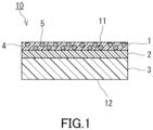
- a separation membrane 10 of the present embodiment includes a separation functional layer 1, an interlayer 2, and a porous support member 3 in this order in a stacking direction.
- the separation functional layer 1 allows, for example, water contained in a liquid mixture to permeate therethrough preferentially or selectively.
- the interlayer 2 is, for example, in direct contact with each of the separation functional layer 1 and the porous support member 3.
- the interlayer 2 has a thickness of 0.1 ⁇ m to 2.5 ⁇ m.
- the thickness of the interlayer 2 is preferably 2.3 ⁇ m or less, more preferably 2.0 ⁇ m or less, still more preferably 1.5 ⁇ m or less, and particularly preferably 1.0 ⁇ m or less.
- the thickness of the interlayer 2 may be 0.5 ⁇ m or more.
- the thickness of the interlayer 2 can be determined by the following method, for example. First, a cross-section of the separation membrane 10 is observed with a scanning electron microscope. Using an electron microscope image obtained, a distance between a pair of principal surfaces, of the interlayer 2, that face each other is measured at a plurality of arbitrary points (at least three points). An average of the obtained values can be assumed as the thickness of the interlayer 2.
- the term "principal surface” means a surface, of the interlayer 2, that has a largest area.
- a total value T of the thickness of the interlayer 2 and a thickness of the separation functional layer 1 is less than 4.0 ⁇ m.
- the thickness of the separation functional layer 1 is not particularly limited as long as the total value T is less than 4.0 ⁇ m.
- the thickness of the separation functional layer 1 is 0.1 ⁇ m to 2.5 ⁇ m, for example, and it is preferably 2.3 ⁇ m or less, more preferably 2.0 ⁇ m or less, still more preferably 1.8 ⁇ m or less, and particularly preferably 1.5 ⁇ m or less.
- the thickness of the separation functional layer 1 may be 0.5 ⁇ m or more.
- the thickness of the separation functional layer 1 can be determined by the method mentioned above for the interlayer 2.
- the total value T of the thickness of the interlayer 2 and the thickness of the separation functional layer 1 is preferably 3.5 ⁇ m or less, more preferably 3.3 ⁇ m or less, still more preferably 3.0 ⁇ m or less, particularly preferably 2.8 ⁇ m or less, and especially preferably 2.5 ⁇ m or less.
- the lower limit of the total value T is not particularly limited and it is 0.5 ⁇ m, for example, and it is preferably 1.0 ⁇ m and more preferably 1.5 ⁇ m.
- a ratio R of the thickness of the separation functional layer 1 with respect to the thickness of the interlayer 2 is not particularly limited and it is 10 or less, for example, and it is preferably 5.0 or less, more preferably 3.0 or less, still more preferably 2.0 or less, and particularly preferably 1.0 or less.
- the lower limit of the ratio R is not particularly limited, and it is 0.1, for example. It may be 0.3, 0.5, or 0.6 in some cases.
- the separation functional layer 1 has a matrix 4 and a filler 5, for example.
- the filler 5 is dispersed in the matrix 4 and is buried in the matrix 4. In the embodiment shown in FIG. 1 , all particles of the filler 5 are spaced apart from each other. The filler 5 may be condensed partially.
- the separation functional layer 1 may not include the filler 5.
- the matrix 4 contains polyimide.
- polyimide (P) including a structural unit represented by formula (1) below can be mentioned, for example.
- A is, for example, a linking group having a solubility parameter, in accordance with a Fedors method, of more than 5.0 (cal/cm 3 ) 1/2 .
- the "solubility parameter in accordance with a Fedors method” is also referred to as an SP value.
- the SP value of A is preferably 8.5 (cal/cm 3 ) 1/2 or more, more preferably 11.0 (cal/cm 3 ) 1/2 or more, and still more preferably 12.0 (cal/cm 3 ) 1/2 or more.
- the upper limit of the SP value of A is not particularly limited, and it may be 30.0 (cal/cm 3 ) 1/2 , for example.
- Preferable examples of the SP value of A include 12.0 (cal/cm 3 ) 1/2 and 12.68 (cal/cm 3 ) 1/2 .
- A includes, for example, at least one selected from the group consisting of an oxygen atom, a nitrogen atom, a sulfur atom, and a silicon atom.
- A includes at least one selected from the group consisting of an oxygen atom and a nitrogen atom.
- A includes an oxygen atom.
- A includes, for example, at least one functional group selected from the group consisting of an ether group, an ester group, a ketone group, a hydroxy group, an amide group, a thioether group, and a sulfonyl group.
- A includes at least one selected from the group consisting of an ether group and an ester group.
- A may include another group, such as a hydrocarbon group, besides the above-mentioned functional groups.
- the number of carbon atoms that the hydrocarbon group has is not particularly limited, and it is 1 to 15, for example.
- the number of carbon atoms may be 1 to 3, or may be 6 to 15.
- the valence of the hydrocarbon group is not particularly limited, either.
- the hydrocarbon group is a divalent hydrocarbon group.
- divalent hydrocarbon group examples include a methylene group, an ethylene group, a propane-1,3-diyl group, a propane-2,2-diyl group, a butane-1,4-diyl group, a pentane-1,5-diyl group, a 2,2-dimethylpropane-1,3-diyl group, a 1,4-phenylene group, a 2,5-di-tert-butyl-1,4-phenylene group, a 1-methyl-1,1-ethanediylbis(1,4-phenylene) group, and a biphenyl-4,4'-diyl group.
- at least one hydrogen atom included in these hydrocarbon groups may be substituted by a halogen atom.
- A is a linking group represented by, for example, a general formula -O-R 19 -O- or a general formula -COO-R 20 -OOC-.
- R 19 and R 20 each are a divalent hydrocarbon group having 1 to 15 carbon atoms.
- the divalent hydrocarbon group the divalent hydrocarbon groups stated above can be mentioned.
- A may not include the above-mentioned functional groups.
- Examples of such A include an alkylene group.
- the number of carbon atoms that the alkylene group has is not particularly limited, and it may be 1 to 15, for example, and it may be 1 to 5.
- the alkylene group may be branched, but preferably it is linear.
- a part of hydrogen atoms included in the alkylene group may be substituted by a halogen atom.
- the alkylene group be an alkylene group without the substitution, that is, a linear or branched alkylene group.
- the number of atoms constituting a bonding chain, among bonding chains that bond two phthalimide structures linked to each other by A, that is composed of a least number of atoms is 2 or more, for example, and it is preferably 4 or more, and more preferably 6 to 11.
- the bonding chain composed of a least number of atoms is also referred to as a "shortest bonding chain".
- A is an o-phenylene group
- the number of atoms constituting a shortest bonding chain that bonds two phthalimide structures linked to each other by A is 2.
- A is a p-phenylene group
- the number of atoms constituting a shortest bonding chain that bonds two phthalimide structures linked to each other by A is 4.
- A may be one of the linking groups 1 to 26 shown in Tables 1 and 2 below. Tables 1 and 2 show the chemical structure, the SP value, and the number of atoms constituting a shortest bonding chain of each of the linking groups 1 to 26.
- A is preferably the linking group 11 or the linking group 18, and particularly preferably the linking group 18.
- the polyimide (P) is easily dissolved in a polar organic solvent, such as N-methyl-2-pyrrolidone (NMP) and 1,3-dioxolane, and is easily adopted in a method desirable for manufacturing the separation functional layer 1.
- NMP N-methyl-2-pyrrolidone
- B is, for example, a linking group having an SP value more than 8.56 (cal/cm 3 ) 1/2 . Water tends to penetrate into the separation functional layer 1 easily when the SP value of the linking group B is more than 8.56 (cal/cm 3 ) 1/2 .
- the SP value of B is preferably 9.0 (cal/cm 3 ) 1/2 or more, more preferably 11.0 (cal/cm 3 ) 1/2 or more, still more preferably 12.0 (cal/cm 3 ) 1/2 or more, and particularly preferably 14.0 (cal/cm 3 ) 1/2 or more.
- the upper limit of the SP value of B is not particularly limited, and it may be 30.0 (cal/cm 3 ) 1/2 , for example.
- Preferable examples of the SP value of B include 14.0 (cal/cm 3 ) 1/2 and 14.51 (cal/cm 3 ) 1/2 .
- B includes, for example, at least one selected from the group consisting of an oxygen atom, a nitrogen atom, a sulfur atom, and a silicon atom.
- B includes at least one selected from the group consisting of an oxygen atom and a nitrogen atom.
- B includes an oxygen atom.
- B includes, for example, at least one functional group selected from the group consisting of an ether group, an ester group, a ketone group, a hydroxy group, an amide group, a thioether group, and a sulfonyl group.
- B includes an ether group.
- B may include another group, such as a hydrocarbon group, besides the above-mentioned functional groups.
- a hydrocarbon group the hydrocarbon groups stated above for A can be mentioned.
- B may be identical to or different from A.
- the number of atoms constituting a bonding chain (a shortest bonding chain), among bonding chains that bond Ar 1 and Ar 2 linked to each other by B, that is composed of a least number of atoms is 1 or more, for example.
- the upper limit of the number of atoms constituting the shortest bonding chain is not particularly limited, and it is 12, for example.
- the number of atoms constituting the shortest bonding chain is 1.
- B may be one of the linking groups 5 to 26 shown in the above-mentioned Tables 1 and 2.
- B is preferably the linking group 9, the linking group 16, or the linking group 21, and particularly preferably the linking group 21.
- R 1 to R 6 each are independently a hydrogen atom, a halogen atom, a hydroxy group, a sulfonic group, an alkoxy group having 1 to 30 carbon atoms, or a hydrocarbon group having 1 to 30 carbon atoms.
- R 1 to R 6 each are a hydrogen atom.
- the alkoxy group or the hydrocarbon group as R 1 to R 6 may be either linear or branched.
- the number of carbon atoms that the alkoxy group or the hydrocarbon group has is preferably 1 to 20, more preferably 1 to 10, and particularly preferably 1 to 5.
- Examples of the alkoxy group include a methoxy group, an ethoxy group, and a propoxy group.
- the hydrocarbon group include a methyl group, an ethyl group, and a propyl group. At least one hydrogen atom included in the alkoxy group or the hydrocarbon group may be substituted by a halogen atom.
- R 2 and R 3 as well as R 5 and R 6 may be bond to each other to form a ring structure.
- the ring structure is a benzene ring, for example.
- Ar 1 and Ar 2 each are a divalent aromatic group.
- the divalent aromatic group includes an aromatic ring.
- a nitrogen atom in a phthalimide structure be bonded directly to the aromatic ring included in Ar 1 , or the aromatic ring included in Ar 2 .
- B may be bonded directly to both of the aromatic ring included in Ar 1 and the aromatic ring included in Ar 2 .
- the aromatic ring be composed of a carbon atom.
- the aromatic ring may be a heteroaromatic ring including a hetero atom such as an oxygen atom, a nitrogen atom, and a sulfur atom.
- the aromatic ring may be polycyclic, but preferably it is monocyclic.
- the number of carbon atoms that the aromatic ring has is not particularly limited, and it may be 4 to 14, for example, and it may be 6 to 10.
- aromatic ring examples include a benzene ring, a naphthalene ring, an anthracene ring, a phenanthrene ring, a furan ring, a pyrrole ring, a pyridine ring, and a thiophene ring.
- the aromatic ring may or may not have a substituent.
- substituent of the aromatic ring include a halogen atom, a hydroxy group, a sulfonic group, an alkoxy group having 1 to 30 carbon atoms, and a hydrocarbon group having 1 to 30 carbon atoms.
- the alkoxy group and the hydrocarbon group the alkoxy groups and the hydrocarbon groups stated above for R 1 to R 6 can be mentioned.
- the aromatic ring has a plurality of substituents, the substituents may be identical to or different from each other.
- Ar 1 and Ar 2 each are a phenylene group that may have a substituent, or a naphthalenediyl group that may have a substituent.
- Ar 1 and Ar 2 each may be represented by formula (2) below when Ar 1 and Ar 2 each are a phenylene group that may have a substituent.
- R 7 to R 10 each are independently a hydrogen atom, a halogen atom, a hydroxy group, a sulfonic group, an alkoxy group having 1to 30 carbon atoms, or a hydrocarbon group having 1 to 30 carbon atoms.
- the alkoxy group and the hydrocarbon group the alkoxy groups and the hydrocarbon groups stated above for R 1 to R 6 can be mentioned.
- R 7 to R 10 each are a hydrogen atom.
- the formula (2) represents a p-phenylene structure. Polyimide having the p-phenylene structure is less bulky three-dimensionally than polyimide having an o-phenylene structure or an m-phenylene structure, and is suitable for enhancing the separation performance of the separation membrane.
- the naphthalenediyl group, as Ar 1 and Ar 2 , that may have a substituent has a naphthalene-2,6-diyl structure, a naphthalene-1,4-diyl structure, a naphthalene-1,5-diyl structure, or a naphthalene-1,8-diyl structure, for example.
- the naphthalenediyl group that may have a substituent is a naphthalene-2,6-diyl group, for example.
- Ar 1 and Ar 2 may be identical to or different from each other.
- Ar 1 is a naphthalene-2,6-diyl group while Ar 2 is a p-phenylene group.
- the structural unit represented by the formula (1) is preferably a structural unit represented by formula (3) below.
- R 11 to R 18 each are independently a hydrogen atom, a halogen atom, a hydroxy group, a sulfonic group, an alkoxy group having 1 to 30 carbon atoms, and a hydrocarbon group having 1 to 30 carbon atoms.
- R 11 to R 18 each are preferably a hydrogen atom.
- a content of the structural unit represented by the formula (1) in the polyimide (P) is 50 mol% or more, for example, and it is preferably 60 mol% or more, more preferably 70 mol% or more, still more preferably 80 mol% or more, and particularly preferably 90 mol% or more.
- the content of the structural unit represented by the formula (1) may be 100 mol%.
- the structural unit represented by the formula (1) can be obtained by a reaction between tetracarboxylic dianhydride (C) represented by formula (4) below and a diamine compound (D) represented by formula (5) below.
- C tetracarboxylic dianhydride
- D diamine compound
- a as well as R 1 to R 6 are identical to those in the formula (1).
- B, Ar 1 , and Ar 2 are identical to those in the formula (1).
- the polyimide (P) may include a structural unit derived from an other tetracarboxylic dianhydride that is different from the tetracarboxylic dianhydride (C).
- the other tetracarboxylic dianhydride is not particularly limited, and a known tetracarboxylic dianhydride can be used.
- Examples of the other tetracarboxylic dianhydride include pyromellitic dianhydride, and 4,4'-(hexafluoroisopropylidene)diphthalic anhydride.
- a ratio P1 of a structural unit(s) derived from the tetracarboxylic dianhydride (C) with respect to structural units derived from all the tetracarboxylic dianhydrides is 50 mol% or more, for example, and it is preferably 70 mol% or more, and more preferably 90 mol% or more.
- the ratio P1 may be 100 mol%.
- the polyimide (P) may include a structural unit derived from an other diamine compound that is different from the diamine compound (D).
- the other diamine compound is not particularly limited and a known diamine compound can be used.
- the other diamine compound include phenylenediamine, diaminobenzoic acid, diaminobiphenyl, and diaminodiphenylmethane.
- the polyimide (P) may include a structural unit derived from diaminobenzoic acid (such as 3,5-diaminobenzoic acid).
- the polyimide (P) including the structural unit derived from diaminobenzoic acid is suitable for increasing a flux of the water permeating through the separation membrane 10.
- a ratio P2 of a structural unit(s) derived from the diamine compound (D) with respect to structural units derived from all the diamine compounds is 50 mol% or more, for example, and it is preferably 70 mol% or more, and more preferably 90 mol% or more.
- the ratio P2 may be 100 mol%.
- the polyimide (P) can be produced by the following method, for example.
- the diamine compound (D) is dissolved in a solvent to obtain a solution.
- the solvent include a polar organic solvent such as N-methyl-2-pyrrolidone (NMP) and 1,3-dioxolane.
- NMP N-methyl-2-pyrrolidone
- the tetracarboxylic dianhydride (C) is added gradually to the obtained solution. This makes the tetracarboxylic dianhydride (C) and the diamine compound (D) react with each other to form polyamide acid.
- the addition of the tetracarboxylic dianhydride (C) is carried out under the conditions, for example, that the solution is being stirred for 3 to 20 hours at a temperature equal to or lower than a room temperature (25°C).
- the polyamide acid is imidized to obtain the polyimide (P).
- the imidization method include a chemical imidization method and a thermal imidization method.
- the chemical imidization method is a method for imidizing polyamide acid using a dehydration condensation agent.
- the chemical imidization method may be carried out under a room temperature condition or a heat condition.
- Examples of the dehydration condensation agent include acetic anhydride, pyridine, and triethylamine.
- the thermal imidization method is a method for imidizing polyamide acid by a heat treatment. The heat treatment is carried out at a temperature of 180°C or higher, for example.
- a content of the polyimide (P) in the matrix 4 is 50 wt% or more, for example, and it is preferably 60 wt% or more, more preferably 70 wt% or more, still more preferably 80 wt% or more, and particularly preferably 90 wt% or more.
- the matrix 4 is composed substantially of the polyimide (P), for example.
- a content of the matrix 4 in the separation functional layer 1 is 70 wt% or more, for example.
- the upper limit of the content of the matrix 4 is not particularly limited, and it may be 99 wt% or 95 wt%.
- the filler 5 has hydrophilicity and is porous, for example.
- the filler 5 as just mentioned is suitable for increasing the flux of the water permeating through the separation membrane 10 without deteriorating the separation performance of the separation membrane 10 significantly.
- the filler 5 includes, for example, at least one selected from the group consisting of zeolite and a metal organic framework (MOF). From the viewpoint of durability against water, it is preferable that the filler 5 include the metal organic framework.
- MOF metal organic framework
- the filler 5 include the metal organic framework.
- molecular sieves 3A, 4A, 5A, and 13X can be mentioned, for example.
- the metal organic framework is also referred to as a porous coordination polymer (PCP).
- the metal organic framework includes a metal ion and an organic ligand, for example.
- the metal ion include a Co ion, an Ni ion, a Zn ion, an Mg ion, a Zr ion, and a Cu ion.
- the organic ligand may not have a polar group, but preferably it has a polar group. Examples of the polar group include an aldehyde group, an amino group, an amide group, a hydroxy group, a carboxyl group, and a nitro group.
- the organic ligand includes an aromatic ring, for example.
- Examples of the aromatic ring included in the organic ligand include a benzene ring and an imidazole ring.
- Examples of the organic ligand include 2-hydroxymethylimidazole, 2-formylimidazole, terephthalic acid, 2-hydroxyterephthalic acid, 2,5-dihydroxyterephthalic acid, and 2-aminoterephthalic acid.
- a filler that can adsorb water is suitable.
- a filler that adsorbs water better than it adsorbs ethanol is suitable as the filler 5.
- a ratio R1 of an adsorption amount Q2 of water adsorbed by the filler 5 under water vapor at 25°C and 3.2 kPa with respect to an adsorption amount Q1 of ethanol adsorbed by the filler 5 under an ethanol atmosphere at 25°C and 7.4 kPa is 2.0 or more, for example, and is preferably 3.0 or more.
- the upper limit of the ratio R1 is not particularly limited, and it is 5.0, for example.
- the ratio R1 is used as an index of hydrophilicity of the filler 5 in some cases.
- the term "adsorption amount" means a value obtained by converting a volume of a gas that 1 g of the filler 5 has adsorbed into a volume of the gas in a standard state (298 K, 1 atm).
- the adsorption amount Q1 of ethanol adsorbed by the filler 5 can be determined by the following method.
- this filler 5 is pretreated by being heated under a decompressed atmosphere.
- the pretreatment may be carried out under a vacuum atmosphere.
- the pretreatment is carried out at a temperature of 100°C or higher, for example.
- the duration of the pretreatment is not particularly limited, and it is 1 hour or longer, for example.
- the filler 5 is placed in a known vapor adsorption amount measuring apparatus such as BELSORP-maxII available from MicrotracBEL Corp.
- gaseous ethanol is introduced into the measuring apparatus at a measurement temperature of 25°C.
- the gaseous ethanol introduced is adsorbed by the filler 5.
- the gaseous ethanol is introduced until the pressure of the ethanol in the measuring apparatus reaches 7.4 kPa.
- the pressure of 7.4 kPa is equivalent to an equilibrium vapor pressure (a saturation vapor pressure) of ethanol at 25°C.
- the adsorption of the ethanol by the filler 5 is confirmed to have reached a state of equilibrium, and then the adsorption amount of the ethanol adsorbed by the filler 5 is determined.
- the fact that the adsorption of the ethanol by the filler 5 has reached a state of equilibrium can be confirmed by a change in the pressure of the ethanol inside the measuring apparatus.
- the adsorption of the ethanol by the filler 5 can be considered to have reached a state of equilibrium.
- the adsorption amount of the ethanol that is determined by the above-mentioned method can be assumed as the adsorption amount Q1.
- the adsorption amount Q2 of water adsorbed by the filler 5 can be determined by the following method. First, the filler 5 is subject to the pretreatment mentioned above. The filler 5 is placed in a vapor adsorption amount measuring apparatus. Next, water vapor is introduced into the measuring apparatus at a measurement temperature of 25°C. The water vapor is introduced until the pressure of the water vapor in the measuring apparatus reaches 3.2 kPa. The pressure of 3.2 kPa is equivalent to an equilibrium vapor pressure of water at 25°C. The adsorption of the water by the filler 5 is confirmed to have reached a state of equilibrium, and then the adsorption amount of the water adsorbed by the filler 5 is determined. The determined adsorption amount of the water can be assumed as the adsorption amount Q2.
- the adsorption amount Q1 of ethanol adsorbed by the filler 5 is 200 cm 3 /g or less, for example.
- the lower limit of the adsorption amount Q1 is not particularly limited, and it may be 90 cm 3 /g or 100 cm 3 /g.
- the adsorption amount Q2 of water adsorbed by the filler 5 is 300 cm 3 /g or more, for example, and it may be 350 cm 3 /g or more, 450 cm 3 /g or more, 500 cm 3 /g or more, or 550 cm 3 /g or more in some cases.
- the upper limit of the adsorption amount Q2 is not particularly limited, and it is 800 cm 3 /g, for example.
- the filler 5 may be a filler in which a ratio R2 of a BET (Brunauer-Emmett-Teller) specific surface area S2 obtained by water vapor adsorption with respect to a BET specific surface area S1 obtained by nitrogen gas adsorption is 0.005 or more.
- the ratio R2 is used as an index of hydrophilicity of the filler 5 in some cases.
- the ratio R2 is 0.01 or more, for example, and it is preferably 0.1 or more, more preferably 0.2 or more, and still more preferably 0.3 or more.
- the ratio R2 may be 25 or less, 10 or less, 1.0 or less, or 0.6 or less.
- the BET specific surface area S1 obtained by nitrogen gas adsorption is 1500 m 2 /g or less, for example, and it is preferably 1000 m 2 /g or less. It may be 900 m 2 /g or less in some cases.
- the specific surface area S1 may be 30 m 2 /g or more, or 400 m 2 /g or more.
- the BET specific surface area S2 obtained by water vapor adsorption is 10 m 2 /g or more, for example, and it is preferably 100 m 2 /g or more, and more preferably 150 m 2 /g or more. It may be 200 m 2 /g or more in some cases.
- the specific surface area S2 may be 1000 m 2 /g or less, 600 m 2 /g or less, or 400 m 2 /g or less.
- the filler 5 has a shape that is not particularly limited, and it is a particulate shape, for example.
- the "particulate” is a shape such as a spherical shape, an elliptical shape, a flaky shape, and a fibrous shape.
- the filler 5 has an average particle diameter that is not particularly limited, and it is 5 nm to 10000 nm, for example.
- the average particle diameter of the filler 5 can be determined by the following method, for example. First, a cross section of the separation functional layer 1 is observed with a transmission electron microscope. On an electron microscope image obtained, an area of a particular particle of the filler 5 is calculated by image processing.
- a diameter of a circle having an area equal to the calculated area is assumed as a diameter of that particular particle (a diameter of a particle) of the filler 5.
- a particle diameter of each of an arbitrary number (at least 50) of particles of the filler 5 is calculated.
- An average of the calculated values is assumed as the average particle diameter of the filler 5.
- a content of the filler 5 in the separation functional layer 1 may be 1 wt% or more, 5 wt% or more, 10 wt% or more, 15 wt% or more, or 20 wt% or more, for example.
- the content of the filler 5 in the separation functional layer 1 may be 30 wt% or less.
- the interlayer 2 contains a polymer compound (E), for example.
- a distance Ra between a Hansen solubility parameter of the polymer compound (E) and a Hansen solubility parameter of H 2 O be less than 19 MPa 1/2 .
- the interlayer 2 containing the polymer compound (E) as just mentioned is suitable for inhibiting the flux of the water permeating through the separation membrane 10 from decreasing.
- the polymer compound (E) is suitable for inhibiting the occurrence of defects in the interlayer 2 at the time of producing the interlayer 2 while adjusting the thickness of the interlayer 2 to 2.5 ⁇ m or less.
- the interlayer 2 containing the polymer compound (E) also has an advantage that the separation functional layer 1 containing polyimide and having a thickness of about 2.5 ⁇ m or less can be formed easily on a surface of the interlayer 2. It should be noted that the above-mentioned distance Ra may be 19 MPa 1/2 or more depending on a composition of the separation functional layer 1, the use of the separation membrane, etc.
- the present invention provides, from another aspect, the separation membrane 10 including the separation functional layer 1, the interlayer 2, and the porous support member 3 in this order in a stacking direction, wherein
- the Hansen solubility parameter is a parameter obtained by dividing a solubility parameter introduced by Hildebrand into three components of a dispersion term ⁇ D, a polar term ⁇ P, and a hydrogen bond term ⁇ H.
- the details of the Hansen solubility parameter are disclosed in " Hansen Solubility Parameters; A Users Handbook” (CRC Press, 2007 ).
- the Hansen solubility parameter can be calculated by, for example, using a known software such as HSPiP.
- the distance Ra between the Hansen solubility parameter of the polymer compound (E) and the Hansen solubility parameter of H 2 O can be calculated by formula (i) below.
- ⁇ D 1 , ⁇ P 1 , and ⁇ H 1 are, respectively, a dispersion term (MPa 1/2 ), a polar term (MPa 1/2 ), and a hydrogen bond term (MPa 1/2 ) of the polymer compound (E).
- ⁇ D 2 , ⁇ P 2 , and ⁇ H 2 are respectively a dispersion term (18.1 MPa 1/2 ), a polar term (17.1 MPa 1/2 ), and a hydrogen bond term (16.9 MPa 1/2 ) of H 2 O.
- Ra 4 ⁇ ⁇ D 1 ⁇ ⁇ D 2 2 + ⁇ P 1 ⁇ ⁇ P 2 2 + ⁇ H 1 ⁇ ⁇ H 2 2 1 / 2
- the distance Ra between the Hansen solubility parameter of the polymer compound (E) and the Hansen solubility parameter of H 2 O is preferably 18 MPa 1/2 or less, more preferably 17 MPa 1/2 or less, still more preferably 16 MPa 1/2 or less, and particularly preferably 15 MPa 1/2 or less.
- the lower limit of the distance Ra is preferably 5 MPa 1/2 , and more preferably 8 MPa 1/2 . It may be 10 MPa 1/2 or 13 MPa 1/2 in some cases.
- the polymer compound (E) contains, for example, at least one selected from the group consisting of polyether block amide, polyvinyl alcohol (PVA), polyether, and polyurethane.
- polyether polyethylene glycol (PEG) can be mentioned, for example.
- the polymer compound (E) may include silicone polymer, such as dimethylpolysiloxane, in some cases.
- the polyether block amide is a block copolymer containing a polyether block PE and a polyamide block PA.
- the polyether block amide is represented by formula (6) below, for example.
- R 21 is a divalent hydrocarbon group having 1 to 15 carbon atoms.
- the number of carbon atoms that the divalent hydrocarbon group has may be 1 to 10 or 1 to 5.
- the divalent hydrocarbon group is preferably an alkylene group that is linear or branched. Specific examples of R 21 are an ethylene group and a butane-1,4-diyl group.
- R 22 is a divalent hydrocarbon group having 1 to 20 carbon atoms. As for R 22 , the number of carbon atoms that the divalent hydrocarbon group has may be 3 to 18, or 3 to 15.
- the divalent hydrocarbon group is preferably an alkylene group that is linear or branched. Specific examples of R 22 are a pentane-1,5-diyl group and an undecane-1,11-diyl group.
- a ratio (x:y) between x and y is 1:9 to 9:1, for example, and it is preferably 5:5 to 9:1, and more preferably 6:4 to 8:2.
- the letter n refers to an integer of 1 or more.
- Pebax registered trademark
- 1657 available from Arkema
- Table 3 below shows specific examples 1 to 5 of the polymer compound (E). Table 3 also shows the Hansen solubility parameter and the above-mentioned distance Ra of each of the specific examples 1 to 5.
- the interlayer 2 may contain the polymer compound (E), particularly the polyether block amide, as a main component, and a content thereof is 50 wt% or more, for example, and it is preferably 60 wt% or more, more preferably 70 wt% or more, still more preferably 80 wt% or more, and particularly preferably 90 wt% or more.
- the interlayer 2 is composed substantially of the polymer compounds (E).
- the porous support member 3 is not particularly limited as long as it can support the separation functional layer 1 and the interlayer 2.
- the porous support member 3 include: a nonwoven fabric; porous polytetrafluoroethylene; aromatic polyamide fiber; a porous metal; a sintered metal; porous ceramic; porous polyester; porous nylon; activated carbon fiber; latex; silicone; silicone rubber; a permeable (porous) polymer including at least one selected from the group consisting of polyvinyl fluoride, polyvinylidene fluoride, polyurethane, polypropylene, polyethylene, polycarbonate, polysulfone, polyether ether ketone, polyacrylonitrile, polyimide, and polyphenylene oxide; a metallic foam having an open cell or a closed cell; a polymer foam having an open cell or a closed cell; silica; porous glass; and a mesh screen.
- the porous support member 3 may be a combination of two or more of these materials.
- the porous support member 3 has an average pore diameter of 0.01 to 0.4 ⁇ m, for example.
- the porous support member 3 has a thickness that is not particularly limited. It is 10 ⁇ m or more, for example, and it is preferably 20 ⁇ m or more, and more preferably 50 ⁇ m or more.
- the thickness of the porous support member 3 is 300 ⁇ m or less, for example, and it is preferably 200 ⁇ m or less, and more preferably 75 ⁇ m or less.
- the separation membrane 10 can be produced by the following method, for example.
- a coating liquid containing the polymer compound (E) is prepared.
- a solvent of the coating liquid include an organic solvent such as 2-propanol (IPA).
- a concentration of the polymer compound (E) in the coating liquid is not particularly limited, and it is 1 wt% to 10 wt%, for example, and it is preferably 3 wt% to 7wt%.
- the solvent may be heated beforehand.
- the temperature at which the solvent is heated is not particularly limited as long as it is equal to or lower than a boiling point of the solvent, and it is 30°C to 80°C, for example.
- the coating liquid is applied onto the porous support member 3 to obtain a coating.
- the coating is dried to form the interlayer 2.
- the thickness of the interlayer 2 can be adjusted by the concentration of the polymer compound (E) in the coating liquid and a thickness of the coating.
- a coating liquid containing the filler 5 and a material of the matrix 4 is prepared.
- an organic solvent such as 1,3-dioxolane
- the coating liquid may be subject to ultrasonication in order to enhance the dispersibility of the filler 5 in the coating liquid.
- the coating liquid is applied onto the interlayer 2 to obtain a coating.
- the coating is dried to form the separation functional layer 1. Thereby, the separation membrane 10 can be produced.
- the material of the matrix 4 contained in the coating liquid may be polyamide acid.
- the separation functional layer 1 can be formed by imidizing the polyamide acid after applying the coating liquid onto the interlayer 2.
- a viscosity of a coating liquid for forming the separation functional layer In order to form a thin separation functional layer, it can be considered to adjust a viscosity of a coating liquid for forming the separation functional layer to be relatively low, for example, to 10 mPa•s or less.
- a coating liquid including a filler tends to have a low viscosity.
- this coating liquid enters into the porous support member easily.
- the entry of the coating liquid into the porous support member makes it difficult for a coating to be formed uniformly on a surface of the porous support member, and defects tend to occur in the obtained separation functional layer.
- defects also tend to occur in the separation functional layer when a surface of the porous support member has a defect and a coating liquid for forming the separation functional layer is applied directly onto this surface.
- the coating liquid for forming the separation functional layer 1 is applied not onto the porous support member 3 but onto the interlayer 2, and thus the coating liquid is unlikely to enter into the porous support member 3. Therefore, even in the cases where the coating liquid has a relatively low viscosity and where a surface of the porous support member 3 has a defect, it is possible to inhibit sufficiently defects from occurring in the separation functional layer 1.
- the number of the defects in the separation functional layer 1 per 1000 cm 2 of a surface of the separation functional layer 1 is 10 or less, for example, and it is preferably five or less, more preferably two or less, and still more preferably zero.
- the thickness of the interlayer 2 as well as the total value T of the thickness of the interlayer 2 and the thickness of the separation functional layer 1 are adjusted properly. Thereby, the flux of the permeation fluid permeating through the separation membrane 10 is inhibited from decreasing.
- a flux F of the water permeating through the separation membrane 10 is 0.30 kg/m 2 /hr or more, for example, and it is preferably 0.35 kg/m 2 /hr or more, more preferably 0.40 kg/m 2 /hr or more, still more preferably 0.45 kg/m 2 /hr or more, and particularly preferably 0.50 kg/m 2 /hr or more.
- the upper limit of the flux F of the water is not particularly limited, and it is 1.00 kg/m 2 /hr, for example.
- the flux F of the water can be measured by the following method. First, in a state in which a liquid mixture composed of ethanol and water is in contact with one surface (a principal surface 11, on a side of the separation functional layer, of the separation membrane 10, for example) of the separation membrane 10, a space adjacent to an other surface (a principal surface 12, on a side of the porous support member, of the separation membrane 10, for example) of the separation membrane 10 is decompressed. Thereby, a permeation fluid that has permeated through the separation membrane 10 can be obtained. In the above-mentioned procedure, a concentration of the ethanol in the liquid mixture is 50 vol% (44 wt%) when measured with a temperature of the liquid mixture at 20°C.
- the liquid mixture in contact with the separation membrane 10 has a temperature of 60°C.
- the space adjacent to the other surface of the separation membrane 10 is decompressed in such a manner that a pressure in the space is lower than an atmospheric pressure in a measurement environment by 100 kPa.
- a weight of the permeation fluid and a weight ratio of the water in the permeation fluid are measured.
- the flux F of the water can be determined based on the obtained results.
- a separation factor ⁇ that the separation membrane 10 has for water with respect to ethanol is 20 or more, for example, and it is preferably 40 or more, and more preferably 45 or more. It may be 50 or more, 60 or more, or 65 or more in some cases.
- the upper limit of the separation factor ⁇ is not particularly limited, and it is 500, for example.
- the separation membrane 10 having the separation factor ⁇ that is 20 or more is sufficiently suitable to be used for separating water from a liquid mixture containing an alcohol and water.
- the separation membrane 10 of the present embodiment is used for, for example, separating water from a liquid mixture containing an alcohol and water. In this use, the flux of the water permeating through the separation membrane 10 tends to be high. However, the use of the separation membrane 10 is not limited to the above-mentioned use of separating water from a liquid mixture.
- a membrane separation device 100 of the present embodiment is provided with the separation membrane 10 and a tank 20.
- the tank 20 is provided with a first room 21 and a second room 22.
- the separation membrane 10 is disposed in the tank 20.
- the separation membrane 10 separates the first room 21 from the second room 22.
- the tank 20 has a pair of wall surfaces, and the separation membrane 10 extends from one of them to the other.
- the first room 21 has an inlet 21a and an outlet 21b.
- the second room 22 has an outlet 22a.
- the inlet 21a, the outlet 21b, and the outlet 22a each are an opening formed in the wall surfaces of the tank 20, for example.
- Membrane separation using the membrane separation device 100 is carried out by the following method, for example.
- a liquid mixture 30 containing an alcohol and water is supplied into the first room 21 via the inlet 21a. This makes it possible to bring the liquid mixture 30 into contact with one surface of the separation membrane 10.
- the alcohol contained in the liquid mixture 30 is, for example, a lower alcohol that exhibits azeotropy with water.
- the alcohol is preferably ethanol, and it may be isopropyl alcohol (IPA).
- a concentration of the alcohol in the liquid mixture 30 is 10 wt% or more, for example, and it is preferably 20 wt% or more.
- the separation membrane 10 is particularly suitable for separating the water from the liquid mixture 30 containing the alcohol at a moderate concentration (20 wt% to 80 wt%, particularly 30 wt% to 70 wt%). It should be noted that the concentration of the alcohol in the liquid mixture 30 may be 80 wt% or more.
- the liquid mixture 30 may be composed substantially of the alcohol and water. A temperature of the liquid mixture 30 may be higher than a boiling point of the alcohol to be used. Preferably, the temperature is lower than the boiling point of the alcohol.
- the temperature of the liquid mixture 30 is 25°C or higher, for example, and it is preferably 40°C or higher, and more preferably 60°C or higher.
- the temperature of the liquid mixture 30 may be 75°C or lower.
- a space adjacent to an other surface of the separation membrane 10 is decompressed.
- an inside of the second room 22 is decompressed via the outlet 22a.
- the membrane separation device 100 may be further provided with a pump (not shown) for decompressing the inside of the second room 22.
- the second room 22 is decompressed in such a manner that a space in the second room 22 has a pressure lower than an atmospheric pressure in a measurement environment by 10 kPa or more, for example, and preferably by 50 kPa or more, and more preferably by 100 kPa or more.
- Decompressing the inside of the second room 22 makes it possible to obtain, on a side of the other surface of the separation membrane 10, a permeation fluid 35 having a content of the water higher than a content of the water in the liquid mixture 30. That is, the permeation fluid 35 is supplied into the second room 22.
- the permeation fluid 35 contains the water as a main component, for example.
- the permeation fluid 35 may contain a small amount of the alcohol besides the water.
- the permeation fluid 35 may be a gas or a liquid.
- the permeation fluid 35 is discharged to an outside of the tank 20 via the outlet 22a.
- the concentration of the alcohol in the liquid mixture 30 increases gradually from the inlet 21a toward the outlet 21b of the first room 21.
- the liquid mixture 30 (a concentrated fluid 36) processed in the first room 21 is discharged to the outside of the tank 20 via the outlet 21b.
- the membrane separation device 100 of the present embodiment is used preferably for a pervaporation method.
- the membrane separation device 100 may be used for other membrane separation methods such as a vapor permeation method. That is, a mixture gas containing a gaseous alcohol and gaseous water may be used instead of the liquid mixture 30 in the membrane separation method mentioned above.
- the membrane separation device 100 of the present embodiment is suitable for a flow-type (continuous-type) membrane separation method.
- the membrane separation device 100 of the present embodiment may be used for a batch-type membrane separation method.
- a membrane separation device 110 of the present embodiment is provided with a central tube 41 and a laminate 42.
- the laminate 42 includes the separation membrane 10.
- the membrane separation device 110 is a spiral membrane element.
- the central tube 41 has a cylindrical shape.
- the central tube 41 has a surface with a plurality of pores formed therein to allow the permeation fluid 35 to flow into the central tube 41.
- Examples of a material of the central tube 41 include: a resin such as an acrylonitrile-butadiene-styrene copolymer (an ABS resin), a polyphenylene ether resin (a PPE resin), and a polysulfone resin (a PSF resin); and a metal such as stainless steel and titanium.
- the central tube 41 has an inner diameter in a range of 20 to 100 mm, for example.
- the laminate 42 further includes a supply-side flow passage material 43 and a permeation-side flow passage material 44 besides the separation membrane 10.
- the laminate 42 is wound around a circumference of the central tube 41.
- the membrane separation device 110 may be further provided with an exterior material (not shown).
- a resin net composed of polyphenylene sulfide (PPS) or an ethylene-chlorotrifluoroethylene copolymer (ECTFE) can be used, for example.
- Membrane separation using the membrane separation device 110 is carried out by the following method, for example.
- the liquid mixture 30 (the concentrated fluid 36) processed by the membrane separation device 110 is discharged to the outside from an other end of the wound laminate 42. Thereby, the water can be separated from the liquid mixture 30.
- polyether block amide (Pebax (registered trademark) 2533 available from Arkema) was dissolved in IPA at 80°C to prepare a coating liquid.
- a concentration of the polyether block amide in the coating liquid was 3 wt%.
- the coating liquid was applied onto a porous support member to obtain a coating.
- a porous support member a UF membrane (ultrafiltration membrane) RS-50 (a laminate of a PVDF porous layer and a PET nonwoven fabric) available from Nitto Denko Corporation was used.
- the coating was formed on the PVDF porous layer of the RS-50.
- the application of the coating liquid was carried out using an applicator with a gap of 155 ⁇ m.
- the coating was dried to form an interlayer with a thickness of 0.5 ⁇ m.
- the tetracarboxylic dianhydride was added to the obtained solution under a room temperature condition to obtain polyamide acid.
- the polyamide acid was chemically imidized using triethylamine and acetic anhydride to obtain polyimide.
- the chemical imidization was carried out in N-methyl-2-pyrrolidone under a temperature condition of 60°C.
- a ratio of structural units derived from the 3,5-diaminobenzoic acid with respect to structural units derived from all the diamine compounds was 10 mol%.
- the polyimide was dissolved in 1,3-dioxolane to obtain a solution.
- the polyimide solution was added to a dispersion containing molecular sieve 4A (Zeoal4A (with a particle diameter of 300 nm) available from Nakamura Choukou Co., Ltd.), and these were mixed.
- the obtained coating liquid was applied onto the interlayer to obtain a coating.
- the coating was dried to form a separation functional layer with a thickness of 1.25 ⁇ m.
- a content of the polyimide in the separation functional layer was 80 wt%, and a content of the molecular sieve 4A was 20 wt%. Thereby, a separation membrane of Example 1 was obtained.
- Separation membranes of Examples 2 to 5 and 8 to 11 were obtained in the same manner as in Example 1, except that the thickness of the separation functional layer and the thickness of the interlayer were changed to the values shown in Table 4.
- the thickness of the interlayer was adjusted depending on the concentration of the polyether block amide in the coating liquid.
- the thickness of the separation functional layer was adjusted depending on a solid content concentration of the coating liquid.
- Separation membranes of Examples 6 and 12 were obtained in the same manner as in Example 1, except that Pebax (registered trademark) 1657 available from Arkema was used as the polyether block amide, and the thickness of the separation functional layer and the thickness of the interlayer were changed to the values shown in Table 4.
- Pebax registered trademark 1657 available from Arkema
- a separation membrane of Example 7 was obtained in the same manner as in Example 1, except that the interlayer was omitted and the thickness of the separation functional layer was changed to the value shown in Table 4.
- a coating liquid containing silicone polymer was prepared.
- a distance Ra between a Hansen solubility parameter of the silicone polymer and a Hansen solubility parameter of H 2 O was 19 MPa 1/2 or more.
- a content of the silicone polymer in the coating liquid was 2 wt%.
- the coating liquid was applied onto a porous support member to obtain a coating.
- a porous support member a UF membrane (ultrafiltration membrane) RS-50 (a laminate of a PVDF porous layer and a PET nonwoven fabric) available from Nitto Denko Corporation was used.
- the coating was formed on the PVDF porous layer of the RS-50.
- the application of the coating liquid was carried out using an applicator with a gap of 130 ⁇ m.
- the coating was dried to form an interlayer with a thickness of 1.8 ⁇ m.
- the number of defects in the separation functional layer was confirmed by the following method. First, a coloring material was dissolved in ethanol to produce a coloring liquid. This coloring liquid was applied onto the separation functional layer. Here, the coloring liquid entered into the separation functional layer at locations at which defects (pinholes) were present and colored such locations of the separation functional layer. Next, a surface of the separation functional layer was washed with ethanol. The number of the locations (colored locations) at which the coloring liquid entered into the separation functional layer was confirmed visually. Thereby, the number of the defects in the separation functional layer per 1000 cm 2 of the surface of the separation functional layer was determined.
- the flux F of the water permeating through the separation membrane and the separation factor ⁇ were measured by the following method.
- the separation membrane was placed in a metal cell, and the metal cell was sealed with an O-ring so that no leakage occurred.
- 250 mL of a liquid mixture was injected into the metal cell in such a manner that the liquid mixture was in contact with a principal surface, on a side of the separation functional layer, of the separation membrane.
- the liquid mixture was composed substantially of ethanol and water. A concentration of the ethanol in the liquid mixture was 50 vol% when measured with a temperature of the liquid mixture at 20°C.
- the metal cell was heated to 60°C in a water bath.
- the temperature of the liquid mixture in the metal cell was confirmed to be 60°C, and then a space, in the metal cell, that is adjacent to a principal surface, on a side of the porous support member, of the separation membrane was decompressed. This space was decompressed in such a manner that a pressure in the space was lower than an atmospheric pressure in a measurement environment by 100 kPa. Thereby, a gaseous permeation fluid was obtained.
- the gaseous permeation fluid was cooled using -196°C liquid nitrogen to liquefy the permeation fluid.
- a composition of the liquid permeation fluid was analyzed using gas chromatography (GC-3200 available from GL Sciences Inc.).
- the flux of the water that had permeated through the separation membrane and the separation factor ⁇ of the separation membrane were calculated based on the composition of the permeation fluid, a weight of the permeation fluid, etc.
- Example 7 a plurality of samples each obtained by cutting out a portion, of the separation functional layer, in which no defects were present as well as a plurality of samples each obtained by cutting out a portion, of the separation functional layer, in which defects were present were prepared, and each of these samples was subject to the above-mentioned measurements.
- the flux F of the water on Example 7 was an average value (0.57 kg/m 2 /hr) of the fluxes of the water determined by these samples.
- Table 4 shows a minimum value (9.2) and a maximum (85.5) of the separation factor ⁇ determined by these samples of Example 7.
- Material of interlayer Thickness of separation functional layer [ ⁇ m] Thickness of interlayer [ ⁇ m] Total value T of thickness of interlayer and thickness of separation functional layer [ ⁇ m] The number of defects in separation functional layer [defects/1000 cm 2 ] Separation performance Flux F of water [kg/m 2 /hr] Separation factor ⁇
- Example 1 Pebax2533 1.25 0.5 1.75 0 0.54 60.5
- Example 3 Pebax2533 0.7 1.43 2.13 0 0.58 56.3
- Example 5 Pebax2533 0.7 2.5 3.2 0 0.51 47.0
- Example 6 Pebax1657 1.0 1.5 2.5 0 0.60 76.0
- Example 7 Pebax2533 1.05
- the separation membrane of the present embodiment is suitable for separating water from a liquid mixture containing an alcohol and water. Particularly, the separation membrane of the present embodiment is useful for refining bioethanol.
Landscapes
- Chemical & Material Sciences (AREA)
- Chemical Kinetics & Catalysis (AREA)
- Engineering & Computer Science (AREA)
- Water Supply & Treatment (AREA)
- Inorganic Chemistry (AREA)
- Dispersion Chemistry (AREA)
- Life Sciences & Earth Sciences (AREA)
- Hydrology & Water Resources (AREA)
- Environmental & Geological Engineering (AREA)
- Organic Chemistry (AREA)
- Manufacturing & Machinery (AREA)
- Separation Using Semi-Permeable Membranes (AREA)
Abstract
Description
- The present invention relates to a separation membrane.
- A pervaporation method and a vapor permeation method have been developed as methods for separating water from a liquid mixture containing an alcohol and water. These methods are particularly suitable for separating water from an azeotropic mixture such as a liquid mixture containing ethanol and water. The pervaporation method is also characterized in that it does not require the liquid mixture to be evaporated before being treated.
- As a separation membrane used for the pervaporation method, a composite membrane obtained by forming a separation functional layer on a porous support member can be mentioned. In the field of separation membranes, an interlayer is disposed between a separation functional layer and a porous support member to reduce a thickness of the separation functional layer in some cases (such as Patent Literature 1).
- Patent Literature 1:
JP 1986-54222 A - In the case where a separation functional layer is formed directly on a porous support member, defects, such as a pinhole, tend to occur in the separation functional layer. The occurrence of the defects in the separation functional layer deteriorates the performance, particularly the separation performance, of the separation membrane significantly.
- In the case where an interlayer is disposed between a separation functional layer and a porous support member, the occurrence of the defects in the separation functional layer tends to be inhibited at the time of producing the separation functional layer. However, a separation membrane including an interlayer tends to decrease a flux of a permeation fluid permeating through the separation membrane.
- Therefore, the present invention is intended to provide a separation membrane that allows a separation functional layer to have less defects and that inhibits a flux of a permeation fluid from decreasing.
- The present invention provides a separation membrane including a separation functional layer, an interlayer, and a porous support member in this order in a stacking direction, wherein
- the interlayer has a thickness of 0.1 µm to 2.5 µm, and
- a total value of the thickness of the interlayer and a thickness of the separation functional layer is less than 4.0 µm.
- The present invention further provides a separation membrane including a separation functional layer, an interlayer, and a porous support member in this order in a stacking direction, wherein
- the interlayer contains a polymer compound, and
- a distance Ra between a Hansen solubility parameter of the polymer compound and a Hansen solubility parameter of H2O is less than 19 MPa1/2.
- The present invention can provide a separation membrane that allows a separation functional layer to have less defects and that inhibits a flux of a permeation fluid from decreasing.
-
-
FIG. 1 is a cross-sectional view illustrating schematically a separation membrane according to one embodiment of the present invention. -
FIG. 2 is a schematic cross-sectional view of a membrane separation device provided with the separation membrane of the present invention. -
FIG. 3 is a perspective view illustrating schematically a modification of the membrane separation device provided with the separation membrane of the present invention. - According to one embodiment of the present invention, the interlayer contains a polymer compound, and a distance Ra between a Hansen solubility parameter of the polymer compound and a Hansen solubility parameter of H2O is less than 19 MPa1/2.
- According to one embodiment of the present invention, the above-mentioned polymer compound contains at least one selected from the group consisting of polyether block amide, polyvinyl alcohol, polyether, and polyurethane.
- According to one embodiment of the present invention, the above-mentioned polymer compound contains polyether block amide.
- According to one embodiment of the present invention, the separation functional layer contains polyimide.
- According to one embodiment of the present invention, the above-mentioned polyimide includes a structural unit represented by formula (1) below:
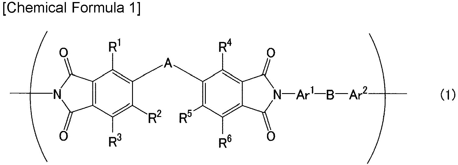

- According to one embodiment of the present invention, the separation functional layer includes a matrix and a filler dispersed in the matrix.
- According to one embodiment of the present invention, the thickness of the separation functional layer is 0.1 µm to 2.5 µm.
- According to one embodiment of the present invention, the separation membrane is used for separating water from a liquid mixture containing an alcohol and water.
- According to one embodiment of the present invention, when, in a state in which a liquid mixture composed of ethanol and water is in contact with one surface of the separation membrane, a space adjacent to an other surface of the separation membrane is decompressed, a flux of the water permeating through the separation membrane is 0.40 kg/m2/hr or more. A concentration of the ethanol in the liquid mixture is 50 vol% when measured with a temperature of the liquid mixture at 20°C, the liquid mixture in contact with the separation membrane has a temperature of 60°C, and the space adjacent to the other surface of the separation membrane is decompressed in such a manner that a pressure in the space is lower than an atmospheric pressure in a measurement environment by 100 kPa.
- According to one embodiment of the present invention, the separation membrane has a separation factor α of 20 or more for water with respect to ethanol. In a state in which a liquid mixture composed of ethanol and water is in contact with one surface of the separation membrane, the separation factor α is measured by decompressing a space adjacent to an other surface of the separation membrane. A concentration of the ethanol in the liquid mixture is 50 vol% when measured with a temperature of the liquid mixture at 20°C, the liquid mixture in contact with the separation membrane has a temperature of 60°C, and the space adjacent to the other surface of the separation membrane is decompressed in such a manner that a pressure in the space is lower than an atmospheric pressure in a measurement environment by 100 kPa.
- Hereinafter, the present invention will be described in detail. The following description is not intended to limit the present invention to specific embodiments.
- As shown in
FIG. 1 , aseparation membrane 10 of the present embodiment includes a separationfunctional layer 1, aninterlayer 2, and aporous support member 3 in this order in a stacking direction. The separationfunctional layer 1 allows, for example, water contained in a liquid mixture to permeate therethrough preferentially or selectively. Theinterlayer 2 is, for example, in direct contact with each of the separationfunctional layer 1 and theporous support member 3. - In the present embodiment, the
interlayer 2 has a thickness of 0.1 µm to 2.5 µm. The thickness of theinterlayer 2 is preferably 2.3 µm or less, more preferably 2.0 µm or less, still more preferably 1.5 µm or less, and particularly preferably 1.0 µm or less. The thickness of theinterlayer 2 may be 0.5 µm or more. The thickness of theinterlayer 2 can be determined by the following method, for example. First, a cross-section of theseparation membrane 10 is observed with a scanning electron microscope. Using an electron microscope image obtained, a distance between a pair of principal surfaces, of theinterlayer 2, that face each other is measured at a plurality of arbitrary points (at least three points). An average of the obtained values can be assumed as the thickness of theinterlayer 2. In the present description, the term "principal surface" means a surface, of theinterlayer 2, that has a largest area. - Furthermore, in the present embodiment, a total value T of the thickness of the
interlayer 2 and a thickness of the separationfunctional layer 1 is less than 4.0 µm. The thickness of the separationfunctional layer 1 is not particularly limited as long as the total value T is less than 4.0 µm. The thickness of the separationfunctional layer 1 is 0.1 µm to 2.5 µm, for example, and it is preferably 2.3 µm or less, more preferably 2.0 µm or less, still more preferably 1.8 µm or less, and particularly preferably 1.5 µm or less. The thickness of the separationfunctional layer 1 may be 0.5 µm or more. The thickness of the separationfunctional layer 1 can be determined by the method mentioned above for theinterlayer 2. - The total value T of the thickness of the
interlayer 2 and the thickness of the separationfunctional layer 1 is preferably 3.5 µm or less, more preferably 3.3 µm or less, still more preferably 3.0 µm or less, particularly preferably 2.8 µm or less, and especially preferably 2.5 µm or less. The lower limit of the total value T is not particularly limited and it is 0.5 µm, for example, and it is preferably 1.0 µm and more preferably 1.5 µm. - A ratio R of the thickness of the separation
functional layer 1 with respect to the thickness of theinterlayer 2 is not particularly limited and it is 10 or less, for example, and it is preferably 5.0 or less, more preferably 3.0 or less, still more preferably 2.0 or less, and particularly preferably 1.0 or less. The lower limit of the ratio R is not particularly limited, and it is 0.1, for example. It may be 0.3, 0.5, or 0.6 in some cases. - As for conventional separation membranes, it was common to adjust a thickness of an interlayer to be relatively large from the viewpoint of inhibiting sufficiently the occurrence of defects at the time of production. As far as the present inventors are aware, no separation membranes with an interlayer having a thickness adjusted to about 2.5 µm or less have been known until now.
- The separation
functional layer 1 has amatrix 4 and a filler 5, for example. The filler 5 is dispersed in thematrix 4 and is buried in thematrix 4. In the embodiment shown inFIG. 1 , all particles of the filler 5 are spaced apart from each other. The filler 5 may be condensed partially. The separationfunctional layer 1 may not include the filler 5. - Preferably, the
matrix 4 contains polyimide. As the polyimide contained in thematrix 4, polyimide (P) including a structural unit represented by formula (1) below can be mentioned, for example.
- In the formula (1), A is, for example, a linking group having a solubility parameter, in accordance with a Fedors method, of more than 5.0 (cal/cm3)1/2. In the present description, the "solubility parameter in accordance with a Fedors method" is also referred to as an SP value. The "solubility parameter in accordance with a Fedors method" can be calculated by the following formula. It should be noted that in this formula, δi is the SP value of an atom or atomic group of an i component. Δei is an evaporation energy of the atom or atomic group of the i component. Δvi is a molar volume of the atom or atomic group of the i component.

- The detail of the "solubility parameter in accordance with a Fedors method" is disclosed, for example, in "Polymer Engineering and Science" written by Robert F. Fedors, the year 1974, volume no. 14, the second issue, P. 147-154.
- When the SP value of A is more than 5.0 (cal/cm3)1/2, water tends to penetrate into the separation
functional layer 1 easily. The SP value of A is preferably 8.5 (cal/cm3)1/2 or more, more preferably 11.0 (cal/cm3)1/2 or more, and still more preferably 12.0 (cal/cm3)1/2 or more. The upper limit of the SP value of A is not particularly limited, and it may be 30.0 (cal/cm3)1/2, for example. Preferable examples of the SP value of A include 12.0 (cal/cm3)1/2 and 12.68 (cal/cm3)1/2. - A includes, for example, at least one selected from the group consisting of an oxygen atom, a nitrogen atom, a sulfur atom, and a silicon atom. Preferably, A includes at least one selected from the group consisting of an oxygen atom and a nitrogen atom. Particularly preferably, A includes an oxygen atom. A includes, for example, at least one functional group selected from the group consisting of an ether group, an ester group, a ketone group, a hydroxy group, an amide group, a thioether group, and a sulfonyl group. Preferably, A includes at least one selected from the group consisting of an ether group and an ester group.
- A may include another group, such as a hydrocarbon group, besides the above-mentioned functional groups. The number of carbon atoms that the hydrocarbon group has is not particularly limited, and it is 1 to 15, for example. The number of carbon atoms may be 1 to 3, or may be 6 to 15. The valence of the hydrocarbon group is not particularly limited, either. Preferably, the hydrocarbon group is a divalent hydrocarbon group. Examples of the divalent hydrocarbon group include a methylene group, an ethylene group, a propane-1,3-diyl group, a propane-2,2-diyl group, a butane-1,4-diyl group, a pentane-1,5-diyl group, a 2,2-dimethylpropane-1,3-diyl group, a 1,4-phenylene group, a 2,5-di-tert-butyl-1,4-phenylene group, a 1-methyl-1,1-ethanediylbis(1,4-phenylene) group, and a biphenyl-4,4'-diyl group. Furthermore, at least one hydrogen atom included in these hydrocarbon groups may be substituted by a halogen atom.
- A is a linking group represented by, for example, a general formula -O-R19-O- or a general formula -COO-R20-OOC-. As stated herein, R19 and R20 each are a divalent hydrocarbon group having 1 to 15 carbon atoms. As the divalent hydrocarbon group, the divalent hydrocarbon groups stated above can be mentioned.
- A may not include the above-mentioned functional groups. Examples of such A include an alkylene group. The number of carbon atoms that the alkylene group has is not particularly limited, and it may be 1 to 15, for example, and it may be 1 to 5. The alkylene group may be branched, but preferably it is linear. A part of hydrogen atoms included in the alkylene group may be substituted by a halogen atom. However, it is preferable that the alkylene group be an alkylene group without the substitution, that is, a linear or branched alkylene group.
- In the formula (1), the number of atoms constituting a bonding chain, among bonding chains that bond two phthalimide structures linked to each other by A, that is composed of a least number of atoms is 2 or more, for example, and it is preferably 4 or more, and more preferably 6 to 11. In the present description, the bonding chain composed of a least number of atoms is also referred to as a "shortest bonding chain". For example, in the case where A is an o-phenylene group, the number of atoms constituting a shortest bonding chain that bonds two phthalimide structures linked to each other by A is 2. In the case where A is a p-phenylene group, the number of atoms constituting a shortest bonding chain that bonds two phthalimide structures linked to each other by A is 4.
- A may be one of the linking
groups 1 to 26 shown in Tables 1 and 2 below. Tables 1 and 2 show the chemical structure, the SP value, and the number of atoms constituting a shortest bonding chain of each of the linkinggroups 1 to 26. A is preferably the linkinggroup 11 or the linking group 18, and particularly preferably the linking group 18. In the case where A is the linkinggroup 11 or the linking group 18, the polyimide (P) is easily dissolved in a polar organic solvent, such as N-methyl-2-pyrrolidone (NMP) and 1,3-dioxolane, and is easily adopted in a method desirable for manufacturing the separationfunctional layer 1.[Table 1] -A- SP value [(cal/cm3)1/2] The number of atoms constituting shortest bonding chain 1 -CF2- 6.66 1 2 -CHC(CH3)3- 7.52 1 3 -CH2- 8.56 1 4 -(CH2)5- 8.56 5 5 -O-CH2-C(CH3)2-CH2-O- 8.65 5 6 -O-(CH2)5-O- 9.23 7 7 -O-(CH2)4-O- 9.37 6 8 
9.51 6 9 
9.62 11 10 -O-CH2-O- 10.83 3 11 11.02 11 12 11.52 8 13 12.00 7 14 12.25 10 15 12.29 11 [Table 2] -A- SP value [(cal/cm3)1/2] The number of atoms constituting shortest bonding chain 16 
12.40 6 17 -SO2- 12.47 1 18 
12.68 6 19 
13.06 11 20 
13.55 8 21 -O- 14.51 1 22 -S- 16.79 1 23 
18.19 8 24 -CO- 19.60 1 25 
20.74 12 26 -CONH- 29.02 2 - In the formula (1), B is, for example, a linking group having an SP value more than 8.56 (cal/cm3)1/2. Water tends to penetrate into the separation
functional layer 1 easily when the SP value of the linking group B is more than 8.56 (cal/cm3)1/2. The SP value of B is preferably 9.0 (cal/cm3)1/2 or more, more preferably 11.0 (cal/cm3)1/2 or more, still more preferably 12.0 (cal/cm3)1/2 or more, and particularly preferably 14.0 (cal/cm3)1/2 or more. The upper limit of the SP value of B is not particularly limited, and it may be 30.0 (cal/cm3)1/2, for example. Preferable examples of the SP value of B include 14.0 (cal/cm3)1/2 and 14.51 (cal/cm3)1/2. - B includes, for example, at least one selected from the group consisting of an oxygen atom, a nitrogen atom, a sulfur atom, and a silicon atom. Preferably, B includes at least one selected from the group consisting of an oxygen atom and a nitrogen atom. Particularly preferably, B includes an oxygen atom. B includes, for example, at least one functional group selected from the group consisting of an ether group, an ester group, a ketone group, a hydroxy group, an amide group, a thioether group, and a sulfonyl group. Preferably, B includes an ether group.
- B may include another group, such as a hydrocarbon group, besides the above-mentioned functional groups. As the hydrocarbon group, the hydrocarbon groups stated above for A can be mentioned. B may be identical to or different from A.
- In the formula (1), the number of atoms constituting a bonding chain (a shortest bonding chain), among bonding chains that bond Ar1 and Ar2 linked to each other by B, that is composed of a least number of atoms is 1 or more, for example. The upper limit of the number of atoms constituting the shortest bonding chain is not particularly limited, and it is 12, for example. Preferably, the number of atoms constituting the shortest bonding chain is 1.
- B may be one of the linking groups 5 to 26 shown in the above-mentioned Tables 1 and 2. B is preferably the linking group 9, the linking group 16, or the linking
group 21, and particularly preferably the linkinggroup 21. - In the formula (1), R1 to R6 each are independently a hydrogen atom, a halogen atom, a hydroxy group, a sulfonic group, an alkoxy group having 1 to 30 carbon atoms, or a hydrocarbon group having 1 to 30 carbon atoms. Preferably, R1 to R6 each are a hydrogen atom. The alkoxy group or the hydrocarbon group as R1 to R6 may be either linear or branched. The number of carbon atoms that the alkoxy group or the hydrocarbon group has is preferably 1 to 20, more preferably 1 to 10, and particularly preferably 1 to 5. Examples of the alkoxy group include a methoxy group, an ethoxy group, and a propoxy group. Examples of the hydrocarbon group include a methyl group, an ethyl group, and a propyl group. At least one hydrogen atom included in the alkoxy group or the hydrocarbon group may be substituted by a halogen atom.
- R2 and R3 as well as R5 and R6 may be bond to each other to form a ring structure. The ring structure is a benzene ring, for example.
- In the formula (1), Ar1 and Ar2 each are a divalent aromatic group. The divalent aromatic group includes an aromatic ring. In the formula (1), it is preferable that a nitrogen atom in a phthalimide structure be bonded directly to the aromatic ring included in Ar1, or the aromatic ring included in Ar2. In the formula (1), B may be bonded directly to both of the aromatic ring included in Ar1 and the aromatic ring included in Ar2.
- In Ar1 and Ar2, it is preferable that the aromatic ring be composed of a carbon atom. It should be noted that the aromatic ring may be a heteroaromatic ring including a hetero atom such as an oxygen atom, a nitrogen atom, and a sulfur atom. The aromatic ring may be polycyclic, but preferably it is monocyclic. The number of carbon atoms that the aromatic ring has is not particularly limited, and it may be 4 to 14, for example, and it may be 6 to 10. Examples of the aromatic ring include a benzene ring, a naphthalene ring, an anthracene ring, a phenanthrene ring, a furan ring, a pyrrole ring, a pyridine ring, and a thiophene ring.
- In Ar1 and Ar2, the aromatic ring may or may not have a substituent. Examples of the substituent of the aromatic ring include a halogen atom, a hydroxy group, a sulfonic group, an alkoxy group having 1 to 30 carbon atoms, and a hydrocarbon group having 1 to 30 carbon atoms. As the alkoxy group and the hydrocarbon group, the alkoxy groups and the hydrocarbon groups stated above for R1 to R6 can be mentioned. In the case where the aromatic ring has a plurality of substituents, the substituents may be identical to or different from each other.
- Preferably, Ar1 and Ar2 each are a phenylene group that may have a substituent, or a naphthalenediyl group that may have a substituent. And Ar1 and Ar2 each may be represented by formula (2) below when Ar1 and Ar2 each are a phenylene group that may have a substituent.

- In the formula (2), R7 to R10 each are independently a hydrogen atom, a halogen atom, a hydroxy group, a sulfonic group, an alkoxy
group having 1to 30 carbon atoms, or a hydrocarbon group having 1 to 30 carbon atoms. As the alkoxy group and the hydrocarbon group, the alkoxy groups and the hydrocarbon groups stated above for R1 to R6 can be mentioned. Preferably, R7 to R10 each are a hydrogen atom. The formula (2) represents a p-phenylene structure. Polyimide having the p-phenylene structure is less bulky three-dimensionally than polyimide having an o-phenylene structure or an m-phenylene structure, and is suitable for enhancing the separation performance of the separation membrane. - The naphthalenediyl group, as Ar1 and Ar2, that may have a substituent has a naphthalene-2,6-diyl structure, a naphthalene-1,4-diyl structure, a naphthalene-1,5-diyl structure, or a naphthalene-1,8-diyl structure, for example. The naphthalenediyl group that may have a substituent is a naphthalene-2,6-diyl group, for example.
- Ar1 and Ar2 may be identical to or different from each other. For example, there may be a case in which Ar1 is a naphthalene-2,6-diyl group while Ar2 is a p-phenylene group.
- In the polyimide (P), the structural unit represented by the formula (1) is preferably a structural unit represented by formula (3) below.

- In the formula (3), A, B, and R1 to R6 are identical to those mentioned above for the formula (1). R11 to R18 each are independently a hydrogen atom, a halogen atom, a hydroxy group, a sulfonic group, an alkoxy group having 1 to 30 carbon atoms, and a hydrocarbon group having 1 to 30 carbon atoms. As the alkoxy group and the hydrocarbon group, the alkoxy groups and the hydrocarbon groups stated above for R1 to R6 can be mentioned. R11 to R18 each are preferably a hydrogen atom.
- A content of the structural unit represented by the formula (1) in the polyimide (P) is 50 mol% or more, for example, and it is preferably 60 mol% or more, more preferably 70 mol% or more, still more preferably 80 mol% or more, and particularly preferably 90 mol% or more. The content of the structural unit represented by the formula (1) may be 100 mol%.
- The structural unit represented by the formula (1) can be obtained by a reaction between tetracarboxylic dianhydride (C) represented by formula (4) below and a diamine compound (D) represented by formula (5) below. In the formula (4), A as well as R1 to R6 are identical to those in the formula (1). In the formula (5), B, Ar1, and Ar2 are identical to those in the formula (1).


[Chemical Formula 7] H2N-Ar1-B-Ar2-NH2 (5)
- The polyimide (P) may include a structural unit derived from an other tetracarboxylic dianhydride that is different from the tetracarboxylic dianhydride (C). The other tetracarboxylic dianhydride is not particularly limited, and a known tetracarboxylic dianhydride can be used. Examples of the other tetracarboxylic dianhydride include pyromellitic dianhydride, and 4,4'-(hexafluoroisopropylidene)diphthalic anhydride.
- In the polyimide (P), a ratio P1 of a structural unit(s) derived from the tetracarboxylic dianhydride (C) with respect to structural units derived from all the tetracarboxylic dianhydrides is 50 mol% or more, for example, and it is preferably 70 mol% or more, and more preferably 90 mol% or more. The ratio P1 may be 100 mol%.
- The polyimide (P) may include a structural unit derived from an other diamine compound that is different from the diamine compound (D). The other diamine compound is not particularly limited and a known diamine compound can be used. Examples of the other diamine compound include phenylenediamine, diaminobenzoic acid, diaminobiphenyl, and diaminodiphenylmethane. For example, the polyimide (P) may include a structural unit derived from diaminobenzoic acid (such as 3,5-diaminobenzoic acid). The polyimide (P) including the structural unit derived from diaminobenzoic acid is suitable for increasing a flux of the water permeating through the
separation membrane 10. - In the polyimide (P), a ratio P2 of a structural unit(s) derived from the diamine compound (D) with respect to structural units derived from all the diamine compounds is 50 mol% or more, for example, and it is preferably 70 mol% or more, and more preferably 90 mol% or more. The ratio P2 may be 100 mol%.
- The polyimide (P) can be produced by the following method, for example. First, the diamine compound (D) is dissolved in a solvent to obtain a solution. Examples of the solvent include a polar organic solvent such as N-methyl-2-pyrrolidone (NMP) and 1,3-dioxolane. Next, the tetracarboxylic dianhydride (C) is added gradually to the obtained solution. This makes the tetracarboxylic dianhydride (C) and the diamine compound (D) react with each other to form polyamide acid. The addition of the tetracarboxylic dianhydride (C) is carried out under the conditions, for example, that the solution is being stirred for 3 to 20 hours at a temperature equal to or lower than a room temperature (25°C).
- Subsequently, the polyamide acid is imidized to obtain the polyimide (P). Examples of the imidization method include a chemical imidization method and a thermal imidization method. The chemical imidization method is a method for imidizing polyamide acid using a dehydration condensation agent. The chemical imidization method may be carried out under a room temperature condition or a heat condition. Examples of the dehydration condensation agent include acetic anhydride, pyridine, and triethylamine. The thermal imidization method is a method for imidizing polyamide acid by a heat treatment. The heat treatment is carried out at a temperature of 180°C or higher, for example.
- A content of the polyimide (P) in the
matrix 4 is 50 wt% or more, for example, and it is preferably 60 wt% or more, more preferably 70 wt% or more, still more preferably 80 wt% or more, and particularly preferably 90 wt% or more. Thematrix 4 is composed substantially of the polyimide (P), for example. - A content of the
matrix 4 in the separationfunctional layer 1 is 70 wt% or more, for example. The upper limit of the content of thematrix 4 is not particularly limited, and it may be 99 wt% or 95 wt%. - The filler 5 has hydrophilicity and is porous, for example. The filler 5 as just mentioned is suitable for increasing the flux of the water permeating through the
separation membrane 10 without deteriorating the separation performance of theseparation membrane 10 significantly. The filler 5 includes, for example, at least one selected from the group consisting of zeolite and a metal organic framework (MOF). From the viewpoint of durability against water, it is preferable that the filler 5 include the metal organic framework. As the zeolite, molecular sieves 3A, 4A, 5A, and 13X can be mentioned, for example. - The metal organic framework is also referred to as a porous coordination polymer (PCP). The metal organic framework includes a metal ion and an organic ligand, for example. Examples of the metal ion include a Co ion, an Ni ion, a Zn ion, an Mg ion, a Zr ion, and a Cu ion. The organic ligand may not have a polar group, but preferably it has a polar group. Examples of the polar group include an aldehyde group, an amino group, an amide group, a hydroxy group, a carboxyl group, and a nitro group. The organic ligand includes an aromatic ring, for example. Examples of the aromatic ring included in the organic ligand include a benzene ring and an imidazole ring. Examples of the organic ligand include 2-hydroxymethylimidazole, 2-formylimidazole, terephthalic acid, 2-hydroxyterephthalic acid, 2,5-dihydroxyterephthalic acid, and 2-aminoterephthalic acid.
- Examples of the metal organic framework include ZIF-90, ZIF-91, UiO-66, UiO-66-NH2, UiO-66-OH, UiO-66-NO2, UiO-66-COOH, HKUST-1, and MOF-74 (M = Co, Ni, Zn, Mg, etc.). From the viewpoint of increasing the flux of the water permeating through the
separation membrane 10, it is preferable that the metal organic framework include at least one selected from the group consisting of ZIF-90, UiO-66-NH2, UiO-66-OH, UiO-66-NO2, UiO-66-COOH, and MOF-74 (Ni). More preferably, the metal organic framework includes UiO-66-COOH. - As the filler 5, a filler that can adsorb water is suitable. In particular, a filler that adsorbs water better than it adsorbs ethanol is suitable as the filler 5. A ratio R1 of an adsorption amount Q2 of water adsorbed by the filler 5 under water vapor at 25°C and 3.2 kPa with respect to an adsorption amount Q1 of ethanol adsorbed by the filler 5 under an ethanol atmosphere at 25°C and 7.4 kPa is 2.0 or more, for example, and is preferably 3.0 or more. The upper limit of the ratio R1 is not particularly limited, and it is 5.0, for example. The ratio R1 is used as an index of hydrophilicity of the filler 5 in some cases. In the present description, the term "adsorption amount" means a value obtained by converting a volume of a gas that 1 g of the filler 5 has adsorbed into a volume of the gas in a standard state (298 K, 1 atm).
- The adsorption amount Q1 of ethanol adsorbed by the filler 5 can be determined by the following method. First, this filler 5 is pretreated by being heated under a decompressed atmosphere. The pretreatment may be carried out under a vacuum atmosphere. The pretreatment is carried out at a temperature of 100°C or higher, for example. The duration of the pretreatment is not particularly limited, and it is 1 hour or longer, for example. Next, the filler 5 is placed in a known vapor adsorption amount measuring apparatus such as BELSORP-maxII available from MicrotracBEL Corp. Next, gaseous ethanol is introduced into the measuring apparatus at a measurement temperature of 25°C. The gaseous ethanol introduced is adsorbed by the filler 5. The gaseous ethanol is introduced until the pressure of the ethanol in the measuring apparatus reaches 7.4 kPa. The pressure of 7.4 kPa is equivalent to an equilibrium vapor pressure (a saturation vapor pressure) of ethanol at 25°C. The adsorption of the ethanol by the filler 5 is confirmed to have reached a state of equilibrium, and then the adsorption amount of the ethanol adsorbed by the filler 5 is determined. The fact that the adsorption of the ethanol by the filler 5 has reached a state of equilibrium can be confirmed by a change in the pressure of the ethanol inside the measuring apparatus. For example, when the change in the pressure of the ethanol inside the measuring apparatus is 40 Pa or less for 500 seconds, the adsorption of the ethanol by the filler 5 can be considered to have reached a state of equilibrium. The adsorption amount of the ethanol that is determined by the above-mentioned method can be assumed as the adsorption amount Q1.
- The adsorption amount Q2 of water adsorbed by the filler 5 can be determined by the following method. First, the filler 5 is subject to the pretreatment mentioned above. The filler 5 is placed in a vapor adsorption amount measuring apparatus. Next, water vapor is introduced into the measuring apparatus at a measurement temperature of 25°C. The water vapor is introduced until the pressure of the water vapor in the measuring apparatus reaches 3.2 kPa. The pressure of 3.2 kPa is equivalent to an equilibrium vapor pressure of water at 25°C. The adsorption of the water by the filler 5 is confirmed to have reached a state of equilibrium, and then the adsorption amount of the water adsorbed by the filler 5 is determined. The determined adsorption amount of the water can be assumed as the adsorption amount Q2.
- The adsorption amount Q1 of ethanol adsorbed by the filler 5 is 200 cm3/g or less, for example. The lower limit of the adsorption amount Q1 is not particularly limited, and it may be 90 cm3/g or 100 cm3/g. The adsorption amount Q2 of water adsorbed by the filler 5 is 300 cm3/g or more, for example, and it may be 350 cm3/g or more, 450 cm3/g or more, 500 cm3/g or more, or 550 cm3/g or more in some cases. The upper limit of the adsorption amount Q2 is not particularly limited, and it is 800 cm3/g, for example.
- The filler 5 may be a filler in which a ratio R2 of a BET (Brunauer-Emmett-Teller) specific surface area S2 obtained by water vapor adsorption with respect to a BET specific surface area S1 obtained by nitrogen gas adsorption is 0.005 or more. The ratio R2 is used as an index of hydrophilicity of the filler 5 in some cases. In the filler 5, the ratio R2 is 0.01 or more, for example, and it is preferably 0.1 or more, more preferably 0.2 or more, and still more preferably 0.3 or more. The ratio R2 may be 25 or less, 10 or less, 1.0 or less, or 0.6 or less.
- In the filler 5, the BET specific surface area S1 obtained by nitrogen gas adsorption is 1500 m2/g or less, for example, and it is preferably 1000 m2/g or less. It may be 900 m2/g or less in some cases. The specific surface area S1 may be 30 m2/g or more, or 400 m2/g or more. In the filler 5, the BET specific surface area S2 obtained by water vapor adsorption is 10 m2/g or more, for example, and it is preferably 100 m2/g or more, and more preferably 150 m2/g or more. It may be 200 m2/g or more in some cases. The specific surface area S2 may be 1000 m2/g or less, 600 m2/g or less, or 400 m2/g or less.
- The filler 5 has a shape that is not particularly limited, and it is a particulate shape, for example. In the present description, the "particulate" is a shape such as a spherical shape, an elliptical shape, a flaky shape, and a fibrous shape. The filler 5 has an average particle diameter that is not particularly limited, and it is 5 nm to 10000 nm, for example. The average particle diameter of the filler 5 can be determined by the following method, for example. First, a cross section of the separation
functional layer 1 is observed with a transmission electron microscope. On an electron microscope image obtained, an area of a particular particle of the filler 5 is calculated by image processing. A diameter of a circle having an area equal to the calculated area is assumed as a diameter of that particular particle (a diameter of a particle) of the filler 5. A particle diameter of each of an arbitrary number (at least 50) of particles of the filler 5 is calculated. An average of the calculated values is assumed as the average particle diameter of the filler 5. - A content of the filler 5 in the separation
functional layer 1 may be 1 wt% or more, 5 wt% or more, 10 wt% or more, 15 wt% or more, or 20 wt% or more, for example. The content of the filler 5 in the separationfunctional layer 1 may be 30 wt% or less. - The
interlayer 2 contains a polymer compound (E), for example. In the present embodiment, it is preferable that a distance Ra between a Hansen solubility parameter of the polymer compound (E) and a Hansen solubility parameter of H2O be less than 19 MPa1/2. Theinterlayer 2 containing the polymer compound (E) as just mentioned is suitable for inhibiting the flux of the water permeating through theseparation membrane 10 from decreasing. Furthermore, the polymer compound (E) is suitable for inhibiting the occurrence of defects in theinterlayer 2 at the time of producing theinterlayer 2 while adjusting the thickness of theinterlayer 2 to 2.5 µm or less. Theinterlayer 2 containing the polymer compound (E) also has an advantage that the separationfunctional layer 1 containing polyimide and having a thickness of about 2.5 µm or less can be formed easily on a surface of theinterlayer 2. It should be noted that the above-mentioned distance Ra may be 19 MPa1/2 or more depending on a composition of the separationfunctional layer 1, the use of the separation membrane, etc. - That is, the present invention provides, from another aspect, the
separation membrane 10 including the separationfunctional layer 1, theinterlayer 2, and theporous support member 3 in this order in a stacking direction, wherein - the
interlayer 2 contains the polymer compound (E), and - the distance Ra between the Hansen solubility parameter of the polymer compound (E) and the Hansen solubility parameter of H2O is less than 19 MPa1/2.
- The Hansen solubility parameter is a parameter obtained by dividing a solubility parameter introduced by Hildebrand into three components of a dispersion term δD, a polar term δP, and a hydrogen bond term δH. The details of the Hansen solubility parameter are disclosed in "Hansen Solubility Parameters; A Users Handbook" (CRC Press, 2007). The Hansen solubility parameter can be calculated by, for example, using a known software such as HSPiP.
- The distance Ra between the Hansen solubility parameter of the polymer compound (E) and the Hansen solubility parameter of H2O can be calculated by formula (i) below. In the formula (i), δD1, δP1, and δH1 are, respectively, a dispersion term (MPa1/2), a polar term (MPa1/2), and a hydrogen bond term (MPa1/2) of the polymer compound (E). δD2, δP2, and δH2 are respectively a dispersion term (18.1 MPa1/2), a polar term (17.1 MPa1/2), and a hydrogen bond term (16.9 MPa1/2) of H2O.

- The distance Ra between the Hansen solubility parameter of the polymer compound (E) and the Hansen solubility parameter of H2O is preferably 18 MPa1/2 or less, more preferably 17 MPa1/2 or less, still more preferably 16 MPa1/2 or less, and particularly preferably 15 MPa1/2 or less. From the viewpoint of inhibiting the polymer compound (E) from swelling with water when the water permeates through the
separation membrane 10, the lower limit of the distance Ra is preferably 5 MPa1/2, and more preferably 8 MPa1/2. It may be 10 MPa1/2 or 13 MPa1/2 in some cases. - The polymer compound (E) contains, for example, at least one selected from the group consisting of polyether block amide, polyvinyl alcohol (PVA), polyether, and polyurethane. As the polyether, polyethylene glycol (PEG) can be mentioned, for example. From the viewpoint of allowing the separation
functional layer 1 containing polyimide to be formed on a surface of theinterlayer 2 easily, it is preferable that the polymer compound (E) include the polyether block amide. However, the polymer compound (E) may include silicone polymer, such as dimethylpolysiloxane, in some cases. - The polyether block amide is a block copolymer containing a polyether block PE and a polyamide block PA. The polyether block amide is represented by formula (6) below, for example.

- In the formula (6), R21 is a divalent hydrocarbon group having 1 to 15 carbon atoms. As for R21, the number of carbon atoms that the divalent hydrocarbon group has may be 1 to 10 or 1 to 5. As for R21, the divalent hydrocarbon group is preferably an alkylene group that is linear or branched. Specific examples of R21 are an ethylene group and a butane-1,4-diyl group. R22 is a divalent hydrocarbon group having 1 to 20 carbon atoms. As for R22, the number of carbon atoms that the divalent hydrocarbon group has may be 3 to 18, or 3 to 15. As for R22, the divalent hydrocarbon group is preferably an alkylene group that is linear or branched. Specific examples of R22 are a pentane-1,5-diyl group and an undecane-1,11-diyl group.
- In the formula (6), a ratio (x:y) between x and y is 1:9 to 9:1, for example, and it is preferably 5:5 to 9:1, and more preferably 6:4 to 8:2. The letter n refers to an integer of 1 or more.
- As specific examples of the polyether block amide, Pebax (registered trademark) 2533 and 1657 available from Arkema can be mentioned.
- Table 3 below shows specific examples 1 to 5 of the polymer compound (E). Table 3 also shows the Hansen solubility parameter and the above-mentioned distance Ra of each of the specific examples 1 to 5.
[Table 3] Polymer compound (E) Structure δD (MPa1/2) δP (MPa1/2) δH (MPa1/2) Distance Ra (MPa1/2) 1 Pebax 2533 
16.6 5.8 5.3 16.5 2 Pebax 1657 
17.5 9.0 7.6 12.4 3 PVA 
20.0 12.6 22.4 8.1 4 PEG 
17.2 9.0 7.3 12.7 5 Silicone (YSR3200) 
14.4 4.5 4.3 19.3 - The
interlayer 2 may contain the polymer compound (E), particularly the polyether block amide, as a main component, and a content thereof is 50 wt% or more, for example, and it is preferably 60 wt% or more, more preferably 70 wt% or more, still more preferably 80 wt% or more, and particularly preferably 90 wt% or more. Preferably, theinterlayer 2 is composed substantially of the polymer compounds (E). - The
porous support member 3 is not particularly limited as long as it can support the separationfunctional layer 1 and theinterlayer 2. Examples of theporous support member 3 include: a nonwoven fabric; porous polytetrafluoroethylene; aromatic polyamide fiber; a porous metal; a sintered metal; porous ceramic; porous polyester; porous nylon; activated carbon fiber; latex; silicone; silicone rubber; a permeable (porous) polymer including at least one selected from the group consisting of polyvinyl fluoride, polyvinylidene fluoride, polyurethane, polypropylene, polyethylene, polycarbonate, polysulfone, polyether ether ketone, polyacrylonitrile, polyimide, and polyphenylene oxide; a metallic foam having an open cell or a closed cell; a polymer foam having an open cell or a closed cell; silica; porous glass; and a mesh screen. Theporous support member 3 may be a combination of two or more of these materials. - The
porous support member 3 has an average pore diameter of 0.01 to 0.4 µm, for example. Theporous support member 3 has a thickness that is not particularly limited. It is 10 µm or more, for example, and it is preferably 20 µm or more, and more preferably 50 µm or more. The thickness of theporous support member 3 is 300 µm or less, for example, and it is preferably 200 µm or less, and more preferably 75 µm or less. - The
separation membrane 10 can be produced by the following method, for example. First, a coating liquid containing the polymer compound (E) is prepared. Examples of a solvent of the coating liquid include an organic solvent such as 2-propanol (IPA). A concentration of the polymer compound (E) in the coating liquid is not particularly limited, and it is 1 wt% to 10 wt%, for example, and it is preferably 3 wt% to 7wt%. In order to dissolve the polymer compound (E) in the solvent of the coating liquid, the solvent may be heated beforehand. The temperature at which the solvent is heated is not particularly limited as long as it is equal to or lower than a boiling point of the solvent, and it is 30°C to 80°C, for example. Next, the coating liquid is applied onto theporous support member 3 to obtain a coating. The coating is dried to form theinterlayer 2. The thickness of theinterlayer 2 can be adjusted by the concentration of the polymer compound (E) in the coating liquid and a thickness of the coating. - Next, a coating liquid containing the filler 5 and a material of the
matrix 4 is prepared. As a solvent of the coating liquid, an organic solvent, such as 1,3-dioxolane, can be used. The coating liquid may be subject to ultrasonication in order to enhance the dispersibility of the filler 5 in the coating liquid. Next, the coating liquid is applied onto theinterlayer 2 to obtain a coating. The coating is dried to form the separationfunctional layer 1. Thereby, theseparation membrane 10 can be produced. - In the case where the
matrix 4 contains polyimide, the material of thematrix 4 contained in the coating liquid may be polyamide acid. In this case, the separationfunctional layer 1 can be formed by imidizing the polyamide acid after applying the coating liquid onto theinterlayer 2. - In order to form a thin separation functional layer, it can be considered to adjust a viscosity of a coating liquid for forming the separation functional layer to be relatively low, for example, to 10 mPa•s or less. A coating liquid including a filler tends to have a low viscosity. In the case where a coating liquid having a low viscosity is applied directly onto a porous support member, this coating liquid enters into the porous support member easily. The entry of the coating liquid into the porous support member makes it difficult for a coating to be formed uniformly on a surface of the porous support member, and defects tend to occur in the obtained separation functional layer. In addition, defects also tend to occur in the separation functional layer when a surface of the porous support member has a defect and a coating liquid for forming the separation functional layer is applied directly onto this surface.
- In the present embodiment, the coating liquid for forming the separation
functional layer 1 is applied not onto theporous support member 3 but onto theinterlayer 2, and thus the coating liquid is unlikely to enter into theporous support member 3. Therefore, even in the cases where the coating liquid has a relatively low viscosity and where a surface of theporous support member 3 has a defect, it is possible to inhibit sufficiently defects from occurring in the separationfunctional layer 1. For example, in the present embodiment, the number of the defects in the separationfunctional layer 1 per 1000 cm2 of a surface of the separationfunctional layer 1 is 10 or less, for example, and it is preferably five or less, more preferably two or less, and still more preferably zero. - In the
separation membrane 10 of the present embodiment, the thickness of theinterlayer 2 as well as the total value T of the thickness of theinterlayer 2 and the thickness of the separationfunctional layer 1 are adjusted properly. Thereby, the flux of the permeation fluid permeating through theseparation membrane 10 is inhibited from decreasing. For example, when, in a state in which a liquid mixture composed of ethanol and water is in contact with one surface of theseparation membrane 10, a space adjacent to an other surface of theseparation membrane 10 is decompressed, a flux F of the water permeating through theseparation membrane 10 is 0.30 kg/m2/hr or more, for example, and it is preferably 0.35 kg/m2/hr or more, more preferably 0.40 kg/m2/hr or more, still more preferably 0.45 kg/m2/hr or more, and particularly preferably 0.50 kg/m2/hr or more. The upper limit of the flux F of the water is not particularly limited, and it is 1.00 kg/m2/hr, for example. - Specifically, the flux F of the water can be measured by the following method. First, in a state in which a liquid mixture composed of ethanol and water is in contact with one surface (a
principal surface 11, on a side of the separation functional layer, of theseparation membrane 10, for example) of theseparation membrane 10, a space adjacent to an other surface (aprincipal surface 12, on a side of the porous support member, of theseparation membrane 10, for example) of theseparation membrane 10 is decompressed. Thereby, a permeation fluid that has permeated through theseparation membrane 10 can be obtained. In the above-mentioned procedure, a concentration of the ethanol in the liquid mixture is 50 vol% (44 wt%) when measured with a temperature of the liquid mixture at 20°C. The liquid mixture in contact with theseparation membrane 10 has a temperature of 60°C. The space adjacent to the other surface of theseparation membrane 10 is decompressed in such a manner that a pressure in the space is lower than an atmospheric pressure in a measurement environment by 100 kPa. Next, a weight of the permeation fluid and a weight ratio of the water in the permeation fluid are measured. The flux F of the water can be determined based on the obtained results. - Under the above-mentioned measurement conditions of the flux F of the water, a separation factor α that the
separation membrane 10 has for water with respect to ethanol is 20 or more, for example, and it is preferably 40 or more, and more preferably 45 or more. It may be 50 or more, 60 or more, or 65 or more in some cases. The upper limit of the separation factor α is not particularly limited, and it is 500, for example. Theseparation membrane 10 having the separation factor α that is 20 or more is sufficiently suitable to be used for separating water from a liquid mixture containing an alcohol and water. - The separation factor α can be calculated by the following formula. It should be noted that in the following formula, XA and XB are respectively a volume ratio of the water and a volume ratio of the alcohol in the liquid mixture. YA and YB are respectively the volume ratio of the water and the volume ratio of the alcohol in the permeation fluid that has permeated through the
separation membrane 10.
- The
separation membrane 10 of the present embodiment is used for, for example, separating water from a liquid mixture containing an alcohol and water. In this use, the flux of the water permeating through theseparation membrane 10 tends to be high. However, the use of theseparation membrane 10 is not limited to the above-mentioned use of separating water from a liquid mixture. - As shown in
FIG. 2 , amembrane separation device 100 of the present embodiment is provided with theseparation membrane 10 and atank 20. Thetank 20 is provided with afirst room 21 and asecond room 22. Theseparation membrane 10 is disposed in thetank 20. In thetank 20, theseparation membrane 10 separates thefirst room 21 from thesecond room 22. Thetank 20 has a pair of wall surfaces, and theseparation membrane 10 extends from one of them to the other. - The
first room 21 has aninlet 21a and anoutlet 21b. Thesecond room 22 has anoutlet 22a. Theinlet 21a, theoutlet 21b, and theoutlet 22a each are an opening formed in the wall surfaces of thetank 20, for example. - Membrane separation using the
membrane separation device 100 is carried out by the following method, for example. First, aliquid mixture 30 containing an alcohol and water is supplied into thefirst room 21 via theinlet 21a. This makes it possible to bring theliquid mixture 30 into contact with one surface of theseparation membrane 10. The alcohol contained in theliquid mixture 30 is, for example, a lower alcohol that exhibits azeotropy with water. The alcohol is preferably ethanol, and it may be isopropyl alcohol (IPA). A concentration of the alcohol in theliquid mixture 30 is 10 wt% or more, for example, and it is preferably 20 wt% or more. Theseparation membrane 10 is particularly suitable for separating the water from theliquid mixture 30 containing the alcohol at a moderate concentration (20 wt% to 80 wt%, particularly 30 wt% to 70 wt%). It should be noted that the concentration of the alcohol in theliquid mixture 30 may be 80 wt% or more. Theliquid mixture 30 may be composed substantially of the alcohol and water. A temperature of theliquid mixture 30 may be higher than a boiling point of the alcohol to be used. Preferably, the temperature is lower than the boiling point of the alcohol. The temperature of theliquid mixture 30 is 25°C or higher, for example, and it is preferably 40°C or higher, and more preferably 60°C or higher. The temperature of theliquid mixture 30 may be 75°C or lower. - Next, in a state in which the
liquid mixture 30 is in contact with one surface of theseparation membrane 10, a space adjacent to an other surface of theseparation membrane 10 is decompressed. Specifically, an inside of thesecond room 22 is decompressed via theoutlet 22a. Themembrane separation device 100 may be further provided with a pump (not shown) for decompressing the inside of thesecond room 22. Thesecond room 22 is decompressed in such a manner that a space in thesecond room 22 has a pressure lower than an atmospheric pressure in a measurement environment by 10 kPa or more, for example, and preferably by 50 kPa or more, and more preferably by 100 kPa or more. - Decompressing the inside of the
second room 22 makes it possible to obtain, on a side of the other surface of theseparation membrane 10, apermeation fluid 35 having a content of the water higher than a content of the water in theliquid mixture 30. That is, thepermeation fluid 35 is supplied into thesecond room 22. Thepermeation fluid 35 contains the water as a main component, for example. Thepermeation fluid 35 may contain a small amount of the alcohol besides the water. Thepermeation fluid 35 may be a gas or a liquid. Thepermeation fluid 35 is discharged to an outside of thetank 20 via theoutlet 22a. - The concentration of the alcohol in the
liquid mixture 30 increases gradually from theinlet 21a toward theoutlet 21b of thefirst room 21. The liquid mixture 30 (a concentrated fluid 36) processed in thefirst room 21 is discharged to the outside of thetank 20 via theoutlet 21b. - The
membrane separation device 100 of the present embodiment is used preferably for a pervaporation method. Themembrane separation device 100 may be used for other membrane separation methods such as a vapor permeation method. That is, a mixture gas containing a gaseous alcohol and gaseous water may be used instead of theliquid mixture 30 in the membrane separation method mentioned above. Themembrane separation device 100 of the present embodiment is suitable for a flow-type (continuous-type) membrane separation method. Themembrane separation device 100 of the present embodiment may be used for a batch-type membrane separation method. - As shown in
FIG. 3 , amembrane separation device 110 of the present embodiment is provided with acentral tube 41 and a laminate 42. The laminate 42 includes theseparation membrane 10. Themembrane separation device 110 is a spiral membrane element. - The
central tube 41 has a cylindrical shape. Thecentral tube 41 has a surface with a plurality of pores formed therein to allow thepermeation fluid 35 to flow into thecentral tube 41. Examples of a material of thecentral tube 41 include: a resin such as an acrylonitrile-butadiene-styrene copolymer (an ABS resin), a polyphenylene ether resin (a PPE resin), and a polysulfone resin (a PSF resin); and a metal such as stainless steel and titanium. Thecentral tube 41 has an inner diameter in a range of 20 to 100 mm, for example. - The laminate 42 further includes a supply-side
flow passage material 43 and a permeation-sideflow passage material 44 besides theseparation membrane 10. The laminate 42 is wound around a circumference of thecentral tube 41. Themembrane separation device 110 may be further provided with an exterior material (not shown). - As the supply-side
flow passage material 43 and the permeation-sideflow passage material 44, a resin net composed of polyphenylene sulfide (PPS) or an ethylene-chlorotrifluoroethylene copolymer (ECTFE) can be used, for example. - Membrane separation using the
membrane separation device 110 is carried out by the following method, for example. First, theliquid mixture 30 is supplied into an end of thewound laminate 42. An inner space of thecentral tube 41 is decompressed. Thereby, thepermeation fluid 35 that has permeated through theseparation membrane 10 of the laminate 42 moves into thecentral tube 41. Thepermeation fluid 35 is discharged to an outside via thecentral tube 41. The liquid mixture 30 (the concentrated fluid 36) processed by themembrane separation device 110 is discharged to the outside from an other end of thewound laminate 42. Thereby, the water can be separated from theliquid mixture 30. - Hereinafter, the present invention will be described in detail by way of examples and comparative examples. It should be noted that the present invention is not limited to these examples.
- First, polyether block amide (Pebax (registered trademark) 2533 available from Arkema) was dissolved in IPA at 80°C to prepare a coating liquid. A concentration of the polyether block amide in the coating liquid was 3 wt%. Next, the coating liquid was applied onto a porous support member to obtain a coating. As the porous support member, a UF membrane (ultrafiltration membrane) RS-50 (a laminate of a PVDF porous layer and a PET nonwoven fabric) available from Nitto Denko Corporation was used. The coating was formed on the PVDF porous layer of the RS-50. The application of the coating liquid was carried out using an applicator with a gap of 155 µm. Next, the coating was dried to form an interlayer with a thickness of 0.5 µm.
- Next, as tetracarboxylic dianhydride, bis(1,3-dioxo-1,3-dihydroisobenzofuran-5-carboxylic acid) ethylene (a compound represented by the formula (4) where A was the linking group 18 as well as R1 to R6 each were a hydrogen atom) was prepared. As diamine compounds, 4,4'-diaminodiphenyl ether (a compound represented by the formula (5) where B was the linking
group 21 as well as Ar1 and Ar2 each were a p-phenylene group), and 3,5-diaminobenzoic acid were prepared. Next, the diamine compounds were dissolved in N-methyl-2-pyrrolidone to obtain a solution. The tetracarboxylic dianhydride was added to the obtained solution under a room temperature condition to obtain polyamide acid. Next, the polyamide acid was chemically imidized using triethylamine and acetic anhydride to obtain polyimide. The chemical imidization was carried out in N-methyl-2-pyrrolidone under a temperature condition of 60°C. In the polyimide, a ratio of structural units derived from the 3,5-diaminobenzoic acid with respect to structural units derived from all the diamine compounds was 10 mol%. - Next, the polyimide was dissolved in 1,3-dioxolane to obtain a solution. Next, the polyimide solution was added to a dispersion containing molecular sieve 4A (Zeoal4A (with a particle diameter of 300 nm) available from Nakamura Choukou Co., Ltd.), and these were mixed. The obtained coating liquid was applied onto the interlayer to obtain a coating. Next, the coating was dried to form a separation functional layer with a thickness of 1.25 µm. A content of the polyimide in the separation functional layer was 80 wt%, and a content of the molecular sieve 4A was 20 wt%. Thereby, a separation membrane of Example 1 was obtained.
- Separation membranes of Examples 2 to 5 and 8 to 11 were obtained in the same manner as in Example 1, except that the thickness of the separation functional layer and the thickness of the interlayer were changed to the values shown in Table 4. The thickness of the interlayer was adjusted depending on the concentration of the polyether block amide in the coating liquid. The thickness of the separation functional layer was adjusted depending on a solid content concentration of the coating liquid.
- Separation membranes of Examples 6 and 12 were obtained in the same manner as in Example 1, except that Pebax (registered trademark) 1657 available from Arkema was used as the polyether block amide, and the thickness of the separation functional layer and the thickness of the interlayer were changed to the values shown in Table 4.
- A separation membrane of Example 7 was obtained in the same manner as in Example 1, except that the interlayer was omitted and the thickness of the separation functional layer was changed to the value shown in Table 4.
- First, a coating liquid containing silicone polymer was prepared. A distance Ra between a Hansen solubility parameter of the silicone polymer and a Hansen solubility parameter of H2O was 19 MPa1/2 or more. A content of the silicone polymer in the coating liquid was 2 wt%. Next, the coating liquid was applied onto a porous support member to obtain a coating. As the porous support member, a UF membrane (ultrafiltration membrane) RS-50 (a laminate of a PVDF porous layer and a PET nonwoven fabric) available from Nitto Denko Corporation was used. The coating was formed on the PVDF porous layer of the RS-50. The application of the coating liquid was carried out using an applicator with a gap of 130 µm. Next, the coating was dried to form an interlayer with a thickness of 1.8 µm.
- Subsequently, it was attempted to form a separation functional layer with a thickness of 0.5 µm on the interlayer in the same manner as in Example 1, but a lot of defects occurred in the obtained layer (20 or more defects per 1000 cm2 of a surface thereof) and a separation membrane was failed to be obtained.
- On each of the separation membranes of Examples 1 to 12, the number of defects in the separation functional layer was confirmed by the following method. First, a coloring material was dissolved in ethanol to produce a coloring liquid. This coloring liquid was applied onto the separation functional layer. Here, the coloring liquid entered into the separation functional layer at locations at which defects (pinholes) were present and colored such locations of the separation functional layer. Next, a surface of the separation functional layer was washed with ethanol. The number of the locations (colored locations) at which the coloring liquid entered into the separation functional layer was confirmed visually. Thereby, the number of the defects in the separation functional layer per 1000 cm2 of the surface of the separation functional layer was determined.
- On each of the separation membranes of Examples 1 to 12, the flux F of the water permeating through the separation membrane and the separation factor α were measured by the following method. First, the separation membrane was placed in a metal cell, and the metal cell was sealed with an O-ring so that no leakage occurred. Next, 250 mL of a liquid mixture was injected into the metal cell in such a manner that the liquid mixture was in contact with a principal surface, on a side of the separation functional layer, of the separation membrane. The liquid mixture was composed substantially of ethanol and water. A concentration of the ethanol in the liquid mixture was 50 vol% when measured with a temperature of the liquid mixture at 20°C. Next, the metal cell was heated to 60°C in a water bath. The temperature of the liquid mixture in the metal cell was confirmed to be 60°C, and then a space, in the metal cell, that is adjacent to a principal surface, on a side of the porous support member, of the separation membrane was decompressed. This space was decompressed in such a manner that a pressure in the space was lower than an atmospheric pressure in a measurement environment by 100 kPa. Thereby, a gaseous permeation fluid was obtained. The gaseous permeation fluid was cooled using -196°C liquid nitrogen to liquefy the permeation fluid. A composition of the liquid permeation fluid was analyzed using gas chromatography (GC-3200 available from GL Sciences Inc.). The flux of the water that had permeated through the separation membrane and the separation factor α of the separation membrane were calculated based on the composition of the permeation fluid, a weight of the permeation fluid, etc. As for Example 7, a plurality of samples each obtained by cutting out a portion, of the separation functional layer, in which no defects were present as well as a plurality of samples each obtained by cutting out a portion, of the separation functional layer, in which defects were present were prepared, and each of these samples was subject to the above-mentioned measurements. In Table 4, the flux F of the water on Example 7 was an average value (0.57 kg/m2/hr) of the fluxes of the water determined by these samples. In addition, Table 4 shows a minimum value (9.2) and a maximum (85.5) of the separation factor α determined by these samples of Example 7.
[Table 4] Material of interlayer Thickness of separation functional layer [µm] Thickness of interlayer [µm] Total value T of thickness of interlayer and thickness of separation functional layer [µm] The number of defects in separation functional layer [defects/1000 cm2] Separation performance Flux F of water [kg/m2/hr] Separation factor α Example 1 Pebax2533 1.25 0.5 1.75 0 0.54 60.5 Example 2 Pebax2533 2.5 0.5 3.0 0 0.46 70.1 Example 3 Pebax2533 0.7 1.43 2.13 0 0.58 56.3 Example 4 Pebax2533 1.37 1.43 2.8 0 0.50 48.5 Example 5 Pebax2533 0.7 2.5 3.2 0 0.51 47.0 Example 6 Pebax1657 1.0 1.5 2.5 0 0.60 76.0 Example 7 Pebax2533 1.05 0 1.05 20 0.57 9.2-85.5 Example 8 Pebax2533 4.09 0.5 4.59 0 0.22 76.0 Example 9 Pebax2533 5.5 0.5 6.0 0 0.20 60.9 Example 10 Pebax2533 1.5 2.5 4.0 0 0.31 45.3 Example 11 Pebax2533 1.0 4.2 5.2 0 0.33 38.5 Example 12 Pebax1657 1.5 3.3 4.8 0 0.35 80.0 - As shown in Table 4, on each of the separation membranes of Examples 1 to 6 in which the interlayer had a thickness of 0.1 µm to 2.5 µm as well as the total value T of the thickness of the interlayer and the thickness of the separation functional layer was less than 4.0 µm, the defects in the separation functional layer were less and the flux F of the water was more inhibited from decreasing than on the separation membranes of Examples 7 to 12. Each of the separation membranes of Examples 1 to 6 had the separation factor α that was 20 or more, which was a practically sufficient value.
- The separation membrane of the present embodiment is suitable for separating water from a liquid mixture containing an alcohol and water. Particularly, the separation membrane of the present embodiment is useful for refining bioethanol.
Claims (12)
- A separation membrane comprising a separation functional layer, an interlayer, and a porous support member in this order in a stacking direction, whereinthe interlayer has a thickness of 0.1 µm to 2.5 µm, anda total value of the thickness of the interlayer and a thickness of the separation functional layer is less than 4.0 µm.
- The separation membrane according to claim 1, whereinthe interlayer contains a polymer compound, anda distance Ra between a Hansen solubility parameter of the polymer compound and a Hansen solubility parameter of H2O is less than 19 MPa1/2.
- The separation membrane according to claim 2, wherein the polymer compound contains at least one selected from the group consisting of polyether block amide, polyvinyl alcohol, polyether, and polyurethane.
- The separation membrane according to claim 2 or 3, wherein the polymer compound contains polyether block amide.
- The separation membrane according to any one of claims 1 to 4, wherein, the separation functional layer contains polyimide.
- The separation membrane according to claim 5, wherein the polyimide includes a structural unit represented by formula (1) below:


- The separation membrane according to any one of claims 1 to 6, wherein the separation functional layer includes a matrix and a filler dispersed in the matrix.
- The separation membrane according to any one of claims 1 to 7, wherein the thickness of the separation functional layer is 0.1 µm to 2.5 µm.
- The separation membrane according to any one of claims 1 to 8, wherein the separation membrane is used for separating water from a liquid mixture containing an alcohol and water.
- The separation membrane according to any one of claims 1 to 9, whereinwhen, in a state in which a liquid mixture composed of ethanol and water is in contact with one surface of the separation membrane, a space adjacent to an other surface of the separation membrane is decompressed, a flux of the water permeating through the separation membrane is 0.40 kg/m2/hr or more, anda concentration of the ethanol in the liquid mixture is 50 vol% when measured with a temperature of the liquid mixture at 20°C, the liquid mixture in contact with the separation membrane has a temperature of 60°C, and the space is decompressed in such a manner that a pressure in the space is lower than an atmospheric pressure in a measurement environment by 100 kPa.
- The separation membrane according to any one of claims 1 to 10, whereinthe separation membrane has a separation factor α of 20 or more for water with respect to ethanol,in a state in which a liquid mixture composed of ethanol and water is in contact with one surface of the separation membrane, the separation factor α is measured by decompressing a space adjacent to an other surface of the separation membrane, anda concentration of the ethanol in the liquid mixture is 50 vol% when measured with a temperature of the liquid mixture at 20°C, the liquid mixture in contact with the separation membrane has a temperature of 60°C, and the space is decompressed in such a manner that a pressure in the space is lower than an atmospheric pressure in a measurement environment by 100 kPa.
- A separation membrane comprising a separation functional layer, an interlayer, and a porous support member in this order in a stacking direction, whereinthe interlayer contains a polymer compound, anda distance Ra between a Hansen solubility parameter of the polymer compound and a Hansen solubility parameter of H2O is less than 19 MPa1/2.
Applications Claiming Priority (2)
| Application Number | Priority Date | Filing Date | Title |
|---|---|---|---|
| JP2020054136 | 2020-03-25 | ||
| PCT/JP2021/005888 WO2021192745A1 (en) | 2020-03-25 | 2021-02-17 | Separation film |
Publications (2)
| Publication Number | Publication Date |
|---|---|
| EP4129456A1 true EP4129456A1 (en) | 2023-02-08 |
| EP4129456A4 EP4129456A4 (en) | 2024-04-10 |
Family
ID=77892500
Family Applications (1)
| Application Number | Title | Priority Date | Filing Date |
|---|---|---|---|
| EP21776506.4A Withdrawn EP4129456A4 (en) | 2020-03-25 | 2021-02-17 | RELEASE FILM |
Country Status (5)
| Country | Link |
|---|---|
| US (1) | US20230130077A1 (en) |
| EP (1) | EP4129456A4 (en) |
| JP (1) | JPWO2021192745A1 (en) |
| CN (1) | CN115151335A (en) |
| WO (1) | WO2021192745A1 (en) |
Families Citing this family (2)
| Publication number | Priority date | Publication date | Assignee | Title |
|---|---|---|---|---|
| WO2021157433A1 (en) * | 2020-02-06 | 2021-08-12 | 日東電工株式会社 | Separation membrane and metal organic structure |
| CN120916831A (en) * | 2023-03-28 | 2025-11-07 | 日东电工株式会社 | Separation membrane |
Family Cites Families (17)
| Publication number | Priority date | Publication date | Assignee | Title |
|---|---|---|---|---|
| CN85106135A (en) * | 1984-08-13 | 1987-03-04 | 孟山都公司 | composite fluid separation membrane |
| EP0174918A1 (en) | 1984-08-13 | 1986-03-19 | Monsanto Company | Composite gas separation membranes |
| DE3927787A1 (en) * | 1989-08-23 | 1991-02-28 | Bayer Ag | Composite membrane contg. thermoplastic polymer - useful in pervaporation and gas separation processes |
| JPH11262764A (en) * | 1998-03-16 | 1999-09-28 | Mitsubishi Rayon Co Ltd | Water purifier |
| US6500233B1 (en) * | 2000-10-26 | 2002-12-31 | Chevron U.S.A. Inc. | Purification of p-xylene using composite mixed matrix membranes |
| JP4605920B2 (en) * | 2001-02-27 | 2011-01-05 | 京セラ株式会社 | Gas separation filter |
| JPWO2007052497A1 (en) * | 2005-11-07 | 2009-04-30 | 国立大学法人広島大学 | COMPOSITE SEPARATION MEMBRANE, MANUFACTURING METHOD THEREOF, AND METHOD FOR SEPARATING ORGANIC LIQUID MIXTURE USING THE COMPOSITE SEPARATION MEMBRANE |
| US7614505B2 (en) * | 2006-11-08 | 2009-11-10 | Ngk Insulators, Ltd. | Ceramic filter and regenerating method thereof |
| CN105636671A (en) * | 2013-10-16 | 2016-06-01 | 沙特基础工业全球技术公司 | Mixed matrix polymeric membranes |
| CN103599708B (en) * | 2013-11-30 | 2016-06-08 | 大连欧科膜技术工程有限公司 | A kind of composite membrane and preparation method thereof |
| JP6071920B2 (en) * | 2014-02-12 | 2017-02-01 | 富士フイルム株式会社 | Gas separation composite membrane, gas separation module, gas separation device, gas separation method, and method for producing gas separation composite membrane |
| JP6535747B2 (en) * | 2015-08-31 | 2019-06-26 | 富士フイルム株式会社 | Method for producing gas separation composite membrane, liquid composition, gas separation composite membrane, gas separation module, gas separation device, and gas separation method |
| CN105964152A (en) * | 2016-05-13 | 2016-09-28 | 天津工业大学 | Preparation for Pebax double-layer flat sheet composite membrane |
| WO2018044298A1 (en) * | 2016-08-31 | 2018-03-08 | South Dakota Board Of Regents | Multilayer thin film nanocomposite membranes prepared by molecular layer-by-layer assembly |
| CN109982772B (en) * | 2016-11-17 | 2021-12-10 | 日东电工株式会社 | Separation membrane and laminate |
| CN107930418A (en) * | 2017-11-23 | 2018-04-20 | 南京九思高科技有限公司 | A kind of organic-inorganic sandwich diaphragm and preparation method thereof |
| CN109224782B (en) * | 2018-09-29 | 2021-02-12 | 中国科学院大连化学物理研究所 | Functionalized nano filler composite membrane, preparation method and application |
-
2021
- 2021-02-17 WO PCT/JP2021/005888 patent/WO2021192745A1/en not_active Ceased
- 2021-02-17 CN CN202180015821.0A patent/CN115151335A/en active Pending
- 2021-02-17 EP EP21776506.4A patent/EP4129456A4/en not_active Withdrawn
- 2021-02-17 JP JP2022509408A patent/JPWO2021192745A1/ja active Pending
- 2021-02-17 US US17/912,771 patent/US20230130077A1/en not_active Abandoned
Also Published As
| Publication number | Publication date |
|---|---|
| US20230130077A1 (en) | 2023-04-27 |
| JPWO2021192745A1 (en) | 2021-09-30 |
| CN115151335A (en) | 2022-10-04 |
| EP4129456A4 (en) | 2024-04-10 |
| WO2021192745A1 (en) | 2021-09-30 |
Similar Documents
| Publication | Publication Date | Title |
|---|---|---|
| US8561812B2 (en) | Blend polymer membranes comprising thermally rearranged polymers derived from aromatic polyimides containing ortho-positioned functional groups | |
| US8016124B2 (en) | Thin film gas separation membranes | |
| US7810652B2 (en) | Method to improve the selectivity of polybenzoxazole membranes | |
| US7018445B2 (en) | Polyimide blends for gas separation membranes | |
| US6660062B2 (en) | Chemical modification of polyimides | |
| US8915379B2 (en) | Method to improve the selectivity of polybenzoxazole membranes | |
| US8931646B2 (en) | Polybenzoxazole membranes | |
| EP3871759A1 (en) | Separation membrane and membrane separation method | |
| EP4129456A1 (en) | Separation film | |
| WO2012171143A1 (en) | Thin film gas separation membranes | |
| Wang et al. | Coaxial electrospun nanofibrous substrates with tunable wettability for constructing cucurbit [n] uril-embedded organic solvent nanofiltration membranes | |
| US12427481B2 (en) | Separation membrane | |
| US8459469B2 (en) | Polybenzoxazole membranes prepared from aromatic polyamide membranes | |
| KR101972172B1 (en) | Polyamide composite membrane having high quality and manufacturing method thereof | |
| EP0703819B1 (en) | Method of making composite gas separation membranes | |
| US20230128376A1 (en) | High selectivity and high co2 plasticization resistant polymeric membranes for gas separations | |
| EP4130012A1 (en) | Metal-organic framework, separation film, and method for producing metal-organic framework | |
| KR102457839B1 (en) | Preparation mehtod for separation membrane and separation membrane prepared thereof | |
| EP4101521A1 (en) | Separation membrane and metal organic structure | |
| KR20020003424A (en) | Zeolite-filed glassy polymer membranes with 2,4,6-triaminopyrimidine and its preparation method | |
| Jin et al. | Thin Film of Polyimide/Mof Nanocomposite Membrane with Substantially Improved Stability for Co2/Ch4 Separation | |
| KR20250079376A (en) | Flat-type polyimide-based organic solvent nanofiltration membrane with crosslinked active layer and preparation method thereof |
Legal Events
| Date | Code | Title | Description |
|---|---|---|---|
| STAA | Information on the status of an ep patent application or granted ep patent |
Free format text: STATUS: THE INTERNATIONAL PUBLICATION HAS BEEN MADE |
|
| PUAI | Public reference made under article 153(3) epc to a published international application that has entered the european phase |
Free format text: ORIGINAL CODE: 0009012 |
|
| STAA | Information on the status of an ep patent application or granted ep patent |
Free format text: STATUS: REQUEST FOR EXAMINATION WAS MADE |
|
| 17P | Request for examination filed |
Effective date: 20221006 |
|
| AK | Designated contracting states |
Kind code of ref document: A1 Designated state(s): AL AT BE BG CH CY CZ DE DK EE ES FI FR GB GR HR HU IE IS IT LI LT LU LV MC MK MT NL NO PL PT RO RS SE SI SK SM TR |
|
| DAV | Request for validation of the european patent (deleted) | ||
| DAX | Request for extension of the european patent (deleted) | ||
| A4 | Supplementary search report drawn up and despatched |
Effective date: 20240306 |
|
| RIC1 | Information provided on ipc code assigned before grant |
Ipc: B01D 71/64 20060101ALI20240301BHEP Ipc: B01D 71/54 20060101ALI20240301BHEP Ipc: B01D 71/52 20060101ALI20240301BHEP Ipc: B01D 71/38 20060101ALI20240301BHEP Ipc: B01D 69/10 20060101ALI20240301BHEP Ipc: B01D 69/00 20060101ALI20240301BHEP Ipc: B01D 61/36 20060101ALI20240301BHEP Ipc: B01D 69/12 20060101AFI20240301BHEP |
|
| STAA | Information on the status of an ep patent application or granted ep patent |
Free format text: STATUS: THE APPLICATION IS DEEMED TO BE WITHDRAWN |
|
| 18D | Application deemed to be withdrawn |
Effective date: 20240903 |