EP4129453A1 - Stable isotope concentrating method - Google Patents
Stable isotope concentrating method Download PDFInfo
- Publication number
- EP4129453A1 EP4129453A1 EP21782316.0A EP21782316A EP4129453A1 EP 4129453 A1 EP4129453 A1 EP 4129453A1 EP 21782316 A EP21782316 A EP 21782316A EP 4129453 A1 EP4129453 A1 EP 4129453A1
- Authority
- EP
- European Patent Office
- Prior art keywords
- column
- flow rate
- stable isotope
- distillation
- gas
- Prior art date
- Legal status (The legal status is an assumption and is not a legal conclusion. Google has not performed a legal analysis and makes no representation as to the accuracy of the status listed.)
- Granted
Links
Images



Classifications
-
- B—PERFORMING OPERATIONS; TRANSPORTING
- B01—PHYSICAL OR CHEMICAL PROCESSES OR APPARATUS IN GENERAL
- B01D—SEPARATION
- B01D59/00—Separation of different isotopes of the same chemical element
- B01D59/02—Separation by phase transition
- B01D59/04—Separation by phase transition by distillation
-
- B—PERFORMING OPERATIONS; TRANSPORTING
- B01—PHYSICAL OR CHEMICAL PROCESSES OR APPARATUS IN GENERAL
- B01D—SEPARATION
- B01D3/00—Distillation or related exchange processes in which liquids are contacted with gaseous media, e.g. stripping
- B01D3/14—Fractional distillation or use of a fractionation or rectification column
- B01D3/143—Fractional distillation or use of a fractionation or rectification column by two or more of a fractionation, separation or rectification step
-
- B—PERFORMING OPERATIONS; TRANSPORTING
- B01—PHYSICAL OR CHEMICAL PROCESSES OR APPARATUS IN GENERAL
- B01D—SEPARATION
- B01D3/00—Distillation or related exchange processes in which liquids are contacted with gaseous media, e.g. stripping
- B01D3/42—Regulation; Control
-
- B—PERFORMING OPERATIONS; TRANSPORTING
- B01—PHYSICAL OR CHEMICAL PROCESSES OR APPARATUS IN GENERAL
- B01D—SEPARATION
- B01D3/00—Distillation or related exchange processes in which liquids are contacted with gaseous media, e.g. stripping
- B01D3/42—Regulation; Control
- B01D3/4211—Regulation; Control of columns
- B01D3/4227—Head- and bottom stream
-
- F—MECHANICAL ENGINEERING; LIGHTING; HEATING; WEAPONS; BLASTING
- F25—REFRIGERATION OR COOLING; COMBINED HEATING AND REFRIGERATION SYSTEMS; HEAT PUMP SYSTEMS; MANUFACTURE OR STORAGE OF ICE; LIQUEFACTION SOLIDIFICATION OF GASES
- F25J—LIQUEFACTION, SOLIDIFICATION OR SEPARATION OF GASES OR GASEOUS OR LIQUEFIED GASEOUS MIXTURES BY PRESSURE AND COLD TREATMENT OR BY BRINGING THEM INTO THE SUPERCRITICAL STATE
- F25J3/00—Processes or apparatus for separating the constituents of gaseous or liquefied gaseous mixtures involving the use of liquefaction or solidification
- F25J3/08—Separating gaseous impurities from gases or gaseous mixtures or from liquefied gases or liquefied gaseous mixtures
-
- F—MECHANICAL ENGINEERING; LIGHTING; HEATING; WEAPONS; BLASTING
- F25—REFRIGERATION OR COOLING; COMBINED HEATING AND REFRIGERATION SYSTEMS; HEAT PUMP SYSTEMS; MANUFACTURE OR STORAGE OF ICE; LIQUEFACTION SOLIDIFICATION OF GASES
- F25J—LIQUEFACTION, SOLIDIFICATION OR SEPARATION OF GASES OR GASEOUS OR LIQUEFIED GASEOUS MIXTURES BY PRESSURE AND COLD TREATMENT OR BY BRINGING THEM INTO THE SUPERCRITICAL STATE
- F25J2215/00—Processes characterised by the type or other details of the product stream
- F25J2215/50—Oxygen or special cases, e.g. isotope-mixtures or low purity O2
-
- F—MECHANICAL ENGINEERING; LIGHTING; HEATING; WEAPONS; BLASTING
- F25—REFRIGERATION OR COOLING; COMBINED HEATING AND REFRIGERATION SYSTEMS; HEAT PUMP SYSTEMS; MANUFACTURE OR STORAGE OF ICE; LIQUEFACTION SOLIDIFICATION OF GASES
- F25J—LIQUEFACTION, SOLIDIFICATION OR SEPARATION OF GASES OR GASEOUS OR LIQUEFIED GASEOUS MIXTURES BY PRESSURE AND COLD TREATMENT OR BY BRINGING THEM INTO THE SUPERCRITICAL STATE
- F25J2220/00—Processes or apparatus involving steps for the removal of impurities
- F25J2220/90—Separating isotopes of a component, e.g. H2, O2
Definitions
- the present invention relates to a stable isotope concentration method.
- separation methods such as thermal diffusion separation, centrifugal force separation, laser separation, chemical exchange separation, and distillation separation are known.
- thermal diffusion separation centrifugal force separation
- laser separation laser separation
- chemical exchange separation chemical exchange separation
- distillation separation is suitable for mass production of light elements. Therefore, for example, a water distillation separation or an oxygen distillation separation is adopted as an industrial oxygen stable isotope separation method.
- Stable isotope separation by distillation has a characteristic in that the separation coefficient is extremely close to 1, so several thousand theoretical plates are required to obtain a stable isotope having a high concentration.
- the height of the distillation column is limited, it is necessary to divide the distillation column into a plurality of distillation columns and connect this plurality of divided distillation columns in series (hereinafter, also referred to as "cascade connection").
- stable isotope has a small natural abundance ratio, so the amount of product is very small compared to the feed amount of a raw material.
- the diameter of the column that feeds the raw material is the largest.
- the concentration of the product in the column increases as it approaches the end of the recovery section/concentration section, so that the column diameter can be reduced (also called “stepped cascade").
- This not only reduces the equipment cost, but also contributes to shortening the start-up time because the amount of liquid hold-up is reduced.
- it is necessary to provide both a condenser and a reboiler in the column with a reduced diameter, and an increase in power occurs due to an increase in the number of condensers and reboilers.
- Patent Document 1 Japanese Patent No. 5132822
- a very long distillation column is divided into a plurality of columns, and these columns are connected in series for separation.
- concentration can be increased.
- column diameter excessive power is not required and the start-up time can be shortened.
- the present invention has been made in view of the above circumstances, and an object of the present invention is to provide a stable isotope concentration method that reduces equipment cost and power without prolonging the start-up time and enables efficient concentration.
- the present invention uses the following configurations.
- FIG. 1 is a system diagram showing a configuration of a stable isotope concentration device applicable to the stable isotope concentration method according to the embodiment of the present invention.
- a stable isotope concentration device 300 of the present embodiment includes a distillation column group in which 13 distillation columns 1 to 13 are cascaded, an isotope scrambler 25, 13 condensers 21, 13 reboilers 22, a raw material supply line 30, a product recovery line 31, an isotope concentrated gas introduction line 36 and an isotope concentrated gas return line 37.
- the stable isotope concentration device 300 of the present embodiment is a device that concentrates a stable isotope compound component (hereinafter, may be simply referred to as "stable isotope") containing an arbitrary stable isotope element contained in the raw material compound to a high concentration.
- the stable isotope concentration device 300 further includes supply lines 34 that supply the raw material from the previous column to the next column, and return lines 35 that return the raw material from the next column to the previous column between each distillation column.
- Each supply line 34 is provided with an on-off valve 23.
- Each return line 35 is provided with an on-off valve 24.
- the nth distillation column from the upstream end of the distillation column group is referred to as the nth distillation column.
- the 1st to 13th distillation columns 1 to 13 are cascade-connected in the order of the first distillation column 1 to which the raw material is supplied, the second distillation column 2, the third distillation column 3, the fourth distillation column 4, the fifth distillation column 5, the sixth distillation column 6, the seventh distillation column 7, the eighth distillation column 8, the ninth distillation column 9, the tenth distillation column 10, the eleventh distillation column 11, the twelfth distillation column 12, and the thirteenth distillation column 13 (distillation column at the downstream end of the distillation column group).
- the first distillation column 1 to which the raw material is supplied has the largest distillation load, and therefore has the largest column diameter.
- the abundance ratio of the heavy stable isotope is usually small, from the upstream end to the downstream end, the distillation load gradually decreases from the first distillation column 1 (column diameter decreases).
- Sieve trays, structured packings, random packings, and the like are provided in each of the first to thirteenth distillation columns 1 to 13.
- One end of the supply line 34 is connected to a position in the vicinity of the bottom of the column of the (n-1)th distillation column (1 ⁇ n ⁇ m; m is an integer of 2 or more). Further, the other end of the supply line 34 is connected to a position in the vicinity of the top of the nth distillation column.
- the gas in the (n-1)th distillation column is led out into the supply line 34.
- the raw material gas led out into the supply line 34 is introduced into the nth distillation column after the flow rate is controlled by the on-off valve 23.
- One end of the return line 35 is connected to a position in the vicinity of the top of the nth distillation column. Further, the other end of the return line 35 is connected to a position in the vicinity of the bottom of the (n-1)th distillation column (1 ⁇ n ⁇ - m; m is an integer of 2 or more).
- the liquid in the nth distillation column is led out into the return line 35.
- the raw material liquid led out into the return line 35 is introduced into the (n-1)th distillation column after the flow rate is controlled by the on-off valve 24.
- One condenser 21 is provided in each distillation column (first to thirteenth distillation columns 1 to 13).
- the condenser 21 is provided on a circulation line 32 in which both ends thereof are connected at different positions at the top of each distillation column.
- the condenser 21 has a function of liquefying the ascending gas in the distillation column by heat exchange and descending the liquid in the distillation column again.
- the condenser 21 can reduce the pressure at the top of each column, and can prevent a decrease in the separation coefficient due to the pressure increase when the columns are connected in series.
- a heat transfer medium fluid circulation line 38 that circulates the heat transfer medium fluid through the plurality of condensers 21 is provided, and heat exchange is performed by the heat transfer medium fluid that circulates through the heat transfer medium fluid circulation line 38.
- One reboiler 22 is provided for each distillation column.
- the reboiler 22 is provided on a circulation line 33 in which both ends are connected at different positions at the bottom of each distillation column.
- the reboiler 22 has a function of vaporizing the descending liquid in the distillation column by heat exchange and ascending the gas in the distillation column again.
- a heat transfer medium fluid circulation line 39 that circulates the heat transfer fluid through the plurality of reboilers 22 is provided, and heat exchange is performed by the heat transfer fluid that circulates through the heat transfer fluid circulation line 39.
- the raw material supply line 30 is connected to an intermediate portion of the first distillation column 1.
- the raw material supply line 30 is a line that supplies a high-purity raw material into the intermediate portion of the first distillation column 1.
- the raw material supply line 30 is provided with a valve.
- the intermediate portion of the distillation column indicates a position other than the top and bottom of the distillation column.
- High purity means that the total impurity concentration of the raw material is 0.001 % or less.
- the stable isotope compound that can be concentrated by the stable isotope concentration method of the present embodiment is not particularly limited.
- Examples of the stable isotope compound that can be concentrated include oxygen, water, carbon monoxide, nitric oxide and the like.
- One end of the isotope concentrated gas introduction line 36 is connected to the intermediate portion of the tenth distillation column 10, and the other end is connected to the isotope scrambler 25.
- a valve 26 is provided in the isotope concentrated gas introduction line 36.
- the isotope concentrated gas introduction line 36 leads out a part or all of the raw material compound from the tenth distillation column 10 and supplies it into the isotope scrambler 25.
- the raw material compound led out from the tenth distillation column 10 includes a stable isotope compound concentrated by the first to tenth distillation columns 1 to 10.
- the isotope scrambler 25 converts a stable isotope compound containing a stable isotope element into a stable isotope compound containing another stable isotope element by an isotope exchange reaction (isotope scrambling). This makes it possible to obtain a concentrate in which the concentration of the stable isotope compound containing the desired stable isotope element is further increased.
- the concentrate obtained by the isotope scrambler 25 is returned into the tenth distillation column 10 by the isotope concentrated gas return line 37.
- One end of the isotope concentrated gas return line 37 is connected to the isotope scrambler 25, and the other end is connected to the tenth distillation column 10.
- a valve 27 is provided in the isotope concentrated gas return line 37.
- the isotope concentrated gas return line 37 returns the concentrate obtained by further increasing the concentration of the stable isotope compound containing the desired stable isotope element from the isotope scrambler 25 into the tenth distillation column 10.
- the raw material compound returned into the tenth distillation column 10 is distilled in the eleventh to thirteenth distillation columns 11 to 13, and the stable isotope compound containing a desired stable isotope element is further concentrated.
- the product recovery line (lead line) 31 is a route for recovering a stable isotope compound containing a concentrated desired stable isotope element as a product.
- One end of the product recovery line 31 is connected to a lower portion (position in the vicinity of the bottom) of the thirteenth distillation column 13.
- the stable isotope concentration method according to the embodiment of the present invention will be described with reference to FIG. 1 .
- the stable isotope concentration device 300 shown in FIG. 1 is used to concentrate the stable isotope.
- the flow rate of the ascending gas in the column is set as a first flow rate
- the flow rate of the gas supplied from the previous column is set as a second flow rate
- the second flow rate is 4% by volume or more with respect to the first flow rate.
- the second flow rate with respect to the first flow rate is more preferably 5% by volume or more.
- the second flow rate be 4% by volume or more with respect to the first flow rate.
- the upper limit of the second flow rate with respect to the first flow rate is preferably 30% by volume or less from the viewpoint of energy consumption reduction.
- a return line 35 to the previous column is also required.
- the flow rate in the return line 35 needs to be substantially the same as the flow rate in the supply line 34.
- a effective increase in the concentration in the distillation columns can be maintained by adjusting the flow rate of the gas or the liquid connecting the distillation columns to 4 to 30% by volume with respect to the flow rate of the ascending gas (first flow rate) in each column.
- a small variation in the concentration in the distillation columns can be maintained.
- the energy consumed by the reboiler and the condenser installed in each column can be reduced, and high-purity products can be obtained.
- the stable isotope concentration method of the present embodiment it is possible to reduce equipment costs and power consumption without prolonging the start-up time of the stable isotope concentration device 300, and to achieve efficient concentration.
- the number of the distillation columns (cascaded distillation columns) constituting the distillation column group of the stable isotope concentration device 300 is not limited to 13, but can be any number.
- the distillation column is not limited to a packed column packed with structured packing, but may be a packed column packed with random packing or a tray column.
- the connection of the isotope scrambler is not limited to the tenth distillation column 10, and may be a distillation column other than the tenth distillation column 10. However, at least one of the distillation columns to which the isotope scrambler 25 is connected is a distillation column other than the distillation column arranged at the downstream end of the distillation column group.
- the configuration including the isotope scrambler 25 has been described as an example, but the configuration may be such that the isotope scrambler 25 is unnecessary depending on the fluid used.
- the configuration in which the raw material is supplied into the first column has been described as an example, but the present invention is not limited to this embodiment.
- the raw material may be supplied to columns other than the first column.
- the condenser 21 and the reboiler 22 are provided in each distillation column, but the invention is not limited to this embodiment.
- the condenser 21 and the reboiler 22 may be provided every several columns.
- the gas is supplied from the position in the vicinity of the bottom of the (n-1)th column into the position in the vicinity of the top of the nth column (1 ⁇ n ⁇ m), and the liquid is returned from the position in the vicinity of the top of the nth column into the position in the vicinity of the bottom of the (n-1)th column.
- the present invention is not limited to this embodiment.
- the liquid may be supplied from the position in the vicinity of the bottom of the (n-1)th column into a position in the vicinity of the top of the nth column (1 ⁇ n ⁇ m), and the gas may be supplied from the position in the vicinity of the top of the nth column into the position in the vicinity of the bottom of the (n-1)th column.
- the capacities of the condenser 21 and the reboiler 22 provided in each distillation column can be made smaller.
- a liquid pump is required to supply the liquid into the next column, it is necessary to adjust the energy consumption.
- the distillation column group included 13 distillation columns, and the distillation columns were packed columns.
- Liquid nitrogen was used as a cold source for the condenser 21, and the liquid nitrogen was supplied into each condenser 21 from the heat medium fluid circulation line 38.
- Nitrogen gas was used as a heat source for the reboilers 22, and the nitrogen gas was supplied into each reboiler 22 from the heat medium fluid circulation line 39.
- the stable isotope concentration device 300 was provided with the isotope scrambler 25.
- One end of the isotope enriched gas introduction line 36 was connected to the tenth distillation column 10, and the other end was connected to the isotope scrambler 25. Accordingly, some or all of the oxygen was led out and supplied into the isotope scrambler 25.
- the oxygen subjected to the isotope exchange reaction in the isotope scrambler 25 was returned into the tenth distillation column 10 through the isotope enriched gas return line 37.
- the high purity oxygen raw material had the natural abundance ratio.
- the top pressure of each distillation column was 20 kPaG.
- the abundance of the stable isotope molecules in the oxygen gas led out from the bottom of the thirteenth distillation column 13 was set so that 18 O was 97 atomic % or more.
- the flow rate of the gas and the liquid connecting the distillation columns was set to 5% with respect to the flow rate of the ascending gas in each column.
- FIG. 2 shows the concentration distribution of each distillation column in Test Example 1.
- the concentration of the target 18 O in the final column was 97.5 atomic %.
- Test Example 2 the device and the operation conditions were the same as in the Test Example 1, except that the flow rate of the gas and the liquid connecting the distillation columns was set to 4% with respect to the flow rate of the ascending gas in each column.
- FIG. 3 shows the concentration distribution of each distillation column in Test Example 2.
- the concentration of the target 18 O in the final column (13th distillation column 13) was 97.1 atomic %, which was the target value.
- Test Example 3 the device and the operation conditions were the same as in the Test Example 1, except that the flow rate of the gas and the liquid connecting the distillation columns was set to 3% with respect to the flow rate of the ascending gas in each column.
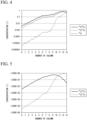
- FIG. 4 shows the concentration distribution of each distillation column in Test Example 3.
- the concentration of the target 18 O in the final column (13th distillation column 13) was 96.3 atomic %, which was slightly below the set value.
- 18 O was concentrated using the stable isotope concentration device 300 shown in FIG.1 .
- the conditions were the same as in Test Example 1 except that the target concentration of 18 O was set to 98 atomic % or more. That is, the flow rate of the gas and the liquid connecting the distillation columns was set to 5% with respect to the flow rate of the ascending gas in each column.
- FIG. 5 shows the concentration distribution of each distillation column in Test Example 4.
- the concentration of the target 18 O in the final column was 98.2 atomic %.
- Test Example 5 the device and the operating conditions were the same as in Test Example 4, except that the flow rate of the gas and the liquid connecting the distillation columns was set to 4% with respect to the flow rate of the ascending gas in each column.
- FIG. 6 shows the concentration distribution of each distillation column in Test Example 5.
- the concentration of the target 18 O in the final column (13th distillation column 13) was 98.0 atomic %.
- Test Example 6 the device and the operating conditions were the same as in Test Example 4, except that the flow rate of the gas and the liquid connecting the distillation columns was set to 3% with respect to the flow rate of the ascending gas in each column.
- FIG. 7 shows the concentration distribution of each distillation column in Test Example 6.
- the concentration of the target 18 O in the final column was 97.6 atomic %, which was below the set value.
- a stable isotope concentration method for concentrating a stable isotope containing a stable isotope atom can be provided by using a distillation apparatus having a group of distillation columns in which a plurality of distillation columns are connected in series (cascaded).
Landscapes
- Chemical & Material Sciences (AREA)
- Chemical Kinetics & Catalysis (AREA)
- Engineering & Computer Science (AREA)
- Physics & Mathematics (AREA)
- Mechanical Engineering (AREA)
- Thermal Sciences (AREA)
- General Engineering & Computer Science (AREA)
- Separation By Low-Temperature Treatments (AREA)
- Other Investigation Or Analysis Of Materials By Electrical Means (AREA)
- Vaporization, Distillation, Condensation, Sublimation, And Cold Traps (AREA)
Abstract
Description
- The present invention relates to a stable isotope concentration method.
- As a method for separating a stable isotope that exists in a very small amount in the natural world, separation methods such as thermal diffusion separation, centrifugal force separation, laser separation, chemical exchange separation, and distillation separation are known. Among these separation methods, distillation separation is suitable for mass production of light elements. Therefore, for example, a water distillation separation or an oxygen distillation separation is adopted as an industrial oxygen stable isotope separation method.
- Stable isotope separation by distillation has a characteristic in that the separation coefficient is extremely close to 1, so several thousand theoretical plates are required to obtain a stable isotope having a high concentration. However, since the height of the distillation column is limited, it is necessary to divide the distillation column into a plurality of distillation columns and connect this plurality of divided distillation columns in series (hereinafter, also referred to as "cascade connection"). In addition, stable isotope has a small natural abundance ratio, so the amount of product is very small compared to the feed amount of a raw material.
- Therefore, among the plurality of distillation columns connected in series, the diameter of the column that feeds the raw material is the largest. The concentration of the product in the column increases as it approaches the end of the recovery section/concentration section, so that the column diameter can be reduced (also called "stepped cascade"). This not only reduces the equipment cost, but also contributes to shortening the start-up time because the amount of liquid hold-up is reduced. On the other hand, in order to reduce the column diameter, it is necessary to provide both a condenser and a reboiler in the column with a reduced diameter, and an increase in power occurs due to an increase in the number of condensers and reboilers.
- Conventionally, in order to connect a plurality of distillation columns, it is common that liquid is supplied from the bottom of an nth distillation column into the top of a next column ((n + 1)th column), and gas is supplied from the top of the nth distillation column into a previous column ((n - 1)th distillation column). On the other hand, in
Patent Document 1, when connecting a plurality of distillation columns, gas is supplied from the bottom of the nth distillation column into the top of the next column ((n + 1)th distillation column), and liquid is supplied from the top of the nth distillation column into the bottom of the previous column ((n - 1)th distillation column). -
Patent Document 1Japanese Patent No. 5132822 - As mentioned above, in isotope separation, a very long distillation column is divided into a plurality of columns, and these columns are connected in series for separation. By providing a condenser and a reboiler in each column, the concentration can be increased. In addition, by reducing the column diameter, excessive power is not required and the start-up time can be shortened. In order to reduce the required power, it is necessary to reduce the operating power of the reboiler that generates an ascending gas in each column and the condenser that generates a descending liquid, and secure a flow rate of the raw material required to connect each column. If the flow rate of the raw material required to connect each column is excessive, the energy consumption of the condenser and the reboiler will increase, and the piping will become large, so the equipment cost will also increase. On the other hand, if the flow rate of the raw material required to connect each column is insufficient, there will be a difference in concentration between the distillation columns, and it will not be possible to concentrate efficiently.
- The present invention has been made in view of the above circumstances, and an object of the present invention is to provide a stable isotope concentration method that reduces equipment cost and power without prolonging the start-up time and enables efficient concentration.
- In order to achieve the object, the present invention uses the following configurations.
- [1] A stable isotope concentration method using multiple cascaded distillation columns (1st column to mth column; m is an integer of 2 or more),
- wherein the method includes a step in which one of gas and liquid is supplied from a position in the vicinity of the bottom of a (n-1)th column to a position in the vicinity of the top of an nth column (1 < n ≦ m), and the other of liquid and gas is returned from a position in the vicinity of the top of the nth column to a position in the vicinity of the bottom of the (n-1)th column; and
- wherein in each distillation column, when a flow rate of an ascending gas in the column is a first flow rate and a flow rate of the gas or the liquid supplied from a previous column or a next column is a second flow rate, the second flow rate is 4% by volume or more with respect to the first flow rate.
- [2] The stable isotope concentration method according to [1], wherein the stable isotope is 18O, and the second flow rate is 4% by volume or more with respect to the first flow rate.
- According to the stable isotope concentration method of the present invention, equipment cost and power can be reduced without prolonging the start-up time, and efficient concentration becomes possible.
-
- [
FIG. 1] FIG. 1 is a system diagram showing a configuration of a stable isotope concentration device applicable to the stable isotope concentration method according to the embodiment of the present invention. - [
FIG. 2] FIG. 2 is a graph for verifying the effect of the present invention. - [
FIG. 3] FIG. 3 is a graph for verifying the effect of the present invention. - [
FIG. 4] FIG. 4 is a graph for verifying the effect of the present invention. - [
FIG. 5] FIG. 5 is a graph for verifying the effect of the present invention. - [
FIG. 6] FIG. 6 is a graph for verifying the effect of the present invention. - [
FIG. 7] FIG. 7 is a graph for verifying the effect of the present invention. - Hereinafter, the present invention will be described in detail with reference to the drawings, showing embodiments.
- In the drawings used in the following description, in order to make the features easier to understand, the featured parts may be enlarged for convenience, and the dimensional ratios of each component may not be the same as the actual ones.
-
FIG. 1 is a system diagram showing a configuration of a stable isotope concentration device applicable to the stable isotope concentration method according to the embodiment of the present invention. - A stable
isotope concentration device 300 of the present embodiment includes a distillation column group in which 13distillation columns 1 to 13 are cascaded, anisotope scrambler condensers reboilers 22, a rawmaterial supply line 30, aproduct recovery line 31, an isotope concentratedgas introduction line 36 and an isotope concentratedgas return line 37. The stableisotope concentration device 300 of the present embodiment is a device that concentrates a stable isotope compound component (hereinafter, may be simply referred to as "stable isotope") containing an arbitrary stable isotope element contained in the raw material compound to a high concentration. - The stable
isotope concentration device 300 further includessupply lines 34 that supply the raw material from the previous column to the next column, andreturn lines 35 that return the raw material from the next column to the previous column between each distillation column. Eachsupply line 34 is provided with an on-offvalve 23. Eachreturn line 35 is provided with an on-offvalve 24. - Hereinafter, the nth distillation column from the upstream end of the distillation column group is referred to as the nth distillation column.
- In
FIG. 1 , due to space limitation, among the first tothirteenth distillation columns 1 to 13, only thefirst distillation column 1 to which a high-purity raw material compound (hereinafter, may be simply referred to as "raw material") is supplied, and the 9th to13th distillation columns 9 to 13 are shown. - The 1st to
13th distillation columns 1 to 13 are cascade-connected in the order of thefirst distillation column 1 to which the raw material is supplied, thesecond distillation column 2, thethird distillation column 3, thefourth distillation column 4, thefifth distillation column 5, thesixth distillation column 6, theseventh distillation column 7, theeighth distillation column 8, theninth distillation column 9, thetenth distillation column 10, theeleventh distillation column 11, thetwelfth distillation column 12, and the thirteenth distillation column 13 (distillation column at the downstream end of the distillation column group). - In the first to
thirteenth distillation columns 1 to 13, by distilling a stable isotope compound containing a stable isotope element (performing a distillation cascade process), a light stable isotope compound having a low boiling point is concentrated on the top side of the columns, and a heavy stable isotope compound with a high boiling point is concentrated on the bottom side of the columns. - Among the first to
thirteenth distillation columns 1 to 13, thefirst distillation column 1 to which the raw material is supplied has the largest distillation load, and therefore has the largest column diameter. In addition, since the abundance ratio of the heavy stable isotope is usually small, from the upstream end to the downstream end, the distillation load gradually decreases from the first distillation column 1 (column diameter decreases). - Sieve trays, structured packings, random packings, and the like (none of which are shown) are provided in each of the first to
thirteenth distillation columns 1 to 13. - One end of the
supply line 34 is connected to a position in the vicinity of the bottom of the column of the (n-1)th distillation column (1 < n ≦ m; m is an integer of 2 or more). Further, the other end of thesupply line 34 is connected to a position in the vicinity of the top of the nth distillation column. The gas in the (n-1)th distillation column is led out into thesupply line 34. The raw material gas led out into thesupply line 34 is introduced into the nth distillation column after the flow rate is controlled by the on-offvalve 23. - One end of the
return line 35 is connected to a position in the vicinity of the top of the nth distillation column. Further, the other end of thereturn line 35 is connected to a position in the vicinity of the bottom of the (n-1)th distillation column (1 < n <- m; m is an integer of 2 or more). The liquid in the nth distillation column is led out into thereturn line 35. The raw material liquid led out into thereturn line 35 is introduced into the (n-1)th distillation column after the flow rate is controlled by the on-offvalve 24. - One
condenser 21 is provided in each distillation column (first tothirteenth distillation columns 1 to 13). - The
condenser 21 is provided on acirculation line 32 in which both ends thereof are connected at different positions at the top of each distillation column. Thecondenser 21 has a function of liquefying the ascending gas in the distillation column by heat exchange and descending the liquid in the distillation column again. Thecondenser 21 can reduce the pressure at the top of each column, and can prevent a decrease in the separation coefficient due to the pressure increase when the columns are connected in series. In the present embodiment, a heat transfer mediumfluid circulation line 38 that circulates the heat transfer medium fluid through the plurality ofcondensers 21 is provided, and heat exchange is performed by the heat transfer medium fluid that circulates through the heat transfer mediumfluid circulation line 38. - One
reboiler 22 is provided for each distillation column. - The
reboiler 22 is provided on acirculation line 33 in which both ends are connected at different positions at the bottom of each distillation column. Thereboiler 22 has a function of vaporizing the descending liquid in the distillation column by heat exchange and ascending the gas in the distillation column again. In the present embodiment, a heat transfer mediumfluid circulation line 39 that circulates the heat transfer fluid through the plurality ofreboilers 22 is provided, and heat exchange is performed by the heat transfer fluid that circulates through the heat transferfluid circulation line 39. - One end of the raw
material supply line 30 is connected to an intermediate portion of thefirst distillation column 1. The rawmaterial supply line 30 is a line that supplies a high-purity raw material into the intermediate portion of thefirst distillation column 1. The rawmaterial supply line 30 is provided with a valve. - The intermediate portion of the distillation column indicates a position other than the top and bottom of the distillation column.
- High purity means that the total impurity concentration of the raw material is 0.001 % or less.
- The stable isotope compound that can be concentrated by the stable isotope concentration method of the present embodiment is not particularly limited. Examples of the stable isotope compound that can be concentrated include oxygen, water, carbon monoxide, nitric oxide and the like.
- One end of the isotope concentrated
gas introduction line 36 is connected to the intermediate portion of thetenth distillation column 10, and the other end is connected to theisotope scrambler 25. Avalve 26 is provided in the isotope concentratedgas introduction line 36. - When the
valve 26 is open, the isotope concentratedgas introduction line 36 leads out a part or all of the raw material compound from thetenth distillation column 10 and supplies it into theisotope scrambler 25. - The raw material compound led out from the
tenth distillation column 10 includes a stable isotope compound concentrated by the first totenth distillation columns 1 to 10. - The
isotope scrambler 25 converts a stable isotope compound containing a stable isotope element into a stable isotope compound containing another stable isotope element by an isotope exchange reaction (isotope scrambling). This makes it possible to obtain a concentrate in which the concentration of the stable isotope compound containing the desired stable isotope element is further increased. The concentrate obtained by theisotope scrambler 25 is returned into thetenth distillation column 10 by the isotope concentratedgas return line 37. - One end of the isotope concentrated
gas return line 37 is connected to theisotope scrambler 25, and the other end is connected to thetenth distillation column 10. A valve 27 is provided in the isotope concentratedgas return line 37. - When the valve 27 is open, the isotope concentrated
gas return line 37 returns the concentrate obtained by further increasing the concentration of the stable isotope compound containing the desired stable isotope element from theisotope scrambler 25 into thetenth distillation column 10. - The raw material compound returned into the
tenth distillation column 10 is distilled in the eleventh tothirteenth distillation columns 11 to 13, and the stable isotope compound containing a desired stable isotope element is further concentrated. - The product recovery line (lead line) 31 is a route for recovering a stable isotope compound containing a concentrated desired stable isotope element as a product. One end of the
product recovery line 31 is connected to a lower portion (position in the vicinity of the bottom) of thethirteenth distillation column 13. - Next, the stable isotope concentration method according to the embodiment of the present invention will be described with reference to
FIG. 1 . In the present embodiment, the stableisotope concentration device 300 shown inFIG. 1 is used to concentrate the stable isotope. - The stable isotope concentration method of the present embodiment is a method for separating a stable isotope using the plurality of cascaded distillation columns (first column to mth column; m is an integer of 2 or more), wherein gas is supplied from a position in the vicinity of the bottom of the (n-1)th column into a position in the vicinity of the top of the nth column (1 < n = m), and liquid is returned from a position in the vicinity of the top of the nth column into a position in the vicinity of the bottom of (n-1)th column.
- Then, in each distillation column (in the stable
isotope concentration device 300 shown inFIG. 1 , thesecond distillation column 2 to the thirteenth distillation column 13), the flow rate of the ascending gas in the column is set as a first flow rate, the flow rate of the gas supplied from the previous column is set as a second flow rate, and the second flow rate is 4% by volume or more with respect to the first flow rate. - Here, according to the stable isotope concentration method of the present embodiment, by setting the second flow rate to 4% by volume or more with respect to the first flow rate, there is substancialty no difference in the concentration between each connection point of column, so that efficient concentration can be achieved. Further, the second flow rate with respect to the first flow rate is more preferably 5% by volume or more.
- Further, as described in Examples later, even when the stable isotope is 18O, it is preferable that the second flow rate be 4% by volume or more with respect to the first flow rate. By operating the stable
isotope concentration device 300 in this way, the abundance of the stable isotope molecules of oxygen gas led out from the bottom of thethirteenth distillation column 13 at the time of stable operation of the device can be adjusted such that the concentration of 18O is 97 atomic% or more. - Further, the upper limit of the second flow rate with respect to the first flow rate is preferably 30% by volume or less from the viewpoint of energy consumption reduction.
- Moreover, in the cascade process, a
return line 35 to the previous column is also required. The flow rate in thereturn line 35 needs to be substantially the same as the flow rate in thesupply line 34. - According to the stable isotope concentration method of the present embodiment, a effective increase in the concentration in the distillation columns can be maintained by adjusting the flow rate of the gas or the liquid connecting the distillation columns to 4 to 30% by volume with respect to the flow rate of the ascending gas (first flow rate) in each column. Thereby, a small variation in the concentration in the distillation columns can be maintained. As a result, the energy consumed by the reboiler and the condenser installed in each column can be reduced, and high-purity products can be obtained.
- As described above, according to the stable isotope concentration method of the present embodiment, it is possible to reduce equipment costs and power consumption without prolonging the start-up time of the stable
isotope concentration device 300, and to achieve efficient concentration. - The technical scope of the present invention is not limited to the embodiments above, and various modifications can be made without departing from the scope of the present invention.
- For example, the number of the distillation columns (cascaded distillation columns) constituting the distillation column group of the stable
isotope concentration device 300 is not limited to 13, but can be any number. The distillation column is not limited to a packed column packed with structured packing, but may be a packed column packed with random packing or a tray column. - The connection of the isotope scrambler is not limited to the
tenth distillation column 10, and may be a distillation column other than thetenth distillation column 10. However, at least one of the distillation columns to which theisotope scrambler 25 is connected is a distillation column other than the distillation column arranged at the downstream end of the distillation column group. In the stableisotope concentration device 300 of the embodiment above, the configuration including theisotope scrambler 25 has been described as an example, but the configuration may be such that theisotope scrambler 25 is unnecessary depending on the fluid used. - In addition, in the stable
isotope concentration device 300 of the embodiment above, the configuration in which the raw material is supplied into the first column has been described as an example, but the present invention is not limited to this embodiment. Depending on the composition of the raw material and the required yield, the raw material may be supplied to columns other than the first column. - In the embodiment above, in the stable
isotope concentration device 300 to which the stable isotope concentration method is used, thecondenser 21 and thereboiler 22 are provided in each distillation column, but the invention is not limited to this embodiment. For example, thecondenser 21 and thereboiler 22 may be provided every several columns. - Further, in the stable
isotope concentration device 300 to which the stable isotope concentration method in the embodiment above is used, the gas is supplied from the position in the vicinity of the bottom of the (n-1)th column into the position in the vicinity of the top of the nth column (1 < n ≤ m), and the liquid is returned from the position in the vicinity of the top of the nth column into the position in the vicinity of the bottom of the (n-1)th column. But the present invention is not limited to this embodiment. In the stable isotope concentration device, the liquid may be supplied from the position in the vicinity of the bottom of the (n-1)th column into a position in the vicinity of the top of the nth column (1 < n ≦ m), and the gas may be supplied from the position in the vicinity of the top of the nth column into the position in the vicinity of the bottom of the (n-1)th column. By adopting such a configuration, the capacities of thecondenser 21 and thereboiler 22 provided in each distillation column can be made smaller. However, since a liquid pump is required to supply the liquid into the next column, it is necessary to adjust the energy consumption. - The present invention will be described in detail below through verification tests, but the present invention is not limited thereto.
- 18O was concentrated using the stable
isotope concentration device 300 shown inFIG. 1 . The distillation column group included 13 distillation columns, and the distillation columns were packed columns. Liquid nitrogen was used as a cold source for thecondenser 21, and the liquid nitrogen was supplied into eachcondenser 21 from the heat mediumfluid circulation line 38. Nitrogen gas was used as a heat source for thereboilers 22, and the nitrogen gas was supplied into each reboiler 22 from the heat mediumfluid circulation line 39. - In addition, the stable
isotope concentration device 300 was provided with theisotope scrambler 25. One end of the isotope enrichedgas introduction line 36 was connected to thetenth distillation column 10, and the other end was connected to theisotope scrambler 25. Accordingly, some or all of the oxygen was led out and supplied into theisotope scrambler 25. The oxygen subjected to the isotope exchange reaction in theisotope scrambler 25 was returned into thetenth distillation column 10 through the isotope enrichedgas return line 37. - The high purity oxygen raw material had the natural abundance ratio. The top pressure of each distillation column was 20 kPaG. When the device was operated stably, the abundance of the stable isotope molecules in the oxygen gas led out from the bottom of the
thirteenth distillation column 13 was set so that 18O was 97 atomic % or more. The flow rate of the gas and the liquid connecting the distillation columns was set to 5% with respect to the flow rate of the ascending gas in each column. -
FIG. 2 shows the concentration distribution of each distillation column in Test Example 1. - As shown in
FIG. 2 , according to Test Example 1, the concentration of the target 18O in the final column (13th distillation column 13) was 97.5 atomic %. - In Test Example 2, the device and the operation conditions were the same as in the Test Example 1, except that the flow rate of the gas and the liquid connecting the distillation columns was set to 4% with respect to the flow rate of the ascending gas in each column.
-
FIG. 3 shows the concentration distribution of each distillation column in Test Example 2. - As shown in
FIG. 3 , according to Test Example 3, the concentration of the target 18O in the final column (13th distillation column 13) was 97.1 atomic %, which was the target value. - In Test Example 3, the device and the operation conditions were the same as in the Test Example 1, except that the flow rate of the gas and the liquid connecting the distillation columns was set to 3% with respect to the flow rate of the ascending gas in each column.
-
FIG. 4 shows the concentration distribution of each distillation column in Test Example 3. - As shown in
FIG. 4 , according to Test Example 3, the concentration of the target 18O in the final column (13th distillation column 13) was 96.3 atomic %, which was slightly below the set value. - In Test Examples 1 and 2, the flow rate of the gas and the liquid connecting the distillation columns was 4% or more with respect to the flow rate of the ascending gas in each column, so that the size of the equipment was appropriate and the energy consumption was optimal.
- On the other hand, in Test Example 3, the flow rate of the gas and the liquid connecting the distillation columns was less than 4% with respect to the flow rate of the ascending gas in each column. Accordingly, a large difference in the concentration distribution of each column was generated, and it was impossible to collect a high-concentration product.
- 18O was concentrated using the stable
isotope concentration device 300 shown inFIG.1 . The conditions were the same as in Test Example 1 except that the target concentration of 18O was set to 98 atomic % or more. That is, the flow rate of the gas and the liquid connecting the distillation columns was set to 5% with respect to the flow rate of the ascending gas in each column. -
FIG. 5 shows the concentration distribution of each distillation column in Test Example 4. - As shown in
FIG. 5 , according to Test Example 4, the concentration of the target 18O in the final column (13th distillation column 13) was 98.2 atomic %. - In Test Example 5, the device and the operating conditions were the same as in Test Example 4, except that the flow rate of the gas and the liquid connecting the distillation columns was set to 4% with respect to the flow rate of the ascending gas in each column.
-
FIG. 6 shows the concentration distribution of each distillation column in Test Example 5. - As shown in
FIG. 6 , according to Test Example 5, the concentration of the target 18O in the final column (13th distillation column 13) was 98.0 atomic %. - In Test Example 6, the device and the operating conditions were the same as in Test Example 4, except that the flow rate of the gas and the liquid connecting the distillation columns was set to 3% with respect to the flow rate of the ascending gas in each column.
-
FIG. 7 shows the concentration distribution of each distillation column in Test Example 6. - As shown in
FIG. 7 , according to Test Example 6, the concentration of the target 18O in the final column (13th distillation column 13) was 97.6 atomic %, which was below the set value. - In Test Examples 4 and 5, the flow rate of the gas and the liquid connecting the distillation columns was 4% or more with respect to the flow rate of the ascending gas in each column, so that the size of the equipment was appropriate and the energy consumption was optimal.
- On the other hand, in Test Example 6, the flow rate of the gas and the liquid connecting the distillation columns was less than 4% with respect to the flow rate of the ascending gas in each column. Accordingly, effective concentration increase through the distillation cascade was not achieved, and it was impossible to produce a high-concentration product.
- It is clear from the results of Verification Tests 1 and 2 that even when the target concentration of 18O, which is the product, was changed (98 atomic % or more, and 97 atomic % or more), a high-concentration product could be collected by adjusting the flow rate of the gas and the liquid connecting the distillation columns with respect to the flow rate of the ascending gas to 4% or more.
- A stable isotope concentration method for concentrating a stable isotope containing a stable isotope atom can be provided by using a distillation apparatus having a group of distillation columns in which a plurality of distillation columns are connected in series (cascaded).
-
- 1, 9, 10, 11, 12, 13
- distillation column
- 21
- condenser
- 22
- reboiler
- 23, 24
- on-off valve
- 25
- isotope scrambler
- 30
- raw material supply line
- 31
- product recovery line (lead out line)
- 34
- supply line
- 35
- return line
- 300
- stable isotope concentration device
Claims (2)
- A stable isotope concentration method using multiple cascaded distillation columns (1st column to mth column; m is an integer of 2 or more),wherein the method includes a step in which one of gas and liquid is supplied from a position in the vicinity of the bottom of a (n-1)th column to a position in the vicinity of the top of an nth column (1 < n ≦ m), and the other of liquid and gas is returned from a position in the vicinity of the top of the nth column to a position in the vicinity of the bottom of the (n-1)th column; andwherein in each distillation column, when a flow rate of an ascending gas in the column is a first flow rate and a flow rate of the gas or the liquid supplied from a previous column or a next column is a second flow rate, the second flow rate is 4% by volume or more with respect to the first flow rate.
- The stable isotope concentration method according to Claim 1, wherein the stable isotope is 18O, and the second flow rate is 4% by volume or more with respect to the first flow rate.
Applications Claiming Priority (2)
| Application Number | Priority Date | Filing Date | Title |
|---|---|---|---|
| JP2020062432A JP6913786B1 (en) | 2020-03-31 | 2020-03-31 | Stable isotope enrichment method |
| PCT/JP2021/008972 WO2021199934A1 (en) | 2020-03-31 | 2021-03-08 | Stable isotope concentrating method |
Publications (3)
| Publication Number | Publication Date |
|---|---|
| EP4129453A1 true EP4129453A1 (en) | 2023-02-08 |
| EP4129453A4 EP4129453A4 (en) | 2024-04-24 |
| EP4129453B1 EP4129453B1 (en) | 2025-08-06 |
Family
ID=77057451
Family Applications (1)
| Application Number | Title | Priority Date | Filing Date |
|---|---|---|---|
| EP21782316.0A Active EP4129453B1 (en) | 2020-03-31 | 2021-03-08 | Stable isotope concentration method |
Country Status (6)
| Country | Link |
|---|---|
| US (1) | US12151208B2 (en) |
| EP (1) | EP4129453B1 (en) |
| JP (1) | JP6913786B1 (en) |
| CN (1) | CN115243784B (en) |
| IL (1) | IL296728B1 (en) |
| WO (1) | WO2021199934A1 (en) |
Families Citing this family (2)
| Publication number | Priority date | Publication date | Assignee | Title |
|---|---|---|---|---|
| CN115920631A (en) * | 2022-12-05 | 2023-04-07 | 中国原子能科学研究院 | Cryogenic rectification device for isotope separation |
| CN115825207B (en) * | 2022-12-08 | 2025-05-02 | 中国原子能科学研究院 | Method for detecting the working status of CO isotope scrambler |
Family Cites Families (17)
| Publication number | Priority date | Publication date | Assignee | Title |
|---|---|---|---|---|
| JPS5315067Y2 (en) | 1974-08-31 | 1978-04-21 | ||
| JPH06134260A (en) * | 1991-09-06 | 1994-05-17 | Tomoshi Kitamoto | Device and method for concentrating oxygen isotope |
| JPH07148419A (en) * | 1993-11-29 | 1995-06-13 | Tomoshi Kitamoto | Method for concentrating oxygen isotope |
| WO2000027509A1 (en) | 1998-11-09 | 2000-05-18 | Nippon Sanso Corporation | Method and apparatus for enrichment of heavy component of oxygen isotopes |
| DE69907616T2 (en) | 1998-12-28 | 2004-03-11 | Nippon Sanso Corp. | Vapor-liquid contactor, cryogenic air separation unit and process for gas separation |
| JP4327287B2 (en) | 1999-01-29 | 2009-09-09 | 大陽日酸株式会社 | Method and apparatus for producing heavy oxygen water |
| JP4495279B2 (en) | 1999-10-12 | 2010-06-30 | 大陽日酸株式会社 | Distillation apparatus, oxygen isotope weight component concentration method, and heavy oxygen water production method |
| JP3505503B2 (en) | 2000-11-22 | 2004-03-08 | 康一 浅野 | Method and apparatus for separating and concentrating a mixture having a separation coefficient close to 1 by distillation |
| JP5122443B2 (en) * | 2006-03-23 | 2013-01-16 | 大陽日酸株式会社 | Nitrogen isotope concentration method |
| JP5026774B2 (en) | 2006-11-28 | 2012-09-19 | 大陽日酸株式会社 | Distillation equipment |
| JP5009358B2 (en) * | 2009-12-28 | 2012-08-22 | 大陽日酸株式会社 | Distillation apparatus and oxygen isotope enrichment method |
| JP5132822B1 (en) | 2012-03-27 | 2013-01-30 | 大陽日酸株式会社 | Distillation equipment |
| JP5813613B2 (en) * | 2012-10-18 | 2015-11-17 | 大陽日酸株式会社 | Oxygen isotope enrichment method |
| CN103055697B (en) * | 2013-01-16 | 2016-03-23 | 江苏正能同位素有限公司 | The method and apparatus of a kind of enrichment method stable isotope 2H, 18O, 13C |
| JP6172684B2 (en) * | 2015-01-20 | 2017-08-02 | 大陽日酸株式会社 | Oxygen isotope enrichment method |
| JP6214586B2 (en) | 2015-03-18 | 2017-10-18 | 大陽日酸株式会社 | Regeneration and concentration method for oxygen isotope weight component, oxygen isotope weight component regeneration and concentration apparatus |
| JP6606522B2 (en) * | 2017-03-28 | 2019-11-13 | 大陽日酸株式会社 | Carbon monoxide stable isotope enrichment apparatus and carbon monoxide stable isotope enrichment method |
-
2020
- 2020-03-31 JP JP2020062432A patent/JP6913786B1/en active Active
-
2021
- 2021-03-08 US US17/914,971 patent/US12151208B2/en active Active
- 2021-03-08 IL IL296728A patent/IL296728B1/en unknown
- 2021-03-08 WO PCT/JP2021/008972 patent/WO2021199934A1/en not_active Ceased
- 2021-03-08 CN CN202180019822.2A patent/CN115243784B/en active Active
- 2021-03-08 EP EP21782316.0A patent/EP4129453B1/en active Active
Also Published As
| Publication number | Publication date |
|---|---|
| JP6913786B1 (en) | 2021-08-04 |
| EP4129453B1 (en) | 2025-08-06 |
| IL296728B1 (en) | 2026-04-01 |
| EP4129453A4 (en) | 2024-04-24 |
| CN115243784A (en) | 2022-10-25 |
| JP2021159831A (en) | 2021-10-11 |
| WO2021199934A1 (en) | 2021-10-07 |
| CN115243784B (en) | 2025-07-11 |
| US12151208B2 (en) | 2024-11-26 |
| US20230104429A1 (en) | 2023-04-06 |
| IL296728A (en) | 2022-11-01 |
Similar Documents
| Publication | Publication Date | Title |
|---|---|---|
| US7001490B2 (en) | Purification of ammonia by distillation | |
| EP4129453B1 (en) | Stable isotope concentration method | |
| US6835287B1 (en) | Apparatus, method for enrichment of the heavy isotope oxygen and production method for heavy oxygen water | |
| EP1997551B1 (en) | Method for concentration of heavy nitrogen isotope | |
| EP2910298B1 (en) | Method for condensing oxygen isotopes | |
| EP2837904B1 (en) | Distillation device | |
| CN101597031B (en) | Method for intermittently producing deuterium depleted water through heavy-oxygen-enriched water separation device and device thereof | |
| EP1927387B1 (en) | Distillation apparatus | |
| JP6606522B2 (en) | Carbon monoxide stable isotope enrichment apparatus and carbon monoxide stable isotope enrichment method | |
| KR930001593B1 (en) | Process for recovering hydrogen-free higher boiling synthesis gas component | |
| US9168467B1 (en) | Assembly for separating gas mixtures in fractionating columns | |
| US20230302407A1 (en) | Carbon stable isotope enrichment method | |
| JP6865798B2 (en) | How to operate the carbon monoxide stable isotope concentrator and the carbon monoxide stable isotope | |
| EP4245403A1 (en) | Stable isotope concentrating device | |
| Jianga et al. | Process intensification in multicomponent distillation | |
| JP6913772B2 (en) | Stable isotope concentrator | |
| US20060005574A1 (en) | Method for extracting argon by low-temperature air separation | |
| KR20020027181A (en) | Structured packing system for reduced distillation column height | |
| EP0892233A2 (en) | Column configuration and method for argon production | |
| JP7512240B2 (en) | How to restart the isotope separator | |
| CN121775657A (en) | A method and apparatus for the distillation separation of boron isotopes |
Legal Events
| Date | Code | Title | Description |
|---|---|---|---|
| STAA | Information on the status of an ep patent application or granted ep patent |
Free format text: STATUS: THE INTERNATIONAL PUBLICATION HAS BEEN MADE |
|
| PUAI | Public reference made under article 153(3) epc to a published international application that has entered the european phase |
Free format text: ORIGINAL CODE: 0009012 |
|
| STAA | Information on the status of an ep patent application or granted ep patent |
Free format text: STATUS: REQUEST FOR EXAMINATION WAS MADE |
|
| 17P | Request for examination filed |
Effective date: 20220922 |
|
| AK | Designated contracting states |
Kind code of ref document: A1 Designated state(s): AL AT BE BG CH CY CZ DE DK EE ES FI FR GB GR HR HU IE IS IT LI LT LU LV MC MK MT NL NO PL PT RO RS SE SI SK SM TR |
|
| DAV | Request for validation of the european patent (deleted) | ||
| DAX | Request for extension of the european patent (deleted) | ||
| A4 | Supplementary search report drawn up and despatched |
Effective date: 20240327 |
|
| RIC1 | Information provided on ipc code assigned before grant |
Ipc: B01D 59/04 20060101AFI20240321BHEP |
|
| GRAP | Despatch of communication of intention to grant a patent |
Free format text: ORIGINAL CODE: EPIDOSNIGR1 |
|
| STAA | Information on the status of an ep patent application or granted ep patent |
Free format text: STATUS: GRANT OF PATENT IS INTENDED |
|
| RIC1 | Information provided on ipc code assigned before grant |
Ipc: F25J 3/08 20060101ALI20250331BHEP Ipc: B01D 3/42 20060101ALI20250331BHEP Ipc: B01D 3/14 20060101ALI20250331BHEP Ipc: B01D 59/04 20060101AFI20250331BHEP |
|
| INTG | Intention to grant announced |
Effective date: 20250415 |
|
| GRAS | Grant fee paid |
Free format text: ORIGINAL CODE: EPIDOSNIGR3 |
|
| GRAA | (expected) grant |
Free format text: ORIGINAL CODE: 0009210 |
|
| STAA | Information on the status of an ep patent application or granted ep patent |
Free format text: STATUS: THE PATENT HAS BEEN GRANTED |
|
| P01 | Opt-out of the competence of the unified patent court (upc) registered |
Free format text: CASE NUMBER: APP_28282/2025 Effective date: 20250612 |
|
| AK | Designated contracting states |
Kind code of ref document: B1 Designated state(s): AL AT BE BG CH CY CZ DE DK EE ES FI FR GB GR HR HU IE IS IT LI LT LU LV MC MK MT NL NO PL PT RO RS SE SI SK SM TR |
|
| REG | Reference to a national code |
Ref country code: GB Ref legal event code: FG4D |
|
| REG | Reference to a national code |
Ref country code: CH Ref legal event code: EP |
|
| REG | Reference to a national code |
Ref country code: DE Ref legal event code: R096 Ref document number: 602021035705 Country of ref document: DE |
|
| REG | Reference to a national code |
Ref country code: IE Ref legal event code: FG4D |
|
| REG | Reference to a national code |
Ref country code: CH Ref legal event code: R17 Free format text: ST27 STATUS EVENT CODE: U-0-0-R10-R17 (AS PROVIDED BY THE NATIONAL OFFICE) Effective date: 20251014 |
|
| REG | Reference to a national code |
Ref country code: NL Ref legal event code: MP Effective date: 20250806 |
|
| PG25 | Lapsed in a contracting state [announced via postgrant information from national office to epo] |
Ref country code: IS Free format text: LAPSE BECAUSE OF FAILURE TO SUBMIT A TRANSLATION OF THE DESCRIPTION OR TO PAY THE FEE WITHIN THE PRESCRIBED TIME-LIMIT Effective date: 20251206 |
|
| PG25 | Lapsed in a contracting state [announced via postgrant information from national office to epo] |
Ref country code: NO Free format text: LAPSE BECAUSE OF FAILURE TO SUBMIT A TRANSLATION OF THE DESCRIPTION OR TO PAY THE FEE WITHIN THE PRESCRIBED TIME-LIMIT Effective date: 20251106 |
|
| REG | Reference to a national code |
Ref country code: LT Ref legal event code: MG9D |
|
| PG25 | Lapsed in a contracting state [announced via postgrant information from national office to epo] |
Ref country code: PT Free format text: LAPSE BECAUSE OF FAILURE TO SUBMIT A TRANSLATION OF THE DESCRIPTION OR TO PAY THE FEE WITHIN THE PRESCRIBED TIME-LIMIT Effective date: 20251209 |
|
| PG25 | Lapsed in a contracting state [announced via postgrant information from national office to epo] |
Ref country code: FI Free format text: LAPSE BECAUSE OF FAILURE TO SUBMIT A TRANSLATION OF THE DESCRIPTION OR TO PAY THE FEE WITHIN THE PRESCRIBED TIME-LIMIT Effective date: 20250806 |
|
| PG25 | Lapsed in a contracting state [announced via postgrant information from national office to epo] |
Ref country code: HR Free format text: LAPSE BECAUSE OF FAILURE TO SUBMIT A TRANSLATION OF THE DESCRIPTION OR TO PAY THE FEE WITHIN THE PRESCRIBED TIME-LIMIT Effective date: 20250806 Ref country code: NL Free format text: LAPSE BECAUSE OF FAILURE TO SUBMIT A TRANSLATION OF THE DESCRIPTION OR TO PAY THE FEE WITHIN THE PRESCRIBED TIME-LIMIT Effective date: 20250806 |
|
| PG25 | Lapsed in a contracting state [announced via postgrant information from national office to epo] |
Ref country code: GR Free format text: LAPSE BECAUSE OF FAILURE TO SUBMIT A TRANSLATION OF THE DESCRIPTION OR TO PAY THE FEE WITHIN THE PRESCRIBED TIME-LIMIT Effective date: 20251107 |
|
| PG25 | Lapsed in a contracting state [announced via postgrant information from national office to epo] |
Ref country code: SE Free format text: LAPSE BECAUSE OF FAILURE TO SUBMIT A TRANSLATION OF THE DESCRIPTION OR TO PAY THE FEE WITHIN THE PRESCRIBED TIME-LIMIT Effective date: 20250806 |
|
| PG25 | Lapsed in a contracting state [announced via postgrant information from national office to epo] |
Ref country code: LV Free format text: LAPSE BECAUSE OF FAILURE TO SUBMIT A TRANSLATION OF THE DESCRIPTION OR TO PAY THE FEE WITHIN THE PRESCRIBED TIME-LIMIT Effective date: 20250806 |
|
| PG25 | Lapsed in a contracting state [announced via postgrant information from national office to epo] |
Ref country code: PL Free format text: LAPSE BECAUSE OF FAILURE TO SUBMIT A TRANSLATION OF THE DESCRIPTION OR TO PAY THE FEE WITHIN THE PRESCRIBED TIME-LIMIT Effective date: 20250806 Ref country code: BG Free format text: LAPSE BECAUSE OF FAILURE TO SUBMIT A TRANSLATION OF THE DESCRIPTION OR TO PAY THE FEE WITHIN THE PRESCRIBED TIME-LIMIT Effective date: 20250806 |
|
| PG25 | Lapsed in a contracting state [announced via postgrant information from national office to epo] |
Ref country code: RS Free format text: LAPSE BECAUSE OF FAILURE TO SUBMIT A TRANSLATION OF THE DESCRIPTION OR TO PAY THE FEE WITHIN THE PRESCRIBED TIME-LIMIT Effective date: 20251106 |
|
| PG25 | Lapsed in a contracting state [announced via postgrant information from national office to epo] |
Ref country code: ES Free format text: LAPSE BECAUSE OF FAILURE TO SUBMIT A TRANSLATION OF THE DESCRIPTION OR TO PAY THE FEE WITHIN THE PRESCRIBED TIME-LIMIT Effective date: 20250806 |
|
| REG | Reference to a national code |
Ref country code: AT Ref legal event code: MK05 Ref document number: 1821183 Country of ref document: AT Kind code of ref document: T Effective date: 20250806 |
|
| PG25 | Lapsed in a contracting state [announced via postgrant information from national office to epo] |
Ref country code: SM Free format text: LAPSE BECAUSE OF FAILURE TO SUBMIT A TRANSLATION OF THE DESCRIPTION OR TO PAY THE FEE WITHIN THE PRESCRIBED TIME-LIMIT Effective date: 20250806 |
|
| PGFP | Annual fee paid to national office [announced via postgrant information from national office to epo] |
Ref country code: GB Payment date: 20260304 Year of fee payment: 6 |
|
| REG | Reference to a national code |
Ref country code: CH Ref legal event code: U11 Free format text: ST27 STATUS EVENT CODE: U-0-0-U10-U11 (AS PROVIDED BY THE NATIONAL OFFICE) Effective date: 20260410 |
|
| PG25 | Lapsed in a contracting state [announced via postgrant information from national office to epo] |
Ref country code: DK Free format text: LAPSE BECAUSE OF FAILURE TO SUBMIT A TRANSLATION OF THE DESCRIPTION OR TO PAY THE FEE WITHIN THE PRESCRIBED TIME-LIMIT Effective date: 20250806 |
|
| PGFP | Annual fee paid to national office [announced via postgrant information from national office to epo] |
Ref country code: DE Payment date: 20260304 Year of fee payment: 6 |
|
| PG25 | Lapsed in a contracting state [announced via postgrant information from national office to epo] |
Ref country code: AT Free format text: LAPSE BECAUSE OF FAILURE TO SUBMIT A TRANSLATION OF THE DESCRIPTION OR TO PAY THE FEE WITHIN THE PRESCRIBED TIME-LIMIT Effective date: 20250806 |
|
| PG25 | Lapsed in a contracting state [announced via postgrant information from national office to epo] |
Ref country code: IT Free format text: LAPSE BECAUSE OF FAILURE TO SUBMIT A TRANSLATION OF THE DESCRIPTION OR TO PAY THE FEE WITHIN THE PRESCRIBED TIME-LIMIT Effective date: 20250806 |
|
| PGFP | Annual fee paid to national office [announced via postgrant information from national office to epo] |
Ref country code: BE Payment date: 20260303 Year of fee payment: 6 |
|
| PGFP | Annual fee paid to national office [announced via postgrant information from national office to epo] |
Ref country code: FR Payment date: 20260310 Year of fee payment: 6 |
|
| PG25 | Lapsed in a contracting state [announced via postgrant information from national office to epo] |
Ref country code: CZ Free format text: LAPSE BECAUSE OF FAILURE TO SUBMIT A TRANSLATION OF THE DESCRIPTION OR TO PAY THE FEE WITHIN THE PRESCRIBED TIME-LIMIT Effective date: 20250806 |
|
| PG25 | Lapsed in a contracting state [announced via postgrant information from national office to epo] |
Ref country code: EE Free format text: LAPSE BECAUSE OF FAILURE TO SUBMIT A TRANSLATION OF THE DESCRIPTION OR TO PAY THE FEE WITHIN THE PRESCRIBED TIME-LIMIT Effective date: 20250806 Ref country code: SK Free format text: LAPSE BECAUSE OF FAILURE TO SUBMIT A TRANSLATION OF THE DESCRIPTION OR TO PAY THE FEE WITHIN THE PRESCRIBED TIME-LIMIT Effective date: 20250806 |