EP4129450A2 - Carbon dioxide adsorption on amine grafted solid adsorbent and adsorbent regeneration - Google Patents
Carbon dioxide adsorption on amine grafted solid adsorbent and adsorbent regeneration Download PDFInfo
- Publication number
- EP4129450A2 EP4129450A2 EP22188364.8A EP22188364A EP4129450A2 EP 4129450 A2 EP4129450 A2 EP 4129450A2 EP 22188364 A EP22188364 A EP 22188364A EP 4129450 A2 EP4129450 A2 EP 4129450A2
- Authority
- EP
- European Patent Office
- Prior art keywords
- absorption
- carbon dioxide
- bed
- absorption bed
- way valve
- Prior art date
- Legal status (The legal status is an assumption and is not a legal conclusion. Google has not performed a legal analysis and makes no representation as to the accuracy of the status listed.)
- Pending
Links
- CURLTUGMZLYLDI-UHFFFAOYSA-N Carbon dioxide Chemical compound O=C=O CURLTUGMZLYLDI-UHFFFAOYSA-N 0.000 title claims abstract description 338
- 229910002092 carbon dioxide Inorganic materials 0.000 title claims abstract description 169
- 239000001569 carbon dioxide Substances 0.000 title claims abstract description 169
- 150000001412 amines Chemical class 0.000 title claims abstract description 54
- 239000007787 solid Substances 0.000 title claims abstract description 39
- 239000003463 adsorbent Substances 0.000 title 2
- 230000008929 regeneration Effects 0.000 title 1
- 238000011069 regeneration method Methods 0.000 title 1
- 238000001179 sorption measurement Methods 0.000 title 1
- 238000010521 absorption reaction Methods 0.000 claims abstract description 367
- 239000002904 solvent Substances 0.000 claims abstract description 192
- 239000007788 liquid Substances 0.000 claims abstract description 108
- 239000011324 bead Substances 0.000 claims abstract description 40
- 239000002594 sorbent Substances 0.000 claims abstract description 40
- 238000003795 desorption Methods 0.000 claims description 45
- 238000000034 method Methods 0.000 claims description 31
- 238000004590 computer program Methods 0.000 claims description 11
- LCGLNKUTAGEVQW-UHFFFAOYSA-N Dimethyl ether Chemical group COC LCGLNKUTAGEVQW-UHFFFAOYSA-N 0.000 claims description 10
- 239000002202 Polyethylene glycol Substances 0.000 claims description 5
- 229920001223 polyethylene glycol Polymers 0.000 claims description 5
- 229920006395 saturated elastomer Polymers 0.000 description 7
- 238000001311 chemical methods and process Methods 0.000 description 2
- 238000006243 chemical reaction Methods 0.000 description 2
- 230000000694 effects Effects 0.000 description 2
- 238000002360 preparation method Methods 0.000 description 2
- 238000012545 processing Methods 0.000 description 2
- 238000000926 separation method Methods 0.000 description 2
- XTHFKEDIFFGKHM-UHFFFAOYSA-N Dimethoxyethane Chemical compound COCCOC XTHFKEDIFFGKHM-UHFFFAOYSA-N 0.000 description 1
- 230000005540 biological transmission Effects 0.000 description 1
- 230000015556 catabolic process Effects 0.000 description 1
- 238000004891 communication Methods 0.000 description 1
- 238000006731 degradation reaction Methods 0.000 description 1
- 238000009429 electrical wiring Methods 0.000 description 1
- 230000005670 electromagnetic radiation Effects 0.000 description 1
- 239000000835 fiber Substances 0.000 description 1
- 239000000463 material Substances 0.000 description 1
- 238000005259 measurement Methods 0.000 description 1
- 238000012986 modification Methods 0.000 description 1
- 230000004048 modification Effects 0.000 description 1
- 230000003287 optical effect Effects 0.000 description 1
- 238000005086 pumping Methods 0.000 description 1
- 230000001172 regenerating effect Effects 0.000 description 1
- 239000011555 saturated liquid Substances 0.000 description 1
- 230000009919 sequestration Effects 0.000 description 1
Images

Classifications
-
- B—PERFORMING OPERATIONS; TRANSPORTING
- B01—PHYSICAL OR CHEMICAL PROCESSES OR APPARATUS IN GENERAL
- B01D—SEPARATION
- B01D53/00—Separation of gases or vapours; Recovering vapours of volatile solvents from gases; Chemical or biological purification of waste gases, e.g. engine exhaust gases, smoke, fumes, flue gases, aerosols
- B01D53/34—Chemical or biological purification of waste gases
- B01D53/96—Regeneration, reactivation or recycling of reactants
-
- B—PERFORMING OPERATIONS; TRANSPORTING
- B01—PHYSICAL OR CHEMICAL PROCESSES OR APPARATUS IN GENERAL
- B01D—SEPARATION
- B01D53/00—Separation of gases or vapours; Recovering vapours of volatile solvents from gases; Chemical or biological purification of waste gases, e.g. engine exhaust gases, smoke, fumes, flue gases, aerosols
- B01D53/02—Separation of gases or vapours; Recovering vapours of volatile solvents from gases; Chemical or biological purification of waste gases, e.g. engine exhaust gases, smoke, fumes, flue gases, aerosols by adsorption, e.g. preparative gas chromatography
-
- B—PERFORMING OPERATIONS; TRANSPORTING
- B01—PHYSICAL OR CHEMICAL PROCESSES OR APPARATUS IN GENERAL
- B01D—SEPARATION
- B01D19/00—Degasification of liquids
- B01D19/0036—Flash degasification
-
- B—PERFORMING OPERATIONS; TRANSPORTING
- B01—PHYSICAL OR CHEMICAL PROCESSES OR APPARATUS IN GENERAL
- B01D—SEPARATION
- B01D53/00—Separation of gases or vapours; Recovering vapours of volatile solvents from gases; Chemical or biological purification of waste gases, e.g. engine exhaust gases, smoke, fumes, flue gases, aerosols
- B01D53/34—Chemical or biological purification of waste gases
- B01D53/346—Controlling the process
-
- B—PERFORMING OPERATIONS; TRANSPORTING
- B01—PHYSICAL OR CHEMICAL PROCESSES OR APPARATUS IN GENERAL
- B01D—SEPARATION
- B01D53/00—Separation of gases or vapours; Recovering vapours of volatile solvents from gases; Chemical or biological purification of waste gases, e.g. engine exhaust gases, smoke, fumes, flue gases, aerosols
- B01D53/34—Chemical or biological purification of waste gases
- B01D53/46—Removing components of defined structure
- B01D53/62—Carbon oxides
-
- B—PERFORMING OPERATIONS; TRANSPORTING
- B01—PHYSICAL OR CHEMICAL PROCESSES OR APPARATUS IN GENERAL
- B01D—SEPARATION
- B01D53/00—Separation of gases or vapours; Recovering vapours of volatile solvents from gases; Chemical or biological purification of waste gases, e.g. engine exhaust gases, smoke, fumes, flue gases, aerosols
- B01D53/34—Chemical or biological purification of waste gases
- B01D53/74—General processes for purification of waste gases; Apparatus or devices specially adapted therefor
- B01D53/81—Solid phase processes
- B01D53/82—Solid phase processes with stationary reactants
-
- B—PERFORMING OPERATIONS; TRANSPORTING
- B01—PHYSICAL OR CHEMICAL PROCESSES OR APPARATUS IN GENERAL
- B01D—SEPARATION
- B01D2253/00—Adsorbents used in seperation treatment of gases and vapours
- B01D2253/20—Organic adsorbents
-
- B—PERFORMING OPERATIONS; TRANSPORTING
- B01—PHYSICAL OR CHEMICAL PROCESSES OR APPARATUS IN GENERAL
- B01D—SEPARATION
- B01D2253/00—Adsorbents used in seperation treatment of gases and vapours
- B01D2253/25—Coated, impregnated or composite adsorbents
-
- B—PERFORMING OPERATIONS; TRANSPORTING
- B01—PHYSICAL OR CHEMICAL PROCESSES OR APPARATUS IN GENERAL
- B01D—SEPARATION
- B01D2257/00—Components to be removed
- B01D2257/50—Carbon oxides
- B01D2257/504—Carbon dioxide
-
- B—PERFORMING OPERATIONS; TRANSPORTING
- B01—PHYSICAL OR CHEMICAL PROCESSES OR APPARATUS IN GENERAL
- B01D—SEPARATION
- B01D2258/00—Sources of waste gases
- B01D2258/06—Polluted air
-
- B—PERFORMING OPERATIONS; TRANSPORTING
- B01—PHYSICAL OR CHEMICAL PROCESSES OR APPARATUS IN GENERAL
- B01D—SEPARATION
- B01D2259/00—Type of treatment
- B01D2259/45—Gas separation or purification devices adapted for specific applications
- B01D2259/4566—Gas separation or purification devices adapted for specific applications for use in transportation means
- B01D2259/4575—Gas separation or purification devices adapted for specific applications for use in transportation means in aeroplanes or space ships
-
- Y—GENERAL TAGGING OF NEW TECHNOLOGICAL DEVELOPMENTS; GENERAL TAGGING OF CROSS-SECTIONAL TECHNOLOGIES SPANNING OVER SEVERAL SECTIONS OF THE IPC; TECHNICAL SUBJECTS COVERED BY FORMER USPC CROSS-REFERENCE ART COLLECTIONS [XRACs] AND DIGESTS
- Y02—TECHNOLOGIES OR APPLICATIONS FOR MITIGATION OR ADAPTATION AGAINST CLIMATE CHANGE
- Y02C—CAPTURE, STORAGE, SEQUESTRATION OR DISPOSAL OF GREENHOUSE GASES [GHG]
- Y02C20/00—Capture or disposal of greenhouse gases
- Y02C20/40—Capture or disposal of greenhouse gases of CO2
Definitions
- the subject matter disclosed herein relates generally to the field of removing carbon dioxide gas, and specifically to an apparatus for absorbing and removing carbon dioxide gas and humidity from an enclosed space.
- a regenerative carbon dioxide removal system is utilized for this purpose and commonly includes amine beds that are placed in contact with a flow of carbon dioxide laden air. The amine beds adsorb carbon dioxide from the air stream through chemical processes and reactions.
- An amine bed is utilized until it is saturated to a selected saturation level.
- the selected saturation level can be a saturation level where the amine bed can no longer efficiently remove carbon dioxide from an air stream or any saturation level less than the saturation level where the amine bed can no longer efficiently remove carbon dioxide from the air stream.
- Another amine bed is then switched into contact with the carbon dioxide laden air stream. The saturated amine bed is then desorbed to expel carbon dioxide in preparation for the next cycle.
- a swing bed absorption apparatus including a first absorption bed including a first plurality of solid amine based sorbent beads, a second absorption bed including a second plurality of solid amine based sorbent beads, and a solvent pump configured to alternately pump a liquid solvent through the first absorption bed and the second absorption bed.
- the liquid solvent is configured to alternately desorb the carbon dioxide from the first plurality of solid amine based sorbent beads and the second plurality of solid amine based sorbent beads.
- further embodiments may include a drum inlet passage to receive the liquid solvent from the first absorption bed and the second absorption bed.
- further embodiments may include a drum inlet passage, and a flash drum fluidly connected to the drum inlet passage, the flash drum being configured to receive the liquid solvent from the drum inlet passage.
- the flash drum is configured to separate the liquid solvent in a liquid form and the carbon dioxide in a gaseous form.
- further embodiments may include a carbon dioxide blower.
- the flash drum further includes: a top and a bottom opposite the top, a flash drum gas exit passage fluidly connecting the top of the flash drum to the carbon dioxide blower.
- the carbon dioxide blower is configured to remove the carbon dioxide from the flash drum.
- the flash drum further includes a flash drum liquid exit passageway fluidly connected to the bottom of the flash drum. The flash drum liquid exit passageway configured to provide the liquid solvent to the solvent pump.
- further embodiments may include a first three-way valve configured to switch between a first absorption bed position and a second absorption bed position, a second three-way valve configured to switch between a first absorption bed absorption position and a first absorption bed desorption position, and a third three-way valve configured to switch between a second absorption bed absorption position and a second absorption bed desorption position.
- the first three-way valve is configured to fluidly connect a carbon dioxide laden airstream to the second three-way valve in the first absorption bed position.
- the first three-way valve is configured to fluidly connect the carbon dioxide laden airstream to the third three-way valve in the second absorption bed position.
- further embodiments may include that the second three-way valve is configured to fluidly connect the first three-way valve to the first absorption bed in the first absorption bed absorption position.
- the second three-way valve is configured to fluidly connect the first absorption bed to the drum inlet passage in the first absorption bed desorption position.
- further embodiments may include that the third three-way valve is configured to fluidly connect the first three-way valve to the second absorption bed in the second absorption bed absorption position.
- the third three-way valve is configured to fluidly connect the second absorption bed to the drum inlet passage in the second absorption bed desorption position.
- further embodiments may include a fourth three-way valve configured to switch between a first absorption bed solvent side position and a second absorption bed solvent side position, a fifth three-way valve configured to switch between a first absorption bed absorption solvent side position and a first absorption bed desorption solvent side position, and a sixth three-way valve configured to switch between a second absorption bed absorption solvent side position and a second absorption bed desorption solvent side position.
- the fourth three-way valve is configured to fluidly connect the solvent pump to the fifth three-way valve in the first absorption bed solvent side position.
- the fourth three-way valve is configured to fluidly connect the solvent pump to the sixth three-way valve in the second absorption bed solvent side position.
- further embodiments may include that the fifth three-way valve is configured to fluidly connect a purified stream blower to the first absorption bed in the first absorption bed absorption solvent side position.
- the fifth three-way valve is configured to fluidly connect the first absorption bed to the fourth three-way valve in the first absorption bed desorption solvent side position.
- further embodiments may include that the sixth three-way valve is configured to fluidly connect a purified stream blower to the second absorption bed in the second absorption bed absorption solvent side position.
- the sixth three-way valve is configured to fluidly connect the second absorption bed to the fourth three-way valve in the second absorption bed desorption solvent side position.
- liquid solvent has a solubility for the carbon dioxide equal to or greater than 3.6 liters of the carbon dioxide per liter of the liquid solvent (0.95 gallons of the carbon dioxide per gallon of the liquid solvent).
- liquid solvent is dimethyl ether of polyethylene glycol.
- a method of removing carbon dioxide from a carbon dioxide laden airstream includes flowing the carbon dioxide laden airstream through a first absorption bed including a first plurality of solid amine based sorbent beads configured to absorb the carbon dioxide from the carbon dioxide laden airstream, ceasing flow of the carbon dioxide laden airstream through the first absorption bed, and flowing liquid solvent through the first absorption bed when flow of the carbon dioxide laden airstream through the first absorption bed has ceased.
- the liquid solvent is configured to desorb the carbon dioxide from the first plurality of solid amine based sorbent beads.
- further embodiments may include flowing the carbon dioxide laden airstream through a second absorption bed when flow of the carbon dioxide laden airstream through the first absorption bed has ceased.
- the second absorption bed including a second plurality of solid amine based sorbent beads configured to absorb the carbon dioxide from the carbon dioxide laden airstream.
- further embodiments may include ceasing flow of the liquid solvent through the first absorption bed, ceasing flow of the carbon dioxide laden airstream through the second absorption bed when flow of the liquid solvent through the first absorption bed has ceased, and flowing liquid solvent through the second absorption bed when the flow of the carbon dioxide laden airstream through the second absorption bed has ceased.
- the liquid solvent is configured to desorb the carbon dioxide from the second plurality of solid amine based sorbent beads.
- further embodiments may include flowing the carbon dioxide laden airstream through the first absorption bed when flow of the liquid solvent through the first absorption bed has ceased and when the flow of the carbon dioxide laden airstream through the second absorption bed has ceased.
- further embodiments may include separating the carbon dioxide from the liquid solvent using a flash drum and removing the carbon dioxide from the flash drum.
- liquid solvent has a solubility for the carbon dioxide equal to or greater than 2 liters of the carbon dioxide per liter of the liquid solvent (0.52 gallons of the carbon dioxide per gallon of the liquid solvent).
- liquid solvent is dimethyl ether of polyethylene glycol.
- a computer program product tangibly embodied on a non-transitory computer readable medium including instructions that, when executed by a processor, cause the processor to perform operations including controlling one or more valves to a flow a carbon dioxide laden airstream through a first absorption bed including a first plurality of solid amine based sorbent beads configured to absorb carbon dioxide from the carbon dioxide laden airstream, controlling the one or more valves to cease the flow of the carbon dioxide laden airstream through the first absorption bed, and controlling another one or more valves to flow liquid solvent through the first absorption bed when the flow of the carbon dioxide laden airstream through the first absorption bed has ceased.
- the liquid solvent is configured to desorb the carbon dioxide from the first plurality of solid amine based sorbent beads.
- An amine bed for a swing bed absorption apparatus is typically filled with amine-based sorbent beads that adsorb carbon dioxide from the air stream through chemical processes and reactions.
- An amine bed is utilized until it is saturated to a selected saturation level.
- the selected saturation level can be a saturation level where the amine bed can no longer efficiently remove carbon dioxide from an air stream or any saturation level less than the saturation level where the amine bed can no longer efficiently remove carbon dioxide from the air stream, for example.
- Another amine bed is then switched into contact with the carbon dioxide laden air stream. The saturated amine bed is then desorbed to expel carbon dioxide in preparation for the next cycle.
- the desorption process requires a vacuum and a great deal of time to remove the carbon dioxide from the amine-based sorbent beads.
- Conventional swing bed absorption apparatus are typically utilized in space to remove carbon dioxide in environments for astronauts. Since space is a vacuum, the vacuum of space is conventionally used for the desorption process. However, for terrestrial application, such as on earth, vacuums are not plentiful.
- the embodiments disclosed herein seek to provide apparatus and methods for absorbing and removing carbon dioxide gas and humidity from an enclosed space without the aid of the vacuum of space.
- the embodiments disclosed herein utilize a multiple-bed swing absorption process with at least two absorption beds each containing solid amine based sorbent beads. While one absorption bed is absorbing the other absorption bed is desorbing.
- the solid amine based sorbent beads absorb carbon dioxide directly from the gas phase without additional liquid solvents.
- the desorption process disclosed herein uses a liquid solvent having high carbon dioxide solubility to facilitate the process with pressurization via pumping required for the final flash separation to obtain the purified carbon dioxide stream.
- a high carbon dioxide solubility may be defined as a solubility for carbon dioxide 204 equal to or greater than 3 volumes of the carbon dioxide 204 per one volume of liquid solvent 202 at ambient temperature and pressure.
- the exemplary swing bed absorption apparatus 200 is composed of a first absorption bed 240a and a second absorption bed 240b (generally referred to as 240).
- the first absorption bed 240a includes a first plurality of solid amine based sorbent beads 242a and the second absorption bed 240b includes a second plurality of solid amine based sorbent beads 242b.
- the exemplary swing bed absorption apparatus 200 of FIG. 1 includes two absorption beds 240a, 240b, the embodiments disclosed herein may be applicable to a swing bed absorption apparatus 200 with more than two absorption beds 240.
- the swing bed absorption apparatus 200 is configured to flow carbon dioxide laden airstream 210 through the first absorption bed 240a until the solid amine based sorbent beads 242a of first absorption bed 240a reach a selected saturation level and then the swing bed absorption apparatus 200 is configured to flow carbon dioxide laden airstream 210 through the second absorption bed 240b while desorbing the carbon dioxide 204 from the first plurality of solid amine based sorbent beads 242a of the first absorption bed 240a using a liquid solvent 202.
- the liquid solvent 202 may be a high soluble desorption liquid solvent.
- the liquid solvent 202 may be dimethyl ether of polyethylene glycol (DEPG) (i.e., Selexol).
- the liquid solvent 202 has a solubility for carbon dioxide 204 equal to or greater than 2 liters of the carbon dioxide 204 per liter of liquid solvent 202 (0.52 gallons of the carbon dioxide 204 per gallon of liquid solvent 202). This solubility may be measured at a pressure of 1 bar (14.50 psi) and a temperature of 0°C (32°F). In another embodiment, the liquid solvent 202 has a solubility for carbon dioxide 204 equal to or greater than 3.6 liters of the carbon dioxide 204 per liter of liquid solvent 202 (0.95 gallons of the carbon dioxide 204 per gallon of liquid solvent 202).
- This solubility may be measured at a pressure of 1 bar (14.50 psi) and a temperature of 0°C (32°F).
- the saturated liquid solvent 202 is passed through a flash drum 256 where it can be separated into a purified stream of carbon dioxide 204 and then the liquid solvent 202 is recycled for continued desorption of carbon dioxide 204.
- the use of liquid solvents 202 is both easier and more energy efficient to increase pressure for the flash separation comparted to using gas streams.
- the swing bed absorption apparatus 200 includes a first three-way valve 220, a second three-way valve 222, a third three-way valve 224, a fourth three-way valve 230, a fifth three-way valve 232, a sixth three-way valve 234, a purified stream blower 252, a carbon dioxide blower 254, the flash drum 256, and a solvent pump 258. It is understood that a solvent expander may be required in the swing bed absorption apparatus 200 if there is not a sufficient pressure reduction effect on the liquid solvent 202 from flowing through the absorption beds, 240a, 240b alone. The solvent expander may exist between the absorption beds 240a, 240b and the flash drum 256.
- the first three-way valve 220 fluidly connects the swing bed absorption apparatus 200 to a carbon dioxide laden airstream 210.
- the first three-way valve 220 is configured to switch between a first absorption bed position, ultimately leading to the first absorption bed 240a and a second absorption bed position, ultimately leading to the second absorption bed 240b.
- the first three-way valve 220 In the first absorption bed position, the first three-way valve 220 is configured to fluidly connect the carbon dioxide laden airstream 210 to the second three-way valve 222.
- the first three-way valve 220 is configured to fluidly connect the carbon dioxide laden airstream 210 to a first absorption bed connector passage 260.
- the first absorption bed connector passage 260 fluidly connects the first three-way valve 220 to the second three-way valve 222.
- the carbon dioxide laden airstream 210 is configured to flow through the first three-way valve 220 to the second three-way valve 222.
- the first three-way valve 220 is configured to fluidly connect the carbon dioxide laden airstream 210 to the third three-way valve 224.
- the first three-way valve 220 is configured to fluidly connect the carbon dioxide laden airstream 210 to a second absorption bed connector passage 262.
- the second absorption bed connector passage 262 fluidly connects the first three-way valve 220 to the third three-way valve 224.
- the carbon dioxide laden airstream 210 is configured to flow through the first three-way valve 220 to the third three-way valve 224.
- the second three-way valve 222 is configured to switch between a first absorption bed absorption position and a first absorption bed desorption position.
- the second three-way valve 222 is configured to fluidly connect the first three-way valve 220 to the first absorption bed 240a.
- the second three-way valve 222 is configured to fluidly connect the first absorption bed connector passage 260 to a first absorption bed inlet passage 264.
- the first absorption bed inlet passage 264 fluidly connects the second three-way valve 222 to the first absorption bed 240a.
- the carbon dioxide laden airstream 210 is configured to flow from the first three-way valve 220 through the second three-way valve 222 to the first absorption bed 240a.
- the second three-way valve 222 is configured to fluidly connect the first absorption bed 240a to a drum inlet passage 280.
- the second three-way valve 222 is configured to fluidly connect the first absorption bed inlet passage 264 to a first solvent passage 282.
- the first solvent passage 282 fluidly connects the second three-way valve 222 to the drum inlet passage 280.
- liquid solvent 202 is configured to flow from the first absorption bed 240a through the second three-way valve 222 to the drum inlet passage 280.
- the drum inlet passage 280 is configured to receive the liquid solvent 202 from the first absorption bed 240a and the second absorption bed 240b.
- the third three-way valve 224 is configured to switch between a second absorption bed absorption position and a second absorption bed desorption position.
- the third three-way valve 224 is configured to fluidly connect the first three-way valve 220 to the second absorption bed 240b.
- the third three-way valve 224 is configured to fluidly connect the second absorption bed connector passage 262 to a second absorption bed inlet passage 266.
- the second absorption bed inlet passage 266 fluidly connects the third three-way valve 224 to the second absorption bed 240b.
- the carbon dioxide laden airstream 210 is configured to flow from the first three-way valve 220 through the third three-way valve 224 to the second absorption bed 240b.
- the third three-way valve 224 is configured to fluidly connect the second absorption bed 240b to the drum inlet passage 280.
- the third three-way valve 224 is configured to fluidly connect the second absorption bed inlet passage 266 to a second solvent passage 284.
- the second solvent passage 284 fluidly connects the third three-way valve 224 to the drum inlet passage 280.
- liquid solvent 202 is configured to flow from second absorption bed 240b through the third three-way valve 224 to the drum inlet passage 280.
- the liquid solvent 202 is configured to absorb the carbon dioxide 204 from the solid amine based sorbent beads 242a, 242b in the first absorption bed 240a and the second absorption bed 240b.
- the liquid solvent 202 is transported to the flash drum 256 with the carbon dioxide 204.
- the flash drum 256 is configured to expand the liquid solvent 202, thus reducing the pressure of the liquid solvent 202.
- the flash drum 256 is configured to separate the liquid solvent 202 in a liquid form and the carbon dioxide 204 in a gaseous form.
- the carbon dioxide 204 in the gaseous form will rise to a top 257 of the flash drum 256 and exit the flash drum 256 through a flash drum gas exit passage 292.
- a bottom 259 of the flash drum 256 is located opposite the top 257.
- the flash drum gas exit passage 292 fluidly connects the top 257 of the flash drum 256 to the carbon dioxide blower 254.
- the carbon dioxide blower 254 is configured to remove the carbon dioxide 204 from the flash drum 256.
- the liquid solvent 202 in liquid form will fall to the bottom 259 of the flash drum 256 and exit the flash drum 256 through a flash drum liquid exit passageway 294.
- the flash drum liquid exit passageway 294 is fluidly connected to the bottom 259 of the flash drum 256.
- the flash drum liquid exit passageway 294 fluidly connects the flash drum 256 to the solvent pump 258.
- the flash drum liquid exit passageway 294 is configured to provide the liquid solvent 202 back to the solvent pump 258 after the carbon dioxide 204 has been removed in the flash drum 256.
- the solvent pump 258 is fluidly connected to the fourth three-way valve 230 through a solvent entry passageway 286.
- the solvent pump 258 is configured to alternately pump the liquid solvent 202 through the first absorption bed 240a and the second absorption bed 240b. Further, the solvent pump 258 is configured to pump the liquid solvent 202 through the first absorption bed 240a and the second absorption bed 240b in an alternating sequence, such that liquid solvent 202 may only be pumped through one of the first absorption bed 240a and the second absorption bed 240b at any given time but never both at the same time.
- the liquid solvent 202 is configured to alternately desorb the carbon dioxide 204 from the first plurality of solid amine based sorbent beads 242a and the second plurality of solid amine based sorbent beads 242b.
- the fifth three-way valve 232 is configured to switch between a first absorption bed absorption solvent side position and a first absorption bed desorption solvent side position. In the first absorption bed absorption solvent side position, the fifth three-way valve 232 is configured to fluidly connect the purified stream blower 252 to the first absorption bed 240a. In other words, in the first absorption bed absorption solvent side position, the fifth three-way valve 232 is configured to fluidly connect a first absorption bed outlet passage 268 to a first absorption bed purified stream passage 270. The first absorption bed outlet passage 268 fluidly connects the fifth three-way valve 232 to the first absorption bed 240a.
- the first absorption bed purified stream passage 270 fluidly connects the fifth three-way valve 232 to the purified stream blower 252.
- purified air that is free of carbon dioxide 204 is configured to flow from the first absorption bed 240a through the fifth three-way valve 232 to the purified stream blower 252.
- the purified stream blower 252 is configured to deliver the purified air to collection area where it may be compressed for utilization or sequestration
- the fifth three-way valve 232 is configured to fluidly connect the first absorption bed 240a to the fourth three-way valve 230.
- the fifth three-way valve 232 is configured to fluidly connect the first absorption bed outlet passage 268 to a first absorption bed solvent connector passage 272.
- the first absorption bed solvent connector passage 272 fluidly connects the fifth three-way valve 232 to the fourth three-way valve 230.
- liquid solvent 202 is configured to flow from fourth three-way valve 230 through the fifth three-way valve 232 to the first absorption bed 240a.
- the sixth three-way valve 234 is configured to switch between a second absorption bed absorption solvent side position and a second absorption bed desorption solvent side position. In the second absorption bed absorption solvent side position, the sixth three-way valve 234 is configured to fluidly connect the purified stream blower to the second absorption bed 240b. In other words, in the second absorption bed absorption solvent side position, the sixth three-way valve 234 is configured to fluidly connect a second absorption bed outlet passage 274 to a second absorption bed purified stream passage 276. The second absorption bed outlet passage 274 fluidly connects the sixth three-way valve 234 to the second absorption bed 240b.
- the second absorption bed purified stream passage 276 fluidly connects the sixth three-way valve 234 to the purified stream blower 252.
- purified air that is free of carbon dioxide 204 is configured to flow from the second absorption bed 240b through the sixth three-way valve 234 to the purified stream blower 252.
- the sixth three-way valve 234 is configured to fluidly connect the second absorption bed 240b to the fourth three-way valve 230.
- the sixth three-way valve 234 in the second absorption bed desorption solvent side position, is configured to fluidly connect the second absorption bed outlet passage 274 to a second absorption bed solvent connector passage 278.
- the second absorption bed solvent connector passage 278 fluidly connects the sixth three-way valve 234 to the fourth three-way valve 230.
- liquid solvent 202 is configured to flow from fourth three-way valve 230 through the sixth three-way valve 234 to the second absorption bed 240b.
- the fourth three-way valve 230 is fluidly connected to the solvent pump 258 and is configured to deliver liquid solvent 202 from the solvent pump 258 to at least one of the first absorption bed 240a and the second absorption bed 240b.
- the fourth three-way valve 230 is configured to switch between a first absorption bed solvent side position and a second absorption bed solvent side position. In the first absorption bed solvent side position, the fourth three-way valve 230 is configured to fluidly connect the solvent pump 258 to the fifth three-way valve 232. In other words, in the first absorption bed solvent side position, the fourth three-way valve 230 is configured to fluidly connect the solvent pump 258 to the first absorption bed solvent connector passage 272. In the first absorption bed solvent side position, liquid solvent 202 is configured to flow from the solvent pump 258 through the fourth three-way valve 230 to the fifth three-way valve 232.
- the fourth three-way valve 230 is configured to fluidly connect the solvent pump 258 to the sixth three-way valve 234.
- the fourth three-way valve 230 is configured to fluidly connect the solvent pump 258 to a second absorption bed solvent connector passage 278.
- the second absorption bed solvent connector passage 278 fluidly connects the fourth three-way valve 230 to the sixth three-way valve 234.
- liquid solvent 202 is configured to flow from the solvent pump 258 through the fourth three-way valve to the sixth three-way valve 234.
- the swing bed absorption apparatus 200 may also include a controller 300 configured to control positions of the three-ways valves 220, 222, 224, 230, 232, 234.
- the controller 300 may also be configured to control operation of the solvent pump 258, the purified stream blower 252, and the carbon dioxide blower 254.
- the controller 300 may be an electronic controller including a processor 320 and an associated memory 310 comprising computer-executable instructions (i.e., computer program product) that, when executed by the processor 320, cause the processor to perform various operations.
- the processor 320 may be, but is not limited to, a single-processor or multi-processor system of any of a wide array of possible architectures, including field programmable gate array (FPGA), central processing unit (CPU), application specific integrated circuits (ASIC), digital signal processor (DSP) or graphics processing unit (GPU) hardware arranged homogenously or heterogeneously.
- the memory 310 may be but is not limited to a random access memory (RAM), read only memory (ROM), or other electronic, optical, magnetic or any other computer readable medium.
- controller 300 When the first absorption bed 240a is absorbing the controller 300 is configured to adjust the first three-way valve 220 to the first absorption bed position, adjust the second three-way valve 222 to the first absorption bed absorption position, and adjust the fifth three-way valve 232 to the first absorption bed absorption solvent side position.
- the second absorption bed 240b may be desorbing when the first absorption bed 240a is absorbing.
- the controller 300 is configured to adjust the fourth three-way valve 230 to the second absorption bed solvent side position, adjust the sixth three-way valve 234 to the second absorption bed desorption solvent side position, and adjust the third three-way valve 224 to the second absorption bed desorption position.
- controller 300 When the second absorption bed 240b is absorbing the controller 300 is configured to adjust the first three-way valve 220 to the second absorption bed position, adjust the third three-way valve 224 to the second absorption bed absorption position, and adjust the sixth three-way valve 234 to the second absorption bed absorption solvent side position.
- the first absorption bed 240a may be desorbing when the second absorption bed 240b is absorbing.
- the controller 300 is configured to adjust the fourth three-way valve 230 to the first absorption bed solvent side position, adjust the fifth three-way valve 232 to the first absorption bed desorption solvent side position, and adjust the second three-way valve 222 to the first absorption bed desorption position.
- the controller 300 may be in communication with one or more sensors 350, 352, 354, 356 to help monitor and control the swing bed absorption apparatus 200.
- a first sensor 350 may be located in or connected to the first absorption bed outlet passage 268 and the second absorption bed outlet passage 274 to monitor any changes the concentration of carbon dioxide 204, which helps the controller 300 control bed switching based on a current saturation level of the absorption beds 240a, 240b. If the first sensor 350 begins detecting carbon dioxide in the first absorption bed outlet passage 268 during the absorption process of the first absorption bed 240a then it may mean that the first absorption bed 240a is fully saturated. If the first sensor 350 begins detecting carbon dioxide 204 in the second absorption bed outlet passage 274 during the absorption process of the second absorption bed 240b then it may mean that that second absorption bed 240b is fully saturated.
- a second sensor 252 may be located in or connected to the first absorption bed inlet passage 264 and the second absorption bed inlet passage 266 to monitor any changes in the concentration of carbon dioxide 204, which helps the controller 300 control bed switching based on a current desorption level of the absorption beds 240a, 240b.
- the second sensor 252 begins detecting no carbon dioxide 204 in the first absorption bed inlet passage 264 during desorption process of the first absorption bed 240a then it may be that the first absorption bed 240a is fully desaturated. If the second sensor 252 begins detecting no carbon dioxide 204 in the second absorption bed inlet passage 266 during the desorption process of the second absorption bed 240b then it may mean that that second absorption bed 242b is fully desaturated.
- a third sensor 254 may be located in or connected to the flash drum liquid exit passageway 294 to ensure purity (e.g., no carbon dioxide 204) in the solvent 202 upon exiting the flash drum 256.
- a fourth sensor 256 may be located in or connected to the inlet of the flash drum 256 to detect the concentration of carbon dioxide 204 in the solvent 202 to see if there is too much carbon dioxide 204 in the solvent 202, which may lead to a degradation of the ability of the solvent 202 to desorb.
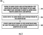
- FIG. 2 a flow chart of method 400 of removing carbon dioxide 204 from a carbon dioxide laden airstream 210 is illustrated, in accordance with an embodiment of the disclosure.
- the method 400 may be performed by the swing bed absorption apparatus 200 and controlled by the controller 300.
- the carbon dioxide laden airstream 210 is flowed through a first absorption bed 240a comprising a first plurality of solid amine based sorbent beads 242a configured to absorb carbon dioxide 204 from the carbon dioxide laden airstream 210.
- liquid solvent 202 is flowed through the first absorption bed 240a when the flow of the carbon dioxide laden airstream 210 through the first absorption bed 240a has ceased.
- the liquid solvent 202 is configured to desorb the carbon dioxide 204 from the first plurality of solid amine based sorbent beads 242a.
- the method 400 may include additional iterations involving the second absorption bed 240b in turn.
- the carbon dioxide laden airstream 210 is flowed through a second absorption bed 240b when the flow of the carbon dioxide laden airstream 210 through the first absorption bed 240a has ceased.
- the second absorption bed 240b comprising a second plurality of solid amine based sorbent beads 242b is configured to absorb carbon dioxide 204 from the carbon dioxide laden airstream 210.
- the flow of the liquid solvent 202 through the first absorption bed 240a may be ceased and then the flow of the carbon dioxide laden airstream 210 through the second absorption bed 240b may be ceased when flow of the liquid solvent 202 through the first absorption bed 240a has ceased. Then liquid solvent 202 may be flowed through the second absorption bed 240b when the flow of the carbon dioxide laden airstream 210 through the second absorption bed 240b has ceased.
- the liquid solvent 202 is configured to desorb the carbon dioxide 204 from the second plurality of solid amine based sorbent beads 242b.
- the method 400 may then include that the carbon dioxide laden airstream 210 is flowed through the first absorption bed 240a when flow of the liquid solvent 202 through the first absorption bed 240a has ceased and when the flow of the carbon dioxide laden airstream 210 through the second absorption bed 240b has ceased.
- the method 400 may also include separating the carbon dioxide 204 from the liquid solvent 202 using a flash drum 256 and removing the carbon dioxide 204 from the flash drum 256.
- a swing bed comprising two absorption beds and alternating the flow of carbon dioxide laden airflow with a liquid solvent through each absorption bed.
- embodiments can be in the form of processor-implemented processes and devices for practicing those processes, such as processor.
- Embodiments can also be in the form of computer program code (e.g., computer program product) containing instructions embodied in tangible media (e.g., non-transitory computer readable medium), such as floppy diskettes, CD ROMs, hard drives, or any other non-transitory computer readable medium, wherein, when the computer program code is loaded into and executed by a computer, the computer becomes a device for practicing the embodiments.
- Embodiments can also be in the form of computer program code, for example, whether stored in a storage medium, loaded into and/or executed by a computer, or transmitted over some transmission medium, such as over electrical wiring or cabling, through fiber optics, or via electromagnetic radiation, wherein, when the computer program code is loaded into and executed by a computer, the computer becomes an device for practicing the exemplary embodiments.
- the computer program code segments configure the microprocessor to create specific logic circuits.
Landscapes
- Chemical & Material Sciences (AREA)
- Engineering & Computer Science (AREA)
- Chemical Kinetics & Catalysis (AREA)
- Environmental & Geological Engineering (AREA)
- Analytical Chemistry (AREA)
- General Chemical & Material Sciences (AREA)
- Oil, Petroleum & Natural Gas (AREA)
- Health & Medical Sciences (AREA)
- Biomedical Technology (AREA)
- Life Sciences & Earth Sciences (AREA)
- Sustainable Development (AREA)
- Gas Separation By Absorption (AREA)
Abstract
Description
- The subject matter disclosed herein relates generally to the field of removing carbon dioxide gas, and specifically to an apparatus for absorbing and removing carbon dioxide gas and humidity from an enclosed space.
- Life support systems that are utilized in enclosed spaces such as submarines, spacecraft or space suits require the continuous removal of carbon dioxide. A regenerative carbon dioxide removal system is utilized for this purpose and commonly includes amine beds that are placed in contact with a flow of carbon dioxide laden air. The amine beds adsorb carbon dioxide from the air stream through chemical processes and reactions.
- An amine bed is utilized until it is saturated to a selected saturation level. The selected saturation level can be a saturation level where the amine bed can no longer efficiently remove carbon dioxide from an air stream or any saturation level less than the saturation level where the amine bed can no longer efficiently remove carbon dioxide from the air stream. Another amine bed is then switched into contact with the carbon dioxide laden air stream. The saturated amine bed is then desorbed to expel carbon dioxide in preparation for the next cycle.
- According to one embodiment, a swing bed absorption apparatus is provided. The swing bed absorption apparatus including a first absorption bed including a first plurality of solid amine based sorbent beads, a second absorption bed including a second plurality of solid amine based sorbent beads, and a solvent pump configured to alternately pump a liquid solvent through the first absorption bed and the second absorption bed. The liquid solvent is configured to alternately desorb the carbon dioxide from the first plurality of solid amine based sorbent beads and the second plurality of solid amine based sorbent beads.
- In addition to one or more of the features described above, or as an alternative, further embodiments may include a drum inlet passage to receive the liquid solvent from the first absorption bed and the second absorption bed.
- In addition to one or more of the features described above, or as an alternative, further embodiments may include a drum inlet passage, and a flash drum fluidly connected to the drum inlet passage, the flash drum being configured to receive the liquid solvent from the drum inlet passage. The flash drum is configured to separate the liquid solvent in a liquid form and the carbon dioxide in a gaseous form.
- In addition to one or more of the features described above, or as an alternative, further embodiments may include a carbon dioxide blower. The flash drum further includes: a top and a bottom opposite the top, a flash drum gas exit passage fluidly connecting the top of the flash drum to the carbon dioxide blower. The carbon dioxide blower is configured to remove the carbon dioxide from the flash drum. The flash drum further includes a flash drum liquid exit passageway fluidly connected to the bottom of the flash drum. The flash drum liquid exit passageway configured to provide the liquid solvent to the solvent pump.
- In addition to one or more of the features described above, or as an alternative, further embodiments may include a first three-way valve configured to switch between a first absorption bed position and a second absorption bed position, a second three-way valve configured to switch between a first absorption bed absorption position and a first absorption bed desorption position, and a third three-way valve configured to switch between a second absorption bed absorption position and a second absorption bed desorption position. The first three-way valve is configured to fluidly connect a carbon dioxide laden airstream to the second three-way valve in the first absorption bed position. The first three-way valve is configured to fluidly connect the carbon dioxide laden airstream to the third three-way valve in the second absorption bed position.
- In addition to one or more of the features described above, or as an alternative, further embodiments may include that the second three-way valve is configured to fluidly connect the first three-way valve to the first absorption bed in the first absorption bed absorption position. The second three-way valve is configured to fluidly connect the first absorption bed to the drum inlet passage in the first absorption bed desorption position.
- In addition to one or more of the features described above, or as an alternative, further embodiments may include that the third three-way valve is configured to fluidly connect the first three-way valve to the second absorption bed in the second absorption bed absorption position. The third three-way valve is configured to fluidly connect the second absorption bed to the drum inlet passage in the second absorption bed desorption position.
- In addition to one or more of the features described above, or as an alternative, further embodiments may include a fourth three-way valve configured to switch between a first absorption bed solvent side position and a second absorption bed solvent side position, a fifth three-way valve configured to switch between a first absorption bed absorption solvent side position and a first absorption bed desorption solvent side position, and a sixth three-way valve configured to switch between a second absorption bed absorption solvent side position and a second absorption bed desorption solvent side position. The fourth three-way valve is configured to fluidly connect the solvent pump to the fifth three-way valve in the first absorption bed solvent side position. The fourth three-way valve is configured to fluidly connect the solvent pump to the sixth three-way valve in the second absorption bed solvent side position.
- In addition to one or more of the features described above, or as an alternative, further embodiments may include that the fifth three-way valve is configured to fluidly connect a purified stream blower to the first absorption bed in the first absorption bed absorption solvent side position. The fifth three-way valve is configured to fluidly connect the first absorption bed to the fourth three-way valve in the first absorption bed desorption solvent side position.
- In addition to one or more of the features described above, or as an alternative, further embodiments may include that the sixth three-way valve is configured to fluidly connect a purified stream blower to the second absorption bed in the second absorption bed absorption solvent side position. The sixth three-way valve is configured to fluidly connect the second absorption bed to the fourth three-way valve in the second absorption bed desorption solvent side position.
- In addition to one or more of the features described above, or as an alternative, further embodiments may include that the liquid solvent has a solubility for the carbon dioxide equal to or greater than 3.6 liters of the carbon dioxide per liter of the liquid solvent (0.95 gallons of the carbon dioxide per gallon of the liquid solvent).
- In addition to one or more of the features described above, or as an alternative, further embodiments may include that the liquid solvent is dimethyl ether of polyethylene glycol.
- According to another embodiment, a method of removing carbon dioxide from a carbon dioxide laden airstream is provided. The method includes flowing the carbon dioxide laden airstream through a first absorption bed including a first plurality of solid amine based sorbent beads configured to absorb the carbon dioxide from the carbon dioxide laden airstream, ceasing flow of the carbon dioxide laden airstream through the first absorption bed, and flowing liquid solvent through the first absorption bed when flow of the carbon dioxide laden airstream through the first absorption bed has ceased. The liquid solvent is configured to desorb the carbon dioxide from the first plurality of solid amine based sorbent beads.
- In addition to one or more of the features described above, or as an alternative, further embodiments may include flowing the carbon dioxide laden airstream through a second absorption bed when flow of the carbon dioxide laden airstream through the first absorption bed has ceased. The second absorption bed including a second plurality of solid amine based sorbent beads configured to absorb the carbon dioxide from the carbon dioxide laden airstream.
- In addition to one or more of the features described above, or as an alternative, further embodiments may include ceasing flow of the liquid solvent through the first absorption bed, ceasing flow of the carbon dioxide laden airstream through the second absorption bed when flow of the liquid solvent through the first absorption bed has ceased, and flowing liquid solvent through the second absorption bed when the flow of the carbon dioxide laden airstream through the second absorption bed has ceased. The liquid solvent is configured to desorb the carbon dioxide from the second plurality of solid amine based sorbent beads.
- In addition to one or more of the features described above, or as an alternative, further embodiments may include flowing the carbon dioxide laden airstream through the first absorption bed when flow of the liquid solvent through the first absorption bed has ceased and when the flow of the carbon dioxide laden airstream through the second absorption bed has ceased.
- In addition to one or more of the features described above, or as an alternative, further embodiments may include separating the carbon dioxide from the liquid solvent using a flash drum and removing the carbon dioxide from the flash drum.
- In addition to one or more of the features described above, or as an alternative, further embodiments may include that the liquid solvent has a solubility for the carbon dioxide equal to or greater than 2 liters of the carbon dioxide per liter of the liquid solvent (0.52 gallons of the carbon dioxide per gallon of the liquid solvent).
- In addition to one or more of the features described above, or as an alternative, further embodiments may include that the liquid solvent is dimethyl ether of polyethylene glycol.
- According to another embodiment, a computer program product tangibly embodied on a non-transitory computer readable medium is provided. The computer program product including instructions that, when executed by a processor, cause the processor to perform operations including controlling one or more valves to a flow a carbon dioxide laden airstream through a first absorption bed including a first plurality of solid amine based sorbent beads configured to absorb carbon dioxide from the carbon dioxide laden airstream, controlling the one or more valves to cease the flow of the carbon dioxide laden airstream through the first absorption bed, and controlling another one or more valves to flow liquid solvent through the first absorption bed when the flow of the carbon dioxide laden airstream through the first absorption bed has ceased. The liquid solvent is configured to desorb the carbon dioxide from the first plurality of solid amine based sorbent beads.
- The foregoing features and elements may be combined in various combinations without exclusivity, unless expressly indicated otherwise. These features and elements as well as the operation thereof will become more apparent in light of the following description and the accompanying drawings. It should be understood, however, that the following description and drawings are intended to be illustrative and explanatory in nature and non-limiting.
- The following descriptions should not be considered limiting in any way. With reference to the accompanying drawings, like elements are numbered alike:
-
FIG. 1 illustrates a schematic view of a swing bed absorption apparatus, according to an embodiment of the present disclosure; and -
FIG. 2 illustrates a flow chart of a method of removing carbon dioxide from a carbon dioxide laden airstream, in accordance with an embodiment of the present disclosure. - A detailed description of one or more embodiments of the disclosed apparatus and method are presented herein by way of exemplification and not limitation with reference to the Figures.
- An amine bed for a swing bed absorption apparatus is typically filled with amine-based sorbent beads that adsorb carbon dioxide from the air stream through chemical processes and reactions. An amine bed is utilized until it is saturated to a selected saturation level. The selected saturation level can be a saturation level where the amine bed can no longer efficiently remove carbon dioxide from an air stream or any saturation level less than the saturation level where the amine bed can no longer efficiently remove carbon dioxide from the air stream, for example. Another amine bed is then switched into contact with the carbon dioxide laden air stream. The saturated amine bed is then desorbed to expel carbon dioxide in preparation for the next cycle.
- Conventionally, the desorption process requires a vacuum and a great deal of time to remove the carbon dioxide from the amine-based sorbent beads. Conventional swing bed absorption apparatus are typically utilized in space to remove carbon dioxide in environments for astronauts. Since space is a vacuum, the vacuum of space is conventionally used for the desorption process. However, for terrestrial application, such as on earth, vacuums are not plentiful. The embodiments disclosed herein seek to provide apparatus and methods for absorbing and removing carbon dioxide gas and humidity from an enclosed space without the aid of the vacuum of space. The embodiments disclosed herein utilize a multiple-bed swing absorption process with at least two absorption beds each containing solid amine based sorbent beads. While one absorption bed is absorbing the other absorption bed is desorbing. If the absorption process is faster than the desorption process, multiple beds can be desorbing while one bed is actively absorbing. This allows for continuous operation and process that is scalable. The solid amine based sorbent beads absorb carbon dioxide directly from the gas phase without additional liquid solvents. The desorption process disclosed herein uses a liquid solvent having high carbon dioxide solubility to facilitate the process with pressurization via pumping required for the final flash separation to obtain the purified carbon dioxide stream. A high carbon dioxide solubility may be defined as a solubility for
carbon dioxide 204 equal to or greater than 3 volumes of thecarbon dioxide 204 per one volume of liquid solvent 202 at ambient temperature and pressure. - Referring now to
FIG. 1 , a schematic view of a swingbed absorption apparatus 200 is illustrated, according to an embodiment of the present disclosure. The exemplary swingbed absorption apparatus 200 is composed of a first absorption bed 240a and asecond absorption bed 240b (generally referred to as 240). The first absorption bed 240a includes a first plurality of solid amine basedsorbent beads 242a and thesecond absorption bed 240b includes a second plurality of solid amine basedsorbent beads 242b. It is understood that while the exemplary swingbed absorption apparatus 200 ofFIG. 1 includes twoabsorption beds 240a, 240b, the embodiments disclosed herein may be applicable to a swingbed absorption apparatus 200 with more than two absorption beds 240. - The swing
bed absorption apparatus 200 is configured to flow carbon dioxideladen airstream 210 through the first absorption bed 240a until the solid amine basedsorbent beads 242a of first absorption bed 240a reach a selected saturation level and then the swingbed absorption apparatus 200 is configured to flow carbon dioxideladen airstream 210 through thesecond absorption bed 240b while desorbing thecarbon dioxide 204 from the first plurality of solid amine basedsorbent beads 242a of the first absorption bed 240a using a liquid solvent 202. In an embodiment, the liquid solvent 202 may be a high soluble desorption liquid solvent. In an embodiment, the liquid solvent 202 may be dimethyl ether of polyethylene glycol (DEPG) (i.e., Selexol). In an embodiment, the liquid solvent 202 has a solubility forcarbon dioxide 204 equal to or greater than 2 liters of thecarbon dioxide 204 per liter of liquid solvent 202 (0.52 gallons of thecarbon dioxide 204 per gallon of liquid solvent 202). This solubility may be measured at a pressure of 1 bar (14.50 psi) and a temperature of 0°C (32°F). In another embodiment, the liquid solvent 202 has a solubility forcarbon dioxide 204 equal to or greater than 3.6 liters of thecarbon dioxide 204 per liter of liquid solvent 202 (0.95 gallons of thecarbon dioxide 204 per gallon of liquid solvent 202). This solubility may be measured at a pressure of 1 bar (14.50 psi) and a temperature of 0°C (32°F). Once the liquid solvent 202 is saturated with thecarbon dioxide 204 from the solid amine basedsorbent beads flash drum 256 where it can be separated into a purified stream ofcarbon dioxide 204 and then the liquid solvent 202 is recycled for continued desorption ofcarbon dioxide 204. Advantageously, the use ofliquid solvents 202 is both easier and more energy efficient to increase pressure for the flash separation comparted to using gas streams. - The swing
bed absorption apparatus 200 includes a first three-way valve 220, a second three-way valve 222, a third three-way valve 224, a fourth three-way valve 230, a fifth three-way valve 232, a sixth three-way valve 234, a purifiedstream blower 252, acarbon dioxide blower 254, theflash drum 256, and asolvent pump 258. It is understood that a solvent expander may be required in the swingbed absorption apparatus 200 if there is not a sufficient pressure reduction effect on the liquid solvent 202 from flowing through the absorption beds, 240a, 240b alone. The solvent expander may exist between theabsorption beds 240a, 240b and theflash drum 256. - The first three-
way valve 220 fluidly connects the swingbed absorption apparatus 200 to a carbon dioxideladen airstream 210. The first three-way valve 220 is configured to switch between a first absorption bed position, ultimately leading to the first absorption bed 240a and a second absorption bed position, ultimately leading to thesecond absorption bed 240b. In the first absorption bed position, the first three-way valve 220 is configured to fluidly connect the carbon dioxideladen airstream 210 to the second three-way valve 222. In other words, in the first absorption bed position, the first three-way valve 220 is configured to fluidly connect the carbon dioxideladen airstream 210 to a first absorptionbed connector passage 260. The first absorptionbed connector passage 260 fluidly connects the first three-way valve 220 to the second three-way valve 222. In the first absorption bed position, the carbon dioxideladen airstream 210 is configured to flow through the first three-way valve 220 to the second three-way valve 222. - In the second absorption bed position, the first three-
way valve 220 is configured to fluidly connect the carbon dioxideladen airstream 210 to the third three-way valve 224. In other words, in the second absorption bed position, the first three-way valve 220 is configured to fluidly connect the carbon dioxideladen airstream 210 to a second absorptionbed connector passage 262. The second absorptionbed connector passage 262 fluidly connects the first three-way valve 220 to the third three-way valve 224. In the second absorption bed position, the carbon dioxideladen airstream 210 is configured to flow through the first three-way valve 220 to the third three-way valve 224. - The second three-
way valve 222 is configured to switch between a first absorption bed absorption position and a first absorption bed desorption position. In the first absorption bed absorption position, the second three-way valve 222 is configured to fluidly connect the first three-way valve 220 to the first absorption bed 240a. In other words, in the first absorption bed absorption position, the second three-way valve 222 is configured to fluidly connect the first absorptionbed connector passage 260 to a first absorptionbed inlet passage 264. The first absorptionbed inlet passage 264 fluidly connects the second three-way valve 222 to the first absorption bed 240a. In the first absorption bed absorption position, the carbon dioxideladen airstream 210 is configured to flow from the first three-way valve 220 through the second three-way valve 222 to the first absorption bed 240a. - In the first absorption bed desorption position, the second three-
way valve 222 is configured to fluidly connect the first absorption bed 240a to adrum inlet passage 280. In other words, in the first absorption bed desorption position, the second three-way valve 222 is configured to fluidly connect the first absorptionbed inlet passage 264 to a firstsolvent passage 282. The firstsolvent passage 282 fluidly connects the second three-way valve 222 to thedrum inlet passage 280. In the first absorption bed desorption position, liquid solvent 202 is configured to flow from the first absorption bed 240a through the second three-way valve 222 to thedrum inlet passage 280. The drum inlet passage 280is configured to receive the liquid solvent 202 from the first absorption bed 240a and thesecond absorption bed 240b. - The third three-
way valve 224 is configured to switch between a second absorption bed absorption position and a second absorption bed desorption position. In the second absorption bed absorption position, the third three-way valve 224 is configured to fluidly connect the first three-way valve 220 to thesecond absorption bed 240b. In other words, in the second absorption bed absorption position, the third three-way valve 224 is configured to fluidly connect the second absorptionbed connector passage 262 to a second absorptionbed inlet passage 266. The second absorptionbed inlet passage 266 fluidly connects the third three-way valve 224 to thesecond absorption bed 240b. In the second absorption bed absorption position, the carbon dioxideladen airstream 210 is configured to flow from the first three-way valve 220 through the third three-way valve 224 to thesecond absorption bed 240b. - In the second absorption bed desorption position, the third three-
way valve 224 is configured to fluidly connect thesecond absorption bed 240b to thedrum inlet passage 280. In other words, in the second absorption bed desorption position, the third three-way valve 224 is configured to fluidly connect the second absorptionbed inlet passage 266 to a secondsolvent passage 284. The secondsolvent passage 284 fluidly connects the third three-way valve 224 to thedrum inlet passage 280. In the second absorption bed desorption position, liquid solvent 202 is configured to flow fromsecond absorption bed 240b through the third three-way valve 224 to thedrum inlet passage 280. - The liquid solvent 202 is configured to absorb the
carbon dioxide 204 from the solid amine basedsorbent beads second absorption bed 240b. The liquid solvent 202 is transported to theflash drum 256 with thecarbon dioxide 204. Theflash drum 256 is configured to expand the liquid solvent 202, thus reducing the pressure of the liquid solvent 202. Theflash drum 256 is configured to separate the liquid solvent 202 in a liquid form and thecarbon dioxide 204 in a gaseous form. Thecarbon dioxide 204 in the gaseous form will rise to a top 257 of theflash drum 256 and exit theflash drum 256 through a flash drumgas exit passage 292. A bottom 259 of theflash drum 256 is located opposite the top 257. The flash drumgas exit passage 292 fluidly connects the top 257 of theflash drum 256 to thecarbon dioxide blower 254. Thecarbon dioxide blower 254 is configured to remove thecarbon dioxide 204 from theflash drum 256. The liquid solvent 202 in liquid form will fall to thebottom 259 of theflash drum 256 and exit theflash drum 256 through a flash drumliquid exit passageway 294. The flash drumliquid exit passageway 294 is fluidly connected to thebottom 259 of theflash drum 256. The flash drumliquid exit passageway 294 fluidly connects theflash drum 256 to thesolvent pump 258. The flash drumliquid exit passageway 294 is configured to provide the liquid solvent 202 back to thesolvent pump 258 after thecarbon dioxide 204 has been removed in theflash drum 256. - The
solvent pump 258 is fluidly connected to the fourth three-way valve 230 through asolvent entry passageway 286. Thesolvent pump 258 is configured to alternately pump the liquid solvent 202 through the first absorption bed 240a and thesecond absorption bed 240b. Further, thesolvent pump 258 is configured to pump the liquid solvent 202 through the first absorption bed 240a and thesecond absorption bed 240b in an alternating sequence, such that liquid solvent 202 may only be pumped through one of the first absorption bed 240a and thesecond absorption bed 240b at any given time but never both at the same time. The liquid solvent 202 is configured to alternately desorb thecarbon dioxide 204 from the first plurality of solid amine basedsorbent beads 242a and the second plurality of solid amine basedsorbent beads 242b. - The fifth three-
way valve 232 is configured to switch between a first absorption bed absorption solvent side position and a first absorption bed desorption solvent side position. In the first absorption bed absorption solvent side position, the fifth three-way valve 232 is configured to fluidly connect the purifiedstream blower 252 to the first absorption bed 240a. In other words, in the first absorption bed absorption solvent side position, the fifth three-way valve 232 is configured to fluidly connect a first absorptionbed outlet passage 268 to a first absorption bed purifiedstream passage 270. The first absorptionbed outlet passage 268 fluidly connects the fifth three-way valve 232 to the first absorption bed 240a. The first absorption bed purifiedstream passage 270 fluidly connects the fifth three-way valve 232 to the purifiedstream blower 252. In the first absorption bed absorption solvent side position, purified air that is free ofcarbon dioxide 204 is configured to flow from the first absorption bed 240a through the fifth three-way valve 232 to the purifiedstream blower 252. The purifiedstream blower 252 is configured to deliver the purified air to collection area where it may be compressed for utilization or sequestration - In the first absorption bed desorption solvent side position, the fifth three-
way valve 232 is configured to fluidly connect the first absorption bed 240a to the fourth three-way valve 230. In other words, in the first absorption bed desorption solvent side position, the fifth three-way valve 232 is configured to fluidly connect the first absorptionbed outlet passage 268 to a first absorption bedsolvent connector passage 272. The first absorption bedsolvent connector passage 272 fluidly connects the fifth three-way valve 232 to the fourth three-way valve 230. In the first absorption bed desorption solvent side position, liquid solvent 202 is configured to flow from fourth three-way valve 230 through the fifth three-way valve 232 to the first absorption bed 240a. - The sixth three-
way valve 234 is configured to switch between a second absorption bed absorption solvent side position and a second absorption bed desorption solvent side position. In the second absorption bed absorption solvent side position, the sixth three-way valve 234 is configured to fluidly connect the purified stream blower to thesecond absorption bed 240b. In other words, in the second absorption bed absorption solvent side position, the sixth three-way valve 234 is configured to fluidly connect a second absorptionbed outlet passage 274 to a second absorption bed purifiedstream passage 276. The second absorptionbed outlet passage 274 fluidly connects the sixth three-way valve 234 to thesecond absorption bed 240b. The second absorption bed purifiedstream passage 276 fluidly connects the sixth three-way valve 234 to the purifiedstream blower 252. In the second absorption bed absorption solvent side position, purified air that is free ofcarbon dioxide 204 is configured to flow from thesecond absorption bed 240b through the sixth three-way valve 234 to the purifiedstream blower 252. - In the second absorption bed desorption solvent side position, the sixth three-
way valve 234 is configured to fluidly connect thesecond absorption bed 240b to the fourth three-way valve 230. In other words, in the second absorption bed desorption solvent side position, the sixth three-way valve 234 is configured to fluidly connect the second absorptionbed outlet passage 274 to a second absorption bedsolvent connector passage 278. The second absorption bedsolvent connector passage 278 fluidly connects the sixth three-way valve 234 to the fourth three-way valve 230. In the second absorption bed desorption solvent side position, liquid solvent 202 is configured to flow from fourth three-way valve 230 through the sixth three-way valve 234 to thesecond absorption bed 240b. - The fourth three-
way valve 230 is fluidly connected to thesolvent pump 258 and is configured to deliver liquid solvent 202 from thesolvent pump 258 to at least one of the first absorption bed 240a and thesecond absorption bed 240b. The fourth three-way valve 230 is configured to switch between a first absorption bed solvent side position and a second absorption bed solvent side position. In the first absorption bed solvent side position, the fourth three-way valve 230 is configured to fluidly connect thesolvent pump 258 to the fifth three-way valve 232. In other words, in the first absorption bed solvent side position, the fourth three-way valve 230 is configured to fluidly connect thesolvent pump 258 to the first absorption bedsolvent connector passage 272. In the first absorption bed solvent side position, liquid solvent 202 is configured to flow from thesolvent pump 258 through the fourth three-way valve 230 to the fifth three-way valve 232. - In the second absorption bed solvent side position, the fourth three-
way valve 230 is configured to fluidly connect thesolvent pump 258 to the sixth three-way valve 234. In other words, in the second absorption bed solvent side position, the fourth three-way valve 230 is configured to fluidly connect thesolvent pump 258 to a second absorption bedsolvent connector passage 278. The second absorption bedsolvent connector passage 278 fluidly connects the fourth three-way valve 230 to the sixth three-way valve 234. In the second absorption bed solvent side position, liquid solvent 202 is configured to flow from thesolvent pump 258 through the fourth three-way valve to the sixth three-way valve 234. - The swing
bed absorption apparatus 200 may also include acontroller 300 configured to control positions of the three-ways valves controller 300 may also be configured to control operation of thesolvent pump 258, the purifiedstream blower 252, and thecarbon dioxide blower 254. Thecontroller 300 may be an electronic controller including aprocessor 320 and an associatedmemory 310 comprising computer-executable instructions (i.e., computer program product) that, when executed by theprocessor 320, cause the processor to perform various operations. Theprocessor 320 may be, but is not limited to, a single-processor or multi-processor system of any of a wide array of possible architectures, including field programmable gate array (FPGA), central processing unit (CPU), application specific integrated circuits (ASIC), digital signal processor (DSP) or graphics processing unit (GPU) hardware arranged homogenously or heterogeneously. Thememory 310 may be but is not limited to a random access memory (RAM), read only memory (ROM), or other electronic, optical, magnetic or any other computer readable medium. - When the first absorption bed 240a is absorbing the
controller 300 is configured to adjust the first three-way valve 220 to the first absorption bed position, adjust the second three-way valve 222 to the first absorption bed absorption position, and adjust the fifth three-way valve 232 to the first absorption bed absorption solvent side position. - The
second absorption bed 240b may be desorbing when the first absorption bed 240a is absorbing. When thesecond absorption bed 240b is desorbing thecontroller 300 is configured to adjust the fourth three-way valve 230 to the second absorption bed solvent side position, adjust the sixth three-way valve 234 to the second absorption bed desorption solvent side position, and adjust the third three-way valve 224 to the second absorption bed desorption position. - When the
second absorption bed 240b is absorbing thecontroller 300 is configured to adjust the first three-way valve 220 to the second absorption bed position, adjust the third three-way valve 224 to the second absorption bed absorption position, and adjust the sixth three-way valve 234 to the second absorption bed absorption solvent side position. - The first absorption bed 240a may be desorbing when the
second absorption bed 240b is absorbing. When the first absorption bed 240a is desorbing thecontroller 300 is configured to adjust the fourth three-way valve 230 to the first absorption bed solvent side position, adjust the fifth three-way valve 232 to the first absorption bed desorption solvent side position, and adjust the second three-way valve 222 to the first absorption bed desorption position. - The
controller 300 may be in communication with one ormore sensors bed absorption apparatus 200. - A
first sensor 350 may be located in or connected to the first absorptionbed outlet passage 268 and the second absorptionbed outlet passage 274 to monitor any changes the concentration ofcarbon dioxide 204, which helps thecontroller 300 control bed switching based on a current saturation level of theabsorption beds 240a, 240b. If thefirst sensor 350 begins detecting carbon dioxide in the first absorptionbed outlet passage 268 during the absorption process of the first absorption bed 240a then it may mean that the first absorption bed 240a is fully saturated. If thefirst sensor 350 begins detectingcarbon dioxide 204 in the second absorptionbed outlet passage 274 during the absorption process of thesecond absorption bed 240b then it may mean that thatsecond absorption bed 240b is fully saturated. - A
second sensor 252 may be located in or connected to the first absorptionbed inlet passage 264 and the second absorptionbed inlet passage 266 to monitor any changes in the concentration ofcarbon dioxide 204, which helps thecontroller 300 control bed switching based on a current desorption level of theabsorption beds 240a, 240b. - If the
second sensor 252 begins detecting nocarbon dioxide 204 in the first absorptionbed inlet passage 264 during desorption process of the first absorption bed 240a then it may be that the first absorption bed 240a is fully desaturated. If thesecond sensor 252 begins detecting nocarbon dioxide 204 in the second absorptionbed inlet passage 266 during the desorption process of thesecond absorption bed 240b then it may mean that thatsecond absorption bed 242b is fully desaturated. - A
third sensor 254 may be located in or connected to the flash drumliquid exit passageway 294 to ensure purity (e.g., no carbon dioxide 204) in the solvent 202 upon exiting theflash drum 256. - A
fourth sensor 256 may be located in or connected to the inlet of theflash drum 256 to detect the concentration ofcarbon dioxide 204 in the solvent 202 to see if there is toomuch carbon dioxide 204 in the solvent 202, which may lead to a degradation of the ability of the solvent 202 to desorb. - Referring now to
FIG. 2 , with continued reference toFIG. 1 , a flow chart ofmethod 400 of removingcarbon dioxide 204 from a carbon dioxideladen airstream 210 is illustrated, in accordance with an embodiment of the disclosure. Themethod 400 may be performed by the swingbed absorption apparatus 200 and controlled by thecontroller 300. - At
block 404, the carbon dioxideladen airstream 210 is flowed through a first absorption bed 240a comprising a first plurality of solid amine basedsorbent beads 242a configured to absorbcarbon dioxide 204 from the carbon dioxideladen airstream 210. - At
block 406, the flow of the carbon dioxideladen airstream 210 through the first absorption bed 240a is ceased. - At
block 408, liquid solvent 202 is flowed through the first absorption bed 240a when the flow of the carbon dioxideladen airstream 210 through the first absorption bed 240a has ceased. The liquid solvent 202 is configured to desorb thecarbon dioxide 204 from the first plurality of solid amine basedsorbent beads 242a. - Following
block 408, themethod 400 may include additional iterations involving thesecond absorption bed 240b in turn. For example, in a next iteration, the carbon dioxideladen airstream 210 is flowed through asecond absorption bed 240b when the flow of the carbon dioxideladen airstream 210 through the first absorption bed 240a has ceased. Thesecond absorption bed 240b comprising a second plurality of solid amine basedsorbent beads 242b is configured to absorbcarbon dioxide 204 from the carbon dioxideladen airstream 210. - Next, the flow of the liquid solvent 202 through the first absorption bed 240a may be ceased and then the flow of the carbon dioxide
laden airstream 210 through thesecond absorption bed 240b may be ceased when flow of the liquid solvent 202 through the first absorption bed 240a has ceased. Then liquid solvent 202 may be flowed through thesecond absorption bed 240b when the flow of the carbon dioxideladen airstream 210 through thesecond absorption bed 240b has ceased. The liquid solvent 202 is configured to desorb thecarbon dioxide 204 from the second plurality of solid amine basedsorbent beads 242b. Themethod 400 may then include that the carbon dioxideladen airstream 210 is flowed through the first absorption bed 240a when flow of the liquid solvent 202 through the first absorption bed 240a has ceased and when the flow of the carbon dioxideladen airstream 210 through thesecond absorption bed 240b has ceased. - The
method 400 may also include separating thecarbon dioxide 204 from the liquid solvent 202 using aflash drum 256 and removing thecarbon dioxide 204 from theflash drum 256. - Technical effects and benefits of the features described herein include a swing bed comprising two absorption beds and alternating the flow of carbon dioxide laden airflow with a liquid solvent through each absorption bed.
- A detailed description of one or more embodiments of the disclosed apparatus and method are presented herein by way of exemplification and not limitation with reference to the Figures.
- The term "about" is intended to include the degree of error associated with measurement of the particular quantity based upon the equipment available at the time of filing the application.
- The terminology used herein is for the purpose of describing particular embodiments only and is not intended to be limiting of the present disclosure. As used herein, the singular forms "a", "an" and "the" are intended to include the plural forms as well, unless the context clearly indicates otherwise. It will be further understood that the terms "comprises" and/or "comprising," when used in this specification, specify the presence of stated features, integers, steps, operations, elements, and/or components, but do not preclude the presence or addition of one or more other features, integers, steps, operations, element components, and/or groups thereof.
- As described above, embodiments can be in the form of processor-implemented processes and devices for practicing those processes, such as processor. Embodiments can also be in the form of computer program code (e.g., computer program product) containing instructions embodied in tangible media (e.g., non-transitory computer readable medium), such as floppy diskettes, CD ROMs, hard drives, or any other non-transitory computer readable medium, wherein, when the computer program code is loaded into and executed by a computer, the computer becomes a device for practicing the embodiments. Embodiments can also be in the form of computer program code, for example, whether stored in a storage medium, loaded into and/or executed by a computer, or transmitted over some transmission medium, such as over electrical wiring or cabling, through fiber optics, or via electromagnetic radiation, wherein, when the computer program code is loaded into and executed by a computer, the computer becomes an device for practicing the exemplary embodiments. When implemented on a general-purpose microprocessor, the computer program code segments configure the microprocessor to create specific logic circuits.
- While the present invention has been described with reference to an exemplary embodiment or embodiments, it will be understood by those skilled in the art that various changes may be made and equivalents may be substituted for elements thereof without departing from the scope of the present invention. In addition, many modifications may be made to adapt a particular situation or material to the teachings of the present invention without departing from the essential scope thereof. Therefore, it is intended that the present invention not be limited to the particular embodiment disclosed as the best mode contemplated for carrying out this present invention, but that the present invention will include all embodiments falling within the scope of the claims.
Claims (15)
- A swing bed absorption apparatus, comprising:a first absorption bed comprising a first plurality of solid amine based sorbent beads;a second absorption bed comprising a second plurality of solid amine based sorbent beads; anda solvent pump configured to alternately pump a liquid solvent through the first absorption bed and the second absorption bed,wherein the liquid solvent is configured to alternately desorb the carbon dioxide from the first plurality of solid amine based sorbent beads and the second plurality of solid amine based sorbent beads.
- The swing bed absorption apparatus of claim 1, further comprising:
a drum inlet passage to receive the liquid solvent from the first absorption bed and the second absorption bed. - The swing bed absorption apparatus of claim 1 or 2, further comprising:a drum inlet passage; anda flash drum fluidly connected to the drum inlet passage, the flash drum being configured to receive the liquid solvent from the drum inlet passage,wherein the flash drum is configured to separate the liquid solvent in a liquid form and the carbon dioxide in a gaseous form.
- The swing bed absorption apparatus of claim 3, further comprising:a carbon dioxide blower, wherein the flash drum further comprises: a top and a bottom opposite the top;a flash drum gas exit passage fluidly connecting the top of the flash drum to the carbon dioxide blower, wherein the carbon dioxide blower is configured to remove the carbon dioxide from the flash drum; anda flash drum liquid exit passageway fluidly connected to the bottom of the flash drum, the flash drum liquid exit passageway configured to provide the liquid solvent to the solvent pump.
- The swing bed absorption apparatus of claims 2 to 4, further comprising:a first three-way valve configured to switch between a first absorption bed position and a second absorption bed position;a second three-way valve configured to switch between a first absorption bed absorption position and a first absorption bed desorption position; anda third three-way valve configured to switch between a second absorption bed absorption position and a second absorption bed desorption position,wherein the first three-way valve is configured to fluidly connect a carbon dioxide laden airstream to the second three-way valve in the first absorption bed position, andwherein the first three-way valve is configured to fluidly connect the carbon dioxide laden airstream to the third three-way valve in the second absorption bed position.
- The swing bed absorption apparatus of claim 5, wherein the second three-way valve is configured to fluidly connect the first three-way valve to the first absorption bed in the first absorption bed absorption position, andwherein the second three-way valve is configured to fluidly connect the first absorption bed to the drum inlet passage in the first absorption bed desorption position; and/orwherein the third three-way valve is configured to fluidly connect the first three-way valve to the second absorption bed in the second absorption bed absorption position, andwherein the third three-way valve is configured to fluidly connect the second absorption bed to the drum inlet passage in the second absorption bed desorption position.
- The swing bed absorption apparatus of claims 5 or 6, further comprising:a fourth three-way valve configured to switch between a first absorption bed solvent side position and a second absorption bed solvent side position;a fifth three-way valve configured to switch between a first absorption bed absorption solvent side position and a first absorption bed desorption solvent side position; anda sixth three-way valve configured to switch between a second absorption bed absorption solvent side position and a second absorption bed desorption solvent side position,wherein the fourth three-way valve is configured to fluidly connect the solvent pump to the fifth three-way valve in the first absorption bed solvent side position, andwherein the fourth three-way valve is configured to fluidly connect the solvent pump to the sixth three-way valve in the second absorption bed solvent side position.
- The swing bed absorption apparatus of claim 7, wherein the fifth three-way valve is configured to fluidly connect a purified stream blower to the first absorption bed in the first absorption bed absorption solvent side position, andwherein the fifth three-way valve is configured to fluidly connect the first absorption bed to the fourth three-way valve in the first absorption bed desorption solvent side position; and/orwherein the sixth three-way valve is configured to fluidly connect a purified stream blower to the second absorption bed in the second absorption bed absorption solvent side position, andwherein the sixth three-way valve is configured to fluidly connect the second absorption bed to the fourth three-way valve in the second absorption bed desorption solvent side position.
- The swing bed absorption apparatus of any preceding claim, wherein the liquid solvent has a solubility for the carbon dioxide equal to or greater than 3.6 liters of the carbon dioxide per liter of the liquid solvent (0.95 gallons of the carbon dioxide per gallon of the liquid solvent); and/or
wherein the liquid solvent is dimethyl ether of polyethylene glycol. - A method of removing carbon dioxide from a carbon dioxide laden airstream, the method comprising:flowing the carbon dioxide laden airstream through a first absorption bed comprising a first plurality of solid amine based sorbent beads configured to absorb the carbon dioxide from the carbon dioxide laden airstream;ceasing flow of the carbon dioxide laden airstream through the first absorption bed; andflowing liquid solvent through the first absorption bed when flow of the carbon dioxide laden airstream through the first absorption bed has ceased,wherein the liquid solvent is configured to desorb the carbon dioxide from the first plurality of solid amine based sorbent beads.
- The method of claim 10, further comprising:
flowing the carbon dioxide laden airstream through a second absorption bed when flow of the carbon dioxide laden airstream through the first absorption bed has ceased, the second absorption bed comprising a second plurality of solid amine based sorbent beads configured to absorb the carbon dioxide from the carbon dioxide laden airstream. - The method of claim 11, further comprising:ceasing flow of the liquid solvent through the first absorption bed;ceasing flow of the carbon dioxide laden airstream through the second absorption bed when flow of the liquid solvent through the first absorption bed has ceased; andflowing liquid solvent through the second absorption bed when the flow of the carbon dioxide laden airstream through the second absorption bed has ceased, wherein the liquid solvent is configured to desorb the carbon dioxide from the second plurality of solid amine based sorbent beads.
- The method of claim 12, further comprising:
flowing the carbon dioxide laden airstream through the first absorption bed when flow of the liquid solvent through the first absorption bed has ceased and when the flow of the carbon dioxide laden airstream through the second absorption bed has ceased. - The method of any of claims 10 to 13, further comprising:separating the carbon dioxide from the liquid solvent using a flash drum; andremoving the carbon dioxide from the flash drum; and/orwherein the liquid solvent has a solubility for the carbon dioxide equal to or greater than 2 liters of the carbon dioxide per liter of the liquid solvent (0.52 gallons of the carbon dioxide per gallon of the liquid solvent), and/orwherein the liquid solvent is dimethyl ether of polyethylene glycol.
- A computer program product tangibly embodied on a non-transitory computer readable medium, the computer program product including instructions that, when executed by a processor, cause the processor to perform operations comprising:controlling one or more valves to a flow a carbon dioxide laden airstream through a first absorption bed comprising a first plurality of solid amine based sorbent beads configured to absorb carbon dioxide from the carbon dioxide laden airstream;controlling the one or more valves to cease the flow of the carbon dioxide laden airstream through the first absorption bed; andcontrolling another one or more valves to flow liquid solvent through the first absorption bed when the flow of the carbon dioxide laden airstream through the first absorption bed has ceased,wherein the liquid solvent is configured to desorb the carbon dioxide from the first plurality of solid amine based sorbent beads.
Applications Claiming Priority (1)
| Application Number | Priority Date | Filing Date | Title |
|---|---|---|---|
| US17/392,980 US11471832B1 (en) | 2021-08-03 | 2021-08-03 | Solid amine combined carbon dioxide separation process |
Publications (2)
| Publication Number | Publication Date |
|---|---|
| EP4129450A2 true EP4129450A2 (en) | 2023-02-08 |
| EP4129450A3 EP4129450A3 (en) | 2023-05-17 |
Family
ID=82786498
Family Applications (1)
| Application Number | Title | Priority Date | Filing Date |
|---|---|---|---|
| EP22188364.8A Pending EP4129450A3 (en) | 2021-08-03 | 2022-08-02 | Carbon dioxide adsorption on amine grafted solid adsorbent and adsorbent regeneration |
Country Status (2)
| Country | Link |
|---|---|
| US (1) | US11471832B1 (en) |
| EP (1) | EP4129450A3 (en) |
Family Cites Families (14)
| Publication number | Priority date | Publication date | Assignee | Title |
|---|---|---|---|---|
| DE3040495C2 (en) * | 1980-10-28 | 1986-10-23 | Linde Ag, 6200 Wiesbaden | Valve control |
| US4434051A (en) * | 1982-06-07 | 1984-02-28 | Uop Inc. | Multiple valve apparatus for simulated moving bed adsorption processes |
| US4892565A (en) * | 1987-12-29 | 1990-01-09 | Air Products And Chemicals, Inc. | Adsorptive separation utilizing multiple adsorption beds |
| US5635072A (en) * | 1995-01-31 | 1997-06-03 | Uop | Simulated moving bed adsorptive separation process |
| EP0880984A1 (en) * | 1997-05-28 | 1998-12-02 | Uop | Apparatus and process for simulated moving bed adsorptive separation |
| US6004518A (en) * | 1997-12-12 | 1999-12-21 | Uop Llc | High-purity simulated moving bed adsorptive separation apparatus |
| US7452406B2 (en) * | 2004-03-12 | 2008-11-18 | Mmr Technologies Inc. | Device and method for removing water and carbon dioxide from a gas mixture using pressure swing adsorption |
| US8377173B2 (en) | 2007-11-08 | 2013-02-19 | The University Of Akron | Amine absorber for carbon dioxide capture and processes for making and using the same |
| US9474999B2 (en) | 2011-05-11 | 2016-10-25 | Maohong Fan | Bi-directional reactor and supported monoethenalamine for CO2 separation |
| WO2015126925A1 (en) * | 2014-02-18 | 2015-08-27 | Akermin, Inc. | Processes and methods for low energy carbon dioxide capture |
| US10603654B1 (en) * | 2015-09-28 | 2020-03-31 | U.S. Department Of Energy | Pelletized immobilized amine sorbent for CO2 capture |
| WO2017062526A1 (en) * | 2015-10-06 | 2017-04-13 | Wormser Energy Solutions, Inc. | Method and apparatus for adiabatic calcium looping |
| WO2017169669A1 (en) * | 2016-03-30 | 2017-10-05 | 大阪瓦斯株式会社 | Gas absorbing material, carbon dioxide separation and recovery system, and carbon dioxide separation and recovery method |
| US11439950B2 (en) * | 2018-07-02 | 2022-09-13 | Universiity of Kentucky Research Foundation | Electrochemical cell, method and apparatus for capturing carbon dioxide from flue gas and decomposing nitrosamine compounds |
-
2021
- 2021-08-03 US US17/392,980 patent/US11471832B1/en active Active
-
2022
- 2022-08-02 EP EP22188364.8A patent/EP4129450A3/en active Pending
Also Published As
| Publication number | Publication date |
|---|---|
| US11471832B1 (en) | 2022-10-18 |
| EP4129450A3 (en) | 2023-05-17 |
Similar Documents
| Publication | Publication Date | Title |
|---|---|---|
| US10080992B2 (en) | Apparatus and system for swing adsorption processes related thereto | |
| JP5926292B2 (en) | Method and apparatus for recovering high value components by waste gas stream adsorption | |
| JP3308248B2 (en) | Purification of air | |
| US9211494B2 (en) | Process for floating liquified natural gas pretreatment | |
| TW203562B (en) | ||
| TW201228711A (en) | Recovering of Xenon by adsorption process | |
| WO2017159017A1 (en) | Method and device for recovering carbon dioxide | |
| KR20130041020A (en) | Method and equipment for selectively collecting process effluent | |
| JP7317555B2 (en) | Gas separation device and gas separation method | |
| US9844749B2 (en) | Pressure swing adsorption apparatus | |
| AU2019372694B2 (en) | Carbon dioxide separation recovery system and method | |
| TWI625297B (en) | Helium purification method and purification system | |
| US9399186B2 (en) | Filter system for a building and filter device | |
| JP2014000531A5 (en) | ||
| US11471832B1 (en) | Solid amine combined carbon dioxide separation process | |
| JP2009018970A (en) | Oxygen concentrator | |
| CN109153001A (en) | Adsorbent, the removing method of carbon dioxide, carbon dioxide remover and air-conditioning device | |
| JP6604950B2 (en) | Oxygen separator with rapid diagnosis | |
| CN102091502A (en) | Method for gas prepurification | |
| CN104667701A (en) | Psa Process With An Active Step Per Phase Time | |
| JPH09187622A (en) | Method for separating and recovering concentrated carbon dioxide | |
| KR101819665B1 (en) | Nitrous oxide gas dryer | |
| RU2508156C2 (en) | Method of multicomponent gas-vapor mix separation | |
| KR102430008B1 (en) | Carbon dioxide separation device and carbon dioxide separation system | |
| JP2004148270A (en) | Pressure swing adsorption equipment and production method of high concentration oxygen and high concentration nitrogen using the same |
Legal Events
| Date | Code | Title | Description |
|---|---|---|---|
| PUAI | Public reference made under article 153(3) epc to a published international application that has entered the european phase |
Free format text: ORIGINAL CODE: 0009012 |
|
| STAA | Information on the status of an ep patent application or granted ep patent |
Free format text: STATUS: THE APPLICATION HAS BEEN PUBLISHED |
|
| AK | Designated contracting states |
Kind code of ref document: A2 Designated state(s): AL AT BE BG CH CY CZ DE DK EE ES FI FR GB GR HR HU IE IS IT LI LT LU LV MC MK MT NL NO PL PT RO RS SE SI SK SM TR |
|
| PUAL | Search report despatched |
Free format text: ORIGINAL CODE: 0009013 |
|
| AK | Designated contracting states |
Kind code of ref document: A3 Designated state(s): AL AT BE BG CH CY CZ DE DK EE ES FI FR GB GR HR HU IE IS IT LI LT LU LV MC MK MT NL NO PL PT RO RS SE SI SK SM TR |
|
| RIC1 | Information provided on ipc code assigned before grant |
Ipc: B01D 53/02 20060101AFI20230412BHEP |
|
| STAA | Information on the status of an ep patent application or granted ep patent |
Free format text: STATUS: REQUEST FOR EXAMINATION WAS MADE |
|
| 17P | Request for examination filed |
Effective date: 20231117 |
|
| RBV | Designated contracting states (corrected) |
Designated state(s): AL AT BE BG CH CY CZ DE DK EE ES FI FR GB GR HR HU IE IS IT LI LT LU LV MC MK MT NL NO PL PT RO RS SE SI SK SM TR |