EP4129400A1 - Radiation treatment device and multileaf collimator - Google Patents
Radiation treatment device and multileaf collimator Download PDFInfo
- Publication number
- EP4129400A1 EP4129400A1 EP21780903.7A EP21780903A EP4129400A1 EP 4129400 A1 EP4129400 A1 EP 4129400A1 EP 21780903 A EP21780903 A EP 21780903A EP 4129400 A1 EP4129400 A1 EP 4129400A1
- Authority
- EP
- European Patent Office
- Prior art keywords
- plates
- leaves
- end surfaces
- camera
- leaf
- Prior art date
- Legal status (The legal status is an assumption and is not a legal conclusion. Google has not performed a legal analysis and makes no representation as to the accuracy of the status listed.)
- Pending
Links
- 230000005855 radiation Effects 0.000 title claims description 84
- OAICVXFJPJFONN-UHFFFAOYSA-N Phosphorus Chemical compound [P] OAICVXFJPJFONN-UHFFFAOYSA-N 0.000 claims abstract description 30
- 238000001959 radiotherapy Methods 0.000 claims description 41
- 230000003287 optical effect Effects 0.000 claims description 10
- 239000000463 material Substances 0.000 claims description 7
- 239000012780 transparent material Substances 0.000 claims description 3
- 239000003550 marker Substances 0.000 abstract description 52
- 230000001225 therapeutic effect Effects 0.000 description 7
- 206010028980 Neoplasm Diseases 0.000 description 6
- 238000010894 electron beam technology Methods 0.000 description 6
- 238000002560 therapeutic procedure Methods 0.000 description 6
- 238000003491 array Methods 0.000 description 5
- 230000005284 excitation Effects 0.000 description 4
- 230000007246 mechanism Effects 0.000 description 4
- 239000003973 paint Substances 0.000 description 4
- WFKWXMTUELFFGS-UHFFFAOYSA-N tungsten Chemical compound [W] WFKWXMTUELFFGS-UHFFFAOYSA-N 0.000 description 4
- 229910052721 tungsten Inorganic materials 0.000 description 4
- 239000010937 tungsten Substances 0.000 description 4
- 230000002093 peripheral effect Effects 0.000 description 3
- 239000000049 pigment Substances 0.000 description 3
- 239000010979 ruby Substances 0.000 description 3
- 229910001750 ruby Inorganic materials 0.000 description 3
- 229910001080 W alloy Inorganic materials 0.000 description 2
- 230000001154 acute effect Effects 0.000 description 2
- 239000000853 adhesive Substances 0.000 description 2
- 230000001070 adhesive effect Effects 0.000 description 2
- 230000005540 biological transmission Effects 0.000 description 2
- 239000011248 coating agent Substances 0.000 description 2
- 238000000576 coating method Methods 0.000 description 2
- 238000001514 detection method Methods 0.000 description 2
- 238000010586 diagram Methods 0.000 description 2
- 230000002452 interceptive effect Effects 0.000 description 2
- 238000000034 method Methods 0.000 description 2
- 230000000149 penetrating effect Effects 0.000 description 2
- 230000000007 visual effect Effects 0.000 description 2
- 229910052782 aluminium Inorganic materials 0.000 description 1
- XAGFODPZIPBFFR-UHFFFAOYSA-N aluminium Chemical compound [Al] XAGFODPZIPBFFR-UHFFFAOYSA-N 0.000 description 1
- 238000004891 communication Methods 0.000 description 1
- 238000009826 distribution Methods 0.000 description 1
- 230000000694 effects Effects 0.000 description 1
- 239000000284 extract Substances 0.000 description 1
- 238000004519 manufacturing process Methods 0.000 description 1
- 238000005259 measurement Methods 0.000 description 1
- 229910052751 metal Inorganic materials 0.000 description 1
- 239000002184 metal Substances 0.000 description 1
- 238000007747 plating Methods 0.000 description 1
- 239000011347 resin Substances 0.000 description 1
- 229920005989 resin Polymers 0.000 description 1
Images


Classifications
-
- A—HUMAN NECESSITIES
- A61—MEDICAL OR VETERINARY SCIENCE; HYGIENE
- A61N—ELECTROTHERAPY; MAGNETOTHERAPY; RADIATION THERAPY; ULTRASOUND THERAPY
- A61N5/00—Radiation therapy
- A61N5/10—X-ray therapy; Gamma-ray therapy; Particle-irradiation therapy
- A61N5/1042—X-ray therapy; Gamma-ray therapy; Particle-irradiation therapy with spatial modulation of the radiation beam within the treatment head
- A61N5/1045—X-ray therapy; Gamma-ray therapy; Particle-irradiation therapy with spatial modulation of the radiation beam within the treatment head using a multi-leaf collimator, e.g. for intensity modulated radiation therapy or IMRT
-
- A—HUMAN NECESSITIES
- A61—MEDICAL OR VETERINARY SCIENCE; HYGIENE
- A61N—ELECTROTHERAPY; MAGNETOTHERAPY; RADIATION THERAPY; ULTRASOUND THERAPY
- A61N5/00—Radiation therapy
- A61N5/10—X-ray therapy; Gamma-ray therapy; Particle-irradiation therapy
- A61N5/1048—Monitoring, verifying, controlling systems and methods
-
- G—PHYSICS
- G21—NUCLEAR PHYSICS; NUCLEAR ENGINEERING
- G21K—TECHNIQUES FOR HANDLING PARTICLES OR IONISING RADIATION NOT OTHERWISE PROVIDED FOR; IRRADIATION DEVICES; GAMMA RAY OR X-RAY MICROSCOPES
- G21K1/00—Arrangements for handling particles or ionising radiation, e.g. focusing or moderating
- G21K1/02—Arrangements for handling particles or ionising radiation, e.g. focusing or moderating using diaphragms, collimators
- G21K1/04—Arrangements for handling particles or ionising radiation, e.g. focusing or moderating using diaphragms, collimators using variable diaphragms, shutters, choppers
- G21K1/046—Arrangements for handling particles or ionising radiation, e.g. focusing or moderating using diaphragms, collimators using variable diaphragms, shutters, choppers varying the contour of the field, e.g. multileaf collimators
-
- A—HUMAN NECESSITIES
- A61—MEDICAL OR VETERINARY SCIENCE; HYGIENE
- A61B—DIAGNOSIS; SURGERY; IDENTIFICATION
- A61B90/00—Instruments, implements or accessories specially adapted for surgery or diagnosis and not covered by any of the groups A61B1/00 - A61B50/00, e.g. for luxation treatment or for protecting wound edges
- A61B90/39—Markers, e.g. radio-opaque or breast lesions markers
- A61B2090/3937—Visible markers
- A61B2090/3941—Photoluminescent markers
-
- A—HUMAN NECESSITIES
- A61—MEDICAL OR VETERINARY SCIENCE; HYGIENE
- A61B—DIAGNOSIS; SURGERY; IDENTIFICATION
- A61B90/00—Instruments, implements or accessories specially adapted for surgery or diagnosis and not covered by any of the groups A61B1/00 - A61B50/00, e.g. for luxation treatment or for protecting wound edges
- A61B90/90—Identification means for patients or instruments, e.g. tags
-
- A—HUMAN NECESSITIES
- A61—MEDICAL OR VETERINARY SCIENCE; HYGIENE
- A61N—ELECTROTHERAPY; MAGNETOTHERAPY; RADIATION THERAPY; ULTRASOUND THERAPY
- A61N5/00—Radiation therapy
- A61N5/10—X-ray therapy; Gamma-ray therapy; Particle-irradiation therapy
- A61N5/1048—Monitoring, verifying, controlling systems and methods
- A61N5/1049—Monitoring, verifying, controlling systems and methods for verifying the position of the patient with respect to the radiation beam
- A61N2005/1059—Monitoring, verifying, controlling systems and methods for verifying the position of the patient with respect to the radiation beam using cameras imaging the patient
Definitions
- the present invention relates to a radiotherapy device, and more particularly, to a radiotherapy device including a multi-leaf collimator that limits an irradiation range of radiation to a desired shape.
- Radiotherapy devices that irradiate tumors or the like with radiation are used in clinical practice.
- a radiotherapy device includes a multi-leaf collimator in order to reduce as much as possible a dose of radiation with which normal tissues around a tumor are irradiated.
- a multi-leaf collimator has a structure in which two groups of stacked bodies are disposed to face each other across an optical axis of radiation.
- thin plates made of a material that does not allow the radiation to pass therethrough are arranged in a thickness direction at minute intervals.
- a direction of a main plane of the thin plate is parallel to the optical axis of the radiation.
- a marker is disposed on an end surface of each thin plate on an outer side.
- a position of the marker is detected by capturing an image of the marker with a camera or the like, and the position is used for comparison and determination with a feedback control result of movement of the thin plate.
- ruby is used as the marker
- paint or the like containing a phosphor is applied as the marker.
- These markers are irradiated with excitation light, and an image of fluorescence emitted from each of the markers is captured by the camera.
- a method for controlling a thin plate based on a position of a marker in the multi-leaf collimator a method is used in which a length and a width of the marker are detected by processing an image of the marker captured by the camera, and movement of the thin plate is feedback-controlled such that the position of the marker of the thin plate is located at a desired position, for example, using a center position of the marker as the position of the marker. Therefore, it is important that the length and width of the marker are predetermined sizes.
- the ruby In a configuration in which the ruby is used as the marker as in PTL 1, the ruby has high hardness and is not easily processed, and thus a manufacturing cost increases.
- PTLs 2 and 3 disclose that the marker is formed by applying a fluorescent pigment or a fluorescent paint.
- the marker when the marker is formed by applying the fluorescent pigment or the fluorescent paint, the marker may be peeled off from the end surface of the thin plate because the marker is a coating film.
- the length of the marker changes.
- a position of the thin plate is detected based on a center of the length of the marker, erroneous position detection is performed.
- thin plates (hereinafter referred to as leaves) of a multi-leaf collimator has been reduced in thickness, and a thickness of the leaves has been reduced to 1 mm or smaller.
- Markers disposed on end surfaces of the leaves need to be formed such that a width of the markers in a thickness direction of the leaves are approximately half the thickness of the leaves in order to recognize markers of adjacent leaves as separate markers by image processing. Therefore, when the thickness of the leaves is 1 mm or smaller, the width of the markers is 0.5 mm or smaller. It is not easy to apply the fluorescent paint to regions having a width of 0.5 mm or smaller. Since the formed markers have a minute contact area with the end surfaces of the leaves, it is difficult to improve adhesion between the markers and the end surfaces of the leaves, and peeling is likely to occur.
- the width of the markers cannot be made larger than the thickness of the leaves in order to avoid collision between a marker and a leaf adjacent to the marker.
- an amount of light emitted from the markers need to be a predetermined amount or more, and the markers need to be formed using a material containing a necessary amount or more of a phosphor.
- An object of the present invention is to accurately detect positions of markers and accurately control positions of leaves by using the markers that are less likely to peel off from end surfaces in a multi-leaf collimator.
- a radiotherapy device includes a radiation source; and a multi-leaf collimator configured to limit an irradiation range of radiation radiated from the radiation source.
- the multi-leaf collimator includes: a plurality of thin plate-shaped leaves made of a material that does not allow the radiation to pass therethrough, the plurality of thin plate-shaped leaves being arranged in a thickness direction; markers containing a phosphor, the markers being disposed on predetermined end surfaces of the leaves; a light source configured to irradiate the markers with light that excites the phosphor; and a camera configured to capture an image of fluorescence emitted from the markers, the camera being disposed at a position where the camera faces the predetermined end surfaces of the leaves.
- the markers are plates containing the phosphor, and surfaces of the plates are fixed to surfaces of the leaves such that end surfaces of the plates are located on the predetermined end surfaces of the leaves. An image of the end surfaces of the plates is captured by the camera.
- the plates containing the phosphor are inserted in the plurality of leaves and fixed to one of the leaves, and the end surfaces are used as the markers, the markers are less likely to peel off, positions of the markers can be accurately detected by capturing an image of the markers with the camera, and positions of the leaves can be accurately controlled.
- FIG. 1 is a diagram showing a functional configuration of a radiotherapy system 10 according to the embodiment of the invention.
- the radiotherapy system 10 includes a therapy planning device 11, a control device (control unit) 12, and a radiotherapy device 20.
- the therapy planning device 11 is a device that receives, from the outside, properties of radiation to be radiated to a patient B (intensity, time, angle, position, radiation region, and the like of radiation radiated to the patient B), which is set in advance according to a content of radiotherapy to be performed on the patient B.
- the therapy planning device 11 outputs, to the control device 12, various control parameter values for radiating radiation corresponding to the received properties of the radiation.
- the control device 12 controls an operation of the radiotherapy device 20 based on the various parameter values generated by the therapy planning device 11.
- the control device 12 is a computer device such as a personal computer that executes processing based on a predetermined program.
- the control device 12 is connected to the radiotherapy device 20 wirelessly or via a wired communication line such that information can be transmitted bidirectionally.
- FIG. 2 is a perspective view showing a schematic configuration of the radiotherapy device 20 constituting the radiotherapy system 10.
- the radiotherapy device 20 includes a ring frame 21, a moving gantry 22, and a radiation irradiation device 24.
- the ring frame 21 is formed in a cylindrical shape having a circular cross section.
- the ring frame 21 is disposed such that a central axis C1 is oriented substantially in a horizontal direction.
- a rotation shaft 25 extending downward is integrally formed on an outer peripheral surface of a lower end portion 21a of the ring frame 21.
- the rotation shaft 25 is supported by a base (not shown) so as to be rotatable about a central axis C2 thereof.
- the rotation shaft 25 is rotationally driven by a turning driving mechanism (not shown). That is, the ring frame 21 turns around a vertical axis as the rotation shaft 25 is rotated by the turning driving mechanism.
- the moving gantry 22 is formed in a cylindrical shape having a circular cross section.
- the moving gantry 22 is disposed on an inner circumferential side of the ring frame 21.
- the moving gantry 22 is supported by the ring frame 21 and is rotatable along an inner circumferential surface of the ring frame 21.
- the annular moving gantry 22 is rotatable about the central axis C1 extending in the horizontal direction.
- the moving gantry 22 is rotated in a circumferential direction by a gantry driving mechanism (not shown).
- the radiation irradiation device 24 is controlled by the control device 12 (see FIG. 1 ) to radiate therapeutic radiation Sr.
- the radiation irradiation device 24 is supported by an inner circumferential surface 22a of the moving gantry 22.
- the therapeutic radiation Sr radiated from the radiation irradiation device 24 is adjusted so as to pass through an isocenter C0, which is an intersection of the central axis C2 of a rotation operation of the ring frame 21 and the central axis C1 of a rotation operation of the moving gantry 22.
- the therapeutic radiation Sr is radiated so as to always pass through the isocenter C0 regardless of the rotation operation of the ring frame 21 about the central axis C2 and the rotation operation of the moving gantry 22 about the central axis C1.
- the radiotherapy device 20 further includes a sensor array 23.
- the sensor array 23 receives the therapeutic radiation Sr radiated by the radiation irradiation device 24 and transmitted through a subject around the isocenter C0, and generates a transmission image of the subject.
- a flat panel detector (FPD), an X-ray image intensifier (II), or the like can be used as the sensor array 23.
- the radiotherapy device 20 includes diagnostic X-ray sources 26A, 26B and sensor arrays 27A, 27B.
- the diagnostic X-ray sources 26A, 26B are disposed on an inner circumferential side of the moving gantry 22.
- the diagnostic X-ray sources 26A, 26B are disposed on both sides of the ring frame 21 in the circumferential direction across a center of the radiotherapy device 20 (in other words, the central axis C2 of the rotation operation of the ring frame 21).
- the diagnostic X-ray sources 26A, 26B are controlled by the control device 12 to radiate diagnostic X-rays 101 toward the isocenter C0.
- the diagnostic X-rays 101 form a conical beam that spreads in a conical shape from one point of each of the diagnostic X-ray sources 26A, 26B.
- the sensor arrays 27A, 27B are supported by the inner circumferential surface 22a of the moving gantry 22.
- the sensor arrays 27A, 27B are disposed so as to face the diagnostic X-ray sources 26A, 26B across the isocenter C0.
- the sensor arrays 27A, 27B receive the diagnostic X-rays 101 radiated from the diagnostic X-ray sources 26A, 26B, respectively and transmitted through the subject around the isocenter C0, and generate the transmission image of the subject.
- a flat panel detector (FPD), an X-ray image intensifier (II), or the like can be used as each of the sensor arrays 27A, 27B.
- the radiotherapy device 20 further includes a couch 28 and a couch driving device 29.
- the couch 28 includes an upper surface 28a on which the patient B to be treated by the radiotherapy system 10 lies horizontally.
- the couch driving device 29 is controlled by the control device 12 to move the couch 28.
- the couch driving device 29 is supported by a base (not shown).
- FIG. 3 is a cross-sectional view showing the radiation irradiation device 24 constituting the radiotherapy device 20.
- the radiation irradiation device 24 includes a radiation source 50, a primary collimator 53, a flattening filter 54, a secondary collimator 55, and a multi-leaf collimator 60.
- the radiation source 50 is an X-ray source including an electron beam accelerator 51 and an X-ray target 52.
- the electron beam accelerator 51 irradiates the X-ray target 52 with an electron beam S0 generated by accelerating electrons.
- the X-ray target 52 is made of tungsten, a tungsten alloy, or the like.
- the X-ray target 52 radiates radiation S1 when irradiated with the electron beam S0.
- the primary collimator 53 shields a part of the radiation S1 such that the radiation S1 is not radiated to a portion other than a desired portion.
- the primary collimator 53 includes a through hole 53h through which the radiation S1 radiated from the X-ray target 52 passes.
- the primary collimator 53 is made of lead, tungsten, or the like.
- the flattening filter 54 is a filter that distributes a dose of the radiation S1 substantially uniformly in a plane perpendicular to a radiation direction of the radiation S1.
- the flattening filter 54 is made of aluminum or the like.
- the flattening filter 54 is disposed on an outlet side of the through hole 53h of the primary collimator 53.
- the flattening filter 54 has a substantially conical protrusion 54a on a side facing the X-ray target 52.
- a shape of the protrusion 54a is designed such that the dose of the radiation S1 is substantially uniformly distributed in the plane perpendicular to the radiation direction of the radiation S1.
- the secondary collimator 55 shields a part of the radiation S1.
- the secondary collimator 55 has a through hole 55h at a central portion thereof.
- the secondary collimator 55 allows radiation S2 to pass through only the through hole 55h.
- the secondary collimator 55 is made of lead, tungsten, or the like.
- the multi-leaf collimator 60 By passing through the primary collimator 53, the flattening filter 54, and the secondary collimator 55 described above, a part of the radiation S2 having a uniform intensity distribution is further shielded by the multi-leaf collimator 60.
- the multi-leaf collimator 60 is controlled by the control device 12 to limit an irradiation field of the radiation S2.
- the multi-leaf collimator 60 generates therapeutic radiation Sr according to the properties of the radiation to be radiated to the patient.
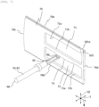
- FIG. 4 is a perspective view showing an appearance of the multi-leaf collimator 60 constituting a part of the radiation irradiation device 24.
- FIG. 5 is a cross-sectional view in a width direction of the multi-leaf collimator 60.
- FIG. 6 is a perspective view showing an outline of a leaf group 70G, in which a plurality of leaves 70 are arranged, of the multi-leaf collimator 60.
- FIG. 7 is a perspective view of one leaf 70.
- the multi-leaf collimator 60 includes a frame 61, the plurality of leaves 70, and driving devices (driving mechanisms) 90.
- the frame 61 is formed in a rectangular parallelepiped shape elongated in one direction.
- the frame 61 is disposed such that a first direction (hereinafter referred to as a width direction W), which is a longitudinal direction of the frame 61, is orthogonal to a radiation irradiation axis Sc of the radiation irradiation device 24.
- the frame 61 is provided with a hollow leaf accommodating portion 62 that is continuous in the width direction W thereof.
- the frame 61 is provided with openings 63 penetrating outer peripheral sides of the frame 61 and the leaf accommodating portion 62 in an upper surface portion 61a on a side facing the radiation irradiation device 24 and a lower surface portion 61b on an opposite side ( FIG. 4 shows only the opening 63 of the upper surface portion 61a). These openings 63 are formed in central portions of the upper surface portion 61a and the lower surface portion 61b in the width direction W.
- rectangular openings 64, 64 are formed in both side surface portions 61c, 61d orthogonal to the upper surface portion 61a and the lower surface portion 61b, respectively.
- the openings 64 in the side surface portion 61c and the openings 64 in the side surface portion 61d are formed to be plane-symmetrical with respect to a virtual plane positioned at a center between the side surface portion 61c and the side surface portion 61d.
- Rectangular base plates 65 are attached to the openings 64, respectively.
- the frame 61 and the base plate 65 may be integrally formed, and the opening 64 may not be formed in the frame 61.
- the leaf 70 is formed in a substantially rectangular thin plate shape.
- the leaf 70 is made of, for example, tungsten, a tungsten alloy, or the like through which the radiation S2 does not pass.
- the leaves 70 are arranged at predetermined intervals in a thickness direction T.
- the plurality of leaves 70 constitute the leaf group 70G.
- the leaf group 70G according to this embodiment includes, for example, thirty leaves 70. As shown in FIGS. 4 and 6 , two sets of such leaf groups 70G are disposed in the leaf accommodating portion 62 in the frame 61 so as to face each other across the radiation irradiation axis Sc (a central portion of the frame 61 in the width direction W).
- the number of leaves 70 in the leaf group 70G is not limited to 30, and can be changed according to performance of the therapy machine, for example.
- an interval between the leaves 70 is shown wider than a thickness T of the leave 70, but actually, the interval between the leaves 70 is smaller than the thickness T of the leave 70.
- FIG. 7 is a perspective view showing the leaf 70 and a driving device 90 that drives the leaf 70.
- the leaf 70 is formed such that a linear upper edge portion (end surface) 70a and a linear lower edge portion 70b are parallel to each other.
- the upper edge portion 70a is disposed to face the upper surface portion 61a with an interval therebetween.
- the lower edge portion 70b is disposed to face the lower surface portion 61b with an interval therebetween.
- the leaf 70 is formed such that a front edge portion 70c on a side facing a central portion of the frame 61 in the width direction W in the leaf accommodating portion 62 bulges in an arc shape.
- a rear edge portion 70d facing an outer side of the frame 61 in the width direction W in the leaf accommodating portion 62 is formed in a linear shape orthogonal to the upper edge portion 70a and the lower edge portion 70b.
- a pair of two groups, namely the leaf groups 70G, 70G disposed to face each other across the central portion in the width direction W in the leaf accommodating portion 62 are disposed such that the front edge portion 70c of each leaf faces a region (region including the radiation irradiation axis Sc) in a space between the opening 63 in the upper surface portion 61a and the opening 63 in the lower surface portion 61b of the frame 61.
- Each leaf 70 includes slits 71, 72 penetrating in the thickness direction T. These slits 71, 72 are formed continuously in a direction in which the front edge portion 70c and the rear edge portion 70d of the leaf 70 are connected, that is, in the width direction W. The slits 71, 72 are formed at an interval in a direction in which the upper edge portion 70a and the lower edge portion 70b of the leaf 70 are connected. These slits 71, 72 are formed at positions shifted to a rear edge portion 70d side from the front edge portion 70c so as not to be irradiated with the radiation S2 incident into the leaf accommodating portion 62 of the frame 61 from the opening 63 of the upper surface portion 61a of the frame 61.
- a rack gear 73 continuous in the width direction W is formed in at least one of upper side portions 71a, 72a and lower side portions 71b, 72b of the slits 71, 72 (72a in FIG. 7 ).
- the driving device 90 includes a motor 91, a shaft 95, and a pinion gear 96.
- the motor 91 is connected to a proximal end portion of the shaft 95.
- the motor 91 rotates the pinion gear 96 by rotationally driving the shaft 95 about an axis thereof.
- the driving devices 90 are respectively provided corresponding to the plurality of leaves 70.
- the shaft 95 of the driving device 90 extends in the plate thickness direction T of the leaf 70.
- the driving device 90 is inserted into the slit 71 or 72 (72 in FIG. 7 ), and the pinion gear 96 is disposed so as to mesh with the rack gear 73. Accordingly, the leaf 70 can be moved in the width direction W by the motor 91 rotating the pinion gear 96.
- the rack gears 73, of the leaves 70, 70 adjacent to each other in a direction in which the plurality of leaves 70 are arranged are formed on sides different from each other of the upper side portions 71a, 72a and the lower side portions 71b, 72b of the slits 71, 72.
- the plurality of leaves 70 constituting each leaf group 70G are supported by the frame 61.
- the frame 61 supports the leaves 70 such that the leaves 70 are movable forward and backward in the width direction W perpendicular to the plate thickness direction T.
- the frame 61 includes a plurality of slide support members 66.
- the plurality of slide support members 66 are disposed at intervals in the width direction W at an upper portion and a lower portion of each leaf group 70G.
- a total of four slide support members 66 that guide movement of the leaves 70 are provided on each of the upper portion and the lower portion of each leaf group 70G, two on a central portion side and two on an outer peripheral side of the frame 61 in the width direction W.
- each slide support member 66 includes a shaft 66a fixed to the frame 61 and a plurality of support rollers 66b rotatably attached to the shaft 66a.
- the plurality of support rollers 66b are disposed at positions respectively corresponding to the plurality of leaves 70 constituting the leaf group 70G.
- the support rollers 66b are rotatable in a direction in which the upper edge portion 70a and the lower edge portion 70b of the leaf 70 extend.
- the leaf 70 is supported by the plurality of support rollers 66b.
- the invention is not limited to this configuration.
- grooves that guide the leaves 70 in a sliding (movement) direction may be formed at positions corresponding to the leaves 70, respectively, and the leaves 70 may be slid.
- each leaf 70 is supported by the frame 61 via the slide support members 66 so as to be individually movable forward and backward in the width direction W.
- the frame 61 is provided with a stopper 68 that restricts a movement amount of each leaf 70 toward the rear edge portion 70d side in the width direction W.
- the motor 91 of the driving device 90 is supported by the base plate 65 provided along each of the side surface portions 61c, 61d of the frame 61.
- a rotary encoder 92 that measures a rotation amount of the shaft 95 is disposed inside the driving device 90.
- the rotary encoder 92 measures the rotation amount of the shaft 95 and outputs the measurement result to the control device 12.
- the therapeutic radiation Sr limited to a predetermined irradiation field shape is generated by the multi-leaf collimator 60.
- each leaf 70 has groove-shaped unevenness whose longitudinal direction is the width W direction on both surfaces.
- the groove-shaped unevenness is formed such that a recess and a protrusion of the adjacent leaves 70 are engaged with each other. This prevents the radiation from reaching the patient B through gaps between the leaves 70 without interfering with the movement of the leaves in the width W direction.
- the multi-leaf collimator 60 has a configuration in which two leaf groups 70G, in each of which the plurality of thin plate-shaped leaves 70 made of a material that does not allow radiation to pass therethrough are arranged in the thickness direction, are arranged such that the end surfaces 70c face each other.
- Main planes of the leaves 70 are arranged so as to be substantially parallel to the radiation irradiation axis Sc.
- the marker 101 containing a phosphor is disposed on an end surface (hereinafter referred to as an upper end surface) 70a of the leaf 70 on a radiation source 50 side.
- Light sources 102a, 102b that irradiate the marker 101 with light for exciting the phosphor, and a camera 103 that captures an image of fluorescence emitted from the marker are disposed at positions where the light sources 102a, 102b and the camera 103 face the upper end surface 70a.
- An optical system such as a mirror 104 and a condenser lens 105 is disposed between the camera 103 and the marker 101 as necessary.
- a plate containing a phosphor is used as the marker 101.
- a plate 101 made of a transparent resin containing a phosphor is used.
- the plate 101 is disposed such that an upper end surface 101a of the plate 101 is located on the upper end surface 70a of the leaf 70.
- One surface of the plate 101 is fixed to one surface of the leaf 70 by adhesion or the like.
- any phosphor may be used as long as the phosphor is excited by visible light or ultraviolet light and emits fluorescence having a wavelength whose image can captured by the camera 103.
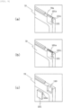
- the upper end surface 101a of the plate 101 may be located on the same plane as the upper end surface 70a of the leaf 70 as shown in (a) of FIG. 8 , may protrude from the upper end surface 70a of the leaf 70 by a predetermined amount as shown in (a) of FIG. 9 , or may be located at a position where the upper end surface 101a is recessed from the upper end surface 70a of the leaf 70 by a predetermined amount as shown in (a) of FIG. 10 .
- a protrusion amount and a recess amount are set in a range in which an image of the upper end surface 101a of the plate 101 can be captured by the camera 103 ((b) of FIG. 8, (b) of FIG. 9, and (b) of FIG. 10 ).
- a recess 110 having a depth (thickness direction T of the leaf) equal to or larger than a thickness of the plate 101 (thickness direction T of the leaf 70) is formed in a surface of the leaf 70 to which the plate 101 is fixed, and the plate 101 is fixed in the recess 110.
- the thickness of the plate 101 is approximately half the thickness of the leaf 70 such that the plates 101 of adjacent leaves can be distinguished by image processing.
- a length of the plate 101 in the width direction W of the leaf 70 is set to a length required when the upper end surface 101a is recognized as a marker by camera image processing.
- a height of the plate 101 (direction of the radiation irradiation axis) is set to a height at which the amount of the phosphor that emits a sufficient amount of fluorescence for the image processing can be ensured, and to a height at which an area capable of obtaining a sufficient adhesive force can be ensured when the plate 101 is bonded to the leaf 70.
- the fluorescence emitted from the upper end surface 101 of the plate 101 is reflected by the mirror 104 as shown in FIG. 11 , is condensed by the condenser lens 105, and reaches the camera 103, whereby an image thereof is captured.
- the control device 12 executes image processing on the image captured by the camera 103, extracts the image of the upper end surface 101a, and detects, for example, a center of the length and width of the image of the upper end surface 101a as a position of the marker (plate 101).
- the control unit 12 determines whether the detected position of the marker 101 corresponds to a rotation amount of the shaft 95 detected by the encoder 92 of the driving device 90. In a case of correspondence, the control unit 12 continues an operation of radiotherapy as it is. In a case of no correspondence, the control unit 12 determines that an error occurs in which a position of the leaf 70 does not correspond to an intended position, and stops radiation irradiation from the radiation source 50.
- a center position of the marker is detected.
- detection is not limited to the center position.
- a position of the marker may be detected by recognizing a center of a short side of a rectangle recognized by four corners of the marker or detected length and width.
- control unit 12 may perform feedback control on the driving device 90 based on the detected position of the marker 101.
- the upper end surface 101a of the plate 101 can be used as a marker by fixing the plate 101, made of the transparent material containing the phosphor, to the surface of the leaf 70 with an adhesive or the like. Accordingly, an adhesion area between the plate 101 and the leaf can be increased, the marker is less likely to peel off, durability is high, a position of the marker can be accurately detected by capturing an image of the marker with the camera, and a position of the leaf can be accurately controlled.
- the amount of the phosphor contained in the plate 101 can be contained to be a necessary amount.
- the fluorescence emitted inside the plate can propagate, and be emitted from the upper end surface 101a. Therefore, since a marker having a large amount of light can be configured, accuracy of marker recognition by image processing can be improved.
- the surfaces of the leaves 70 to which the plates 101 are fixed are surfaces on a side that is shadowed from the camera 103 as shown in (a-1) of FIG. 12 .
- each plate 101 is fixed to a surface on a side far from the optical axis 103a among both surfaces of a respective one of the leaves 70. That is, as shown in (a-1) of FIG. 12 , surfaces of the leaves 70 in the leaf group 70G, to which the plates 101 are fixed, are bilaterally symmetrical with respect to the optical axis 103a in the thickness direction W of the leaves 70.
- an amount of light incident on the plates 101 in which the surfaces 101b parallel to the main planes of the plates 101 are exposed is increased, so that an amount of excitation light is larger than that from the other plates 101 of the leaves 70 in which the surfaces 101b parallel to the main planes of the plates 101 are not exposed. That is, the surfaces 101b parallel to the main planes of the plates 101 are exposed to the outside whatever positions the leaves 70 are located.
- the amount of excitation light emitted from the plates 101 is larger than that of the other plates 101, and a bright marker image is obtained, which may result in reduction in accuracy of binarization processing or the like when processing an image captured by the camera 103. Therefore, it is desirable that at least a part of the surfaces 101b of the plates 101 are covered with light shielding members 140 as shown in (b) of FIG. 14 . However, even if a difference in the amount of the light is generated without covering with the light shielding members, an influence on the reduction in the accuracy of the binarization processing is very small as compared with a case where the side surfaces 101b described above are visible.
- a material that can shield excitation light and external light and is less likely to peel off from the plate 101 is selected as the light shielding member 140.
- the light shielding member (metal film) 140 that can be formed on a surface of the plate 101 by plating, coating, or the like can be used.
- an angle of the side surface may be inclined such that the side surface 101c is shaded by the upper end surface 101a from the camera 103.
- each of both side surfaces 101c, in a movement direction W of the leaf 70, of the plate 101 protruding from the predetermined upper end surface 70a of the leaf 70 by the predetermined amount, is inclined so as to form an acute angle with respect to the upper end surface 101a. Accordingly, as shown in FIG. 11 , even when the leaf 70 moves, the side surface 101c of the protruding portion of the plate 101 is shaded by the upper end surface 101a and is not unintentionally captured by the camera 103. Therefore, since only the upper end surface 101a is recognized as a marker in the movement direction W by the image processing, recognition accuracy of the marker in the movement direction W can be improved.
- upper portions of side surfaces 110a of the recess 110 in the movement direction W is inclined to an angle equal to or larger than a visual angle of the camera 103 so as not to block the visual angle from the camera 103 to entire upper end surface 101a of the plate 101 even when the leaf 70 moves to the maximum movement amount. That is, the side surface 110a is inclined such that a diameter of an opening of the recess 110 in the movement direction W is larger than that of a lower portion of the recess 110. Accordingly, even when the leaf 70 moves, both side surfaces 110a of the recess 110 in the movement direction W does not unintentionally appear in an image captured by the camera 103, and the camera 103 can always capture the image of the entire upper end surface 101a of the plate 101.
- each of both side surfaces 110a, in the movement direction W of the leaf 70, formed by the plate 101 being recessed from the predetermined upper end surface 70a of the leaf 70 by the predetermined amount is inclined so as to form an obtuse angle with respect to the upper end surface 70a. Accordingly, similarly to a case of the plate 101 protruding from the predetermined upper end surface 70a of the leaf 70 by the predetermined amount shown in FIG. 11 , even when the leaf 70 moves, both side surfaces 110a in the movement direction W of the leaf 70 are not shaded by the upper end surface 101a of the plate 101 and are not unintentionally captured by the camera 103. Therefore, since only the upper end surface 101a is recognized in the movement direction W by the image processing, recognition accuracy of the marker in the movement direction W can be improved.
Landscapes
- Health & Medical Sciences (AREA)
- Engineering & Computer Science (AREA)
- Biomedical Technology (AREA)
- Pathology (AREA)
- Nuclear Medicine, Radiotherapy & Molecular Imaging (AREA)
- Radiology & Medical Imaging (AREA)
- Life Sciences & Earth Sciences (AREA)
- Animal Behavior & Ethology (AREA)
- General Health & Medical Sciences (AREA)
- Public Health (AREA)
- Veterinary Medicine (AREA)
- Physics & Mathematics (AREA)
- Spectroscopy & Molecular Physics (AREA)
- General Engineering & Computer Science (AREA)
- High Energy & Nuclear Physics (AREA)
- Radiation-Therapy Devices (AREA)
Abstract
Description
- The present invention relates to a radiotherapy device, and more particularly, to a radiotherapy device including a multi-leaf collimator that limits an irradiation range of radiation to a desired shape.
- Radiotherapy devices that irradiate tumors or the like with radiation are used in clinical practice. A radiotherapy device includes a multi-leaf collimator in order to reduce as much as possible a dose of radiation with which normal tissues around a tumor are irradiated.
- As disclosed in
PTLs 1 to 4, a multi-leaf collimator has a structure in which two groups of stacked bodies are disposed to face each other across an optical axis of radiation. In each stacked body, thin plates made of a material that does not allow the radiation to pass therethrough are arranged in a thickness direction at minute intervals. A direction of a main plane of the thin plate is parallel to the optical axis of the radiation. By moving positions of end surfaces of the thin plates one by one according to a contour of a tumor or a shape of a region to be irradiated with the radiation, an opening having a shape surrounding the tumor can be formed by the two groups of thin plate stacked bodies. This makes it possible to irradiate only the tumor with the radiation. - In order to accurately provide the end surfaces of the thin plate stacked bodies of the multi-leaf collimator at positions corresponding to the contour of the tumor, a marker is disposed on an end surface of each thin plate on an outer side. A position of the marker is detected by capturing an image of the marker with a camera or the like, and the position is used for comparison and determination with a feedback control result of movement of the thin plate.
- In a device according to
PTL 1, ruby is used as the marker, while in devices according toPTLs 2 and 3, paint or the like containing a phosphor is applied as the marker. These markers are irradiated with excitation light, and an image of fluorescence emitted from each of the markers is captured by the camera. -
- PTL 1:
Japanese Patent No. 5143761 - PTL 2:
WO 2015/107651 - PTL 3:
WO 2015/107660 - PTL 4:
WO 2016/121051 - As an example of a method for controlling a thin plate based on a position of a marker in the multi-leaf collimator, a method is used in which a length and a width of the marker are detected by processing an image of the marker captured by the camera, and movement of the thin plate is feedback-controlled such that the position of the marker of the thin plate is located at a desired position, for example, using a center position of the marker as the position of the marker. Therefore, it is important that the length and width of the marker are predetermined sizes.
- In a configuration in which the ruby is used as the marker as in
PTL 1, the ruby has high hardness and is not easily processed, and thus a manufacturing cost increases. -
PTLs 2 and 3 disclose that the marker is formed by applying a fluorescent pigment or a fluorescent paint. - However, when the marker is formed by applying the fluorescent pigment or the fluorescent paint, the marker may be peeled off from the end surface of the thin plate because the marker is a coating film. When a part of the marker is peeled off from the end surface of the thin plate, the length of the marker changes. When a position of the thin plate is detected based on a center of the length of the marker, erroneous position detection is performed.
- In particular, in recent years, thin plates (hereinafter referred to as leaves) of a multi-leaf collimator has been reduced in thickness, and a thickness of the leaves has been reduced to 1 mm or smaller. Markers disposed on end surfaces of the leaves need to be formed such that a width of the markers in a thickness direction of the leaves are approximately half the thickness of the leaves in order to recognize markers of adjacent leaves as separate markers by image processing. Therefore, when the thickness of the leaves is 1 mm or smaller, the width of the markers is 0.5 mm or smaller. It is not easy to apply the fluorescent paint to regions having a width of 0.5 mm or smaller. Since the formed markers have a minute contact area with the end surfaces of the leaves, it is difficult to improve adhesion between the markers and the end surfaces of the leaves, and peeling is likely to occur.
- Since a plurality of leaves are arranged in the thickness direction with gaps smaller than the thickness of the leaves, the width of the markers cannot be made larger than the thickness of the leaves in order to avoid collision between a marker and a leaf adjacent to the marker.
- In order to accurately recognize the length and width of the markers by processing an image captured by a camera, an amount of light emitted from the markers need to be a predetermined amount or more, and the markers need to be formed using a material containing a necessary amount or more of a phosphor.
- An object of the present invention is to accurately detect positions of markers and accurately control positions of leaves by using the markers that are less likely to peel off from end surfaces in a multi-leaf collimator.
- In order to achieve the above object, a radiotherapy device according to the invention includes a radiation source; and a multi-leaf collimator configured to limit an irradiation range of radiation radiated from the radiation source. The multi-leaf collimator includes: a plurality of thin plate-shaped leaves made of a material that does not allow the radiation to pass therethrough, the plurality of thin plate-shaped leaves being arranged in a thickness direction; markers containing a phosphor, the markers being disposed on predetermined end surfaces of the leaves; a light source configured to irradiate the markers with light that excites the phosphor; and a camera configured to capture an image of fluorescence emitted from the markers, the camera being disposed at a position where the camera faces the predetermined end surfaces of the leaves. The markers are plates containing the phosphor, and surfaces of the plates are fixed to surfaces of the leaves such that end surfaces of the plates are located on the predetermined end surfaces of the leaves. An image of the end surfaces of the plates is captured by the camera.
- According to the present invention, since the plates containing the phosphor are inserted in the plurality of leaves and fixed to one of the leaves, and the end surfaces are used as the markers, the markers are less likely to peel off, positions of the markers can be accurately detected by capturing an image of the markers with the camera, and positions of the leaves can be accurately controlled.
-
- [
FIG. 1] FIG. 1 is a block diagram of aradiotherapy system 10 according to an embodiment of the invention. - [
FIG. 2] FIG. 2 is a perspective view of aradiotherapy device 20 according to the embodiment. - [
FIG. 3] FIG. 3 is a cross-sectional view showing a schematic configuration of aradiation irradiation device 24 in theradiotherapy device 20 inFIG. 2 . - [
FIG. 4] FIG. 4 is a perspective view of a multi-leaf collimator of theradiation irradiation device 24 inFIG. 3 . - [
FIG. 5] FIG. 5 is a cross-sectional view of the multi-leaf collimator inFIG. 4 . - [
FIG. 6] FIG. 6 is a perspective view showing a configuration example of aleaf group 70G of the multi-leaf collimator inFIG. 4 . - [
FIG. 7] FIG. 7 is a perspective view of aleaf 70 and adriving device 90 of the multi-leaf collimator inFIG. 4 . - [
FIG. 8 ] (a) ofFIG. 8 is an enlarged perspective view of aplate 101 portion of theleaf 70 inFIG. 7 , (b) ofFIG. 8 is an explanatory view showing anupper end surface 101a recognized as a marker, and (c) ofFIG. 8 is an enlarged perspective view showing arecess 110 for fixing theplate 101 to theleaf 70, and theplate 110. - [
FIG. 9 ] (a) ofFIG. 9 is an enlarged perspective view of theplate 101 portion of theleaf 70 inFIG. 7 , (b) ofFIG. 9 is an explanatory view showing theupper end surface 101a recognized as a marker, and (c) ofFIG. 9 is an enlarged perspective view showing therecess 110 for fixing theplate 101 to theleaf 70, and theplate 110. - [
FIG. 10 ] (a) ofFIG. 10 is an enlarged perspective view of theplate 101 portion of theleaf 70 inFIG. 7 , (b) ofFIG. 10 is an explanatory view showing theupper end surface 101a recognized as a marker, and (c) ofFIG. 10 is an enlarged perspective view showing therecess 110 for fixing theplate 101 to theleaf 70, and theplate 110. - [
FIG. 11] FIG. 11 is an explanatory view showing an image of a range of a position of theplate 101 captured by acamera 103 according to the embodiment. - [
FIG. 12 ] (a-1) and (a-2) ofFIG. 12 are an explanatory view showing an example in which theplates 101 are disposed on surfaces of theleaves 70 on an outer side with respect to anoptical axis 103a according to the embodiment and an explanatory view showing an image example of thecamera 103 at that time, and (b-1) and (b-2) ofFIG. 12 are an explanatory view showing an example in which theplates 101 are disposed on surfaces of theleaves 70 on the same side according to the embodiment and an explanatory view showing an image example of thecamera 103 at that time. - [
FIG. 13] FIG. 13 is a perspective view showing that an image ofsurfaces 101b of theplates 101 is captured by thecamera 103 in arrangement in (b-1) ofFIG. 12 . - [
FIG. 14 ] (a) ofFIG. 14 is a perspective view showing a state in which thesurfaces 101b of theplates 101 are exposed in arrangement in (a-1) ofFIG. 12 , and (b) ofFIG. 14 is a perspective view showing a state in whichlight shielding members 140 are disposed on thesurfaces 101b of theplates 101. - [
FIG. 15 ] (a), (b-1), and (c) ofFIG. 15 are explanatory views that aside surface 101c is unintentionally captured by the camera when theupper end surface 101a of theplate 101 according to the embodiment is disposed so as to protrude from a predeterminedupper end surface 70a of theleaf 70 by a predetermined amount, and (b-2) ofFIG. 15 is an explanatory view showing a shape in which theside surface 101c of theplate 101 according to the embodiment is formed at an acute angle with respect to the upper end surface. - A radiotherapy system according to an embodiment of the invention will be described.
- First, an overall configuration of the radiotherapy system according to the present embodiment will be described.
-
FIG. 1 is a diagram showing a functional configuration of aradiotherapy system 10 according to the embodiment of the invention. - As shown in
FIG. 1 , theradiotherapy system 10 includes atherapy planning device 11, a control device (control unit) 12, and aradiotherapy device 20. - The
therapy planning device 11 is a device that receives, from the outside, properties of radiation to be radiated to a patient B (intensity, time, angle, position, radiation region, and the like of radiation radiated to the patient B), which is set in advance according to a content of radiotherapy to be performed on the patient B. Thetherapy planning device 11 outputs, to thecontrol device 12, various control parameter values for radiating radiation corresponding to the received properties of the radiation. - The
control device 12 controls an operation of theradiotherapy device 20 based on the various parameter values generated by thetherapy planning device 11. Thecontrol device 12 is a computer device such as a personal computer that executes processing based on a predetermined program. Thecontrol device 12 is connected to theradiotherapy device 20 wirelessly or via a wired communication line such that information can be transmitted bidirectionally. -
FIG. 2 is a perspective view showing a schematic configuration of theradiotherapy device 20 constituting theradiotherapy system 10. - As shown in
FIG. 2 , theradiotherapy device 20 includes aring frame 21, a movinggantry 22, and aradiation irradiation device 24. - The
ring frame 21 is formed in a cylindrical shape having a circular cross section. Thering frame 21 is disposed such that a central axis C1 is oriented substantially in a horizontal direction. Arotation shaft 25 extending downward is integrally formed on an outer peripheral surface of alower end portion 21a of thering frame 21. Therotation shaft 25 is supported by a base (not shown) so as to be rotatable about a central axis C2 thereof. Therotation shaft 25 is rotationally driven by a turning driving mechanism (not shown). That is, thering frame 21 turns around a vertical axis as therotation shaft 25 is rotated by the turning driving mechanism. - The moving
gantry 22 is formed in a cylindrical shape having a circular cross section. The movinggantry 22 is disposed on an inner circumferential side of thering frame 21. The movinggantry 22 is supported by thering frame 21 and is rotatable along an inner circumferential surface of thering frame 21. In other words, the annular movinggantry 22 is rotatable about the central axis C1 extending in the horizontal direction. The movinggantry 22 is rotated in a circumferential direction by a gantry driving mechanism (not shown). - The
radiation irradiation device 24 is controlled by the control device 12 (seeFIG. 1 ) to radiate therapeutic radiation Sr. Theradiation irradiation device 24 is supported by an innercircumferential surface 22a of the movinggantry 22. The therapeutic radiation Sr radiated from theradiation irradiation device 24 is adjusted so as to pass through an isocenter C0, which is an intersection of the central axis C2 of a rotation operation of thering frame 21 and the central axis C1 of a rotation operation of the movinggantry 22. - Since the
radiation irradiation device 24 is supported by the movinggantry 22 in this way, the therapeutic radiation Sr is radiated so as to always pass through the isocenter C0 regardless of the rotation operation of thering frame 21 about the central axis C2 and the rotation operation of the movinggantry 22 about the central axis C1. - The
radiotherapy device 20 further includes asensor array 23. Thesensor array 23 receives the therapeutic radiation Sr radiated by theradiation irradiation device 24 and transmitted through a subject around the isocenter C0, and generates a transmission image of the subject. A flat panel detector (FPD), an X-ray image intensifier (II), or the like can be used as thesensor array 23. - The
radiotherapy device 20 includesdiagnostic X-ray sources sensor arrays 27A, 27B. - The
diagnostic X-ray sources gantry 22. Thediagnostic X-ray sources ring frame 21 in the circumferential direction across a center of the radiotherapy device 20 (in other words, the central axis C2 of the rotation operation of the ring frame 21). Thediagnostic X-ray sources control device 12 to radiatediagnostic X-rays 101 toward the isocenter C0. Thediagnostic X-rays 101 form a conical beam that spreads in a conical shape from one point of each of thediagnostic X-ray sources - The
sensor arrays 27A, 27B are supported by the innercircumferential surface 22a of the movinggantry 22. Thesensor arrays 27A, 27B are disposed so as to face thediagnostic X-ray sources sensor arrays 27A, 27B receive thediagnostic X-rays 101 radiated from thediagnostic X-ray sources sensor arrays 27A, 27B. - The
radiotherapy device 20 further includes acouch 28 and acouch driving device 29. Thecouch 28 includes anupper surface 28a on which the patient B to be treated by theradiotherapy system 10 lies horizontally. - The
couch driving device 29 is controlled by thecontrol device 12 to move thecouch 28. Thecouch driving device 29 is supported by a base (not shown). -
FIG. 3 is a cross-sectional view showing theradiation irradiation device 24 constituting theradiotherapy device 20. - As shown in
FIG. 3 , theradiation irradiation device 24 includes aradiation source 50, aprimary collimator 53, a flatteningfilter 54, asecondary collimator 55, and amulti-leaf collimator 60. Here, theradiation source 50 is an X-ray source including anelectron beam accelerator 51 and anX-ray target 52. - The
electron beam accelerator 51 irradiates theX-ray target 52 with an electron beam S0 generated by accelerating electrons. - The
X-ray target 52 is made of tungsten, a tungsten alloy, or the like. TheX-ray target 52 radiates radiation S1 when irradiated with the electron beam S0. - The
primary collimator 53 shields a part of the radiation S1 such that the radiation S1 is not radiated to a portion other than a desired portion. Theprimary collimator 53 includes a throughhole 53h through which the radiation S1 radiated from theX-ray target 52 passes. Theprimary collimator 53 is made of lead, tungsten, or the like. - The flattening
filter 54 is a filter that distributes a dose of the radiation S1 substantially uniformly in a plane perpendicular to a radiation direction of the radiation S1. The flatteningfilter 54 is made of aluminum or the like. The flatteningfilter 54 is disposed on an outlet side of the throughhole 53h of theprimary collimator 53. The flatteningfilter 54 has a substantiallyconical protrusion 54a on a side facing theX-ray target 52. A shape of theprotrusion 54a is designed such that the dose of the radiation S1 is substantially uniformly distributed in the plane perpendicular to the radiation direction of the radiation S1. - The
secondary collimator 55 shields a part of the radiation S1. Thesecondary collimator 55 has a throughhole 55h at a central portion thereof. Thesecondary collimator 55 allows radiation S2 to pass through only the throughhole 55h. Thesecondary collimator 55 is made of lead, tungsten, or the like. - By passing through the
primary collimator 53, the flatteningfilter 54, and thesecondary collimator 55 described above, a part of the radiation S2 having a uniform intensity distribution is further shielded by themulti-leaf collimator 60. Themulti-leaf collimator 60 is controlled by thecontrol device 12 to limit an irradiation field of the radiation S2. Themulti-leaf collimator 60 generates therapeutic radiation Sr according to the properties of the radiation to be radiated to the patient. - Hereinafter, a configuration of the multi-leaf collimator will be described in more detail.
-
FIG. 4 is a perspective view showing an appearance of themulti-leaf collimator 60 constituting a part of theradiation irradiation device 24.FIG. 5 is a cross-sectional view in a width direction of themulti-leaf collimator 60.FIG. 6 is a perspective view showing an outline of aleaf group 70G, in which a plurality ofleaves 70 are arranged, of themulti-leaf collimator 60.FIG. 7 is a perspective view of oneleaf 70. - As shown in
FIGS. 4 to 7 , themulti-leaf collimator 60 includes aframe 61, the plurality ofleaves 70, and driving devices (driving mechanisms) 90. - The
frame 61 is formed in a rectangular parallelepiped shape elongated in one direction. Theframe 61 is disposed such that a first direction (hereinafter referred to as a width direction W), which is a longitudinal direction of theframe 61, is orthogonal to a radiation irradiation axis Sc of theradiation irradiation device 24. Theframe 61 is provided with a hollow leafaccommodating portion 62 that is continuous in the width direction W thereof. - The
frame 61 is provided withopenings 63 penetrating outer peripheral sides of theframe 61 and theleaf accommodating portion 62 in anupper surface portion 61a on a side facing theradiation irradiation device 24 and alower surface portion 61b on an opposite side (FIG. 4 shows only theopening 63 of theupper surface portion 61a). Theseopenings 63 are formed in central portions of theupper surface portion 61a and thelower surface portion 61b in the width direction W. - As shown in
FIGS. 4 and5 , in theframe 61,rectangular openings side surface portions 61c, 61d orthogonal to theupper surface portion 61a and thelower surface portion 61b, respectively. Theopenings 64 in theside surface portion 61c and theopenings 64 in the side surface portion 61d are formed to be plane-symmetrical with respect to a virtual plane positioned at a center between theside surface portion 61c and the side surface portion 61d.Rectangular base plates 65 are attached to theopenings 64, respectively. In this embodiment, a case where theopening 64 is formed in theframe 61 and thebase plate 65 is attached is illustrated. However, the invention is not limited to this configuration. For example, theframe 61 and thebase plate 65 may be integrally formed, and theopening 64 may not be formed in theframe 61. - The
leaf 70 is formed in a substantially rectangular thin plate shape. Theleaf 70 is made of, for example, tungsten, a tungsten alloy, or the like through which the radiation S2 does not pass. - As shown in
FIGS. 5 and6 , theleaves 70 are arranged at predetermined intervals in a thickness direction T. The plurality ofleaves 70 constitute theleaf group 70G. Theleaf group 70G according to this embodiment includes, for example, thirty leaves 70. As shown inFIGS. 4 and6 , two sets ofsuch leaf groups 70G are disposed in theleaf accommodating portion 62 in theframe 61 so as to face each other across the radiation irradiation axis Sc (a central portion of theframe 61 in the width direction W). The number ofleaves 70 in theleaf group 70G is not limited to 30, and can be changed according to performance of the therapy machine, for example. - In
FIG. 6 , for convenience of illustration, an interval between theleaves 70 is shown wider than a thickness T of theleave 70, but actually, the interval between theleaves 70 is smaller than the thickness T of theleave 70. -
FIG. 7 is a perspective view showing theleaf 70 and adriving device 90 that drives theleaf 70. - As shown in
FIG. 7 , theleaf 70 is formed such that a linear upper edge portion (end surface) 70a and a linearlower edge portion 70b are parallel to each other. As shown inFIG. 5 , in theleaf accommodating portion 62, theupper edge portion 70a is disposed to face theupper surface portion 61a with an interval therebetween. Similarly, in theleaf accommodating portion 62, thelower edge portion 70b is disposed to face thelower surface portion 61b with an interval therebetween. - The
leaf 70 is formed such that afront edge portion 70c on a side facing a central portion of theframe 61 in the width direction W in theleaf accommodating portion 62 bulges in an arc shape. In theleaf 70, arear edge portion 70d facing an outer side of theframe 61 in the width direction W in theleaf accommodating portion 62 is formed in a linear shape orthogonal to theupper edge portion 70a and thelower edge portion 70b. - A pair of two groups, namely the
leaf groups leaf accommodating portion 62 are disposed such that thefront edge portion 70c of each leaf faces a region (region including the radiation irradiation axis Sc) in a space between the opening 63 in theupper surface portion 61a and theopening 63 in thelower surface portion 61b of theframe 61. - Each
leaf 70 includesslits slits front edge portion 70c and therear edge portion 70d of theleaf 70 are connected, that is, in the width direction W. Theslits upper edge portion 70a and thelower edge portion 70b of theleaf 70 are connected. Theseslits rear edge portion 70d side from thefront edge portion 70c so as not to be irradiated with the radiation S2 incident into theleaf accommodating portion 62 of theframe 61 from theopening 63 of theupper surface portion 61a of theframe 61. - In each
leaf 70, arack gear 73 continuous in the width direction W is formed in at least one ofupper side portions lower side portions slits 71, 72 (72a inFIG. 7 ). - The driving
device 90 includes a motor 91, ashaft 95, and apinion gear 96. The motor 91 is connected to a proximal end portion of theshaft 95. The motor 91 rotates thepinion gear 96 by rotationally driving theshaft 95 about an axis thereof. - The driving
devices 90 are respectively provided corresponding to the plurality ofleaves 70. - As shown in
FIG. 7 , theshaft 95 of the drivingdevice 90 extends in the plate thickness direction T of theleaf 70. The drivingdevice 90 is inserted into theslit 71 or 72 (72 inFIG. 7 ), and thepinion gear 96 is disposed so as to mesh with therack gear 73. Accordingly, theleaf 70 can be moved in the width direction W by the motor 91 rotating thepinion gear 96. - Here, in the
leaf group 70G according to this embodiment, the rack gears 73, of theleaves leaves 70 are arranged, are formed on sides different from each other of theupper side portions lower side portions slits pinion gear 96 meshing with therack gear 73 from interfering between theleaves - The plurality of
leaves 70 constituting eachleaf group 70G are supported by theframe 61. Theframe 61 supports theleaves 70 such that theleaves 70 are movable forward and backward in the width direction W perpendicular to the plate thickness direction T. Theframe 61 includes a plurality ofslide support members 66. The plurality ofslide support members 66 are disposed at intervals in the width direction W at an upper portion and a lower portion of eachleaf group 70G. In this embodiment, a total of fourslide support members 66 that guide movement of theleaves 70 are provided on each of the upper portion and the lower portion of eachleaf group 70G, two on a central portion side and two on an outer peripheral side of theframe 61 in the width direction W. - As shown in
FIG. 5 , eachslide support member 66 includes ashaft 66a fixed to theframe 61 and a plurality ofsupport rollers 66b rotatably attached to theshaft 66a. The plurality ofsupport rollers 66b are disposed at positions respectively corresponding to the plurality ofleaves 70 constituting theleaf group 70G. Thesupport rollers 66b are rotatable in a direction in which theupper edge portion 70a and thelower edge portion 70b of theleaf 70 extend. In this embodiment, theleaf 70 is supported by the plurality ofsupport rollers 66b. However, the invention is not limited to this configuration. For example, grooves that guide theleaves 70 in a sliding (movement) direction may be formed at positions corresponding to theleaves 70, respectively, and theleaves 70 may be slid. - That is, each
leaf 70 is supported by theframe 61 via theslide support members 66 so as to be individually movable forward and backward in the width direction W. - The
frame 61 is provided with astopper 68 that restricts a movement amount of eachleaf 70 toward therear edge portion 70d side in the width direction W. - As shown in
FIG. 4 , the motor 91 of the drivingdevice 90 is supported by thebase plate 65 provided along each of theside surface portions 61c, 61d of theframe 61. - A rotary encoder 92 that measures a rotation amount of the
shaft 95 is disposed inside the drivingdevice 90. The rotary encoder 92 measures the rotation amount of theshaft 95 and outputs the measurement result to thecontrol device 12. - In this way, in the pair of two
leaf groups 70G, by advancing and retreating the end surfaces 70c of theleaves 70 constituting theleaf groups 70G in the width direction W to positions corresponding to a desired irradiation field contour shape, an opening having a desired irradiation field shape can be formed between theleaves 70 of theleaf groups 70G facing each other. - Therefore, when the radiation S2 is made incident from the
opening 63 in theupper surface portion 61a of theframe 61, a part of the radiation is shielded by theleaves 70 of theleaf groups 70G on both sides, and the patient B is irradiated with the radiation that has passed through the opening formed by theleaf groups 70G. - That is, the therapeutic radiation Sr limited to a predetermined irradiation field shape is generated by the
multi-leaf collimator 60. - Although not shown in
FIGS. 6 and7 , eachleaf 70 has groove-shaped unevenness whose longitudinal direction is the width W direction on both surfaces. The groove-shaped unevenness is formed such that a recess and a protrusion of the adjacent leaves 70 are engaged with each other. This prevents the radiation from reaching the patient B through gaps between theleaves 70 without interfering with the movement of the leaves in the width W direction. - Hereinafter, a configuration of a
marker 101 fixed to theleaf 70 of themulti-leaf collimator 60 will be described with reference toFIGS. 6 and7 . - As described above, the
multi-leaf collimator 60 has a configuration in which twoleaf groups 70G, in each of which the plurality of thin plate-shapedleaves 70 made of a material that does not allow radiation to pass therethrough are arranged in the thickness direction, are arranged such that the end surfaces 70c face each other. Main planes of theleaves 70 are arranged so as to be substantially parallel to the radiation irradiation axis Sc. - The
marker 101 containing a phosphor is disposed on an end surface (hereinafter referred to as an upper end surface) 70a of theleaf 70 on aradiation source 50 side.Light sources marker 101 with light for exciting the phosphor, and acamera 103 that captures an image of fluorescence emitted from the marker are disposed at positions where thelight sources camera 103 face theupper end surface 70a. An optical system such as amirror 104 and acondenser lens 105 is disposed between thecamera 103 and themarker 101 as necessary. - In the present embodiment, a plate containing a phosphor is used as the
marker 101. For example, aplate 101 made of a transparent resin containing a phosphor is used. - As shown in
FIGS. 6 and7 , theplate 101 is disposed such that anupper end surface 101a of theplate 101 is located on theupper end surface 70a of theleaf 70. - One surface of the
plate 101 is fixed to one surface of theleaf 70 by adhesion or the like. - As the phosphor (fluorescent pigment), any phosphor may be used as long as the phosphor is excited by visible light or ultraviolet light and emits fluorescence having a wavelength whose image can captured by the
camera 103. - The
upper end surface 101a of theplate 101 may be located on the same plane as theupper end surface 70a of theleaf 70 as shown in (a) ofFIG. 8 , may protrude from theupper end surface 70a of theleaf 70 by a predetermined amount as shown in (a) ofFIG. 9 , or may be located at a position where theupper end surface 101a is recessed from theupper end surface 70a of theleaf 70 by a predetermined amount as shown in (a) ofFIG. 10 . - However, a protrusion amount and a recess amount are set in a range in which an image of the
upper end surface 101a of theplate 101 can be captured by the camera 103 ((b) ofFIG. 8, (b) ofFIG. 9, and (b) ofFIG. 10 ). - At this time, it is desirable that a
recess 110 having a depth (thickness direction T of the leaf) equal to or larger than a thickness of the plate 101 (thickness direction T of the leaf 70) is formed in a surface of theleaf 70 to which theplate 101 is fixed, and theplate 101 is fixed in therecess 110. By providing therecess 110, even if the thickness of theplate 101 is ensured to some extent, theplate 101 does not come into contact with theleaf 70 adjacent to the fixedleaf 70, and thus theplate 101 does not interfere with the movement of theleaves 70 while ensuring an amount of the phosphor contained in theplate 101. - It is desirable that the thickness of the
plate 101 is approximately half the thickness of theleaf 70 such that theplates 101 of adjacent leaves can be distinguished by image processing. - A length of the
plate 101 in the width direction W of theleaf 70 is set to a length required when theupper end surface 101a is recognized as a marker by camera image processing. - A height of the plate 101 (direction of the radiation irradiation axis) is set to a height at which the amount of the phosphor that emits a sufficient amount of fluorescence for the image processing can be ensured, and to a height at which an area capable of obtaining a sufficient adhesive force can be ensured when the
plate 101 is bonded to theleaf 70. - In such a configuration, light emitted from the
light sources upper end surface 101a of theplate 101. Since theplate 101 is made of a transparent material containing a phosphor, the light emitted from thelight sources plate 101 to excite the phosphor. Accordingly, fluorescence is generated not only from theupper end surface 101a of theplate 101 but also from the phosphor inside theplate 101. The fluorescence generated inside theplate 101 propagates through theplate 101, reaches theupper end surface 101a, and is emitted upward from theupper end surface 101a. - The fluorescence emitted from the
upper end surface 101 of theplate 101 is reflected by themirror 104 as shown inFIG. 11 , is condensed by thecondenser lens 105, and reaches thecamera 103, whereby an image thereof is captured. - The
control device 12 executes image processing on the image captured by thecamera 103, extracts the image of theupper end surface 101a, and detects, for example, a center of the length and width of the image of theupper end surface 101a as a position of the marker (plate 101). Thecontrol unit 12 determines whether the detected position of themarker 101 corresponds to a rotation amount of theshaft 95 detected by the encoder 92 of the drivingdevice 90. In a case of correspondence, thecontrol unit 12 continues an operation of radiotherapy as it is. In a case of no correspondence, thecontrol unit 12 determines that an error occurs in which a position of theleaf 70 does not correspond to an intended position, and stops radiation irradiation from theradiation source 50. - In this embodiment, a center position of the marker is detected. However, detection is not limited to the center position. For example, a position of the marker may be detected by recognizing a center of a short side of a rectangle recognized by four corners of the marker or detected length and width.
- Alternatively, the
control unit 12 may perform feedback control on the drivingdevice 90 based on the detected position of themarker 101. - In this way, in the present embodiment, the
upper end surface 101a of theplate 101 can be used as a marker by fixing theplate 101, made of the transparent material containing the phosphor, to the surface of theleaf 70 with an adhesive or the like. Accordingly, an adhesion area between theplate 101 and the leaf can be increased, the marker is less likely to peel off, durability is high, a position of the marker can be accurately detected by capturing an image of the marker with the camera, and a position of the leaf can be accurately controlled. - Since the height of the plate 101 (size in the direction of the radiation irradiation axis) can be increased, the amount of the phosphor contained in the
plate 101 can be contained to be a necessary amount. The fluorescence emitted inside the plate can propagate, and be emitted from theupper end surface 101a. Therefore, since a marker having a large amount of light can be configured, accuracy of marker recognition by image processing can be improved. - It is desirable that the surfaces of the
leaves 70 to which theplates 101 are fixed are surfaces on a side that is shadowed from thecamera 103 as shown in (a-1) ofFIG. 12 . For example, when anoptical axis 103a of thecamera 103 is located at a center of theleaf group 70G in which the plurality ofleaves 70 are arranged in the thickness direction as shown in (a-1) ofFIG. 12 , it is desirable that eachplate 101 is fixed to a surface on a side far from the optical axis 103a among both surfaces of a respective one of theleaves 70. That is, as shown in (a-1) ofFIG. 12 , surfaces of theleaves 70 in theleaf group 70G, to which theplates 101 are fixed, are bilaterally symmetrical with respect to theoptical axis 103a in the thickness direction W of theleaves 70. - Accordingly, when the upper end surfaces 101a of the
plates 101 do not protrude from the upper end surfaces 70a of theleaves 70,surfaces 101b parallel to main planes of theplate 101 are not unintentionally captured by thecamera 103. Therefore, a width of only theupper end surfaces 101a recognized as the markers in image processing can be extracted, and the image processing can be performed with high accuracy. - Even when the upper end surfaces 101a of the
plates 101 protrude from the upper end surfaces 70a of theleaves 70 by a predetermined amount, in a case where theplates 101 are fixed to the surfaces on the side far from theoptical axis 103a as shown in (a-1) ofFIG. 12 , thesurfaces 101b parallel to the main planes of theplates 101 as shown in (a-2) ofFIG. 12 have only small protruding portions unintentionally captured by thecamera 103, and an influence on the width of theupper end surfaces 101a recognized as the markers in the image processing is small. - In contrast, when the
plates 101 are fixed to surfaces on the same side of all theleaves 70 in theleaf group 70G as shown in (b-1) ofFIG. 12 , an area of thesurfaces 101b parallel to the main planes of theplates 101 unintentionally captured by thecamera 103 as shown in (b-2) ofFIG. 12 is larger than that in (a-2) ofFIG. 12 . Therefore, not only an image of the upper end surfaces 101a of theplates 101 but also an image of thesurfaces 101b are recognized as the markers by the image processing, so that accuracy of the markers in a width direction is lower than that in a case of (a-2) ofFIG. 12 . - When the
plates 101 are fixed to surfaces on the same side of all theleaves 70 in theleaf group 70G as shown in (b-1) ofFIG. 12 , in a case where positions ofadjacent leaves 70 are largely shifted as shown inFIG. 13 , an image of theentire surface 101b parallel to the main plane of theplate 101 is captured by thecamera 103. In this case, since a width of a marker recognized by the image processing includes theentire surface 101b, accuracy of the marker in the width direction is lower than that in the case of (a-2) ofFIG. 12 . Therefore, it is desirable that the surfaces of theleaves 70 to which theplates 101 are fixed are the surfaces on the side that is shadowed from thecamera 103 as shown in (a-1) ofFIG. 12 . - Even when the surfaces of the
leaves 70 to which theplates 101 are fixed are the surfaces on the side that is shadowed from thecamera 103 as shown in (a-1) ofFIG. 12 (that is, when theplates 101 are fixed to the surfaces on the side far from the optical axis 103a), in a case where the positions of theleaves 70 are largely shifted and theplates 101 fixed to theleave 70 include, in a mixed manner, ones in which thesurfaces 101b parallel to the main planes of theplates 101 are exposed to the outside and ones in which thesurfaces 101b are not exposed to the outside as shown in (a) ofFIG. 14 , an amount of light incident on theplates 101 in which thesurfaces 101b parallel to the main planes of theplates 101 are exposed is increased, so that an amount of excitation light is larger than that from theother plates 101 of theleaves 70 in which thesurfaces 101b parallel to the main planes of theplates 101 are not exposed. That is, thesurfaces 101b parallel to the main planes of theplates 101 are exposed to the outside whatever positions theleaves 70 are located. - Therefore, in these
plates 101, the amount of excitation light emitted from theplates 101 is larger than that of theother plates 101, and a bright marker image is obtained, which may result in reduction in accuracy of binarization processing or the like when processing an image captured by thecamera 103. Therefore, it is desirable that at least a part of thesurfaces 101b of theplates 101 are covered withlight shielding members 140 as shown in (b) ofFIG. 14 . However, even if a difference in the amount of the light is generated without covering with the light shielding members, an influence on the reduction in the accuracy of the binarization processing is very small as compared with a case where the side surfaces 101b described above are visible. - A material that can shield excitation light and external light and is less likely to peel off from the
plate 101 is selected as thelight shielding member 140. For example, the light shielding member (metal film) 140 that can be formed on a surface of theplate 101 by plating, coating, or the like can be used. - When the
upper end surface 101a of theplate 101 is disposed so as to protrude from the predeterminedupper end surface 70a of theleaf 70 by the predetermined amount as inFIG. 9 described above, aside surface 101c of a portion of theplate 101 protruding from theleaf 70 as in (a) and (b-1) ofFIG. 15 unintentionally appears an image captured by the camera 103 ((c) ofFIG. 15 ). In order to solve this problem, an angle of the side surface may be inclined such that theside surface 101c is shaded by theupper end surface 101a from thecamera 103. - For example, as shown in (a) to (c) of
FIG. 9 and (b-2) ofFIG. 15 , each of bothside surfaces 101c, in a movement direction W of theleaf 70, of theplate 101 protruding from the predeterminedupper end surface 70a of theleaf 70 by the predetermined amount, is inclined so as to form an acute angle with respect to theupper end surface 101a. Accordingly, as shown inFIG. 11 , even when theleaf 70 moves, theside surface 101c of the protruding portion of theplate 101 is shaded by theupper end surface 101a and is not unintentionally captured by thecamera 103. Therefore, since only theupper end surface 101a is recognized as a marker in the movement direction W by the image processing, recognition accuracy of the marker in the movement direction W can be improved. - Similarly, when the
upper end surface 101a of theplate 101 is disposed so as to be recessed from the predeterminedupper end surface 70a of theleaf 70 by the predetermined amount as shown inFIG. 10 described above, if theleaf 70 moves in the movement direction W, a positional relationship is formed in which thecamera 103 views theupper end surface 101a of the plate recessed in therecess 110 from obliquely above theupper end surface 101a of theplate 101. At this time, an edge portion of therecess 110 in the movement direction W direction partially blocks an angle at which thecamera 103 views the entireupper end surface 101a of theplate 101, and thecamera 103 cannot capture an image of the entire recessedupper end surface 101a of theplate 101. Therefore, in the present embodiment, upper portions ofside surfaces 110a of therecess 110 in the movement direction W is inclined to an angle equal to or larger than a visual angle of thecamera 103 so as not to block the visual angle from thecamera 103 to entireupper end surface 101a of theplate 101 even when theleaf 70 moves to the maximum movement amount. That is, theside surface 110a is inclined such that a diameter of an opening of therecess 110 in the movement direction W is larger than that of a lower portion of therecess 110. Accordingly, even when theleaf 70 moves, bothside surfaces 110a of therecess 110 in the movement direction W does not unintentionally appear in an image captured by thecamera 103, and thecamera 103 can always capture the image of the entireupper end surface 101a of theplate 101. - For example, as shown in (c) of
FIG. 10 , each of bothside surfaces 110a, in the movement direction W of theleaf 70, formed by theplate 101 being recessed from the predeterminedupper end surface 70a of theleaf 70 by the predetermined amount, is inclined so as to form an obtuse angle with respect to theupper end surface 70a. Accordingly, similarly to a case of theplate 101 protruding from the predeterminedupper end surface 70a of theleaf 70 by the predetermined amount shown inFIG. 11 , even when theleaf 70 moves, bothside surfaces 110a in the movement direction W of theleaf 70 are not shaded by theupper end surface 101a of theplate 101 and are not unintentionally captured by thecamera 103. Therefore, since only theupper end surface 101a is recognized in the movement direction W by the image processing, recognition accuracy of the marker in the movement direction W can be improved. -
- 10 radiotherapy system
- 11 therapy planning device
- 12 control device
- 20 radiotherapy device
- 21 ring frame
- 21a lower end portion
- 22 moving gantry
- 22a inner circumferential surface
- 23 sensor array
- 24 radiation irradiation device
- 25 rotation shaft
- 26A, 26B ray source
- 27A, 27B sensor array
- 28 couch
- 28a upper surface
- 29 couch driving device
- 50 radiation source
- 51 electron beam accelerator
- 52 X-ray target
- 53 primary collimator
- 53h through hole
- 54 flattening filter
- 54a protrusion
- 55 secondary collimator
- 55h through hole
- 60 multi-leaf collimator
- 61 frame
- 61a upper surface portion
- 61b lower surface portion
- 61c, 61d side surface portion
- 62 leaf accommodating portion
- 63 opening
- 64 opening
- 65 base plate
- 66 slide support member
- 66a shaft
- 66b support roller
- 68 stopper
- 70 leaf
- 70G leaf group
- 70a upper edge portion
- 70b lower edge portion
- 70c front edge portion
- 70d rear edge portion
- 70f surface
- 70g surface
- 71, 72 slit
- 71a, 72a upper side portion
- 71b lower side portion
- 73 rack gear
- 90 driving device
- 91 motor
- 91a housing
- 92 rotary encoder
- 95 shaft
- 96 pinion gear
- 101 plate
- 101a end surface (upper end surface)
- 101b surface (surface parallel to main plane)
- 101c side surface (side surface in movement direction W)
- 110 recess
- B patient
- C0 isocenter
- C1 central axis
- C2 central axis
- S0 electron beam
- S1 radiation
- S2 radiation
- Sr therapeutic radiation
- T plate thickness direction
- W width (movement) direction
Claims (13)
- A radiotherapy device comprising:a radiation source; anda multi-leaf collimator configured to limit an irradiation range of radiation radiated from the radiation source, whereinthe multi-leaf collimator includes:a plurality of thin plate-shaped leaves made of a material that does not allow the radiation to pass therethrough, the plurality of thin plate-shaped leaves being arranged in a thickness direction;markers containing a phosphor, the markers being disposed on predetermined end surfaces of the leaves;a light source configured to irradiate the markers with light that excites the phosphor; anda camera configured to capture an image of fluorescence emitted from the markers, the camera being disposed at a position where the camera faces the predetermined end surfaces of the leaves, andthe markers are plates containing the phosphor, surfaces of the plates are fixed to surfaces of the leaves such that end surfaces of the plates are located on the predetermined end surfaces of the leaves, and an image of the end surfaces of the plates is captured by the camera.
- The radiotherapy device according to claim 1, wherein
the end surfaces of the plates protrude from the predetermined end surfaces of the leaves by a predetermined amount. - The radiotherapy device according to claim 1, wherein
the end surfaces of the plates are located at positions where the end surfaces of the plates are recessed from the predetermined end surfaces of the leaves by a predetermined amount. - The radiotherapy device according to claim 1, wherein
recesses having a depth equal to or larger than a thickness of the plates are formed in the surfaces of the leaves to which the plates are fixed, and the plates are fixed in the recesses. - The radiotherapy device according to claim 1, wherein
the surfaces of the leaves to which the plates are fixed are surfaces on a side that is shadowed from the camera. - The radiotherapy device according to claim 1, wherein
at least a part of surfaces of the plates fixed to the leaves are covered with a light shielding member on a side not fixed to the leaves. - The radiotherapy device according to claim 1, further comprising:a driving unit configured to move each of the plurality of leaves toward and away from an optical axis of the radiation, whereinthe predetermined end surfaces of the leaves to which the plates are fixed are end surfaces parallel to a movement direction of the leaves.
- The radiotherapy device according to claim 7, whereinthe end surfaces of the plates are disposed so as to protrude from the predetermined end surfaces of the leaves by a predetermined amount, andside surfaces of portions of the plates protruding from the leaves are inclined so as to be shadowed from the camera.
- The radiotherapy device according to claim 8, wherein
the inclined side surfaces of the plates are both side surfaces of the plates in the movement direction. - The radiotherapy device according to claim 7, whereinrecesses in which the plates are disposed are formed in the predetermined end surfaces of the leaves,the plates are disposed in the recesses such that upper end surfaces of the plates are located at positions where the upper end surfaces of the plates are recessed from the predetermined end surfaces of the leaves by a predetermined amount, andportions of side surfaces of the recesses of the leaves, above the upper end surfaces of the plates, are inclined to an angle equal to or larger than an angle at which the camera views the entire upper end surfaces of the plates after movement by the driving unit.
- The radiotherapy device according to claim 10, wherein
the inclined side surfaces of the recesses are both side surfaces of the recesses of the leaves in the movement direction. - The radiotherapy device according to claim 1, wherein
the plates are made of a transparent material containing the phosphor, the light emitted from the light source reaches not only the end surfaces of the plates but also the phosphor inside the plates, and the fluorescence emitted inside the plates propagates through the plates, reaches the end surfaces, and is emitted from the end surfaces. - A multi-leaf collimator configured to limit an irradiation range of radiation radiated from a radiation source, the multi-leaf collimator comprising:a plurality of thin plate-shaped leaves made of a material that does not allow the radiation to pass therethrough, the plurality of thin plate-shaped leaves being arranged in a thickness direction;markers containing a phosphor, the markers being disposed on predetermined end surfaces of the leaves;a light source configured to irradiate the markers with light that excites the phosphor; anda camera configured to capture an image of fluorescence emitted from the markers, the camera being disposed at a position where the camera faces the predetermined end surfaces of the leaves, whereinthe markers are plates containing the phosphor, surfaces of the plates are fixed to surfaces of the leaves such that end surfaces of the plates are located on the predetermined end surfaces of the leaves, and an image of the end surfaces of the plates is captured by the camera.
Applications Claiming Priority (2)
| Application Number | Priority Date | Filing Date | Title |
|---|---|---|---|
| JP2020064346A JP7462374B2 (en) | 2020-03-31 | 2020-03-31 | Radiation therapy device and multi-leaf collimator |
| PCT/JP2021/003770 WO2021199656A1 (en) | 2020-03-31 | 2021-02-02 | Radiation treatment device and multileaf collimator |
Publications (2)
| Publication Number | Publication Date |
|---|---|
| EP4129400A1 true EP4129400A1 (en) | 2023-02-08 |
| EP4129400A4 EP4129400A4 (en) | 2024-04-10 |
Family
ID=77928056
Family Applications (1)
| Application Number | Title | Priority Date | Filing Date |
|---|---|---|---|
| EP21780903.7A Pending EP4129400A4 (en) | 2020-03-31 | 2021-02-02 | Radiation treatment device and multileaf collimator |
Country Status (4)
| Country | Link |
|---|---|
| US (1) | US20230330434A1 (en) |
| EP (1) | EP4129400A4 (en) |
| JP (1) | JP7462374B2 (en) |
| WO (1) | WO2021199656A1 (en) |
Families Citing this family (1)
| Publication number | Priority date | Publication date | Assignee | Title |
|---|---|---|---|---|
| GB2617831A (en) * | 2022-04-19 | 2023-10-25 | Elekta ltd | Multi-leaf collimator vision system |
Family Cites Families (6)
| Publication number | Priority date | Publication date | Assignee | Title |
|---|---|---|---|---|
| GB2457072A (en) | 2008-02-01 | 2009-08-05 | Elekta Ab | Fluorescence vision system |
| US8964937B2 (en) * | 2013-05-17 | 2015-02-24 | Elekta Ab (Publ) | Methods and systems in radiotherapy |
| JPWO2015107660A1 (en) | 2014-01-16 | 2017-03-23 | 三菱重工業株式会社 | Multi-leaf collimator and radiation therapy apparatus |
| US20160325117A1 (en) * | 2014-01-16 | 2016-11-10 | Mitsubishi Heavy Industries, Ltd. | Leaf position detection device, multi-leaf collimator, and radiation therapy device |
| US9943705B2 (en) | 2015-06-12 | 2018-04-17 | Accuray Incorporated | Verification of leaf positions for multi-leaf collimator using multiple verification systems |
| US10518110B1 (en) | 2018-08-01 | 2019-12-31 | Elekta Limited | Systems and methods for calibrating and controlling collimator leaves |
-
2020
- 2020-03-31 JP JP2020064346A patent/JP7462374B2/en active Active
-
2021
- 2021-02-02 EP EP21780903.7A patent/EP4129400A4/en active Pending
- 2021-02-02 US US17/909,806 patent/US20230330434A1/en active Pending
- 2021-02-02 WO PCT/JP2021/003770 patent/WO2021199656A1/en unknown
Also Published As
| Publication number | Publication date |
|---|---|
| JP2021159328A (en) | 2021-10-11 |
| US20230330434A1 (en) | 2023-10-19 |
| EP4129400A4 (en) | 2024-04-10 |
| WO2021199656A1 (en) | 2021-10-07 |
| JP7462374B2 (en) | 2024-04-05 |
Similar Documents
| Publication | Publication Date | Title |
|---|---|---|
| EP3088048B1 (en) | Multi-leaf collimator and radiation therapy device | |
| EP3088047A1 (en) | Leaf position detection device, multi-leaf collimator, and radiation therapy device | |
| US10188877B2 (en) | Fiducial marker/cancer imaging and treatment apparatus and method of use thereof | |
| EP3251600B1 (en) | Radiographic imaging apparatus and particle beam therapy system | |
| US10213624B2 (en) | Guided charged particle imaging/treatment apparatus and method of use thereof | |
| US20170128029A1 (en) | Simultaneous / single patient position x-ray and proton imaging apparatus and method of use thereof | |
| US10456597B2 (en) | Multileaf collimator and radiation treatment device | |
| US9782140B2 (en) | Hybrid charged particle / X-ray-imaging / treatment apparatus and method of use thereof | |
| AU2017203109A1 (en) | Cancer treatment room fiducial marker apparatus and method of use thereof | |
| EP4129400A1 (en) | Radiation treatment device and multileaf collimator | |
| US10143854B2 (en) | Dual rotation charged particle imaging / treatment apparatus and method of use thereof | |
| US10684380B2 (en) | Multiple scintillation detector array imaging apparatus and method of use thereof | |
| US20170106213A1 (en) | Treatment room fiducial marker / cancer therapy apparatus and method of use thereof | |
| JPWO2015049787A1 (en) | Multi-leaf collimator, and radiotherapy apparatus and radiotherapy system using the same | |
| US9737272B2 (en) | Charged particle cancer therapy beam state determination apparatus and method of use thereof | |
| US20170036041A1 (en) | Detachable / movable nozzle of a charged particle imaging/treatment apparatus and method of use thereof | |
| US20170128747A1 (en) | Proton - x-ray dual/double exposure imaging apparatus and method of use thereof | |
| US10092776B2 (en) | Integrated translation/rotation charged particle imaging/treatment apparatus and method of use thereof | |
| US10070831B2 (en) | Integrated cancer therapy—imaging apparatus and method of use thereof | |
| US9937362B2 (en) | Dynamic energy control of a charged particle imaging/treatment apparatus and method of use thereof | |
| US10548551B2 (en) | Depth resolved scintillation detector array imaging apparatus and method of use thereof | |
| JP4436340B2 (en) | Multi-leaf collimator and radiotherapy device | |
| US9744380B2 (en) | Patient specific beam control assembly of a cancer therapy apparatus and method of use thereof |
Legal Events
| Date | Code | Title | Description |
|---|---|---|---|
| STAA | Information on the status of an ep patent application or granted ep patent |
Free format text: STATUS: THE INTERNATIONAL PUBLICATION HAS BEEN MADE |
|
| PUAI | Public reference made under article 153(3) epc to a published international application that has entered the european phase |
Free format text: ORIGINAL CODE: 0009012 |
|
| STAA | Information on the status of an ep patent application or granted ep patent |
Free format text: STATUS: REQUEST FOR EXAMINATION WAS MADE |
|
| 17P | Request for examination filed |
Effective date: 20221031 |
|
| AK | Designated contracting states |
Kind code of ref document: A1 Designated state(s): AL AT BE BG CH CY CZ DE DK EE ES FI FR GB GR HR HU IE IS IT LI LT LU LV MC MK MT NL NO PL PT RO RS SE SI SK SM TR |
|
| DAV | Request for validation of the european patent (deleted) | ||
| DAX | Request for extension of the european patent (deleted) | ||
| A4 | Supplementary search report drawn up and despatched |
Effective date: 20240312 |
|
| RIC1 | Information provided on ipc code assigned before grant |
Ipc: A61N 5/10 20060101AFI20240305BHEP |