EP4129394A1 - Clamp - Google Patents
Clamp Download PDFInfo
- Publication number
- EP4129394A1 EP4129394A1 EP21803956.8A EP21803956A EP4129394A1 EP 4129394 A1 EP4129394 A1 EP 4129394A1 EP 21803956 A EP21803956 A EP 21803956A EP 4129394 A1 EP4129394 A1 EP 4129394A1
- Authority
- EP
- European Patent Office
- Prior art keywords
- presser
- sidewall
- clamp
- fixed portion
- movable portion
- Prior art date
- Legal status (The legal status is an assumption and is not a legal conclusion. Google has not performed a legal analysis and makes no representation as to the accuracy of the status listed.)
- Pending
Links
- 230000004044 response Effects 0.000 claims description 8
- 238000003780 insertion Methods 0.000 description 14
- 230000037431 insertion Effects 0.000 description 14
- 230000007246 mechanism Effects 0.000 description 12
- 210000000078 claw Anatomy 0.000 description 5
- 230000000694 effects Effects 0.000 description 5
- 239000008280 blood Substances 0.000 description 4
- 210000004369 blood Anatomy 0.000 description 4
- 230000000052 comparative effect Effects 0.000 description 4
- 230000003247 decreasing effect Effects 0.000 description 3
- 239000000463 material Substances 0.000 description 3
- 238000013459 approach Methods 0.000 description 2
- 238000000034 method Methods 0.000 description 2
- 239000011347 resin Substances 0.000 description 2
- 229920005989 resin Polymers 0.000 description 2
- 230000006835 compression Effects 0.000 description 1
- 238000007906 compression Methods 0.000 description 1
- 230000005489 elastic deformation Effects 0.000 description 1
- 238000001802 infusion Methods 0.000 description 1
- 238000012986 modification Methods 0.000 description 1
- 230000004048 modification Effects 0.000 description 1
- 230000008569 process Effects 0.000 description 1
Images




Classifications
-
- F—MECHANICAL ENGINEERING; LIGHTING; HEATING; WEAPONS; BLASTING
- F16—ENGINEERING ELEMENTS AND UNITS; GENERAL MEASURES FOR PRODUCING AND MAINTAINING EFFECTIVE FUNCTIONING OF MACHINES OR INSTALLATIONS; THERMAL INSULATION IN GENERAL
- F16K—VALVES; TAPS; COCKS; ACTUATING-FLOATS; DEVICES FOR VENTING OR AERATING
- F16K7/00—Diaphragm valves or cut-off apparatus, e.g. with a member deformed, but not moved bodily, to close the passage ; Pinch valves
- F16K7/02—Diaphragm valves or cut-off apparatus, e.g. with a member deformed, but not moved bodily, to close the passage ; Pinch valves with tubular diaphragm
- F16K7/04—Diaphragm valves or cut-off apparatus, e.g. with a member deformed, but not moved bodily, to close the passage ; Pinch valves with tubular diaphragm constrictable by external radial force
- F16K7/06—Diaphragm valves or cut-off apparatus, e.g. with a member deformed, but not moved bodily, to close the passage ; Pinch valves with tubular diaphragm constrictable by external radial force by means of a screw-spindle, cam, or other mechanical means
- F16K7/063—Lever clamps
-
- A—HUMAN NECESSITIES
- A61—MEDICAL OR VETERINARY SCIENCE; HYGIENE
- A61M—DEVICES FOR INTRODUCING MEDIA INTO, OR ONTO, THE BODY; DEVICES FOR TRANSDUCING BODY MEDIA OR FOR TAKING MEDIA FROM THE BODY; DEVICES FOR PRODUCING OR ENDING SLEEP OR STUPOR
- A61M39/00—Tubes, tube connectors, tube couplings, valves, access sites or the like, specially adapted for medical use
- A61M39/22—Valves or arrangement of valves
- A61M39/28—Clamping means for squeezing flexible tubes, e.g. roller clamps
- A61M39/284—Lever clamps
-
- F—MECHANICAL ENGINEERING; LIGHTING; HEATING; WEAPONS; BLASTING
- F16—ENGINEERING ELEMENTS AND UNITS; GENERAL MEASURES FOR PRODUCING AND MAINTAINING EFFECTIVE FUNCTIONING OF MACHINES OR INSTALLATIONS; THERMAL INSULATION IN GENERAL
- F16B—DEVICES FOR FASTENING OR SECURING CONSTRUCTIONAL ELEMENTS OR MACHINE PARTS TOGETHER, e.g. NAILS, BOLTS, CIRCLIPS, CLAMPS, CLIPS OR WEDGES; JOINTS OR JOINTING
- F16B2/00—Friction-grip releasable fastenings
- F16B2/02—Clamps, i.e. with gripping action effected by positive means other than the inherent resistance to deformation of the material of the fastening
- F16B2/06—Clamps, i.e. with gripping action effected by positive means other than the inherent resistance to deformation of the material of the fastening external, i.e. with contracting action
- F16B2/10—Clamps, i.e. with gripping action effected by positive means other than the inherent resistance to deformation of the material of the fastening external, i.e. with contracting action using pivoting jaws
-
- A—HUMAN NECESSITIES
- A61—MEDICAL OR VETERINARY SCIENCE; HYGIENE
- A61M—DEVICES FOR INTRODUCING MEDIA INTO, OR ONTO, THE BODY; DEVICES FOR TRANSDUCING BODY MEDIA OR FOR TAKING MEDIA FROM THE BODY; DEVICES FOR PRODUCING OR ENDING SLEEP OR STUPOR
- A61M5/00—Devices for bringing media into the body in a subcutaneous, intra-vascular or intramuscular way; Accessories therefor, e.g. filling or cleaning devices, arm-rests
- A61M5/14—Infusion devices, e.g. infusing by gravity; Blood infusion; Accessories therefor
- A61M5/168—Means for controlling media flow to the body or for metering media to the body, e.g. drip meters, counters ; Monitoring media flow to the body
- A61M5/16804—Flow controllers
- A61M5/16813—Flow controllers by controlling the degree of opening of the flow line
Definitions
- the present invention relates to a clamp for closing a tube having flexibility.
- a flexible medical tube is used as a flow path connecting blood bags of a blood collection set or the like, and a flow path connecting bags of a transfusion set or the like, and a clamp for closing the flow path is attached to the medical tube.
- the clamp is provided with a hole through which the medical tube is inserted, a presser that presses and closes the inserted medical tube, a movable portion for applying an operation force to the presser, and a lock mechanism that keeps the movable portion in a pressed state.
- the presser In the initial state of the clamp, the presser is open because of a resilient force of the movable portion.
- the presser presses and closes the tube, and the movable portion is locked by the lock mechanism, which keeps the tube closed by the presser.
- a user in a blood center or the like to process a large number of blood bags, a user sometimes performs an operation for closing many clamps continuously. Further, in a busy medical setting, a user sometimes performs an operation for quickly closing a clamp. In such cases, the user may operate the clamp with one hand without visually checking the operation. In a rare case, in the clamp, the medical tube is pressed in a state of being laterally shifted from the presser, so that the flow path may be incompletely closed.
- JP 2018-000836 A discloses a technique in which a pair of sidewalls is provided on both sides of a presser to prevent the medical tube from being shifted laterally.
- an object of the present invention is to provide a clamp capable of reliably closing a medical tube.
- a clamp including a fixed portion on which a tube is placed; a movable portion that is provided above the fixed portion to face the fixed portion; and a closing portion configured to press and close the tube in response to the movable portion pressed toward the fixed portion, in which the closing portion includes a presser that protrudes from the movable portion toward the fixed portion and presses the tube, a pair of sidewalls that extends in a wall shape from both sides of the fixed portion and prevents the tube from being shifted laterally, and a guide structure that is provided in at least one of the presser and the sidewall and allows the presser to be guided between the sidewalls.
- the guide structure guides the presser toward the inside of the sidewall, so that the medical tube can be reliably closed.
- Fig. 1 illustrates a clamp 10 according to the present embodiment, and the clamp 10 is integrally formed of a resin material, is attached to a medical tube 80 such as a blood tube or an infusion tube, and is used for an operation of closing and opening the medical tube 80, for example.
- the clamp 10 includes a fixed portion 12 on which the medical tube 80 is placed, a movable portion 14 provided above the fixed portion 12 to face the fixed portion 12, a curved portion 16 connecting the fixed portion 12 and the movable portion 14 to each other, an upright portion 18 facing the curved portion 16, and a closing portion 20 for closing the medical tube 80.
- the fixed portion 12 is a plate-like portion extending long in the fore-aft direction, and the medical tube 80 is placed on an upper part thereof.
- the curved portion 16 extends upward from a rear end of the fixed portion 12.
- the upright portion 18 extends upward from a front end of the fixed portion 12.
- a base 22 constituting a part of the closing portion 20 and a pair of sidewalls 24 extending upward from both sides of the fixed portion 12 in the width direction are formed.
- the curved portion 16 is a member extending upward from the fixed portion 12, and is curved in a semicircular shape when viewed from the side.
- the curved portion 16 can be elastically deformed in a direction of reducing or increasing the radius of curvature.
- the curved portion 16 has, on its central part, a first insertion hole 28 to penetrate the curved portion 16 in the thickness direction (fore-aft direction).
- the first insertion hole 28 is a hole through which to introduce the medical tube 80 into a tube arrangement space 30 between the fixed portion 12 and the movable portion 14, and the first insertion hole 28 is formed to have dimensions in the width direction and the up-down direction which allow the medical tube 80 to be inserted thereinto.
- a pair of column portions 32 is formed on both side portions of the first insertion hole 28. The hardness (spring constant) at the time of elastic deformation of the curved portion 16 is determined depending on the column portions 32.
- An upper end of the curved portion 16 is integrally connected to a rear end of the movable portion 14.
- the curved portion 16 is elastically deformed, so that the movable portion 14 pivots about a rear end of the curved portion 16, which allows the movable portion 14 to be displaced in the up-down direction of the fixed portion 12.
- the movable portion 14 is a plate-like member, and a distal end 14a thereof is provided above the front end of the fixed portion 12.
- a claw 34 for engaging with a lock mechanism 44, described later, is formed on the upper side of the distal end 14a of the movable portion 14.
- the claw 34 is formed to extend linearly in the width direction.
- a plurality of ridges 36 including linear protrusions extending in the width direction is provided on the upper surface of the movable portion 14.
- the ridges 36 function as non-slip portions when a user applies an operation force to the movable portion 14.
- the movable portion 14 has, on its lower side, a protrusion 38 and a presser 40 constituting a part of the closing portion 20. Details of the protrusion 38 and the presser 40 are described later with reference to the description of the closing portion 20.
- the upright portion 18 extends upward from the front end of the fixed portion 12.
- the upright portion 18 extends upward while being curved in an arc shape when viewed from the side, and has an upper end portion 18a in which an inclined surface 42 that abuts on a lower portion of the distal end 14a of the movable portion 14 and the lock mechanism 44 for engaging with the claw 34.
- the inclined surface 42 is formed as a surface that slopes downward toward the rear. In a case where the movable portion 14 is pressed, the inclined surface 42 abuts on the distal end 14a of the movable portion 14 and slides along the same, and guides the distal end 14a of the movable portion 14 toward the lock mechanism 44. In response to the pressing force from the movable portion 14 acting on the inclined surface 42, the upright portion 18 is curved so as to be pushed forward to spread out.
- the lock mechanism 44 is a hook-shaped portion having a groove 44a that is formed to be recessed upward and extends in the width direction. In a case where the movable portion 14 is pushed down, the lock mechanism 44 engages with the claw 34 of the distal end 14a to prevent the movable portion 14 from returning upward, and locks the movable portion 14 in a state of being pushed downward (pressed state).
- the upright portion 18 has a second insertion hole 46 below the lock mechanism 44.
- the second insertion hole 46 is formed to penetrate the upright portion 18 in the thickness direction (fore-aft direction).
- the second insertion hole 46 is formed in a rectangular shape when viewed from the front.
- the second insertion hole 46 is formed to have dimensions in the width direction and the up-down direction larger than the diameter of the medical tube 80, which allows the medical tube 80 to be inserted into the second insertion hole 46.
- the medical tube 80 is introduced into the tube arrangement space 30 between the fixed portion 12 and the movable portion 14 through the first insertion hole 28 of the curved portion 16 and the second insertion hole 46 of the upright portion 18.
- the medical tube 80 is then closed by the closing portion 20.
- the closing portion 20 includes the base 22 and the sidewalls 24 formed on the fixed portion 12 side, and the protrusion 38 and the presser 40 formed on the movable portion 14 side.
- the base 22 includes a front surface 22a gently inclined, a rear surface 22b extending substantially perpendicular to the fixed portion 12, and an upper end surface 22c that is formed between an upper end of the front surface 22a and an upper end of the rear surface 22b and is parallel to the fixed portion 12, as illustrated in Fig. 2 .
- the upper end surface 22c is formed at a position where the upper end surface 22c can abut on the presser 40, described later, in a case where the movable portion 14 is pressed, and the upper end surface 22c functions as a portion that supports the medical tube 80 from below.
- Each side portion of the base 22 is hollowed out by a hollow part 25. As illustrated in Fig. 4 , the base 22 is supported from below by a rib 26 provided at the center in the width direction.
- the pair of sidewalls 24 is provided on both sides of the base 22.
- the sidewalls 24 are formed to extend in a wall shape above the fixed portion 12 along the side portions of the fixed portion 12.
- the sidewalls 24 protrude upward over the upper end surface 22c to prevent the medical tube 80 from being shifted laterally.
- the protrusion 38 is formed to protrude from the lower surface of the movable portion 14 toward the fixed portion 12.
- the protrusion 38 is formed in a triangular shape having a top on the lower end side when viewed from the side.
- the protrusion 38 is formed to have a dimension in the width direction smaller than the distance between the pair of sidewalls 24, so that the protrusion 38 can be inserted between the sidewalls 24.
- Each side portion of the protrusion 38 is hollowed out by a hollow part 37.
- the protrusion 38 is supported from the movable portion 14 side above by a rib 39 provided at the center in the width direction.
- the presser 40 is formed at a lower end of the protrusion 38.
- the presser 40 is provided above the vicinity of the upper end surface 22c of the base 22 and is provided to protrude from the lower end of the protrusion 38.
- the presser 40 is formed in a columnar shape having a central axis in the width direction, and presses and closes the medical tube 80 through a linear contact portion 40a extending in the width direction.
- the presser 40 is formed to have a dimension in the width direction shorter than a gap between the pair of sidewalls 24 (clearance in the width direction) so that the presser 40 can be inserted between the pair of sidewalls 24.
- a first inclined structure 48 is formed which is inclined so that the dimension in the width direction of the presser 40 is decreased toward the lower end.
- the first inclined structure 48 is configured as a spherical surface 50 as illustrated in Figs. 1 , 2 , and 4 .
- a raised portion 52 curved with the same curvature as the curvature of the spherical surface 50 is formed at a boundary between the upper end surface 22c of the base 22 and the sidewall 24 in order to fill a gap generated when the presser 40 is brought into contact with the upper end surface 22c.
- the raised portion 52 is formed to extend in the fore-aft direction along bases of the base 22 and the sidewall 24.
- the raised portion 52 is formed over the entire region of the sidewall 24 in the fore-aft direction.
- the raised portion 52 is provided to reinforce the sidewall 24. Further, the raised portion 52 can prevent stress from concentrating on the base of the sidewall 24 when an external force acts on the sidewall 24, which can prevent damage to the sidewall 24.
- the clamp 10 of the present embodiment is configured as described above, and the operation thereof is described below.
- the clamp 10 is used by inserting the medical tube 80 into the first insertion hole 28 and the second insertion hole 46.
- the medical tube 80 is placed between the fixed portion 12 and the movable portion 14 as well as between the pair of sidewalls 24, and is held in the tube arrangement space 30.
- the curved portion 16 is elastically deformed so as to reduce the radius of curvature.
- the movable portion 14 is then displaced so as to approach the fixed portion 12.
- the medical tube 80 is pressed while being sandwiched between the presser 40 and the upper end surface 22c of the base 22.
- the distal end 14a of the movable portion 14 illustrated in Fig. 1 slides while being in contact with the inclined surface 42 of the upright portion 18.
- the clamp 10 Since the clamp 10 has, on the curved portion 16, the first insertion hole 28 into which to insert the medical tube 80, the rigidity of the curved portion 16 is low. Therefore, when the user performs an operation of pressing the movable portion 14, the distal end 14a is sometimes shifted in the width direction and the presser 40 of the movable portion 14 may overlie the sidewall 24.
- a clamp 100 of a comparative example illustrated in Fig. 5 illustrates an example in which the first inclined structure 48 is not provided on both sides of the presser 40.
- the clamp 100 of the comparative example in a case where the presser 40 overlies the sidewall 24, that state is maintained. Even in such a case, since the movable portion 14 is formed of a resin material that is elastically deformable, in the clamp 100 of the comparative example, the distal end 14a of the movable portion 14 is fixed to the lock mechanism 44 with the presser 40 overlying the sidewall 24. This occurs a situation in which the medical tube 80 is incompletely closed.
- the first inclined structure 48 implemented by the spherical surface 50 is formed on both sides of the presser 40.
- the first inclined structure 48 is formed to have a curve inclined so that the dimension in the width direction of the presser 40 is decreased toward the lower end. Therefore, even when the presser 40 overlies the sidewall 24 as illustrated in Fig. 6A , the presser 40 is guided between the pair of sidewalls 24 by the first inclined structure 48 as indicated by an arrow.
- the presser 40 is reliably inserted between the pair of sidewalls 24 and the closing operation of the medical tube 80 can be reliably performed.
- the clamp 10 of the present embodiment has the following effects.
- the clamp 10 of the present embodiment includes the fixed portion 12 on which the medical tube 80 (tube) is placed, the movable portion 14 that is provided above the fixed portion 12 to face the fixed portion 12, and the closing portion 20 that presses and closes the medical tube 80 when the movable portion 14 is pressed toward the fixed portion 12.
- the closing portion 20 includes the presser 40 that protrudes from the movable portion 14 toward the fixed portion 12 and presses the medical tube 80 with the linear contact portion 40a extending in the width direction, the pair of sidewalls 24 that extends, like a wall, from both sides of the fixed portion 12 and prevents the medical tube 80 from being shifted laterally, and the first inclined structure 48 as a guide structure that is provided in at least one of the presser 40 and the sidewall 24 and allows the presser 40 to be guided between the sidewalls 24.
- the guide structure guides the presser 40 toward the inside of the sidewall 24, so that the medical tube 80 can be reliably closed.
- the first inclined structure 48 may be implemented by the spherical surface 50. According to the configuration, the presser 40 can be guided between the pair of sidewalls 24 more smoothly.
- the raised portion 52 corresponding to the shape of the first inclined structure 48 may be formed at the boundary between the fixed portion 12 and the sidewall 24. According to the configuration, since the raised portion 52 can fill the clearance by the first inclined structure 48, the medical tube 80 can be reliably closed.
- the raised portion 52 may be formed over the entire region of the sidewall 24 along the extending direction of the medical tube 80. According to the configuration, the rigidity of the sidewall 24 is increased, which can prevent deformation and damage to the sidewall 24.
- the example is described in which the first inclined structure 48 is implemented by the spherical surface 50; however, the present embodiment is not limited thereto, and the first inclined structure 48 may be implemented by a flat inclined surface. Alternatively, the first inclined structure 48 may be implemented by connecting a plurality of inclined surfaces having different inclination angles.
- Fig. 7A illustrates a clamp 10A according to the present embodiment, and the clamp 10A is different from the clamp 10 according to the first embodiment illustrated in Figs. 1 to 4 , 6A, and 6B in configuration of a first inclined structure 48A of the presser 40. Note that the configuration of the clamp 10A other than the first inclined structure 48A is similar to that of the clamp 10 according to the first embodiment.
- components similar to those of the clamp 10 are denoted by the same reference numerals, and the detailed description thereof is omitted.
- the clamp 10A of the present embodiment has the first inclined structure 48A formed on each side of the presser 40.
- the first inclined structure 48A includes a cutout portion 54 formed on each side of the presser 40.
- the cutout portion 54 is formed in a wedge-like shape; however, the shape is not limited thereto, and various shapes such as a rectangular shape or a semicircular shape can be adopted.
- the first inclined structure 48A is not inclined in a state where the presser 40 does not overlie the sidewall 24.
- the clamp 10A of the present embodiment is configured as described above, and the operation thereof is described below.
- the cutout portion 54 of the first inclined structure 48A is pushed and flattened. Then, in response to the cutout portion 54 pushed and flattened, an inclined surface 54a is generated on the side portion of the presser 40.
- the inclined surface 54a is inclined in such a direction that the dimension in the width direction of the presser 40 is decreased toward the lower end, and when the movable portion 14 is pressed toward the fixed portion 12, the presser 40 is guided between the pair of sidewalls 24 by the inclined surface 54a.
- the first inclined structure 48A also functions as a structure that allows the presser 40 to be guided between the pair of sidewalls 24.
- the clamp 10A of the present embodiment has the following effects.
- the clamp 10A has, as the guide structure, the first inclined structure 48A that is formed in the presser 40 and generates, in the presser 40, an inclined surface that is inclined toward the inside of the sidewall 24 when the presser 40 abuts on the upper end of the sidewall 24.
- the clamp 10A also achieves the effect similar to that of the clamp 10 according to the first embodiment.
- the first inclined structure 48A is not limited to the cutout portion 54, and may be implemented by a member that generates an inclined surface as elastic compression proceeds more than other portions by applying a load that presses the presser 40 against the sidewall 24.
- the first inclined structure 48A may be implemented by arranging an elastically compressible material on both sides of the presser 40.
- Fig. 8 illustrates a clamp 10B of the present embodiment, and the clamp 10B includes a second inclined structure 56 at the upper end of a sidewall 24A as a guide structure that allows the presser 40 to be guided between the sidewalls 24A.
- the clamp 10B of the present embodiment components similar to those of the clamp 10 according to the first embodiment are denoted by the same reference numerals, and the detailed description thereof is omitted.
- the second inclined structure 56 is provided at the upper end of the sidewall 24A instead of providing the inclined structure on each side of the presser 40.
- the second inclined structure 56 is inclined toward the inside of the pair of sidewalls 24A.
- the second inclined structure 56 of the sidewall 24A on the left side in Fig. 8 is inclined downward from the side edge of the left end toward the inside (right side), and is an inclined surface that guides the side portion of the presser 40 toward the inside of the sidewall 24A.
- the second inclined structure 56 of the sidewall 24A on the right side is inclined downward from the side edge of the right end toward the inside (left side), and is an inclined surface that guides the presser 40 abutting on the sidewall 24A on the right side toward the inside of the sidewall 24A.
- the clamp 10B of the present embodiment has the following effects.
- the clamp 10B of the present embodiment has, as the guide structure, the second inclined structure 56 that is formed on the upper end of the sidewall 24A and is inclined toward the inside of the sidewall 24A.
- the second inclined structure 56 guides the presser 40 toward the inside of the sidewall 24A, so that the medical tube 80 can be reliably closed.
- the second inclined structure 56 is not limited to the flat surface, and may be implemented by a curve such as a spherical surface or a paraboloid surface.
- the first inclined structure 48 may be formed on the presser 40 side.
- Fig. 9 illustrates a clamp 10C of the present embodiment, and the clamp 10C includes a second inclined structure 56A at the upper end of the sidewall 24 as the guide structure that allows the presser 40 to be guided between the sidewalls 24.
- the clamp 10C of the present embodiment components similar to those of the clamp 10 according to the first embodiment are denoted by the same reference numerals, and the detailed description thereof is omitted.
- the second inclined structure 56A of the present embodiment has a cutout portion 58 formed in an inner portion of the sidewall 24.
- the upper end of the sidewall 24 is configured by a flat surface substantially parallel to the bottom surface of the fixed portion 12 while not abutting on the presser 40.
- the first inclined structure 48 is formed on both sides of the presser 40; however, the present embodiment is not limited thereto and it is possible that the first inclined structure 48 is not formed.
- the clamp 10C of the present embodiment is configured as described above, and the operation thereof is described below.
- the cutout portion 58 of the second inclined structure 56A is pushed and flattened due to a load applied from the upper end of the sidewall 24.
- the upper end of the sidewall 24 becomes an inclined surface inclined inward.
- the inclined surface allows the presser 40 to be guided between the sidewalls 24.
- the second inclined structure 56A has a structure in which the inclined surface appears in response to the presser 40 abutting.
- the clamp 10C of the present embodiment has the following effects.
- the clamp 10C has, as the guide structure, the second inclined structure 56A that is formed in the sidewall 24 and generates an inclined surface inclined inward in the upper end of the sidewall 24 in response to the presser 40 abutting.
- the second inclined structure 56A guides the presser 40 toward the inside of the sidewall 24, so that the medical tube 80 can be reliably closed.
- Fig. 10A illustrates a clamp 10D
- the clamp 10D has a second inclined structure 56B on the sidewall 24A as a guide structure that allows the presser 40 to be guided between the sidewalls 24A.
- components similar to those of the clamp 10 according to the first embodiment are denoted by the same reference numerals, and the detailed description thereof is omitted.
- the sidewall 24A of the present embodiment is formed in a frame shape.
- the upper end of the sidewall 24A is configured by a plate member 60.
- the front end and the rear end of the plate member 60 are supported by support portions 60a and 60b.
- a hole 62 is provided below the plate member 60.
- the second inclined structure 56B includes a plurality of cutout grooves 64 formed inside the plate member 60.
- the cutout grooves 64 are formed to a predetermined depth from the upper side toward the lower side of the plate member 60.
- the cutout grooves 64 may be formed to penetrate the plate member 60 in the up-down direction.
- the cutout grooves 64 may be formed so as to be cut from the lower side of the plate member 60 toward the upward direction.
- the clamp 10D of the present embodiment is configured as described above, and the operation thereof is described below.
- the plate member 60 is deformed about the cutout groove 64 due to a load applied from the presser 40. Since the cutout groove 64 is formed inside, the plate member 60 is deformed so as to be inclined inward as illustrated in Fig. 10B . Then, an inclined surface inclined inward is generated on the upper surface of the plate member 60. In this manner, the second inclined structure 56B forms an inclined surface that guides the presser 40 inward when the presser 40 overlies the sidewall 24A. As a result, in the clamp 10D, the presser 40 is guided between the sidewalls 24A, so that the medical tube 80 can be reliably closed.
Landscapes
- Health & Medical Sciences (AREA)
- Engineering & Computer Science (AREA)
- Heart & Thoracic Surgery (AREA)
- General Engineering & Computer Science (AREA)
- Animal Behavior & Ethology (AREA)
- Biomedical Technology (AREA)
- Hematology (AREA)
- Life Sciences & Earth Sciences (AREA)
- Anesthesiology (AREA)
- General Health & Medical Sciences (AREA)
- Public Health (AREA)
- Veterinary Medicine (AREA)
- Pulmonology (AREA)
- Mechanical Engineering (AREA)
- Vascular Medicine (AREA)
- Infusion, Injection, And Reservoir Apparatuses (AREA)
- Clamps And Clips (AREA)
Abstract
Description
- The present invention relates to a clamp for closing a tube having flexibility.
- A flexible medical tube is used as a flow path connecting blood bags of a blood collection set or the like, and a flow path connecting bags of a transfusion set or the like, and a clamp for closing the flow path is attached to the medical tube.
- The clamp is provided with a hole through which the medical tube is inserted, a presser that presses and closes the inserted medical tube, a movable portion for applying an operation force to the presser, and a lock mechanism that keeps the movable portion in a pressed state. In the initial state of the clamp, the presser is open because of a resilient force of the movable portion. In a case where a user presses the movable portion, the presser presses and closes the tube, and the movable portion is locked by the lock mechanism, which keeps the tube closed by the presser.
- Meanwhile, in a blood center or the like to process a large number of blood bags, a user sometimes performs an operation for closing many clamps continuously. Further, in a busy medical setting, a user sometimes performs an operation for quickly closing a clamp. In such cases, the user may operate the clamp with one hand without visually checking the operation. In a rare case, in the clamp, the medical tube is pressed in a state of being laterally shifted from the presser, so that the flow path may be incompletely closed.
- In order to prevent the flow path of the medical tube from being closed incompletely,
JP 2018-000836 A - However, in the clamp described above, it has been found that a new problem occurs in which the movable portion is locked by the lock mechanism with the presser overlying the sidewall and the presser sometimes does not close the medical tube completely.
- In light of the above, an object of the present invention is to provide a clamp capable of reliably closing a medical tube.
- One aspect of the following disclosure is a clamp including a fixed portion on which a tube is placed; a movable portion that is provided above the fixed portion to face the fixed portion; and a closing portion configured to press and close the tube in response to the movable portion pressed toward the fixed portion, in which the closing portion includes a presser that protrudes from the movable portion toward the fixed portion and presses the tube, a pair of sidewalls that extends in a wall shape from both sides of the fixed portion and prevents the tube from being shifted laterally, and a guide structure that is provided in at least one of the presser and the sidewall and allows the presser to be guided between the sidewalls.
- According to the clamp from the above viewpoint, even in a case where the presser overlies the sidewall, the guide structure guides the presser toward the inside of the sidewall, so that the medical tube can be reliably closed.
-
-
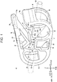
Fig. 1 illustrates a perspective view of a clamp according to a first embodiment (No. 1). -
Fig. 2 illustrates a perspective view of the clamp according to the first embodiment (No. 2). -
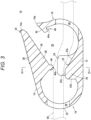
Fig. 3 illustrates a cross-sectional view taken along a central part in a width direction of the clamp ofFig. 1 . -
Fig. 4 illustrates a cross-sectional view taken along the line IV-IV inFig. 3 . -
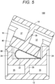
Fig. 5 illustrates a cross-sectional view of an operation example of a clamp according to a comparative example. -
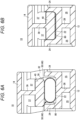
Fig. 6A is a cross-sectional view illustrating an operation for a case where a presser overlies a sidewall in the clamp ofFig. 1 , andFig. 6B is a cross-sectional view illustrating a closed state of a medical tube by the clamp ofFig. 6A . -
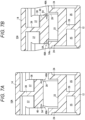
Fig. 7A illustrates a cross-sectional view of a clamp according to a second embodiment, andFig. 7B is a cross-sectional view illustrating an operation for a case where a presser of the clamp ofFig. 7A overlies a sidewall. -
Fig. 8 illustrates a cross-sectional view of a clamp according to a third embodiment. -
Fig. 9 illustrates a cross-sectional view of a clamp according to a fourth embodiment. -
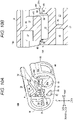
Fig. 10A illustrates a perspective view of a clamp according to a fifth embodiment, andFig. 10B is a cross-sectional view illustrating an operation for a case where a presser of the clamp ofFig. 10A overlies a sidewall. - Hereinafter, preferred embodiments of a clamp of the present invention will be described in detail with reference to the accompanying drawings.
-
Fig. 1 illustrates aclamp 10 according to the present embodiment, and theclamp 10 is integrally formed of a resin material, is attached to amedical tube 80 such as a blood tube or an infusion tube, and is used for an operation of closing and opening themedical tube 80, for example. As illustrated inFig. 1 , theclamp 10 includes a fixedportion 12 on which themedical tube 80 is placed, amovable portion 14 provided above the fixedportion 12 to face the fixedportion 12, acurved portion 16 connecting thefixed portion 12 and themovable portion 14 to each other, anupright portion 18 facing thecurved portion 16, and aclosing portion 20 for closing themedical tube 80. - The
fixed portion 12 is a plate-like portion extending long in the fore-aft direction, and themedical tube 80 is placed on an upper part thereof. Thecurved portion 16 extends upward from a rear end of thefixed portion 12. Theupright portion 18 extends upward from a front end of thefixed portion 12. At a central part of thefixed portion 12 in the fore-aft direction, abase 22 constituting a part of theclosing portion 20 and a pair ofsidewalls 24 extending upward from both sides of thefixed portion 12 in the width direction are formed. - The
curved portion 16 is a member extending upward from thefixed portion 12, and is curved in a semicircular shape when viewed from the side. Thecurved portion 16 can be elastically deformed in a direction of reducing or increasing the radius of curvature. Thecurved portion 16 has, on its central part, afirst insertion hole 28 to penetrate thecurved portion 16 in the thickness direction (fore-aft direction). Thefirst insertion hole 28 is a hole through which to introduce themedical tube 80 into atube arrangement space 30 between thefixed portion 12 and themovable portion 14, and thefirst insertion hole 28 is formed to have dimensions in the width direction and the up-down direction which allow themedical tube 80 to be inserted thereinto. A pair ofcolumn portions 32 is formed on both side portions of thefirst insertion hole 28. The hardness (spring constant) at the time of elastic deformation of thecurved portion 16 is determined depending on thecolumn portions 32. - An upper end of the
curved portion 16 is integrally connected to a rear end of themovable portion 14. Thecurved portion 16 is elastically deformed, so that themovable portion 14 pivots about a rear end of thecurved portion 16, which allows themovable portion 14 to be displaced in the up-down direction of the fixedportion 12. - The
movable portion 14 is a plate-like member, and adistal end 14a thereof is provided above the front end of the fixedportion 12. Aclaw 34 for engaging with alock mechanism 44, described later, is formed on the upper side of thedistal end 14a of themovable portion 14. Theclaw 34 is formed to extend linearly in the width direction. As illustrated inFig. 2 , a plurality ofridges 36 including linear protrusions extending in the width direction is provided on the upper surface of themovable portion 14. Theridges 36 function as non-slip portions when a user applies an operation force to themovable portion 14. - The
movable portion 14 has, on its lower side, aprotrusion 38 and apresser 40 constituting a part of theclosing portion 20. Details of theprotrusion 38 and thepresser 40 are described later with reference to the description of theclosing portion 20. - The
upright portion 18 extends upward from the front end of thefixed portion 12. Theupright portion 18 extends upward while being curved in an arc shape when viewed from the side, and has anupper end portion 18a in which aninclined surface 42 that abuts on a lower portion of thedistal end 14a of themovable portion 14 and thelock mechanism 44 for engaging with theclaw 34. Theinclined surface 42 is formed as a surface that slopes downward toward the rear. In a case where themovable portion 14 is pressed, theinclined surface 42 abuts on thedistal end 14a of themovable portion 14 and slides along the same, and guides thedistal end 14a of themovable portion 14 toward thelock mechanism 44. In response to the pressing force from themovable portion 14 acting on theinclined surface 42, theupright portion 18 is curved so as to be pushed forward to spread out. - The
lock mechanism 44 is a hook-shaped portion having agroove 44a that is formed to be recessed upward and extends in the width direction. In a case where themovable portion 14 is pushed down, thelock mechanism 44 engages with theclaw 34 of thedistal end 14a to prevent themovable portion 14 from returning upward, and locks themovable portion 14 in a state of being pushed downward (pressed state). - The
upright portion 18 has asecond insertion hole 46 below thelock mechanism 44. Thesecond insertion hole 46 is formed to penetrate theupright portion 18 in the thickness direction (fore-aft direction). Thesecond insertion hole 46 is formed in a rectangular shape when viewed from the front. Thesecond insertion hole 46 is formed to have dimensions in the width direction and the up-down direction larger than the diameter of themedical tube 80, which allows themedical tube 80 to be inserted into thesecond insertion hole 46. - As illustrated in
Fig. 1 , themedical tube 80 is introduced into thetube arrangement space 30 between the fixedportion 12 and themovable portion 14 through thefirst insertion hole 28 of thecurved portion 16 and thesecond insertion hole 46 of theupright portion 18. Themedical tube 80 is then closed by the closingportion 20. - Hereinafter, the closing
portion 20 is described. As illustrated inFig. 1 , the closingportion 20 includes thebase 22 and thesidewalls 24 formed on the fixedportion 12 side, and theprotrusion 38 and thepresser 40 formed on themovable portion 14 side. - The
base 22 includes afront surface 22a gently inclined, arear surface 22b extending substantially perpendicular to the fixedportion 12, and anupper end surface 22c that is formed between an upper end of thefront surface 22a and an upper end of therear surface 22b and is parallel to the fixedportion 12, as illustrated inFig. 2 . Theupper end surface 22c is formed at a position where theupper end surface 22c can abut on thepresser 40, described later, in a case where themovable portion 14 is pressed, and theupper end surface 22c functions as a portion that supports themedical tube 80 from below. Each side portion of thebase 22 is hollowed out by ahollow part 25. As illustrated inFig. 4 , thebase 22 is supported from below by arib 26 provided at the center in the width direction. - The pair of
sidewalls 24 is provided on both sides of thebase 22. Thesidewalls 24 are formed to extend in a wall shape above the fixedportion 12 along the side portions of the fixedportion 12. Thesidewalls 24 protrude upward over theupper end surface 22c to prevent themedical tube 80 from being shifted laterally. - On the other hand, the
protrusion 38 is formed to protrude from the lower surface of themovable portion 14 toward the fixedportion 12. Theprotrusion 38 is formed in a triangular shape having a top on the lower end side when viewed from the side. Theprotrusion 38 is formed to have a dimension in the width direction smaller than the distance between the pair ofsidewalls 24, so that theprotrusion 38 can be inserted between the sidewalls 24. Each side portion of theprotrusion 38 is hollowed out by ahollow part 37. Further, as illustrated inFig. 4 , theprotrusion 38 is supported from themovable portion 14 side above by arib 39 provided at the center in the width direction. Thepresser 40 is formed at a lower end of theprotrusion 38. - The
presser 40 is provided above the vicinity of theupper end surface 22c of thebase 22 and is provided to protrude from the lower end of theprotrusion 38. Thepresser 40 is formed in a columnar shape having a central axis in the width direction, and presses and closes themedical tube 80 through alinear contact portion 40a extending in the width direction. Thepresser 40 is formed to have a dimension in the width direction shorter than a gap between the pair of sidewalls 24 (clearance in the width direction) so that thepresser 40 can be inserted between the pair ofsidewalls 24. In addition, on both sides of thepresser 40 in the width direction, a firstinclined structure 48 is formed which is inclined so that the dimension in the width direction of thepresser 40 is decreased toward the lower end. In the present embodiment, the firstinclined structure 48 is configured as aspherical surface 50 as illustrated inFigs. 1 ,2 , and4 . - In addition, as illustrated in
Fig. 4 , a raisedportion 52 curved with the same curvature as the curvature of thespherical surface 50 is formed at a boundary between theupper end surface 22c of thebase 22 and thesidewall 24 in order to fill a gap generated when thepresser 40 is brought into contact with theupper end surface 22c. The raisedportion 52 is formed to extend in the fore-aft direction along bases of thebase 22 and thesidewall 24. The raisedportion 52 is formed over the entire region of thesidewall 24 in the fore-aft direction. The raisedportion 52 is provided to reinforce thesidewall 24. Further, the raisedportion 52 can prevent stress from concentrating on the base of thesidewall 24 when an external force acts on thesidewall 24, which can prevent damage to thesidewall 24. - The
clamp 10 of the present embodiment is configured as described above, and the operation thereof is described below. - As illustrated in
Figs. 1 and3 , theclamp 10 is used by inserting themedical tube 80 into thefirst insertion hole 28 and thesecond insertion hole 46. Themedical tube 80 is placed between the fixedportion 12 and themovable portion 14 as well as between the pair ofsidewalls 24, and is held in thetube arrangement space 30. - When the user presses the
clamp 10 so that thedistal end 14a of themovable portion 14 approaches the fixedportion 12 side, thecurved portion 16 is elastically deformed so as to reduce the radius of curvature. Themovable portion 14 is then displaced so as to approach the fixedportion 12. As illustrated inFig. 6A , themedical tube 80 is pressed while being sandwiched between thepresser 40 and theupper end surface 22c of thebase 22. When themovable portion 14 is further pressed, thedistal end 14a of themovable portion 14 illustrated inFig. 1 slides while being in contact with theinclined surface 42 of theupright portion 18. As themovable portion 14 is pushed down, a load in the direction of tilting theupright portion 18 forward acts through theinclined surface 42, and the upper end of theupright portion 18 is deformed so as to tilt forward. Theclaw 34 of themovable portion 14 is caught by thelock mechanism 44 of theupright portion 18, whereby themovable portion 14 is fixed to thelock mechanism 44. - Since the
clamp 10 has, on thecurved portion 16, thefirst insertion hole 28 into which to insert themedical tube 80, the rigidity of thecurved portion 16 is low. Therefore, when the user performs an operation of pressing themovable portion 14, thedistal end 14a is sometimes shifted in the width direction and thepresser 40 of themovable portion 14 may overlie thesidewall 24. - A
clamp 100 of a comparative example illustrated inFig. 5 illustrates an example in which the firstinclined structure 48 is not provided on both sides of thepresser 40. In theclamp 100 of the comparative example, in a case where thepresser 40 overlies thesidewall 24, that state is maintained. Even in such a case, since themovable portion 14 is formed of a resin material that is elastically deformable, in theclamp 100 of the comparative example, thedistal end 14a of themovable portion 14 is fixed to thelock mechanism 44 with thepresser 40 overlying thesidewall 24. This occurs a situation in which themedical tube 80 is incompletely closed. - In contrast, according to the
clamp 10 of the present embodiment, the firstinclined structure 48 implemented by thespherical surface 50 is formed on both sides of thepresser 40. The firstinclined structure 48 is formed to have a curve inclined so that the dimension in the width direction of thepresser 40 is decreased toward the lower end. Therefore, even when thepresser 40 overlies thesidewall 24 as illustrated inFig. 6A , thepresser 40 is guided between the pair ofsidewalls 24 by the firstinclined structure 48 as indicated by an arrow. As a result, according to theclamp 10 of the present embodiment, as illustrated inFig. 6B , thepresser 40 is reliably inserted between the pair ofsidewalls 24 and the closing operation of themedical tube 80 can be reliably performed. - The
clamp 10 of the present embodiment has the following effects. - The
clamp 10 of the present embodiment includes the fixedportion 12 on which the medical tube 80 (tube) is placed, themovable portion 14 that is provided above the fixedportion 12 to face the fixedportion 12, and the closingportion 20 that presses and closes themedical tube 80 when themovable portion 14 is pressed toward the fixedportion 12. The closingportion 20 includes thepresser 40 that protrudes from themovable portion 14 toward the fixedportion 12 and presses themedical tube 80 with thelinear contact portion 40a extending in the width direction, the pair ofsidewalls 24 that extends, like a wall, from both sides of the fixedportion 12 and prevents themedical tube 80 from being shifted laterally, and the firstinclined structure 48 as a guide structure that is provided in at least one of thepresser 40 and thesidewall 24 and allows thepresser 40 to be guided between the sidewalls 24. - According to the
clamp 10, even in a case where thepresser 40 overlies thesidewall 24, the guide structure guides thepresser 40 toward the inside of thesidewall 24, so that themedical tube 80 can be reliably closed. - In the
clamp 10, the firstinclined structure 48 may be implemented by thespherical surface 50. According to the configuration, thepresser 40 can be guided between the pair ofsidewalls 24 more smoothly. - In the
clamp 10, the raisedportion 52 corresponding to the shape of the firstinclined structure 48 may be formed at the boundary between the fixedportion 12 and thesidewall 24. According to the configuration, since the raisedportion 52 can fill the clearance by the firstinclined structure 48, themedical tube 80 can be reliably closed. - In the
clamp 10, the raisedportion 52 may be formed over the entire region of thesidewall 24 along the extending direction of themedical tube 80. According to the configuration, the rigidity of thesidewall 24 is increased, which can prevent deformation and damage to thesidewall 24. - In the present embodiment described above, the example is described in which the first
inclined structure 48 is implemented by thespherical surface 50; however, the present embodiment is not limited thereto, and the firstinclined structure 48 may be implemented by a flat inclined surface. Alternatively, the firstinclined structure 48 may be implemented by connecting a plurality of inclined surfaces having different inclination angles. -
Fig. 7A illustrates aclamp 10A according to the present embodiment, and theclamp 10A is different from theclamp 10 according to the first embodiment illustrated inFigs. 1 to 4 ,6A, and 6B in configuration of a firstinclined structure 48A of thepresser 40. Note that the configuration of theclamp 10A other than the firstinclined structure 48A is similar to that of theclamp 10 according to the first embodiment. In theclamp 10A, components similar to those of theclamp 10 are denoted by the same reference numerals, and the detailed description thereof is omitted. - As illustrated in
Fig. 7A , theclamp 10A of the present embodiment has the firstinclined structure 48A formed on each side of thepresser 40. The firstinclined structure 48A includes acutout portion 54 formed on each side of thepresser 40. In the illustrated example, thecutout portion 54 is formed in a wedge-like shape; however, the shape is not limited thereto, and various shapes such as a rectangular shape or a semicircular shape can be adopted. The firstinclined structure 48A is not inclined in a state where thepresser 40 does not overlie thesidewall 24. - The
clamp 10A of the present embodiment is configured as described above, and the operation thereof is described below. - As illustrated in
Fig. 7B , when theclamp 10A is pressed in a state where thepresser 40 overlies thesidewall 24, thecutout portion 54 of the firstinclined structure 48A is pushed and flattened. Then, in response to thecutout portion 54 pushed and flattened, aninclined surface 54a is generated on the side portion of thepresser 40. Theinclined surface 54a is inclined in such a direction that the dimension in the width direction of thepresser 40 is decreased toward the lower end, and when themovable portion 14 is pressed toward the fixedportion 12, thepresser 40 is guided between the pair ofsidewalls 24 by theinclined surface 54a. In this manner, the firstinclined structure 48A also functions as a structure that allows thepresser 40 to be guided between the pair ofsidewalls 24. - The
clamp 10A of the present embodiment has the following effects. - The
clamp 10A has, as the guide structure, the firstinclined structure 48A that is formed in thepresser 40 and generates, in thepresser 40, an inclined surface that is inclined toward the inside of thesidewall 24 when thepresser 40 abuts on the upper end of thesidewall 24. - The
clamp 10A also achieves the effect similar to that of theclamp 10 according to the first embodiment. - Note that, in the
clamp 10A of the present embodiment, the firstinclined structure 48A is not limited to thecutout portion 54, and may be implemented by a member that generates an inclined surface as elastic compression proceeds more than other portions by applying a load that presses thepresser 40 against thesidewall 24. For example, the firstinclined structure 48A may be implemented by arranging an elastically compressible material on both sides of thepresser 40. -
Fig. 8 illustrates aclamp 10B of the present embodiment, and theclamp 10B includes a secondinclined structure 56 at the upper end of asidewall 24A as a guide structure that allows thepresser 40 to be guided between the sidewalls 24A. In theclamp 10B of the present embodiment, components similar to those of theclamp 10 according to the first embodiment are denoted by the same reference numerals, and the detailed description thereof is omitted. - In the
clamp 10B, the secondinclined structure 56 is provided at the upper end of thesidewall 24A instead of providing the inclined structure on each side of thepresser 40. The secondinclined structure 56 is inclined toward the inside of the pair ofsidewalls 24A. To be specific, the secondinclined structure 56 of thesidewall 24A on the left side inFig. 8 is inclined downward from the side edge of the left end toward the inside (right side), and is an inclined surface that guides the side portion of thepresser 40 toward the inside of thesidewall 24A. In addition, the secondinclined structure 56 of thesidewall 24A on the right side is inclined downward from the side edge of the right end toward the inside (left side), and is an inclined surface that guides thepresser 40 abutting on thesidewall 24A on the right side toward the inside of thesidewall 24A. - The
clamp 10B of the present embodiment has the following effects. - The
clamp 10B of the present embodiment has, as the guide structure, the secondinclined structure 56 that is formed on the upper end of thesidewall 24A and is inclined toward the inside of thesidewall 24A. - According to the
clamp 10B, even in a case where thepresser 40 overlies thesidewall 24A, the secondinclined structure 56 guides thepresser 40 toward the inside of thesidewall 24A, so that themedical tube 80 can be reliably closed. - In the
clamp 10B of the present embodiment, the secondinclined structure 56 is not limited to the flat surface, and may be implemented by a curve such as a spherical surface or a paraboloid surface. In addition, the firstinclined structure 48 may be formed on thepresser 40 side. -
Fig. 9 illustrates aclamp 10C of the present embodiment, and theclamp 10C includes a secondinclined structure 56A at the upper end of thesidewall 24 as the guide structure that allows thepresser 40 to be guided between the sidewalls 24. In theclamp 10C of the present embodiment, components similar to those of theclamp 10 according to the first embodiment are denoted by the same reference numerals, and the detailed description thereof is omitted. - The second
inclined structure 56A of the present embodiment has acutout portion 58 formed in an inner portion of thesidewall 24. However, the upper end of thesidewall 24 is configured by a flat surface substantially parallel to the bottom surface of the fixedportion 12 while not abutting on thepresser 40. In the illustrated example, the firstinclined structure 48 is formed on both sides of thepresser 40; however, the present embodiment is not limited thereto and it is possible that the firstinclined structure 48 is not formed. - The
clamp 10C of the present embodiment is configured as described above, and the operation thereof is described below. - When the
movable portion 14 of theclamp 10C is pressed and thepresser 40 abuts on the upper end of thesidewall 24, thecutout portion 58 of the secondinclined structure 56A is pushed and flattened due to a load applied from the upper end of thesidewall 24. As a result, the upper end of thesidewall 24 becomes an inclined surface inclined inward. The inclined surface allows thepresser 40 to be guided between the sidewalls 24. As described above, the secondinclined structure 56A has a structure in which the inclined surface appears in response to thepresser 40 abutting. - The
clamp 10C of the present embodiment has the following effects. - The
clamp 10C has, as the guide structure, the secondinclined structure 56A that is formed in thesidewall 24 and generates an inclined surface inclined inward in the upper end of thesidewall 24 in response to thepresser 40 abutting. - According to the
clamp 10C, even in a case where thepresser 40 overlies thesidewall 24, the secondinclined structure 56A guides thepresser 40 toward the inside of thesidewall 24, so that themedical tube 80 can be reliably closed. -
Fig. 10A illustrates aclamp 10D, and theclamp 10D has a secondinclined structure 56B on thesidewall 24A as a guide structure that allows thepresser 40 to be guided between the sidewalls 24A. In theclamp 10D of the present embodiment, components similar to those of theclamp 10 according to the first embodiment are denoted by the same reference numerals, and the detailed description thereof is omitted. - The
sidewall 24A of the present embodiment is formed in a frame shape. The upper end of thesidewall 24A is configured by aplate member 60. The front end and the rear end of theplate member 60 are supported bysupport portions hole 62 is provided below theplate member 60. - The second
inclined structure 56B includes a plurality ofcutout grooves 64 formed inside theplate member 60. Thecutout grooves 64 are formed to a predetermined depth from the upper side toward the lower side of theplate member 60. Incidentally, thecutout grooves 64 may be formed to penetrate theplate member 60 in the up-down direction. Alternatively, thecutout grooves 64 may be formed so as to be cut from the lower side of theplate member 60 toward the upward direction. - The
clamp 10D of the present embodiment is configured as described above, and the operation thereof is described below. - As illustrated in
Fig. 10B , when thepresser 40 overlies the upper end of thesidewall 24A, theplate member 60 is deformed about thecutout groove 64 due to a load applied from thepresser 40. Since thecutout groove 64 is formed inside, theplate member 60 is deformed so as to be inclined inward as illustrated inFig. 10B . Then, an inclined surface inclined inward is generated on the upper surface of theplate member 60. In this manner, the secondinclined structure 56B forms an inclined surface that guides thepresser 40 inward when thepresser 40 overlies thesidewall 24A. As a result, in theclamp 10D, thepresser 40 is guided between the sidewalls 24A, so that themedical tube 80 can be reliably closed. - Although the present invention has been described above with reference to preferred embodiments, the present invention is not limited to the above embodiments, and it goes without saying that various modifications can be made without departing from the gist of the present invention.
Claims (8)
- A clamp comprising:a fixed portion on which a tube is placed;a movable portion that is provided above the fixed portion to face the fixed portion; anda closing portion configured to press and close the tube in response to the movable portion pressed toward the fixed portion, whereinthe closing portion includesa presser that protrudes from the movable portion toward the fixed portion and presses the tube,a pair of sidewalls that extends in a wall shape from both sides of the fixed portion and prevents the tube from being shifted laterally, anda guide structure that is provided in at least one of the presser and the sidewalls and allows the presser to be guided between the sidewalls.
- The clamp according to claim 1, wherein the guide structure includes a first inclined structure that is formed in a side of the presser and is inclined toward inside of the sidewall.
- The clamp according to claim 2, wherein the first inclined structure has a spherical surface.
- The clamp according to claim 3, wherein a raised portion corresponding to a shape of the first inclined structure is formed at a boundary between the fixed portion and the sidewall.
- The clamp according to claim 4, wherein the raised portion is formed over an entire region of the sidewall along an extending direction of the tube.
- The clamp according to claim 1, wherein the guide structure includes a first inclined structure that is formed in the presser and forms, in the presser, an inclined surface toward inside of the sidewall in response to the presser abutting on an upper end of the sidewall.
- The clamp according to claim 1, wherein the guide structure includes a second inclined structure that is formed in an upper end surface of the sidewall and is inclined toward inside of the sidewall.
- The clamp according to claim 1, wherein the guide structure includes a second inclined structure that is formed in the sidewall and forms, in an upper end of the sidewall, an inclined surface inclined inward in response to the presser abutting.
Applications Claiming Priority (2)
| Application Number | Priority Date | Filing Date | Title |
|---|---|---|---|
| JP2020083048 | 2020-05-11 | ||
| PCT/JP2021/017190 WO2021230105A1 (en) | 2020-05-11 | 2021-04-30 | Clamp |
Publications (2)
| Publication Number | Publication Date |
|---|---|
| EP4129394A1 true EP4129394A1 (en) | 2023-02-08 |
| EP4129394A4 EP4129394A4 (en) | 2023-09-06 |
Family
ID=78525756
Family Applications (1)
| Application Number | Title | Priority Date | Filing Date |
|---|---|---|---|
| EP21803956.8A Pending EP4129394A4 (en) | 2020-05-11 | 2021-04-30 | Clamp |
Country Status (5)
| Country | Link |
|---|---|
| US (1) | US12013056B2 (en) |
| EP (1) | EP4129394A4 (en) |
| JP (2) | JP7620625B2 (en) |
| CN (1) | CN115485012B (en) |
| WO (1) | WO2021230105A1 (en) |
Families Citing this family (1)
| Publication number | Priority date | Publication date | Assignee | Title |
|---|---|---|---|---|
| CN119565011A (en) * | 2024-12-31 | 2025-03-07 | 振德医疗用品股份有限公司 | Applicator, smearing device and smearing set |
Family Cites Families (14)
| Publication number | Priority date | Publication date | Assignee | Title |
|---|---|---|---|---|
| DE3039591A1 (en) * | 1980-10-21 | 1982-05-19 | Günter van Dr.med. 4000 Düsseldorf Endert | ADAPTER |
| US4346869A (en) * | 1981-03-12 | 1982-08-31 | Macneill Robert L | Tube clamp |
| DE9310226U1 (en) * | 1993-07-09 | 1993-09-30 | Spang & Brands GmbH, 61381 Friedrichsdorf | Hose clamp |
| IL127029A (en) * | 1998-11-12 | 2002-03-10 | Medivice Systems Ltd | Pinch clamp |
| US20120035553A1 (en) * | 2009-03-23 | 2012-02-09 | Gambro Lundia Ab | Clamp for closing flexible tubing belonging to medical equipment |
| EP2676690B1 (en) * | 2011-02-17 | 2021-07-28 | Nipro Corporation | Medical tube clamp |
| CN106659829B (en) * | 2014-06-30 | 2020-03-03 | 日机装株式会社 | Clamping device for flexible pipe |
| JP6082433B2 (en) * | 2015-06-22 | 2017-02-15 | 日機装株式会社 | Clamping device |
| US11040186B2 (en) * | 2015-10-28 | 2021-06-22 | Becton, Dickinson And Company | Pinch clamp device |
| US10907739B2 (en) * | 2016-03-03 | 2021-02-02 | Christine L. Jeep Trustee of the Louis & Patricia Mueller Family Trust, Dated April 2nd, 2020 | Pinch valve |
| JP2018000836A (en) | 2016-07-08 | 2018-01-11 | 川澄化学工業株式会社 | Clamp and medical instrument |
| DE102017212883A1 (en) * | 2017-07-26 | 2019-01-31 | B. Braun Melsungen Ag | Hose clamp for clamping a medical hose |
| US10932789B2 (en) * | 2018-04-11 | 2021-03-02 | Covidien Lp | Ligation clip with latching and retention features |
| FR3093928B1 (en) * | 2019-03-19 | 2021-02-19 | Maco Pharma Sa | Clamp for reshaping a flexible tube forming part of a medical device |
-
2021
- 2021-04-30 JP JP2022521841A patent/JP7620625B2/en active Active
- 2021-04-30 CN CN202180032571.1A patent/CN115485012B/en active Active
- 2021-04-30 WO PCT/JP2021/017190 patent/WO2021230105A1/en not_active Ceased
- 2021-04-30 EP EP21803956.8A patent/EP4129394A4/en active Pending
-
2022
- 2022-10-20 US US17/970,324 patent/US12013056B2/en active Active
-
2024
- 2024-08-21 JP JP2024139376A patent/JP7635455B2/en active Active
Also Published As
| Publication number | Publication date |
|---|---|
| JP7620625B2 (en) | 2025-01-23 |
| JP2024152886A (en) | 2024-10-25 |
| CN115485012A (en) | 2022-12-16 |
| US20230037423A1 (en) | 2023-02-09 |
| WO2021230105A1 (en) | 2021-11-18 |
| EP4129394A4 (en) | 2023-09-06 |
| JPWO2021230105A1 (en) | 2021-11-18 |
| US12013056B2 (en) | 2024-06-18 |
| JP7635455B2 (en) | 2025-02-25 |
| CN115485012B (en) | 2026-03-31 |
Similar Documents
| Publication | Publication Date | Title |
|---|---|---|
| US5554052A (en) | Locking connector | |
| US11292396B2 (en) | Bracket for vehicle mount device | |
| US20020115340A1 (en) | Electrical connector | |
| US9509077B2 (en) | Connector with locking lance and terminal fitting with deflection regulating portion for regulating deflection of the locking lance | |
| US20180364076A1 (en) | Sensor bracket | |
| US6655993B1 (en) | Terminal-retainment cancellation structure of connector | |
| CN107017522B (en) | Connector | |
| JPH1050429A (en) | Electrical connector for circuit board insertion | |
| EP4068523B1 (en) | Connector | |
| JP7635455B2 (en) | Clamp | |
| JP4331703B2 (en) | Card connector with eject mechanism using heart cam | |
| JP7424247B2 (en) | connector | |
| JP7569851B2 (en) | Clamp | |
| JP6852448B2 (en) | Clip mounting seat | |
| US20240339777A1 (en) | Connector | |
| KR20190105500A (en) | Connector | |
| US7070451B2 (en) | Card connector | |
| US20020001985A1 (en) | Connector | |
| JP2007012551A (en) | Card connector | |
| US6065983A (en) | Connector | |
| JP2021177803A (en) | Clamp | |
| US10886662B2 (en) | Electrical card connector | |
| JP2007048606A (en) | Card connector | |
| JP4021257B2 (en) | Switch device | |
| JP7286514B2 (en) | connector |
Legal Events
| Date | Code | Title | Description |
|---|---|---|---|
| STAA | Information on the status of an ep patent application or granted ep patent |
Free format text: STATUS: THE INTERNATIONAL PUBLICATION HAS BEEN MADE |
|
| PUAI | Public reference made under article 153(3) epc to a published international application that has entered the european phase |
Free format text: ORIGINAL CODE: 0009012 |
|
| STAA | Information on the status of an ep patent application or granted ep patent |
Free format text: STATUS: REQUEST FOR EXAMINATION WAS MADE |
|
| 17P | Request for examination filed |
Effective date: 20221031 |
|
| AK | Designated contracting states |
Kind code of ref document: A1 Designated state(s): AL AT BE BG CH CY CZ DE DK EE ES FI FR GB GR HR HU IE IS IT LI LT LU LV MC MK MT NL NO PL PT RO RS SE SI SK SM TR |
|
| DAV | Request for validation of the european patent (deleted) | ||
| DAX | Request for extension of the european patent (deleted) | ||
| A4 | Supplementary search report drawn up and despatched |
Effective date: 20230804 |
|
| RIC1 | Information provided on ipc code assigned before grant |
Ipc: A61M 39/28 20060101AFI20230731BHEP |