EP4129141A1 - Installation support and autonomous mobile robot - Google Patents
Installation support and autonomous mobile robot Download PDFInfo
- Publication number
- EP4129141A1 EP4129141A1 EP21826985.0A EP21826985A EP4129141A1 EP 4129141 A1 EP4129141 A1 EP 4129141A1 EP 21826985 A EP21826985 A EP 21826985A EP 4129141 A1 EP4129141 A1 EP 4129141A1
- Authority
- EP
- European Patent Office
- Prior art keywords
- magnetic element
- rotating shaft
- mounting bracket
- housing
- bracket according
- Prior art date
- Legal status (The legal status is an assumption and is not a legal conclusion. Google has not performed a legal analysis and makes no representation as to the accuracy of the status listed.)
- Pending
Links
Images
Classifications
-
- A—HUMAN NECESSITIES
- A47—FURNITURE; DOMESTIC ARTICLES OR APPLIANCES; COFFEE MILLS; SPICE MILLS; SUCTION CLEANERS IN GENERAL
- A47L—DOMESTIC WASHING OR CLEANING; SUCTION CLEANERS IN GENERAL
- A47L11/00—Machines for cleaning floors, carpets, furniture, walls, or wall coverings
-
- A—HUMAN NECESSITIES
- A47—FURNITURE; DOMESTIC ARTICLES OR APPLIANCES; COFFEE MILLS; SPICE MILLS; SUCTION CLEANERS IN GENERAL
- A47L—DOMESTIC WASHING OR CLEANING; SUCTION CLEANERS IN GENERAL
- A47L11/00—Machines for cleaning floors, carpets, furniture, walls, or wall coverings
- A47L11/40—Parts or details of machines not provided for in groups A47L11/02 - A47L11/38, or not restricted to one of these groups, e.g. handles, arrangements of switches, skirts, buffers, levers
- A47L11/4002—Installations of electric equipment
-
- B—PERFORMING OPERATIONS; TRANSPORTING
- B25—HAND TOOLS; PORTABLE POWER-DRIVEN TOOLS; MANIPULATORS
- B25J—MANIPULATORS; CHAMBERS PROVIDED WITH MANIPULATION DEVICES
- B25J9/00—Program-controlled manipulators
- B25J9/0009—Constructional details, e.g. manipulator supports, bases
-
- A—HUMAN NECESSITIES
- A47—FURNITURE; DOMESTIC ARTICLES OR APPLIANCES; COFFEE MILLS; SPICE MILLS; SUCTION CLEANERS IN GENERAL
- A47L—DOMESTIC WASHING OR CLEANING; SUCTION CLEANERS IN GENERAL
- A47L11/00—Machines for cleaning floors, carpets, furniture, walls, or wall coverings
- A47L11/40—Parts or details of machines not provided for in groups A47L11/02 - A47L11/38, or not restricted to one of these groups, e.g. handles, arrangements of switches, skirts, buffers, levers
- A47L11/4011—Regulation of the cleaning machine by electric means; Control systems and remote control systems therefor
-
- A—HUMAN NECESSITIES
- A47—FURNITURE; DOMESTIC ARTICLES OR APPLIANCES; COFFEE MILLS; SPICE MILLS; SUCTION CLEANERS IN GENERAL
- A47L—DOMESTIC WASHING OR CLEANING; SUCTION CLEANERS IN GENERAL
- A47L11/00—Machines for cleaning floors, carpets, furniture, walls, or wall coverings
- A47L11/40—Parts or details of machines not provided for in groups A47L11/02 - A47L11/38, or not restricted to one of these groups, e.g. handles, arrangements of switches, skirts, buffers, levers
- A47L11/4061—Steering means; Means for avoiding obstacles; Details related to the place where the driver is accommodated
-
- B—PERFORMING OPERATIONS; TRANSPORTING
- B25—HAND TOOLS; PORTABLE POWER-DRIVEN TOOLS; MANIPULATORS
- B25J—MANIPULATORS; CHAMBERS PROVIDED WITH MANIPULATION DEVICES
- B25J11/00—Manipulators not otherwise provided for
- B25J11/008—Manipulators for service tasks
- B25J11/0085—Cleaning
-
- B—PERFORMING OPERATIONS; TRANSPORTING
- B25—HAND TOOLS; PORTABLE POWER-DRIVEN TOOLS; MANIPULATORS
- B25J—MANIPULATORS; CHAMBERS PROVIDED WITH MANIPULATION DEVICES
- B25J19/00—Accessories fitted to manipulators, e.g. for monitoring, for viewing; Safety devices combined with or specially adapted for use in connection with manipulators
- B25J19/02—Sensing devices
- B25J19/021—Optical sensing devices
- B25J19/022—Optical sensing devices using lasers
-
- F—MECHANICAL ENGINEERING; LIGHTING; HEATING; WEAPONS; BLASTING
- F16—ENGINEERING ELEMENTS AND UNITS; GENERAL MEASURES FOR PRODUCING AND MAINTAINING EFFECTIVE FUNCTIONING OF MACHINES OR INSTALLATIONS; THERMAL INSULATION IN GENERAL
- F16B—DEVICES FOR FASTENING OR SECURING CONSTRUCTIONAL ELEMENTS OR MACHINE PARTS TOGETHER, e.g. NAILS, BOLTS, CIRCLIPS, CLAMPS, CLIPS OR WEDGES; JOINTS OR JOINTING
- F16B1/00—Devices for securing together, or preventing relative movement between, constructional elements or machine parts
-
- G—PHYSICS
- G01—MEASURING; TESTING
- G01B—MEASURING LENGTH, THICKNESS OR SIMILAR LINEAR DIMENSIONS; MEASURING ANGLES; MEASURING AREAS; MEASURING IRREGULARITIES OF SURFACES OR CONTOURS
- G01B11/00—Measuring arrangements characterised by the use of optical techniques
- G01B11/02—Measuring arrangements characterised by the use of optical techniques for measuring length, width or thickness
- G01B11/026—Measuring arrangements characterised by the use of optical techniques for measuring length, width or thickness by measuring distance between sensor and object
-
- G—PHYSICS
- G01—MEASURING; TESTING
- G01B—MEASURING LENGTH, THICKNESS OR SIMILAR LINEAR DIMENSIONS; MEASURING ANGLES; MEASURING AREAS; MEASURING IRREGULARITIES OF SURFACES OR CONTOURS
- G01B5/00—Measuring arrangements characterised by the use of mechanical techniques
- G01B5/0002—Arrangements for supporting, fixing or guiding the measuring instrument or the object to be measured
- G01B5/0004—Supports
-
- G—PHYSICS
- G01—MEASURING; TESTING
- G01S—RADIO DIRECTION-FINDING; RADIO NAVIGATION; DETERMINING DISTANCE OR VELOCITY BY USE OF RADIO WAVES; LOCATING OR PRESENCE-DETECTING BY USE OF THE REFLECTION OR RERADIATION OF RADIO WAVES; ANALOGOUS ARRANGEMENTS USING OTHER WAVES
- G01S17/00—Systems using the reflection or reradiation of electromagnetic waves other than radio waves, e.g. lidar systems
- G01S17/02—Systems using the reflection of electromagnetic waves other than radio waves
- G01S17/06—Systems determining position data of a target
- G01S17/42—Simultaneous measurement of distance and other co-ordinates
-
- G—PHYSICS
- G01—MEASURING; TESTING
- G01S—RADIO DIRECTION-FINDING; RADIO NAVIGATION; DETERMINING DISTANCE OR VELOCITY BY USE OF RADIO WAVES; LOCATING OR PRESENCE-DETECTING BY USE OF THE REFLECTION OR RERADIATION OF RADIO WAVES; ANALOGOUS ARRANGEMENTS USING OTHER WAVES
- G01S17/00—Systems using the reflection or reradiation of electromagnetic waves other than radio waves, e.g. lidar systems
- G01S17/88—Lidar systems specially adapted for specific applications
- G01S17/93—Lidar systems specially adapted for specific applications for anti-collision purposes
- G01S17/931—Lidar systems specially adapted for specific applications for anti-collision purposes of land vehicles
-
- G—PHYSICS
- G01—MEASURING; TESTING
- G01S—RADIO DIRECTION-FINDING; RADIO NAVIGATION; DETERMINING DISTANCE OR VELOCITY BY USE OF RADIO WAVES; LOCATING OR PRESENCE-DETECTING BY USE OF THE REFLECTION OR RERADIATION OF RADIO WAVES; ANALOGOUS ARRANGEMENTS USING OTHER WAVES
- G01S7/00—Details of systems according to groups G01S13/00, G01S15/00, G01S17/00
- G01S7/48—Details of systems according to groups G01S13/00, G01S15/00, G01S17/00 of systems according to group G01S17/00
- G01S7/481—Constructional features, e.g. arrangements of optical elements
- G01S7/4811—Constructional features, e.g. arrangements of optical elements common to transmitter and receiver
- G01S7/4813—Housing arrangements
-
- G—PHYSICS
- G01—MEASURING; TESTING
- G01S—RADIO DIRECTION-FINDING; RADIO NAVIGATION; DETERMINING DISTANCE OR VELOCITY BY USE OF RADIO WAVES; LOCATING OR PRESENCE-DETECTING BY USE OF THE REFLECTION OR RERADIATION OF RADIO WAVES; ANALOGOUS ARRANGEMENTS USING OTHER WAVES
- G01S7/00—Details of systems according to groups G01S13/00, G01S15/00, G01S17/00
- G01S7/48—Details of systems according to groups G01S13/00, G01S15/00, G01S17/00 of systems according to group G01S17/00
- G01S7/497—Means for monitoring or calibrating
- G01S7/4972—Alignment of sensor
-
- A—HUMAN NECESSITIES
- A47—FURNITURE; DOMESTIC ARTICLES OR APPLIANCES; COFFEE MILLS; SPICE MILLS; SUCTION CLEANERS IN GENERAL
- A47L—DOMESTIC WASHING OR CLEANING; SUCTION CLEANERS IN GENERAL
- A47L2201/00—Robotic cleaning machines, i.e. with automatic control of the travelling movement or the cleaning operation
-
- F—MECHANICAL ENGINEERING; LIGHTING; HEATING; WEAPONS; BLASTING
- F16—ENGINEERING ELEMENTS AND UNITS; GENERAL MEASURES FOR PRODUCING AND MAINTAINING EFFECTIVE FUNCTIONING OF MACHINES OR INSTALLATIONS; THERMAL INSULATION IN GENERAL
- F16B—DEVICES FOR FASTENING OR SECURING CONSTRUCTIONAL ELEMENTS OR MACHINE PARTS TOGETHER, e.g. NAILS, BOLTS, CIRCLIPS, CLAMPS, CLIPS OR WEDGES; JOINTS OR JOINTING
- F16B2200/00—Constructional details of connections not covered for in other groups of this subclass
- F16B2200/83—Use of a magnetic material
Definitions
- the present disclosure relates to the field of robot technologies, and in particular, to a mounting bracket and a self-propelled robot.
- a robot is usually equipped with a laser distance sensor (LDS), which is configured to measure distances between the robot and various obstacles in an area in which the robot is located, so that the robot creates a map of the area, avoids the obstacles and locates itself in the area.
- LDS laser distance sensor
- LDSs are rotatably mounted on robots, and distances between the robots and nearby obstacles can be measured by rotating the LDSs.
- a technical problem to be solved in the present disclosure is how to provide a mounting bracket which can alleviate an offset and jitter during rotation of a laser distance sensor.
- Another technical problem to be solved in the present disclosure is how to provide a self-propelled robot having the mounting bracket.
- An embodiment of the present disclosure provides a mounting bracket, configured to rotatably mount a laser distance sensor on a base body.
- the mounting bracket includes a housing, a rotating shaft and a magnetic positioning assembly.
- the housing is provided with an inner cavity.
- the rotating shaft is vertically and rotatably arranged in the inner cavity.
- the magnetic positioning assembly includes a first magnetic element and a second magnetic element which are respectively arranged on the housing and the rotating shaft.
- the laser distance sensor is arranged on the rotating shaft; and in a case that the rotating shaft deviates from an axis, the mounting bracket is configured to generate a force between the first magnetic element and the second magnetic element in a radial direction of the rotating shaft so that the rotating shaft is positioned with respect to the housing.
- the first magnetic element is arranged at a position, corresponding to an upper end of the rotating shaft, of the housing, and the second magnetic element is arranged at the upper end of the rotating shaft.
- the first magnetic element is symmetrically arranged relative to the axis of the rotating shaft and the second magnetic element is symmetrically arranged relative to the axis of the rotating shaft.
- a polarity of the first magnetic element and a polarity of the second magnetic element are identical.
- the first magnetic element has an annular structure, an inner diameter of the first magnetic element is greater than an outer diameter of the second magnetic element, and the first magnetic element is sleeved on the second magnetic element.
- an inner surface of a top of the housing is provided with a first bump that bumps downwards, and the first magnetic element is attached to the first bump.
- the second magnetic element has an annular structure, and an axis of the annular structure coincides with the axis of the rotating shaft.
- the upper end of the rotating shaft is provided with a second bump that bumps upwards, and the second magnetic element is arranged around the second bump.
- a polarity of the first magnetic element and a polarity of the second magnetic element are opposite.
- the first magnetic element has a plate-shaped structure.
- the second magnetic element has a plate-shaped structure.
- the upper end of the rotating shaft horizontally extends to form a platform, and the second magnetic element is arranged on the platform; and/or a groove is provided at a position, corresponding to the rotating shaft, of an outer surface of a top of the housing, and the first magnetic element is arranged in the groove.
- An embodiment of the present disclosure provides a self-propelled robot, including a base body and a laser distance sensor.
- the self-propelled robot further includes the mounting bracket described in the foregoing embodiments of the present disclosure, which is mounted on the base body through the housing.
- the laser distance sensor is arranged on the rotating shaft of the mounting bracket.
- the laser distance sensor is arranged on the rotating shaft of the mounting bracket disclosed in the embodiments of the present disclosure, and the rotating shaft deviates from the axis in a rotation process, the mounting bracket can position the rotating shaft with respect to the housing through the force in the radial direction of the rotating shaft, so that an offset and jitter generated during rotation of the laser distance sensor can be effectively alleviated, thereby improving reliability and precision of the products, prolonging service lives of the products, and the like.
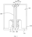
- FIG. 1 schematically illustrates a cross-sectional view of a mounting bracket provided in an embodiment of the present disclosure according to an exemplary embodiment.
- the mounting bracket according to the present disclosure is illustrated through an example in which the mounting bracket is applied to a robot such as a sweeping robot.
- a robot such as a sweeping robot.
- the mounting bracket according to the present disclosure can be configured to rotatably mount a laser distance sensor on a base body (for example, a housing of a sweeping robot).
- the mounting bracket includes a housing, a rotating shaft 200 and a magnetic positioning assembly. The structure, the connecting way and the functional relationship of main components of the mounting bracket according to the embodiment of the present disclosure are described in detail with reference to FIG. 1 .
- the housing is provided with an inner cavity 130.
- the inner cavity 130 may be a closed space formed by the housing which can be made of a material capable of emitting light through the laser distance sensor.
- the rotating shaft 200 is vertically arranged and is rotatably arranged in the inner cavity 130.
- the magnetic positioning assembly includes two magnetic elements which are respectively attached to the housing and the rotating shaft 200.
- the magnetic element arranged on the rotating shaft 200 is referred to as the second magnetic element 410 and the magnetic element arranged on the housing is referred to as the first magnetic element 420.
- the mounting bracket according to the present disclosure may position the rotating shaft 200 with respect to the housing through a magnetic force between the two magnetic elements.
- the technical solution according to the embodiment of the present disclosure can position the positioning shaft 200 with respect to the housing through a force in a radial direction of the rotating shaft 200 between the first magnetic element 420 and the second magnetic element 410.
- the mounting bracket according to the embodiment of the present disclosure can effectively alleviate an offset and jitter generated during rotation of the laser distance sensor, thereby improving reliability and precision of the products, prolonging service lives of the products, and the like.
- the principle of attraction of opposite magnetisms and repellence of identical magnetisms between the second magnetic element and the first magnetic element can be utilized to generate a force in the radial direction of the rotating shaft 200 to position the rotating shaft 200; and moreover, the rotating shaft 200 is not in direct contact with a structure such as a case (for example, a second case 120), further reducing friction between components.
- the housing can include a first case 110 and the second case 120.
- the second case 120 is detachably arranged on the first case 110, and the first case 110 and the second case 120 cooperatively form a housing and defines the inner cavity 130 of the housing.
- a lower end of the rotating shaft 200 is rotatably arranged on the first case 110.
- the housing can alternatively have another structure, such as an integrated structure.
- the two housings are not limited to the vertical combination way in the embodiment, for example, can be juxtaposed.
- an upper end of the rotating shaft may be rotatably engaged with the housing. This is not limited in the embodiment.
- an inner surface of a bottom of the first case 110 can be equipped with a shaft seat 111.
- the lower end of the rotating shaft 200 can be rotatably arranged on the shaft seat 111 through a bearing.
- a plurality of bearings can be arranged between the rotating shaft 200 and the shaft seat 111, and the embodiment is described through an example in which there are two bearings.
- the two bearings are respectively defined as a first bearing 310 and a second bearing 320 in the specification.
- the two bearings are arranged between the rotating shaft 200 and the shaft seat 111 at intervals in a vertical direction (namely, an axial direction of the rotating shaft 200), and the second bearing 320 is located above the first bearing 310.
- a shaft cavity which extends along the axis is defined inside the rotating shaft 200.
- the first magnetic element 420 can be symmetrically arranged relative to the axis.
- a center of a circle corresponding to the first magnetic element 420 is positioned on the rotating shaft 200 or an extending line thereof.
- a geometric center thereof is positioned on the rotating shaft 200 or the extending line thereof. That is, the first magnetic element 420 has a ring-shaped or plate-shaped structure in central symmetry, wherein the central symmetry indicates a symmetrical shape with respect to its geometric center positioned on the rotating shaft 200 or the extending line thereof.
- the second magnetic element 410 may be symmetrically arranged with respect to the axis.
- a circle center of a circle corresponding to the second magnetic element is positioned on the rotating shaft 200 or an extending line thereof.
- a geometric center thereof is positioned on the rotating shaft 200 or the extending line thereof. That is, the second magnetic element 410 has a ring-shaped or plate-shaped structure in central symmetry, wherein the central symmetry indicates a symmetrical shape with respect to its geometric center positioned on the rotating shaft 200 or the extending line thereof.
- the magnetic positioning assembly is arranged between the housing and the upper end of the rotating shaft 200.
- the second magnetic element 410 is arranged at the upper end of the rotating shaft 200
- the first magnetic element 420 is arranged on a position, corresponding to the upper end of the rotating shaft 200, of the housing.
- the second magnetic element 410 and the first magnetic element 420 have annular structures respectively, axes of which coincide with the axis.
- a polarity of the second magnetic element 410 and a polarity of the first magnetic element 420 are identical, so that magnetic repulsive force is generated between the second magnetic element 410 and the first magnetic element 420.
- an outer diameter of the second magnetic element 410 may be less than an inner diameter of the first magnetic element 420, so that the first magnetic element 420 may be arranged around the second magnetic element 410; and a clearance is formed between the inner ring surface of the first magnetic element 420 and the outer ring surface of the second magnetic element 410. Therefore, in a case that the rotating shaft 200 deviates from the axis, the magnetic repulsive force includes force which is applied to the second magnetic element 410 (indirectly applied to the rotating shaft 200) in the radial direction of the rotating shaft 200 along the axis thereof, thereby positioning the rotating shaft 200 on the axis.
- the second magnetic element 410 may have a circular-ring-shaped structure.
- the second magnetic element may have a polygonal annular structure or the like. This is not limited in the embodiment.
- the first magnetic element 420 may have a circular-ring-shaped structure.
- the first magnetic element may have a polygonal annular structure or the like. This is not limited in the embodiment.
- the upper end of the rotating shaft 200 may be provided with a second bump 210 that bumps upwards, and accordingly, the second magnetic element 410 is arranged around the second bump 210.
- the second bump 210 may be cylindrical, and the second magnetic element 410 is arranged around an outer ring surface of the second bump 210.
- a diameter of a circle corresponding to a cross section of the second bump 210 may be equal to or slightly greater than an inner diameter of the second magnetic element 410, so that the second magnetic element 410 is arranged around the second bump 210 in a tight fit or interference fit mode, and the second magnetic element 410 is further prevented from radial wobble and axial jolt in a high-speed rotation of the rotating shaft 200.
- the second bump in a case that the second magnetic element has a polygonal annular structure, the second bump may also have a corresponding polyprism-shaped structure.
- the lower surface of the top of the housing (for example, the second case 120) can be provided with a first bump 121 that bumps downwards (that is, facing the rotating shaft 200), and accordingly, the first magnetic element 420 is arranged around the first bump 121.
- the first bump 121 may have a shape of a circular ring, and the first magnetic element 420 is arranged around the inner ring surface of the first bump 121.
- a diameter of a circle corresponding to the cross section of the first bump 121 may be equal to or slightly less than an inner diameter of the first magnetic element 420, so that the first magnetic element 420 is arranged around the second first structure 121 in a tight fit or interference fit, and the combination degree between the first magnetic element 420 and the housing is further improved.
- the second bump in a case that the first magnetic element has a polygonal annular structure, the second bump may also have a corresponding polygonal ring-shaped structure.
- the second bump may also have a shape of a circular ring, and the outer ring of the second magnetic element is sleeved by the inner ring surface of the second bump.
- the first bump is cylindrical, and the inner ring of the first magnetic element is arranged around the outer ring surface of the first bump. This is not limited in the embodiment.
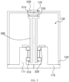
- FIG. 2 schematically illustrates a cross-sectional view a mounting bracket according to another exemplary embodiment of the present disclosure.
- the structure, the connecting manner and the functional relationship of main components of the mounting bracket according to the exemplary embodiment of the present disclosure are substantially the same as those of the schemes in the first embodiment.
- the content, different from the first embodiment, in the second embodiment of the mounting bracket provided in the present disclosure is described in detail with reference to the accompanying drawings.
- a second magnetic element 510 and a first magnetic element 520 have plate-shaped structures, and a polarity of the second magnetic element 510 and a polarity of the first magnetic element 520 are opposite, so that a magnetic attractive force is generated between the two magnetic elements in an axial direction of a rotating shaft 200.
- the magnetic attractive force includes force which is applied to the second magnetic element 410 (indirectly applied to the rotating shaft 200) in the radial direction of the rotating shaft 200 along the axis thereof, thereby positioning the rotating shaft 200 on the axis.
- one of the first magnetic element and the second magnetic element may have a plate-shaped structure. This is not limited by the embodiment.
- an upper end of the rotating shaft 200 can horizontally extend to form a platform 220, and accordingly, the second magnetic element 510 is arranged on the platform 220.
- the upper end of the rotating shaft can alternatively be equipped with a second magnetic element of a plate-shaped structure through another structure, for example, a groove. This is not limited in the embodiment.
- a position, corresponding to the rotating shaft 200, on an outer surface of a top of the housing can be provided with a groove 122, and accordingly, the first magnetic element 520 is arranged in the groove 122.
- a position, corresponding to the rotating shaft, on the outer surface of the top of the housing can alternatively be equipped with a first magnetic element of a plate-shaped structure in another manner.
- the groove is not provided, and the first magnetic element is directly arranged on the outer surface of the housing.
- the first magnetic part may alternatively be arranged on an inner surface of a top of the housing or arranged in the groove provided on the inner surface on the top of the housing. This is not limited in the embodiment.
- the second magnetic element 510 may have a circular-disc-shaped structure, and an axis of the circular disc coincides with that of the rotating shaft 200.
- the first magnetic element 520 may have a circular-disc-shaped structure, and an axis of the circular disc coincides with that of the rotating shaft 200.
- an orthographic projection of the second magnetic element 510 in a horizontal direction completely coincides with an orthographic projection of the first magnetic element 520 in the horizontal direction. That is, a diameter of a corresponding circle of a cross section of the second magnetic element 510 is equal to that of a corresponding circle of a cross section of the first magnetic element 520.
- the magnetic positioning assembly of the mounting bracket provided in the present disclosure may alternatively include a plurality of second magnetic elements or a plurality of first magnetic elements.
- the magnetic positioning assembly includes a plurality of second magnetic elements and one first magnetic element, where the plurality of second magnetic elements may be arranged at intervals along a circular path, and force in a radial direction of a rotating shaft is separately generated between the plurality of second magnetic elements and the first magnetic element.
- the magnetic positioning assembly includes a plurality of first magnetic elements and one second magnetic element, where the plurality of first magnetic elements may be arranged at intervals along a perimeter of a circle, and force in a radial direction of a rotating shaft is respectively generated between the plurality of first elements and the second magnetic element.
- the magnetic positioning assembly includes a plurality of second magnetic elements and a plurality of first magnetic elements, and force in a radial direction of the rotating shaft is respectively generated between the plurality of second elements and the plurality of first magnetic elements.
- the mounting bracket according to the present disclosure may alternatively include a plurality of magnetic positioning assemblies which may be vertically arranged at intervals in an axial direction of the rotating shaft.
- the two magnetic positioning assemblies may be respectively arranged between the upper end of the rotating shaft and the top of the housing and between the lower end of the rotating shaft and the bottom of the housing.
- the self-propelled robot includes a base body and a laser distance sensor, and further includes the mounting bracket according to the present disclosure and described in detail in the foregoing embodiments.
- the base body may include a housing or another structure of the self-propelled robot, wherein the mounting bracket is mounted on the base body through the housing.
- the laser distance sensor is arranged on the rotating shaft of the mounting bracket, so that the laser distance sensor is mounted on the base body of the robot through the mounting bracket.
- the laser distance sensor may be mounted on a top of the self-propelled robot through the mounting bracket, and rotation of the laser distance sensor can be realized through rotation of the mounting bracket, so that the laser distance sensor measures a distance between the self-propelled robot and an obstacle nearby.
- the laser distance sensor may alternatively be mounted on a side surface of the self-propelled robot through the mounting bracket. This is not limited in the present disclosure.
- the magnetic positioning assembly of the mounting bracket disclosed in the embodiments of the present disclosure includes a second magnetic element and a first magnetic element, which are respectively arranged on the rotating shaft and the housing; and in a case that the rotating shaft deviates from an axis in the rotation process, force in the radial direction of the rotating shaft is generated between the second magnetic element and the first magnetic element.
- the mounting bracket can position the rotating shaft with respect to the housing through force in the radial direction of the rotating shaft, so that offset and jitter generated during rotation of the laser distance sensor can be effectively alleviated, thereby improving reliability and precision of products, prolonging service lives of the products, and the like.
Landscapes
- Engineering & Computer Science (AREA)
- Physics & Mathematics (AREA)
- General Physics & Mathematics (AREA)
- Mechanical Engineering (AREA)
- Radar, Positioning & Navigation (AREA)
- Computer Networks & Wireless Communication (AREA)
- Remote Sensing (AREA)
- Robotics (AREA)
- Electromagnetism (AREA)
- General Engineering & Computer Science (AREA)
- Optics & Photonics (AREA)
- Magnetic Bearings And Hydrostatic Bearings (AREA)
- Manipulator (AREA)
- Transmission And Conversion Of Sensor Element Output (AREA)
Abstract
Description
- The present disclosure claims priority to
Chinese Patent Application No. 202010547861.7 filed on June 16, 2020 - The present disclosure relates to the field of robot technologies, and in particular, to a mounting bracket and a self-propelled robot.
- With the development of technologies, various robots with intelligent systems, such as a cleaning robot, a mopping robot, a vacuum collector and a lawnmower emerge. These robots can automatically travel in a certain area and carry out cleaning or clearing without operations of users. A robot is usually equipped with a laser distance sensor (LDS), which is configured to measure distances between the robot and various obstacles in an area in which the robot is located, so that the robot creates a map of the area, avoids the obstacles and locates itself in the area.
- At present, most of LDSs are rotatably mounted on robots, and distances between the robots and nearby obstacles can be measured by rotating the LDSs.
- A technical problem to be solved in the present disclosure is how to provide a mounting bracket which can alleviate an offset and jitter during rotation of a laser distance sensor.
- Another technical problem to be solved in the present disclosure is how to provide a self-propelled robot having the mounting bracket.
- Additional aspects and advantages of the present disclosure will be set forth in part in the following descriptions and, in part, will be obvious from the descriptions, or may be learned by practice of the present disclosure.
- To achieve the objective, the following technical solutions are adopted in the present disclosure:
An embodiment of the present disclosure provides a mounting bracket, configured to rotatably mount a laser distance sensor on a base body. The mounting bracket includes a housing, a rotating shaft and a magnetic positioning assembly. The housing is provided with an inner cavity. - The rotating shaft is vertically and rotatably arranged in the inner cavity. The magnetic positioning assembly includes a first magnetic element and a second magnetic element which are respectively arranged on the housing and the rotating shaft. The laser distance sensor is arranged on the rotating shaft; and in a case that the rotating shaft deviates from an axis, the mounting bracket is configured to generate a force between the first magnetic element and the second magnetic element in a radial direction of the rotating shaft so that the rotating shaft is positioned with respect to the housing.
- According to an embodiment of the present disclosure, the first magnetic element is arranged at a position, corresponding to an upper end of the rotating shaft, of the housing, and the second magnetic element is arranged at the upper end of the rotating shaft.
- According to an embodiment of the present disclosure, the first magnetic element is symmetrically arranged relative to the axis of the rotating shaft and the second magnetic element is symmetrically arranged relative to the axis of the rotating shaft.
- According to an embodiment of the present disclosure, a polarity of the first magnetic element and a polarity of the second magnetic element are identical.
- According to an embodiment of the present disclosure, the first magnetic element has an annular structure, an inner diameter of the first magnetic element is greater than an outer diameter of the second magnetic element, and the first magnetic element is sleeved on the second magnetic element.
- According to an embodiment of the present disclosure, an inner surface of a top of the housing is provided with a first bump that bumps downwards, and the first magnetic element is attached to the first bump.
- According to an embodiment of the present disclosure, the second magnetic element has an annular structure, and an axis of the annular structure coincides with the axis of the rotating shaft.
- According to an embodiment of the present disclosure, the upper end of the rotating shaft is provided with a second bump that bumps upwards, and the second magnetic element is arranged around the second bump.
- According to an embodiment of the present disclosure, a polarity of the first magnetic element and a polarity of the second magnetic element are opposite.
- According to an embodiment of the present disclosure, the first magnetic element has a plate-shaped structure.
- According to an embodiment of the present disclosure, the second magnetic element has a plate-shaped structure.
- According to an embodiment of the present disclosure, the upper end of the rotating shaft horizontally extends to form a platform, and the second magnetic element is arranged on the platform; and/or a groove is provided at a position, corresponding to the rotating shaft, of an outer surface of a top of the housing, and the first magnetic element is arranged in the groove. An embodiment of the present disclosure provides a self-propelled robot, including a base body and a laser distance sensor. The self-propelled robot further includes the mounting bracket described in the foregoing embodiments of the present disclosure, which is mounted on the base body through the housing. The laser distance sensor is arranged on the rotating shaft of the mounting bracket.
- It is known from the foregoing technical solutions that the advantages and the positive effects of the mounting bracket and the self-propelled robot disclosed in the embodiments of the present disclosure are at least as follows:
The laser distance sensor is arranged on the rotating shaft of the mounting bracket disclosed in the embodiments of the present disclosure, and the rotating shaft deviates from the axis in a rotation process, the mounting bracket can position the rotating shaft with respect to the housing through the force in the radial direction of the rotating shaft, so that an offset and jitter generated during rotation of the laser distance sensor can be effectively alleviated, thereby improving reliability and precision of the products, prolonging service lives of the products, and the like. -
-
FIG. 1 illustrates a cross-sectional view of a mounting bracket according to an embodiment of the present disclosure; and -
FIG. 2 illustrates a cross-sectional view of a mounting bracket according to another embodiment of the present disclosure. - Reference numerals of the drawings are as follows:
- 110. first case;
- 111. shaft seat;
- 120. second case;
- 121. first bump;
- 122. groove;
- 130. inner cavity;
- 200. rotating shaft;
- 210. second bump;
- 220. platform;
- 310. first bearing;
- 320. second bearing;
- 410. second magnetic element;
- 420. first magnetic element;
- 510. second magnetic element; and
- 520. second magnetic element.
- Exemplary embodiments of the present invention are described in more detail with reference to the accompanying drawings. However, the exemplary embodiments can be implemented in various forms, and should not be construed as being limited to the embodiments set forth herein; on the contrary, these embodiments are provided so that the present disclosure can be more comprehensive and complete, and fully convey the concept of the exemplary embodiments to a person skilled in the art. Same reference numerals in the accompanying drawings denote same or similar structures, and thus detailed descriptions thereof are omitted.
-
FIG. 1 schematically illustrates a cross-sectional view of a mounting bracket provided in an embodiment of the present disclosure according to an exemplary embodiment. In the exemplary embodiment, the mounting bracket according to the present disclosure is illustrated through an example in which the mounting bracket is applied to a robot such as a sweeping robot. One of ordinary skill in the art can easily understand that various modifications, addition, replacement, deletion or other changes made to the following specific embodiments for applying related design of the embodiments of the present disclosure to other robots or equipment shall fall within the scope of the principle of the mounting bracket according to the embodiments of the present disclosure. - As illustrated in
FIG. 1 , in the embodiment of the present, the mounting bracket according to the present disclosure can be configured to rotatably mount a laser distance sensor on a base body (for example, a housing of a sweeping robot). The mounting bracket includes a housing, arotating shaft 200 and a magnetic positioning assembly. The structure, the connecting way and the functional relationship of main components of the mounting bracket according to the embodiment of the present disclosure are described in detail with reference toFIG. 1 . - As illustrated in
FIG. 1 , in the embodiment, the housing is provided with aninner cavity 130. In the embodiment of the present disclosure, theinner cavity 130 may be a closed space formed by the housing which can be made of a material capable of emitting light through the laser distance sensor. Therotating shaft 200 is vertically arranged and is rotatably arranged in theinner cavity 130. The magnetic positioning assembly includes two magnetic elements which are respectively attached to the housing and therotating shaft 200. For ease of understanding and description, the magnetic element arranged on therotating shaft 200 is referred to as the second magnetic element 410 and the magnetic element arranged on the housing is referred to as the first magnetic element 420. The laser distance sensor is attached to therotating shaft 200, the mounting bracket according to the present disclosure may position therotating shaft 200 with respect to the housing through a magnetic force between the two magnetic elements. Specifically, in a case that therotating shaft 200 deviates from an axis, the technical solution according to the embodiment of the present disclosure can position thepositioning shaft 200 with respect to the housing through a force in a radial direction of therotating shaft 200 between the first magnetic element 420 and the second magnetic element 410. Through the scheme, the mounting bracket according to the embodiment of the present disclosure can effectively alleviate an offset and jitter generated during rotation of the laser distance sensor, thereby improving reliability and precision of the products, prolonging service lives of the products, and the like. According to the technical solution provided in the embodiment of the present disclosure, the principle of attraction of opposite magnetisms and repellence of identical magnetisms between the second magnetic element and the first magnetic element can be utilized to generate a force in the radial direction of therotating shaft 200 to position therotating shaft 200; and moreover, therotating shaft 200 is not in direct contact with a structure such as a case (for example, a second case 120), further reducing friction between components. - Optionally, as illustrated in
FIG. 1 , in the embodiment, the housing can include afirst case 110 and thesecond case 120. Specifically, thesecond case 120 is detachably arranged on thefirst case 110, and thefirst case 110 and thesecond case 120 cooperatively form a housing and defines theinner cavity 130 of the housing. On this basis, a lower end of therotating shaft 200 is rotatably arranged on thefirst case 110. In another embodiment, the housing can alternatively have another structure, such as an integrated structure. Furthermore, in a case that the housing includes the first case and the second case, the two housings are not limited to the vertical combination way in the embodiment, for example, can be juxtaposed. In addition, an upper end of the rotating shaft may be rotatably engaged with the housing. This is not limited in the embodiment. - Further, as illustrated in
FIG. 1 , based on the scheme that a lower end of therotating shaft 200 is rotatably arranged on thefirst case 110, in the embodiment, an inner surface of a bottom of thefirst case 110 can be equipped with ashaft seat 111. On this basis, the lower end of therotating shaft 200 can be rotatably arranged on theshaft seat 111 through a bearing. - Furthermore, as illustrated in
FIG. 1 , based on the scheme that therotating shaft 200 is arranged on theshaft seat 111 through the bearing, in the embodiment, a plurality of bearings can be arranged between therotating shaft 200 and theshaft seat 111, and the embodiment is described through an example in which there are two bearings. For ease of understanding and description, the two bearings are respectively defined as afirst bearing 310 and asecond bearing 320 in the specification. The two bearings are arranged between therotating shaft 200 and theshaft seat 111 at intervals in a vertical direction (namely, an axial direction of the rotating shaft 200), and thesecond bearing 320 is located above thefirst bearing 310. - Optionally, as illustrated in
FIG. 1 , in the embodiment, a shaft cavity which extends along the axis is defined inside therotating shaft 200. - Optionally, as illustrated in
FIG. 1 , in the embodiment, the first magnetic element 420 can be symmetrically arranged relative to the axis. For example, in a case that the first magnetic element 420 has a circular-ring-shaped structure, a center of a circle corresponding to the first magnetic element 420 is positioned on therotating shaft 200 or an extending line thereof. For another example, in a case that the first magnetic element 420 has a regularly-polygonal plate-shaped structure, a geometric center thereof is positioned on therotating shaft 200 or the extending line thereof. That is, the first magnetic element 420 has a ring-shaped or plate-shaped structure in central symmetry, wherein the central symmetry indicates a symmetrical shape with respect to its geometric center positioned on therotating shaft 200 or the extending line thereof. - Optionally, as illustrated in
FIG. 1 , in the embodiment, the second magnetic element 410 may be symmetrically arranged with respect to the axis. For example, in a case that the second magnetic element 410 has a circular-ring-shaped structure, a circle center of a circle corresponding to the second magnetic element is positioned on therotating shaft 200 or an extending line thereof. For another example, in a case that the second magnetic element 410 has a regularly-polygonal plate-shaped structure, a geometric center thereof is positioned on therotating shaft 200 or the extending line thereof. That is, the second magnetic element 410 has a ring-shaped or plate-shaped structure in central symmetry, wherein the central symmetry indicates a symmetrical shape with respect to its geometric center positioned on therotating shaft 200 or the extending line thereof. - Optionally, as illustrated in
FIG. 1 , in the embodiment, the magnetic positioning assembly is arranged between the housing and the upper end of therotating shaft 200. Specifically, among the two magnetic elements of the magnetic positioning assembly, the second magnetic element 410 is arranged at the upper end of therotating shaft 200, and the first magnetic element 420 is arranged on a position, corresponding to the upper end of therotating shaft 200, of the housing. - Furthermore, as illustrated in
FIG. 1 , based on the scheme that the magnetic positioning assembly is arranged between the housing and the upper end of therotating shaft 200, in the embodiment, the second magnetic element 410 and the first magnetic element 420 have annular structures respectively, axes of which coincide with the axis. A polarity of the second magnetic element 410 and a polarity of the first magnetic element 420 are identical, so that magnetic repulsive force is generated between the second magnetic element 410 and the first magnetic element 420. On this basis, an outer diameter of the second magnetic element 410 may be less than an inner diameter of the first magnetic element 420, so that the first magnetic element 420 may be arranged around the second magnetic element 410; and a clearance is formed between the inner ring surface of the first magnetic element 420 and the outer ring surface of the second magnetic element 410. Therefore, in a case that therotating shaft 200 deviates from the axis, the magnetic repulsive force includes force which is applied to the second magnetic element 410 (indirectly applied to the rotating shaft 200) in the radial direction of therotating shaft 200 along the axis thereof, thereby positioning therotating shaft 200 on the axis. - Furthermore, based on the scheme that the second magnetic element 410 has an annular structure, in the embodiment, the second magnetic element 410 may have a circular-ring-shaped structure. In another embodiment, alternatively, the second magnetic element may have a polygonal annular structure or the like. This is not limited in the embodiment.
- Furthermore, based on the scheme that the first magnetic element 420 has an annular structure, in the embodiment, the first magnetic element 420 may have a circular-ring-shaped structure. In another embodiment, alternatively, the first magnetic element may have a polygonal annular structure or the like. This is not limited in the embodiment.
- Furthermore, as illustrated in
FIG. 1 , based on the scheme that the magnetic positioning assembly is arranged between the housing and the upper end of therotating shaft 200 and the scheme that the second magnetic element 410 has an annular structure, in the embodiment, the upper end of therotating shaft 200 may be provided with asecond bump 210 that bumps upwards, and accordingly, the second magnetic element 410 is arranged around thesecond bump 210. - Furthermore, based on the scheme that the upper end of the
rotating shaft 200 is provided with thesecond bump 210 that bumps upwards and the scheme that the second magnetic element 410 has a circular-ring-shaped structure, in the embodiment, thesecond bump 210 may be cylindrical, and the second magnetic element 410 is arranged around an outer ring surface of thesecond bump 210. In addition, a diameter of a circle corresponding to a cross section of thesecond bump 210 may be equal to or slightly greater than an inner diameter of the second magnetic element 410, so that the second magnetic element 410 is arranged around thesecond bump 210 in a tight fit or interference fit mode, and the second magnetic element 410 is further prevented from radial wobble and axial jolt in a high-speed rotation of therotating shaft 200. In another embodiment, in a case that the second magnetic element has a polygonal annular structure, the second bump may also have a corresponding polyprism-shaped structure. - Furthermore, as illustrated in
FIG. 1 , based on the scheme that the magnetic positioning assembly is arranged between the housing and the upper end of therotating shaft 200 and the scheme that the first magnetic element 420 has an annular structure, in the embodiment, the lower surface of the top of the housing (for example, the second case 120) can be provided with afirst bump 121 that bumps downwards (that is, facing the rotating shaft 200), and accordingly, the first magnetic element 420 is arranged around thefirst bump 121. - Furthermore, based on the scheme that the lower surface of the top of the housing is provided with a
first bump 121 and the scheme that the first magnetic element 420 has a circular-ring-shaped structure, in the embodiment, thefirst bump 121 may have a shape of a circular ring, and the first magnetic element 420 is arranged around the inner ring surface of thefirst bump 121. In addition, a diameter of a circle corresponding to the cross section of thefirst bump 121 may be equal to or slightly less than an inner diameter of the first magnetic element 420, so that the first magnetic element 420 is arranged around the secondfirst structure 121 in a tight fit or interference fit, and the combination degree between the first magnetic element 420 and the housing is further improved. In another embodiment, in a case that the first magnetic element has a polygonal annular structure, the second bump may also have a corresponding polygonal ring-shaped structure. - It should be noted that in another embodiment, based on the scheme that both the second magnetic element and the first magnetic element have ring-shaped structures, the second bump may also have a shape of a circular ring, and the outer ring of the second magnetic element is sleeved by the inner ring surface of the second bump. Alternatively, the first bump is cylindrical, and the inner ring of the first magnetic element is arranged around the outer ring surface of the first bump. This is not limited in the embodiment.
-
FIG. 2 schematically illustrates a cross-sectional view a mounting bracket according to another exemplary embodiment of the present disclosure. The structure, the connecting manner and the functional relationship of main components of the mounting bracket according to the exemplary embodiment of the present disclosure are substantially the same as those of the schemes in the first embodiment. The content, different from the first embodiment, in the second embodiment of the mounting bracket provided in the present disclosure is described in detail with reference to the accompanying drawings. - As illustrated in
FIG. 2 , in the embodiment, a secondmagnetic element 510 and a firstmagnetic element 520 have plate-shaped structures, and a polarity of the secondmagnetic element 510 and a polarity of the firstmagnetic element 520 are opposite, so that a magnetic attractive force is generated between the two magnetic elements in an axial direction of arotating shaft 200. - Therefore, when the
rotating shaft 200 deviates from an axis, the magnetic attractive force includes force which is applied to the second magnetic element 410 (indirectly applied to the rotating shaft 200) in the radial direction of therotating shaft 200 along the axis thereof, thereby positioning therotating shaft 200 on the axis. In another embodiment, alternatively, one of the first magnetic element and the second magnetic element may have a plate-shaped structure. This is not limited by the embodiment. - Furthermore, as illustrated in
FIG. 2 , based on the scheme that the secondmagnetic element 510 is of a plate-shaped structure, in the embodiment, an upper end of therotating shaft 200 can horizontally extend to form aplatform 220, and accordingly, the secondmagnetic element 510 is arranged on theplatform 220. In another embodiment, the upper end of the rotating shaft can alternatively be equipped with a second magnetic element of a plate-shaped structure through another structure, for example, a groove. This is not limited in the embodiment. - Furthermore, as illustrated in
FIG. 2 , based on the scheme that the secondmagnetic element 520 has a plate-shaped structure, in the embodiment, a position, corresponding to therotating shaft 200, on an outer surface of a top of the housing can be provided with agroove 122, and accordingly, the firstmagnetic element 520 is arranged in thegroove 122. In another embodiment, a position, corresponding to the rotating shaft, on the outer surface of the top of the housing can alternatively be equipped with a first magnetic element of a plate-shaped structure in another manner. For example, the groove is not provided, and the first magnetic element is directly arranged on the outer surface of the housing. In addition, the first magnetic part may alternatively be arranged on an inner surface of a top of the housing or arranged in the groove provided on the inner surface on the top of the housing. This is not limited in the embodiment. - Furthermore, based on the scheme that the second
magnetic element 510 has a plate-shaped structure, in the embodiment, the secondmagnetic element 510 may have a circular-disc-shaped structure, and an axis of the circular disc coincides with that of therotating shaft 200. - Furthermore, based on the scheme that the first
magnetic element 520 has a plate-shaped structure, in the embodiment, the firstmagnetic element 520 may have a circular-disc-shaped structure, and an axis of the circular disc coincides with that of therotating shaft 200. - Furthermore, based on the scheme that both the second
magnetic element 510 and the firstmagnetic element 520 have circular-disc-shaped structures respectively, in the embodiment, an orthographic projection of the secondmagnetic element 510 in a horizontal direction completely coincides with an orthographic projection of the firstmagnetic element 520 in the horizontal direction. That is, a diameter of a corresponding circle of a cross section of the secondmagnetic element 510 is equal to that of a corresponding circle of a cross section of the firstmagnetic element 520. - It should be noted that in another embodiment, the magnetic positioning assembly of the mounting bracket provided in the present disclosure may alternatively include a plurality of second magnetic elements or a plurality of first magnetic elements. For example, on the basis of the first embodiment illustrated in
FIG. 1 , the magnetic positioning assembly includes a plurality of second magnetic elements and one first magnetic element, where the plurality of second magnetic elements may be arranged at intervals along a circular path, and force in a radial direction of a rotating shaft is separately generated between the plurality of second magnetic elements and the first magnetic element. Alternatively, the magnetic positioning assembly includes a plurality of first magnetic elements and one second magnetic element, where the plurality of first magnetic elements may be arranged at intervals along a perimeter of a circle, and force in a radial direction of a rotating shaft is respectively generated between the plurality of first elements and the second magnetic element. Alternatively, the magnetic positioning assembly includes a plurality of second magnetic elements and a plurality of first magnetic elements, and force in a radial direction of the rotating shaft is respectively generated between the plurality of second elements and the plurality of first magnetic elements. - In addition, in another embodiment, the mounting bracket according to the present disclosure may alternatively include a plurality of magnetic positioning assemblies which may be vertically arranged at intervals in an axial direction of the rotating shaft. For example, in a case that there are two magnetic positioning assemblies, the two magnetic positioning assemblies may be respectively arranged between the upper end of the rotating shaft and the top of the housing and between the lower end of the rotating shaft and the bottom of the housing.
- It should be noted herein that the mounting brackets described in the specification are merely several examples of various mounting brackets which can adopt the principle of the present disclosure. It should be clearly understood that the principle of the present disclosure is not only limited to any detail or any part of the mounting bracket illustrated in the accompanying drawings or described in the specification.
- Based on the detailed descriptions of two exemplary embodiments of the mounting bracket provided in the present disclosure, one exemplary embodiment of a self-propelled robot provided in the present disclosure is briefly described below.
- In the embodiment, the self-propelled robot according to the present disclosure includes a base body and a laser distance sensor, and further includes the mounting bracket according to the present disclosure and described in detail in the foregoing embodiments. Specifically, the base body may include a housing or another structure of the self-propelled robot, wherein the mounting bracket is mounted on the base body through the housing. Accordingly, the laser distance sensor is arranged on the rotating shaft of the mounting bracket, so that the laser distance sensor is mounted on the base body of the robot through the mounting bracket. In the embodiment of the present disclosure, the laser distance sensor may be mounted on a top of the self-propelled robot through the mounting bracket, and rotation of the laser distance sensor can be realized through rotation of the mounting bracket, so that the laser distance sensor measures a distance between the self-propelled robot and an obstacle nearby. In another embodiment of the present disclosure, the laser distance sensor may alternatively be mounted on a side surface of the self-propelled robot through the mounting bracket. This is not limited in the present disclosure.
- It should be noted that the self-propelled robot illustrated in the accompanying drawings and described in the specification are merely an example of various robots which can adopt the principle of the present disclosure. It should be clearly understood that the principle of the present disclosure is not only limited to any detail or any part of the self-propelled robot illustrated in the accompanying drawings or described in the specification.
- In summary, the magnetic positioning assembly of the mounting bracket disclosed in the embodiments of the present disclosure includes a second magnetic element and a first magnetic element, which are respectively arranged on the rotating shaft and the housing; and in a case that the rotating shaft deviates from an axis in the rotation process, force in the radial direction of the rotating shaft is generated between the second magnetic element and the first magnetic element. Through the scheme, in a case that the laser distance sensor is arranged on the rotating shaft of the mounting bracket according to the present disclosure, the mounting bracket can position the rotating shaft with respect to the housing through force in the radial direction of the rotating shaft, so that offset and jitter generated during rotation of the laser distance sensor can be effectively alleviated, thereby improving reliability and precision of products, prolonging service lives of the products, and the like.
- Although the present disclosure has been described with reference to a few typical embodiments, it should be understood that the terms used herein are meant to be illustrative and not restrictive. Because the present disclosure can be implemented in various forms without departing from the spirit or gist of the present disclosure, it should be understood that the foregoing embodiments are not limited to any of the foregoing details, but should be broadly explained within the spirit and scope defined by the appended claims. Therefore, all changes and modifications that fall within the scope of the claims or equivalents thereof shall be covered by the appended claims.
Claims (15)
- A mounting bracket, configured to rotatably mount a laser distance sensor on a base body, and comprising:a housing, which is provided with an inner cavity;a rotating shaft, which is vertically and rotatably arranged in the inner cavity; anda magnetic positioning assembly, comprising a first magnetic element and a second magnetic element which are respectively attached to the housing and the rotating shaft;wherein the laser distance sensor is attached to the rotating shaft; and when the rotating shaft deviates from an axis, the mounting bracket is configured to generate a force between the first magnetic element and the second magnetic element in a radial direction of the rotating shaft for positioning relative positions of the rotating shaft and the housing.
- The mounting bracket according to claim 1, wherein the first magnetic element is arranged at a position, corresponding to an upper end of the rotating shaft, of the housing, and the second magnetic element is arranged at the upper end of the rotating shaft.
- The mounting bracket according to claim 1 or 2, wherein the first magnetic element is symmetrically arranged relative to the axis of the rotating shaft and the second magnetic element is symmetrically arranged relative to the axis of the rotating shaft.
- The mounting bracket according to claim 3, wherein a polarity of the first magnetic element and a polarity of the second magnetic element are identical.
- The mounting bracket according to claim 4, wherein the first magnetic element has an annular structure, an inner diameter of the first magnetic element is greater than an outer diameter of the second magnetic element, and the first magnetic element is arranged around the second magnetic element.
- The mounting bracket according to claim 5, wherein an inner surface of a top of the housing is provided with a first bump that bumps downwards, and the first magnetic element is attached to the first bump.
- The mounting bracket according to claim 5, wherein the second magnetic element has an annular structure, and an axis of the annular structure coincides with the axis.
- The mounting bracket according to claim 7, wherein the upper end of the rotating shaft is provided with a second bump that bumps upwards, and the second magnetic element is arranged around the second bump.
- The mounting bracket according to claim 3, wherein a polarity of the first magnetic element and a polarity of the second magnetic element are opposite.
- The mounting bracket according to claim 9, wherein the first magnetic element has a plate-shaped structure.
- The mounting bracket according to claim 10, wherein a position, corresponding to the rotating shaft, of an outer surface of a top of the housing is provided with a groove, and the first magnetic element is arranged in the groove.
- The mounting bracket according to claim 10, wherein the second magnetic element has a plate-shaped structure.
- The mounting bracket according to claim 12, wherein the upper end of the rotating shaft horizontally extends to form a platform, and the second magnetic element is attached to the platform.
- The mounting bracket according to claim 1, wherein the housing comprises:a first case; anda second case, detachably arranged on the first case, whereinthe first case and the second case are enclosed to define the inner cavity; anda lower end of the rotating shaft is rotatably arranged on the first case.
- A self-propelled robot, comprising a base body and a laser distance sensor, and further comprising:a mounting bracket according to any one of claims 1 to 14, which is mounted on the base body through the housing, whereinthe laser distance sensor is arranged on the rotating shaft of the mounting bracket.
Applications Claiming Priority (2)
| Application Number | Priority Date | Filing Date | Title |
|---|---|---|---|
| CN202010547861.7A CN111568301B (en) | 2020-06-16 | 2020-06-16 | Mounting bracket and robot |
| PCT/CN2021/087779 WO2021253959A1 (en) | 2020-06-16 | 2021-04-16 | Installation support and autonomous mobile robot |
Publications (2)
| Publication Number | Publication Date |
|---|---|
| EP4129141A1 true EP4129141A1 (en) | 2023-02-08 |
| EP4129141A4 EP4129141A4 (en) | 2024-05-22 |
Family
ID=72116526
Family Applications (1)
| Application Number | Title | Priority Date | Filing Date |
|---|---|---|---|
| EP21826985.0A Pending EP4129141A4 (en) | 2020-06-16 | 2021-04-16 | Installation support and autonomous mobile robot |
Country Status (4)
| Country | Link |
|---|---|
| US (1) | US11691266B2 (en) |
| EP (1) | EP4129141A4 (en) |
| CN (1) | CN111568301B (en) |
| WO (1) | WO2021253959A1 (en) |
Families Citing this family (2)
| Publication number | Priority date | Publication date | Assignee | Title |
|---|---|---|---|---|
| CN111568301B (en) * | 2020-06-16 | 2025-07-18 | 北京石头世纪科技股份有限公司 | Mounting bracket and robot |
| CN116540399A (en) * | 2022-01-25 | 2023-08-04 | 宜宾市极米光电有限公司 | Rotary light path adjusting device and optical equipment |
Family Cites Families (25)
| Publication number | Priority date | Publication date | Assignee | Title |
|---|---|---|---|---|
| KR20040018603A (en) * | 2002-08-23 | 2004-03-04 | 삼성전자주식회사 | Cleaning device |
| US7152267B2 (en) * | 2003-09-25 | 2006-12-26 | Bryan Kaleta | Floor sweeper |
| KR200341078Y1 (en) * | 2003-10-14 | 2004-02-11 | 이부락 | Magnet Bearing |
| JP2006314677A (en) * | 2005-05-16 | 2006-11-24 | Funai Electric Co Ltd | Self-propelled vacuum cleaner |
| JP4544135B2 (en) * | 2005-11-10 | 2010-09-15 | 株式会社デンソー | Rotation angle detection unit |
| US7992312B2 (en) * | 2008-07-10 | 2011-08-09 | Krasko Michael E | Positioning system for laser alignment tools |
| JP5899090B2 (en) * | 2012-09-14 | 2016-04-06 | 日立オートモティブシステムズステアリング株式会社 | Torque sensor |
| US8972061B2 (en) * | 2012-11-02 | 2015-03-03 | Irobot Corporation | Autonomous coverage robot |
| JP5850259B2 (en) * | 2012-11-28 | 2016-02-03 | 株式会社デンソー | Rotating electric machine |
| GB2535378B (en) * | 2013-12-27 | 2017-01-25 | Halliburton Energy Services Inc | Mounting bracket for strain sensor |
| EP3035076B1 (en) | 2014-12-17 | 2020-08-19 | Leica Geosystems AG | Measuring device with positioning device |
| US9682483B1 (en) * | 2015-03-19 | 2017-06-20 | Amazon Technologies, Inc. | Systems and methods for removing debris from warehouse floors |
| CN204464170U (en) * | 2015-03-31 | 2015-07-08 | 黄志恒 | Multi-direction sensor |
| CN205521503U (en) * | 2016-02-01 | 2016-08-31 | 江苏亚太霍夫曼金属打印科技有限公司 | Anticollision mechanism of robot |
| US11673272B2 (en) * | 2016-12-23 | 2023-06-13 | Gecko Robotics, Inc. | Inspection robot with stability assist device |
| KR101918994B1 (en) * | 2017-01-02 | 2019-02-08 | 엘지전자 주식회사 | Lawn mower robot |
| US10343276B2 (en) * | 2017-07-12 | 2019-07-09 | Saudi Arabian Oil Company | Compact magnetic crawler vehicle with anti-rocking supports |
| CN107670135A (en) * | 2017-09-18 | 2018-02-09 | 上海交通大学医学院附属上海儿童医学中心 | A kind of single fulcrum magnetomotive drive-type centrifugal pump and its drive component |
| JP7161346B2 (en) * | 2018-08-30 | 2022-10-26 | 日本電産サンキョー株式会社 | Shake correction device, optical unit with shake correction function, and manufacturing method thereof |
| US11331818B2 (en) * | 2018-10-11 | 2022-05-17 | Foster-Miller, Inc. | Remotely controlled packable robot |
| KR102677181B1 (en) * | 2019-01-02 | 2024-06-20 | 엘지전자 주식회사 | mobile robot |
| CN209717712U (en) * | 2019-03-28 | 2019-12-03 | 深圳市神州云海智能科技有限公司 | Rotation drive device and robot for robot head |
| CN212729668U (en) * | 2020-06-16 | 2021-03-19 | 北京石头世纪科技股份有限公司 | Mounting bracket and robot |
| CN111568301B (en) * | 2020-06-16 | 2025-07-18 | 北京石头世纪科技股份有限公司 | Mounting bracket and robot |
| US11446718B2 (en) * | 2020-06-22 | 2022-09-20 | Toyota Motor North America, Inc. | Systems and methods for automatically cleaning wheels |
-
2020
- 2020-06-16 CN CN202010547861.7A patent/CN111568301B/en active Active
-
2021
- 2021-04-16 WO PCT/CN2021/087779 patent/WO2021253959A1/en not_active Ceased
- 2021-04-16 EP EP21826985.0A patent/EP4129141A4/en active Pending
-
2022
- 2022-10-28 US US18/050,528 patent/US11691266B2/en active Active
Also Published As
| Publication number | Publication date |
|---|---|
| US20230075678A1 (en) | 2023-03-09 |
| WO2021253959A1 (en) | 2021-12-23 |
| US11691266B2 (en) | 2023-07-04 |
| EP4129141A4 (en) | 2024-05-22 |
| CN111568301A (en) | 2020-08-25 |
| CN111568301B (en) | 2025-07-18 |
Similar Documents
| Publication | Publication Date | Title |
|---|---|---|
| US11691266B2 (en) | Mounting bracket and self-propelled robot | |
| ES2882213T3 (en) | Rotating arc sensor | |
| JP2013100891A (en) | Bearing device and fan | |
| CN103620244A (en) | Thrust roller bearing | |
| CN116750431A (en) | A magnetic levitation roller device | |
| JP6918698B2 (en) | Industrial robot | |
| CN212729668U (en) | Mounting bracket and robot | |
| CN107785284B (en) | Cover opening mechanism and semiconductor processing equipment | |
| KR101195368B1 (en) | Linear Stage Robot | |
| US7135798B2 (en) | Magnetic suspension bearing | |
| US3618403A (en) | Stop assembly for a gyroscope | |
| KR102536407B1 (en) | Shaft asembly with movable bearing housing | |
| CN100552238C (en) | Radiation fan | |
| CN214689846U (en) | Chassis and robot | |
| US4539612A (en) | Spindle bearing assembly for disk drive unit | |
| CN107956804A (en) | Bearing unit and motor | |
| CN224169045U (en) | Follow-up type robot welding gun cable support device | |
| CN109158802B (en) | Magnetic suspension damping stable connector for welding robot | |
| JP2025009598A (en) | Swivel caster structure | |
| JP2012057731A (en) | Ball bearing cage and ball bearing | |
| CN224262485U (en) | A swing arm structure for an automotive sensor | |
| CN117052807B (en) | Dustproof universal joint device | |
| CN223860720U (en) | Food processor | |
| CN114876957A (en) | Cage and rolling bearing | |
| KR20190004973A (en) | Roller bushing supporting substrate |
Legal Events
| Date | Code | Title | Description |
|---|---|---|---|
| STAA | Information on the status of an ep patent application or granted ep patent |
Free format text: STATUS: THE INTERNATIONAL PUBLICATION HAS BEEN MADE |
|
| PUAI | Public reference made under article 153(3) epc to a published international application that has entered the european phase |
Free format text: ORIGINAL CODE: 0009012 |
|
| STAA | Information on the status of an ep patent application or granted ep patent |
Free format text: STATUS: REQUEST FOR EXAMINATION WAS MADE |
|
| 17P | Request for examination filed |
Effective date: 20221104 |
|
| AK | Designated contracting states |
Kind code of ref document: A1 Designated state(s): AL AT BE BG CH CY CZ DE DK EE ES FI FR GB GR HR HU IE IS IT LI LT LU LV MC MK MT NL NO PL PT RO RS SE SI SK SM TR |
|
| DAV | Request for validation of the european patent (deleted) | ||
| DAX | Request for extension of the european patent (deleted) | ||
| REG | Reference to a national code |
Ref country code: DE Ref legal event code: R079 Free format text: PREVIOUS MAIN CLASS: A47L0011000000 Ipc: G01S0007481000 |
|
| A4 | Supplementary search report drawn up and despatched |
Effective date: 20240424 |
|
| RIC1 | Information provided on ipc code assigned before grant |
Ipc: G01B 11/02 20060101ALI20240418BHEP Ipc: G01B 5/00 20060101ALI20240418BHEP Ipc: A47L 11/40 20060101ALI20240418BHEP Ipc: A47L 11/00 20060101ALI20240418BHEP Ipc: G01S 17/931 20200101ALI20240418BHEP Ipc: G01S 17/42 20060101ALI20240418BHEP Ipc: G01S 7/497 20060101ALI20240418BHEP Ipc: G01S 7/481 20060101AFI20240418BHEP |
|
| STAA | Information on the status of an ep patent application or granted ep patent |
Free format text: STATUS: EXAMINATION IS IN PROGRESS |