EP4129070A1 - Bone removal device and bone removal method - Google Patents
Bone removal device and bone removal method Download PDFInfo
- Publication number
- EP4129070A1 EP4129070A1 EP20894947.9A EP20894947A EP4129070A1 EP 4129070 A1 EP4129070 A1 EP 4129070A1 EP 20894947 A EP20894947 A EP 20894947A EP 4129070 A1 EP4129070 A1 EP 4129070A1
- Authority
- EP
- European Patent Office
- Prior art keywords
- bone
- grip
- meat block
- guide
- gap
- Prior art date
- Legal status (The legal status is an assumption and is not a legal conclusion. Google has not performed a legal analysis and makes no representation as to the accuracy of the status listed.)
- Granted
Links
Images







Classifications
-
- A—HUMAN NECESSITIES
- A22—BUTCHERING; MEAT TREATMENT; PROCESSING POULTRY OR FISH
- A22C—PROCESSING MEAT, POULTRY, OR FISH
- A22C17/00—Other devices for processing meat or bones
- A22C17/004—Devices for deboning meat
Definitions
- the present invention relates to a bone removing device and a bone removing method of removing a bone to be removed such as a scapula from a meat block such as a pork block.
- Patent Literature 1 shows an example of a conventional bone removing device and, in this bone removing device, a constriction portion of a scapula is gripped by a portal chuck and the scapula is peeled off while a pork block is suspended and conveyed by a clamper.
- Patent Literature 1 Japanese Patent No. 4327099
- Patent Literature 1 In order to realize the device of Patent Literature 1, it was necessary to perform operations of photographing a pork block suspended from a clamper by X-ray, measuring a position of a bone in the pork block in an image analysis, bending the pork block in accordance with the position of the bone, gripping a scapula using a hand tool attached to a tip of a robot, and peeling off the scapula from the pork block.
- the pork block when the shape or size of the pork block is different from the usual one or when it is a soft pork block having meat softer than the usual one, the pork block cannot be bent properly according to the position of the bone or the position of the scapula is displaced so that the robot's hand tool cannot accurately grip the scapula in some cases. In such a case, it takes time and effort for an operator to manually adjust each part of a machine so that the bone removing operation can be smoothly performed.
- An object of the present invention is to provide a bone removing device and a bone removing method capable of stably performing a bone removing operation even when the shape, size, and softness of a meat block are different.
- the meat block is placed and conveyed on the transfer mechanism so that a part of the bone in the meat block is introduced into the gap between the first grip portion and the second grip portion.
- the drive mechanism moves the grip mechanism and peels off the bone from the meat block.
- the moving direction of the grip mechanism may be any direction if the bone can be peeled off from the meat block.
- the moving direction may be a direction away from the transfer mechanism.
- the drive mechanism may include a pressing mechanism which includes a pressing body disposed closer to the transfer mechanism than the first grip portion and the second grip portion and a pressing actuator moving the pressing body toward the transfer mechanism and presses the meat block by the pressing body when peeling off the bone from the meat block.
- the meat block since the meat block is pressed against the transfer mechanism by the pressing body when the grip mechanism is moved by the drive mechanism so that the bone is peeled off from the meat block, the meat block does not lift when peeling off the bone. As a result, there is an advantage that a stable peeling operation can be performed. Further, since the pressing body presses the meat block against the transfer mechanism, the position or shape of the meat block can also be standardized. This point also contributes to the stabilization of processing.
- the pressing body may be used to press the bone head of the bone remaining in the meat block. In that case, since the hard bone head is pressed, the meat block can be effectively fixed.
- the device of the above [1] or [2] may further include: a guide mechanism which includes first and second guide portions arranged along the transfer mechanism with a gap therebetween and guides a part of the bone in the meat block conveyed by the transfer mechanism to the gap between the first grip portion and the second grip portion through the gap.
- a guide mechanism which includes first and second guide portions arranged along the transfer mechanism with a gap therebetween and guides a part of the bone in the meat block conveyed by the transfer mechanism to the gap between the first grip portion and the second grip portion through the gap.
- the meat block when the meat block is placed on the transfer mechanism and a part of the bone of the meat block is disposed through the gap between the first guide portion and the second guide portion, the meat block moves while the part of the bone is guided through the gap between the first guide portion and the second guide portion by the conveying operation using the transfer mechanism and the part is introduced into the gap between the first grip portion and the second grip portion.
- this bone removing device since the part of the bone is stably introduced into the gap between the first grip portion and the second grip portion by the guidance of the first guide portion and the second guide portion, a bone removing operation can be more stably performed even when the shape, size, and softness of the meat block are different.
- the drive mechanism may include a vertical actuator which moves the grip mechanism in a direction perpendicular to a conveying surface of the transfer mechanism and a horizontal actuator which moves the grip mechanism in a width direction of the transfer mechanism.
- the operation of the grip mechanism is a moving direction and a moving speed which is a combination of the ascent by the vertical actuator and the horizontal movement in the width direction of the transfer mechanism by the horizontal actuator, an efficient bone peeling operation according to the combination characteristics of the bone and the meat block can be performed. As a result, stable processing can be performed without damaging the meat by peeling the meat or breaking the bones during peeling.
- the drive mechanism may include a controller which programs a movement locus of the grip mechanism in a virtual plane orthogonal to a conveying direction of the transfer mechanism in advance by controlling a moving speed of each of the vertical actuator and the horizontal actuator.
- the controller includes an input unit for inputting the shape or size of the meat block and may change the movement locus of the grip mechanism in the virtual plane orthogonal to the conveying direction of the transfer mechanism in response to the signal from the input unit.
- the signal from the input unit may be an output from a sensor that measures the shape or size of the meat block conveyed by the transfer mechanism or a signal selected by a switch or the like switched by the determination of the operator.
- the device of the above [3] may further include: a guide position adjustment mechanism which adjusts a height of each of the first guide portion and the second guide portion from the transfer mechanism; and a grip position adjustment mechanism which adjusts a height of each of the first grip portion and the second grip portion from the transfer mechanism.
- the heights of the first guide portion and the second guide portion from the transfer mechanism can be adjusted by the guide position adjustment mechanism and the heights of the first grip portion and the second grip portion from the transfer mechanism can be adjusted by the grip position adjustment mechanism. Accordingly, a stable bone removing operation can be performed even when the shape or size of the meat block is different in a wider range.
- the first guide portion may be located at a position closer to the transfer mechanism than the second guide portion and an upstream end of the first guide portion may be provided with a guide bar extending toward an upstream side in relation to the second guide portion.
- the transfer mechanism may include a first conveyor, a second conveyor, and a third conveyor which are arranged from an upstream side toward a downstream side and are respectively independently operable, the first guide portion and the second guide portion may be arranged along the second conveyor, and the first grip portion and the second grip portion may be arranged along the third conveyor.
- the device of any one of the above [3], [6], [7], and [8] may further include: a guide gap adjustment mechanism which adjusts a distance of a gap between the first guide portion and the second guide portion; and a grip gap adjustment mechanism which adjusts a distance of a gap between the first grip portion and the second grip portion.
- the guide gap adjustment mechanism and/or the grip gap adjustment mechanism is operated to adjust the distance of the gap between the first guide portion and the second guide portion and/or the distance of the gap between the first grip portion and the second grip portion. Accordingly, even when the shape or size of the meat block is different in a wider range, a stable bone removing operation can be performed.
- the device of any one of the above [3], [6], [7], [8], and [9] may further include: a second guide turning mechanism which includes a turning shaft disposed in parallel to the first guide portion and an arm supporting the second guide portion to be turned around the turning shaft.
- the gap between the first guide portion and the second guide portion can be widened by turning the second guide portion around the turning shaft using the second guide turning mechanism and the maintenance can be easily performed.
- Another aspect of the present invention is a bone removing method of removing a bone to be removed from a meat block including: conveying a meat block from an upstream side to a downstream side by a transfer mechanism transferring the meat block; introducing a part of the bone in the meat block into a gap between a first grip portion and a second grip portion; and peeling off the bone from the meat block by moving the first grip portion and the second grip portion gripping the part of the bone in the gap.
- the meat block is placed and conveyed on the transfer mechanism and a part of the bone in the meat block is introduced into the gap between the first grip portion and the second grip portion.
- the drive mechanism moves the grip mechanism in a direction away from the transfer mechanism and peels off the bone from the meat block.
- the bone removing method since the part of the bone is stably introduced into the gap between the first grip portion and the second grip portion in such a manner that the meat block is placed and conveyed on the transfer mechanism, a bone removing operation can be stably performed even when the shape, size, and softness of the meat block are different.
- the method of the above [10] further includes: guiding a part of the bone conveyed by the transfer mechanism to the gap between the first grip portion and the second grip portion through a gap between a first guide portion and a second guide portion disposed along the transfer mechanism.
- the meat block may be a pork block of a pork shoulder meat
- the bone may be a scapula
- the part of the bone may be a part just below the bone head of the scapula.
- the present invention is not limited to the pork shoulder meat and pork blocks and may be meat blocks of other animals.
- the bone is not limited to the scapula and any bone having a part at the end can be similarly applied.
- the bone removing device and the bone removing method of the present invention since the part of the bone is stably introduced into the gap between the first grip portion and the second grip portion in such a manner that the meat block is placed and conveyed on the transfer mechanism, there is an excellent effect that a bone removing operation can be stably performed even when the shape, size, and softness of the meat block are different.
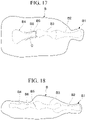
- a meat block B shown in Figs. 17 and 18 is processed.
- This meat block B is a pork shoulder meat block in which shoulder loin and spare ribs are removed from a half-back block of a pork carcass, has a wrist side B1 at one end, and includes a forearm bone B2, an humerus B3, and a scapula B4.
- the scapula B4 has a bulging bone head B5 at one end, the other end extends in a triangular shape, and a portion just below the bone head B5 is a constriction portion B6 with a narrow diameter.
- a bone removing device 1 of this embodiment is used to grip the constriction portion B6 as a part of the bone and peel that part off from the meat block B.
- the present invention is not limited to the pork shoulder meat and pork blocks and may be meat blocks of other animals.
- the bone is not limited to the scapula and the present invention can be applied to any other bone as well.
- a "part" of the bone to be gripped may be the constriction portion or the bone head and the present invention can be applied to one end or the center portion of the bone as well.
- Fig. 1 shows the bone removing device 1 according to an embodiment of the present invention and this bone removing device 1 has a rectangular parallelepiped frame 2 and a first conveyor 4, a second conveyor 6, and a third conveyor 8 arranged horizontally in a row, respectively.
- the first conveyor 4, the second conveyor 6, and the third conveyor 8 constitute a transfer mechanism.
- the first conveyor 4 is disposed outside the frame 2 and the second conveyor 6 and the third conveyor 8 are disposed inside the frame 2.
- the first conveyor 4, the second conveyor 6, and the third conveyor 8 can be individually operated and all meat blocks are conveyed from the upstream side (the right side in Fig. 1 ) to the downstream side (the left side in Fig. 1 ).
- a guide mechanism 10 is disposed above the second conveyor 6 and a grip mechanism 12 for gripping the scapula B4 is disposed above the third conveyor 8.
- a drive mechanism 16 for driving the grip mechanism 12 is disposed on the upper surface of the frame 2.
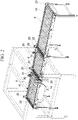
- Fig. 2 shows the first conveyor 4, the second conveyor 6, and the third conveyor 8 and all of these conveyors include a plurality of support plates 18 extending in a conveying direction and rollers 20 and 22.
- An endless roller belt (not shown) is wound on the rollers 20 and 22 so that the roller belt runs. The roller belt is periodically replaced and cleaned.
- a distance sensor 24 is installed at the end of the first conveyor 4, a distance sensor 26 is installed at the tip of the second conveyor 6, and a pair of passage sensors 28 is installed at the end of the second conveyor 6.
- a distance sensor 30 is installed at the tip of the third conveyor 8 and a distance sensor 32 is installed at the end thereof.
- the distance sensors measure the distance from the meat block B and detect that the meat block B has passed in a normal posture.
- the passage sensor 28 detects the passage of the meat block B regardless of the posture of the meat block B.
- These sensors are connected to a control panel (not shown) and their signals are used for the operation control described later.
- a guide 14 is fixed to the side surface of the third conveyor 8 to receive the scapula B4 removed from the meat block B and guide the scapula to a container (not shown).
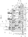
- Fig. 3 shows a relationship between the conveyors 4, 6, and 8, the guide mechanism 10, and the grip mechanism 12.
- First and second guide portions 34 and 36 having an elongated rail shape are disposed above the second conveyor 6 so that their longitudinal directions are parallel to the conveyor conveying direction.
- the first guide portion 34 is located lower than the second guide portion 36.
- the first guide portion 34 and the second guide portion 36 have substantially the same length, but a guide bar 35 is attached to the tip on the upstream side of the first guide portion 34.
- the guide bar 35 extends in the extension direction of the first guide portion 34 and the tip is rounded in a loop for safety.
- the guide bar 35 is guided to allow an operator to place the constriction portion B6 of the meat block B thereon so that the constriction portion B6 is smoothly introduced between the first guide portion 34 and the second guide portion 36.
- the gap between the first guide portion 34 and the second guide portion 36 is set to be slightly larger than the thickness of the constriction portion B6 and smaller than the diameter of the bone head B5 of the scapula B4. Accordingly, the constriction portion B6 is not pulled out and is smoothly guided over the entire length of the first guide portion 34 and the second guide portion 36.
- the lower ends of the first guide portion 34 and the second guide portion 36 are rounded not to damage the meat.
- a lower end 34A of the first guide portion 34 is inclined to be lowered as it goes toward the second guide portion 36 and supports a lower surface of the constriction portion B6.
- An upper end of the first guide portion 34 erects perpendicularly and a horizontal rotation shaft 46 is attached to a front surface thereof to be rotatable around the axis.
- the second guide portion 36 is attached to the rotation shaft 46 through a plurality of arms 53 and the second guide portion 36 is opened and closed with respect to the first guide portion 34 when the rotation shaft 46 rotates.
- the arm 53 has a function of finely adjusting the height and angle of the second guide portion 36.
- a handle 48 is fixed to an end of the rotation shaft 46 through a lever 50 and when the operator moves the handle 48, the second guide portion 36 moves to a jumping-up position and can be fixed at the jumping-up position as shown in Fig. 9 . Even when the second guide portion 36 jumps up in this way, there is an advantage that the guide mechanism 10 can be easily washed.
- the upper end of the first guide portion 34 is fixed to a lifting plate 38 disposed perpendicularly and the lifting plate 38 is supported to be elevatable through a pair of linear guides 44 attached to the frame 2.
- a horizontal plate 45 is fixed onto the frame 2, a lifting unit 40 is provided thereon, and the lifting plate 38 can be elevated to an arbitrary position by a servo motor 42.
- the servo motor 42 is connected to a switch and a control panel (not shown) and can adjust the height positions of the first guide portion 34 and the second guide portion 36 in accordance with the shape or size of the meat block B in such a manner that the operator manipulates the switch or operates the servo motor 42 using the control panel.
- the grip mechanism 12 includes a first grip portion 54 and a second grip portion 56 which are disposed on the downstream side of the first guide portion 34 and the second guide portion 36 and an open-and-close actuator 64 which opens and closes a gap between the first grip portion 54 and the second grip portion 56.
- the longitudinal directions of the first grip portion 54 and the second grip portion 56 are substantially aligned to the longitudinal directions of the first guide portion 34 and the second guide portion 36 and the constriction portion B6 guided by the first guide portion 34 and the second guide portion 36 is smoothly received in the gap between the first grip portion 54 and the second grip portion 56.
- the cross-sections of the lower ends of the first grip portion 54 and the second grip portion 56 are rounded not to damage the meat.
- a lower end 54A of the first grip portion 54 is inclined downward as it goes toward the second grip portion 56 and supports the lower surface of the constriction portion B6.
- An upper end of the first grip portion 54 erects perpendicularly and is fixed to a lifting plate 66 extending perpendicularly.
- the lifting plate 66 is attached to the frame 2 through a pair of linear guides 70 to be elevatable.
- a horizontal rotation shaft 60 is attached to an entire surface of a lower end of the lifting plate 66 to be rotatable around the axis.
- the second grip portion 56 is attached to both ends of the rotation shaft 60 through a pair of arms 62 and the second grip portion 56 is opened and closed with respect to the first grip portion 54 when the rotation shaft 60 rotates.
- the arm 62 has a function of finely adjusting the height and angle of the second grip portion 56.
- a shaft of the open-and-close actuator 64 is eccentrically connected to the center of the rotation shaft 60 and the main body of the open-and-close actuator 64 is fixed to the lifting plate 66.
- the rotation shaft 60 rotates so that the second grip portion 56 is opened and closed with respect to the first grip portion 54.
- the constriction portion B6 is elastically sandwiched and fixed between the second grip portion 56 and the first grip portion 54 with a constant force.
- the open-and-close actuator 64 is connected to a control panel (not shown).
- a horizontal frame 71 is fixed to an upper surface of the frame 2
- a slide stand 72 is horizontally disposed on the horizontal frame 71 through a linear guide 74, and the slide stand 72 is movable in the width direction of the third conveyor 8.
- a vertical actuator 68 including a servo motor 69 is attached onto the slide stand 72 and the shaft is connected to the lifting plate 66.
- a shaft of a horizontal actuator 76 including a servo motor 77 is connected to the slide stand 72 and the horizontal actuator 76 is fixed to the horizontal frame 71.
- the vertical actuator 68 and the horizontal actuator 76 are respectively connected to the control panel and the movement locus of the grip mechanism 12 in the virtual plane orthogonal to the conveying direction of the conveyor and the speed at each point can be programmed in advance by controlling the moving speed of each of the vertical actuator 68 and the horizontal actuator 76.
- a long and thin plate-shaped pressing body 58 is disposed on a lower surface of the lower end 54A of the first grip portion 54.
- the pressing body 58 has a shape extending substantially in parallel to the lower surface of the lower end 54A and has a length extending to the upstream side and the downstream side from the first grip portion 54 and the second grip portion 56.
- an upstream end of the pressing body 58 extends to below a downstream end of the first guide portion 34.
- Each of both ends of the pressing body 58 is connected to a lower end of the lifting body 78 and the lifting body 78 is supported by a pair of linear guides 80 fixed to the frame 2 to be elevatable.
- a shaft of a pressing mechanism 82 driven by a servo motor 84 is connected to the lifting body 78 and the pressing mechanism 82 is fixed onto the frame 2.
- the servo motor 84 When the servo motor 84 is operated, the pressing body 58 can be elevated from a position contacting the lower surface of the lower end 54A of the first grip portion 54 to a position in which the meat block B disposed on the third conveyor 8 is pressed against the third conveyor 8.
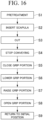
- step S1 to step S9 for each meat block B according to the flowchart of Fig. 16 , the following operation is programmed in advance in the above-described control panel (not shown), and the bone removing device 1 automatically performs step S3 to step S9 except for step S1 and step S2.
- step S3 to step S9 except for step S1 and step S2.
- step S1 the operator performs pretreatment for introducing the meat block B into the bone removing device 1.
- a pork shoulder meat block in which shoulder loin and spare ribs are removed from a half-back block of a pork carcass is carried as a material.
- the operator cuts the circumference C of the bone head B5 and the constriction portion B6 of the meat block B with a knife and lightly lifts the bone head B5 and the constriction portion B6 to be exposed from the meat block B. This operation can be done with a light force and does not require skill.
- the pretreated meat block B is sequentially placed on the first conveyor 4 while the wrist side B1 faces the rear side of the bone removing device 1.
- the meat block B is carried downstream by the first conveyor 4.
- step S2 the operator grips the meat block B carried to the downstream side of the first conveyor 4 and places the constriction portion B6 exposed from the meat block B by the pretreatment on the horizontal guide bar 35. Then, as the meat block B is carried to the downstream side, as shown in Fig. 10 , the constriction portion B6 slides into the gap between the first guide portion 34 and the second guide portion 36. At this time, the distance sensor 24 and the distance sensor 26 confirm whether the meat block B is guided in a normal posture. When an abnormal posture in which the meat block B is obliquely inclined with respect to the conveying direction is detected, the first conveyor 4 is stopped.
- step S3 when the distance sensor 24 confirms that the meat block B is carried in a normal posture, the second conveyor 6 is operated and the meat block B is conveyed to the downstream side at a conveying speed faster than that of the first conveyor 4 to be separated from the next meat block B.
- each constriction portion B6 can be reliably gripped by the first grip portion 54 and the second grip portion 56 by increasing the distance between the meat blocks B.
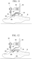
- step S4 when the passage sensor 28 confirms that the meat block B has passed, the third conveyor 8 is operated. Then, the constriction portion B6 moving along the first guide portion 34 and the second guide portion 36 slides into the gap between the first grip portion 54 and the second grip portion 56 and the constriction portion B6 moves to the downstream side while being guided by the first grip portion 54 and the second grip portion 56 as shown in Fig. 11 .
- the distance sensor 30 confirms whether the meat block B has passed in a normal posture. When an abnormal posture in which the meat block B is obliquely inclined with respect to the conveying direction is detected, the third conveyor 8 is stopped. When there is no abnormality, the meat block B is moved to the center of the longitudinal direction of the first grip portion 54 and the third conveyor 8 is stopped at that position.
- step S5 the open-and-close actuator 64 is operated so that the second grip portion 56 approaches the first grip portion 54 and the constriction portion B6 is reliably gripped and fixed by the first grip portion 54 and the second grip portion 56.
- step S6 as shown in Fig. 12 , the servo motor 84 is operated so that the lifting body 78 falls, the pressing body 58 is lowered, particularly the bone head B7 of the humerus B3 is pressed by the pressing body 58, and the meat block B is pressed and fixed to the third conveyor 8. Since the pressing body 58 is pressed against the bone head B7, the meat block B can be effectively fixed without the pressing body 58 striking into the meat.
- step S7 as shown in Fig. 13 , the vertical actuator 68 and the horizontal actuator 76 are operated so that the grip mechanism 12 is raised upward and is moved in a direction orthogonal to the conveyor conveying direction. Accordingly, the scapula B4 is peeled off from the meat block B and is lifted.
- the grip mechanism 12 is moved in the moving direction and at the moving speed in which the movements of the vertical actuator 68 and the horizontal actuator 76 are combined as shown in Fig. 15 .
- an efficient bone peeling operation according to the combination characteristics of the scapula B4 and the meat block B can be performed by setting each operation of the vertical actuator 68 and the horizontal actuator 76 to an optimal condition in advance. As a result, stable processing can be performed without damaging the meat by peeling the meat in an unreasonable direction or breaking the bones during peeling.
- Fig. 15 is a graph showing operation conditions of the vertical actuator 68 and the horizontal actuator 76 in an example in which good peeling results are obtained in the test for various conditions by the present inventors.
- the present invention is not limited to this condition.
- step S8 as shown in Fig. 14 , the open-and-close actuator 64 is operated to open the first grip portion 54 and the second grip portion 56 at a time point in which the scapula B4 suspended by the grip mechanism 12 reaches above the guide 14. Then, since the constriction portion B6 is released, the scapula B4 falls into the guide 14 (see Fig. 1 ) and is collected in a collection container (not shown).
- step S9 all of the pressing mechanism 82, the vertical actuator 68, and the horizontal actuator 76 are returned to the initial positions and the first grip portion 54 and the second grip portion 56 are returned to the original positions.
- the pressing body 58 is lifted up o release the meat block B and the third conveyor 8 is operated to carry the meat block B to the next step. Then, one cycle ends.
- the bone removing device since the constriction portion B6 of the bone in the meat block B is stably introduced into the gap between the first grip portion 54 and the second grip portion 56 in such a manner that the meat block B is placed and conveyed on the transfer mechanism (the first conveyor 4, the second conveyor 6, and the third conveyor 8), the bone removing operation can be stably performed even when the shape, size, and smoothness of the meat block B are different.
- the constriction portion B6 is highly reliably and stably introduced into the gap between the first grip portion 54 and the second grip portion 56 by the guidance of the first guide portion 34 and the second guide portion 36, the bone removing operation can be more stably performed even when the shape and size of the meat block B and the softness of the muscles of the meat and bone are different.
- the operation of the grip mechanism 12 is a moving direction, a moving speed, and a driving torque which are a combination of the ascent by the vertical actuator 68 and the horizontal movement in the conveyor width direction by the horizontal actuator 76, an efficient bone peeling operation according to the combination characteristics of the scapula B4 and the meat block B can be performed. As a result, stable processing can be performed without damaging the meat or breaking the bones during peeling.
- the control panel may include an input unit for inputting the shape or size of the meat block and may change the movement locus of the grip mechanism 12 in the virtual plane in response to the signal from the input unit.
- the signal from the input unit may be an output from a sensor that measures the shape or size of the meat block conveyed by the conveyor or a signal selected by a switch or the like switched by the determination of the operator.
- the meat block B is pressed by the pressing body 58 when the scapula B4 is peeled off by the grip mechanism 12, the meat block B does not lift or change its posture when the scapula B4 is peeled off. As a result, there is an advantage that a stable peeling operation can be performed. Further, since the bone head B7 is pressed by the pressing body 58, an effective pressing operation can be performed.
- the heights of the first guide portion 34 and the first guide portion 34 can be adjusted by the lifting unit 40 and the heights of the first grip portion 54 and the second grip portion 56 can be adjusted by the vertical actuator 68. Accordingly, a stable bone removing operation can be performed even when the shape or size of the meat block is different in a wide range.
- the constriction portion B6 is placed on the guide bar 35 and the constriction portion B6 is smoothly guided between the first guide portion 34 and the second guide portion 36, the bone removing operation can be more smoothly performed and the burden on the operator is small.
- the conveying timing of the meat block B can be adjusted by the first conveyor 4
- the delivery timing from the guide mechanism 10 to the grip mechanism 12 can be adjusted by the second conveyor 6, and the position and timing of the peeling operation can be adjusted by the third conveyor 8, it is easy to harmonize each operation at the optimum timing.
- the adjustment mechanism of the arm 53 and/or the adjustment mechanism of the arm 62 is adjusted to adjust the gap between the first guide portion 34 and the second guide portion 36 and/or the gap between the first grip portion 54 and the second grip portion 56. Accordingly, even when the shape or size of the meat block is different in a wider range, a stable bone removing operation can be performed.
- the gap between the first guide portion 34 and the second guide portion 36 can be widened by turning the second guide portion 36 around the rotation shaft 46 in accordance with the operation of the handle 48 and the maintenance can be easily performed.
- the present invention is applicable to the industries.
Landscapes
- Life Sciences & Earth Sciences (AREA)
- Engineering & Computer Science (AREA)
- Wood Science & Technology (AREA)
- Zoology (AREA)
- Food Science & Technology (AREA)
- Processing Of Meat And Fish (AREA)
Abstract
Description
- The present invention relates to a bone removing device and a bone removing method of removing a bone to be removed such as a scapula from a meat block such as a pork block.
- Since the operation of removing a bone to be removed, such as a scapula, from a meat block such as a pork block requires skill and is hard operation, automation is required.
-
Patent Literature 1 shows an example of a conventional bone removing device and, in this bone removing device, a constriction portion of a scapula is gripped by a portal chuck and the scapula is peeled off while a pork block is suspended and conveyed by a clamper. - [Patent Literature 1]
Japanese Patent No. 4327099 - In order to realize the device of
Patent Literature 1, it was necessary to perform operations of photographing a pork block suspended from a clamper by X-ray, measuring a position of a bone in the pork block in an image analysis, bending the pork block in accordance with the position of the bone, gripping a scapula using a hand tool attached to a tip of a robot, and peeling off the scapula from the pork block. - As described above, in the device of
Patent Literature 1, since it is necessary to control the operation according to the shape of the pork block or the arrangement of the bones in the suspended state with a high degree of freedom of posture, the position of the bone needs to be measured by X-ray photographing. However, X-ray transmission may be insufficient and bone position measurement by image analysis may not be performed accurately depending on the thickness of meat of the pork block. - Further, when the shape or size of the pork block is different from the usual one or when it is a soft pork block having meat softer than the usual one, the pork block cannot be bent properly according to the position of the bone or the position of the scapula is displaced so that the robot's hand tool cannot accurately grip the scapula in some cases. In such a case, it takes time and effort for an operator to manually adjust each part of a machine so that the bone removing operation can be smoothly performed.
- An object of the present invention is to provide a bone removing device and a bone removing method capable of stably performing a bone removing operation even when the shape, size, and softness of a meat block are different.
-
- [1] An aspect of the present invention is a bone removing device for removing a bone (as a part of the bone to grip, for example, a bone having a constriction portion or a bone head, for example, a scapula) to be removed from a meat block (for example, a pork block such as a pork arm block) including: a transfer mechanism which transfers a meat block from an upstream side to a downstream side; a grip mechanism which includes first and second grip portions and an open-and-close actuator opening and closing a gap between the first and second grip portions and introduces a part of the bone in the meat block into the gap between the first and second grip portions; and a drive mechanism which moves the grip mechanism so that the bone partially gripped by the grip mechanism is peeled off from the meat block.
- In this bone removing device, the meat block is placed and conveyed on the transfer mechanism so that a part of the bone in the meat block is introduced into the gap between the first grip portion and the second grip portion. When the part of the bone enters into the gap between the first grip portion and the second grip portion, the drive mechanism moves the grip mechanism and peels off the bone from the meat block.
- Thus, according to this bone removing device, since the part of the bone is stably introduced into the gap between the first grip portion and the second grip portion in such a manner that the meat block is placed and conveyed on the transfer mechanism, a bone removing operation can be stably performed even when the shape, size, and softness of the meat block are different. The moving direction of the grip mechanism may be any direction if the bone can be peeled off from the meat block. For example, the moving direction may be a direction away from the transfer mechanism.
- [2] In the device of the above [1], the drive mechanism may include a pressing mechanism which includes a pressing body disposed closer to the transfer mechanism than the first grip portion and the second grip portion and a pressing actuator moving the pressing body toward the transfer mechanism and presses the meat block by the pressing body when peeling off the bone from the meat block.
- In this case, since the meat block is pressed against the transfer mechanism by the pressing body when the grip mechanism is moved by the drive mechanism so that the bone is peeled off from the meat block, the meat block does not lift when peeling off the bone. As a result, there is an advantage that a stable peeling operation can be performed. Further, since the pressing body presses the meat block against the transfer mechanism, the position or shape of the meat block can also be standardized. This point also contributes to the stabilization of processing. The pressing body may be used to press the bone head of the bone remaining in the meat block. In that case, since the hard bone head is pressed, the meat block can be effectively fixed.
- [3] The device of the above [1] or [2] may further include: a guide mechanism which includes first and second guide portions arranged along the transfer mechanism with a gap therebetween and guides a part of the bone in the meat block conveyed by the transfer mechanism to the gap between the first grip portion and the second grip portion through the gap.
- In this case, when the meat block is placed on the transfer mechanism and a part of the bone of the meat block is disposed through the gap between the first guide portion and the second guide portion, the meat block moves while the part of the bone is guided through the gap between the first guide portion and the second guide portion by the conveying operation using the transfer mechanism and the part is introduced into the gap between the first grip portion and the second grip portion.
- Thus, according to this bone removing device, since the part of the bone is stably introduced into the gap between the first grip portion and the second grip portion by the guidance of the first guide portion and the second guide portion, a bone removing operation can be more stably performed even when the shape, size, and softness of the meat block are different.
- [4] In the device of the above [1] to [3], the drive mechanism may include a vertical actuator which moves the grip mechanism in a direction perpendicular to a conveying surface of the transfer mechanism and a horizontal actuator which moves the grip mechanism in a width direction of the transfer mechanism.
- In this case, since the operation of the grip mechanism is a moving direction and a moving speed which is a combination of the ascent by the vertical actuator and the horizontal movement in the width direction of the transfer mechanism by the horizontal actuator, an efficient bone peeling operation according to the combination characteristics of the bone and the meat block can be performed. As a result, stable processing can be performed without damaging the meat by peeling the meat or breaking the bones during peeling.
- [5] In the device of the above [4], the drive mechanism may include a controller which programs a movement locus of the grip mechanism in a virtual plane orthogonal to a conveying direction of the transfer mechanism in advance by controlling a moving speed of each of the vertical actuator and the horizontal actuator.
- In this case, since the movement locus of the grip mechanism in the virtual plane and the speed at each position can be programmed in advance by the controller, an efficient bone removing process according to the characteristic of the meat block can be performed. The controller includes an input unit for inputting the shape or size of the meat block and may change the movement locus of the grip mechanism in the virtual plane orthogonal to the conveying direction of the transfer mechanism in response to the signal from the input unit. The signal from the input unit may be an output from a sensor that measures the shape or size of the meat block conveyed by the transfer mechanism or a signal selected by a switch or the like switched by the determination of the operator.
- [6] The device of the above [3] may further include: a guide position adjustment mechanism which adjusts a height of each of the first guide portion and the second guide portion from the transfer mechanism; and a grip position adjustment mechanism which adjusts a height of each of the first grip portion and the second grip portion from the transfer mechanism.
- In this case, for example, even when the shape or size of the meat block is different beyond the allowable range, the heights of the first guide portion and the second guide portion from the transfer mechanism can be adjusted by the guide position adjustment mechanism and the heights of the first grip portion and the second grip portion from the transfer mechanism can be adjusted by the grip position adjustment mechanism. Accordingly, a stable bone removing operation can be performed even when the shape or size of the meat block is different in a wider range.
- [7] In the device of the above [3] or [6], the first guide portion may be located at a position closer to the transfer mechanism than the second guide portion and an upstream end of the first guide portion may be provided with a guide bar extending toward an upstream side in relation to the second guide portion.
- In this case, when a part of the bone is placed on the guide bar, the part of the bone slides along the guide bar and is smoothly guided into the gap between the first guide portion and the second guide portion. Thus, there is an advantage that a bone removing operation can be more smoothly performed.
- [8] In the device of any one of the above [3], [6], and [7], the transfer mechanism may include a first conveyor, a second conveyor, and a third conveyor which are arranged from an upstream side toward a downstream side and are respectively independently operable, the first guide portion and the second guide portion may be arranged along the second conveyor, and the first grip portion and the second grip portion may be arranged along the third conveyor.
- In this case, since the conveying timing of the meat block is adjusted by the first conveyor, the delivery timing from the first guide portion and the second guide portion to the first grip portion and the second grip portion is adjusted by the second conveyor, and the position and timing of the peeling operation are adjusted by the third conveyor, it is easy to harmonize each operation at the optimum timing.
- [9] The device of any one of the above [3], [6], [7], and [8] may further include: a guide gap adjustment mechanism which adjusts a distance of a gap between the first guide portion and the second guide portion; and a grip gap adjustment mechanism which adjusts a distance of a gap between the first grip portion and the second grip portion.
- In this case, for example, even when the thickness or size of the bone of the meat block is different beyond the allowable range, the guide gap adjustment mechanism and/or the grip gap adjustment mechanism is operated to adjust the distance of the gap between the first guide portion and the second guide portion and/or the distance of the gap between the first grip portion and the second grip portion. Accordingly, even when the shape or size of the meat block is different in a wider range, a stable bone removing operation can be performed.
- [10] The device of any one of the above [3], [6], [7], [8], and [9] may further include: a second guide turning mechanism which includes a turning shaft disposed in parallel to the first guide portion and an arm supporting the second guide portion to be turned around the turning shaft.
- In this case, the gap between the first guide portion and the second guide portion can be widened by turning the second guide portion around the turning shaft using the second guide turning mechanism and the maintenance can be easily performed.
- [11] Another aspect of the present invention is a bone removing method of removing a bone to be removed from a meat block including: conveying a meat block from an upstream side to a downstream side by a transfer mechanism transferring the meat block; introducing a part of the bone in the meat block into a gap between a first grip portion and a second grip portion; and peeling off the bone from the meat block by moving the first grip portion and the second grip portion gripping the part of the bone in the gap.
- In this bone removing method, the meat block is placed and conveyed on the transfer mechanism and a part of the bone in the meat block is introduced into the gap between the first grip portion and the second grip portion. When the part of the bone enters the gap between the first grip portion and the second grip portion, the drive mechanism moves the grip mechanism in a direction away from the transfer mechanism and peels off the bone from the meat block.
- Thus, according to the bone removing method, since the part of the bone is stably introduced into the gap between the first grip portion and the second grip portion in such a manner that the meat block is placed and conveyed on the transfer mechanism, a bone removing operation can be stably performed even when the shape, size, and softness of the meat block are different.
- [12] The method of the above [10] further includes: guiding a part of the bone conveyed by the transfer mechanism to the gap between the first grip portion and the second grip portion through a gap between a first guide portion and a second guide portion disposed along the transfer mechanism.
- According to this method, since the part of the bone is stably introduced into the gap between the first grip portion and the second grip portion by the guidance of the first guide portion and the second guide portion, a bone removing operation can be stably performed even when the shape, size, and softness of the meat block are different.
- [13] In the device of the above [1] to [10] and the method of the above [10] to [13], the meat block may be a pork block of a pork shoulder meat, the bone may be a scapula, and the part of the bone may be a part just below the bone head of the scapula. However, the present invention is not limited to the pork shoulder meat and pork blocks and may be meat blocks of other animals. Further, the bone is not limited to the scapula and any bone having a part at the end can be similarly applied.
- Further, as in the embodiments described later, the configurations of the above-described devices [1] to [10] and methods [11] and [12] can be combined with each other.
- According to the bone removing device and the bone removing method of the present invention, since the part of the bone is stably introduced into the gap between the first grip portion and the second grip portion in such a manner that the meat block is placed and conveyed on the transfer mechanism, there is an excellent effect that a bone removing operation can be stably performed even when the shape, size, and softness of the meat block are different.
-
-
Fig. 1 is a perspective view of a bone removing device according to an embodiment of the present invention. -
Fig. 2 is a perspective view showing a conveyor (transfer mechanism) of the bone removing device. -
Fig. 3 is a front view showing a guide mechanism, a grip mechanism, and a drive mechanism of the bone removing device. -
Fig. 4 is a perspective view showing the guide mechanism of the bone removing device. -
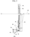
Fig. 5 is a side view showing the guide mechanism of the bone removing device. -
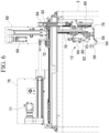
Fig. 6 is a side view showing the grip mechanism and the drive mechanism of the bone removing device. -
Fig. 7 is a perspective view showing the grip mechanism and the drive mechanism of the bone removing device. -
Fig. 8 is a perspective view showing the grip mechanism and the drive mechanism of the bone removing device. -
Fig. 9 is a side view showing a state in which the guide mechanism of the bone removing device is opened. -
Fig. 10 is a side view showing a state in which, for example, a constriction portion corresponding to a part of a bone is guided by the guide mechanism of the bone removing device. -
Fig. 11 is a side view showing a state in which the constriction portion is gripped by the grip mechanism of the bone removing device. -
Fig. 12 is a side view showing a state in which the constriction portion is gripped by the grip mechanism of the bone removing device and a meat block is pressed by a pressing body. -
Fig. 13 is a side view showing a state in which a scapula is peeled off by the grip mechanism of the bone removing device. -
Fig. 14 is a side view showing a state in which the scapula is released by the grip mechanism of the bone removing device. -
Fig. 15 is a graph showing an example of a movement locus of the grip mechanism when the bone removing device peels off the scapula. -
Fig. 16 is a flowchart showing an example of an operation of the bone removing device. -
Fig. 17 is a plan view showing an example of a meat block from which a bone is removed by the bone removing device. -
Fig. 18 is a side view showing an example of a meat block from which a bone is removed by the bone removing device. - Hereinafter, an embodiment of the present invention will be described with reference to the drawings. In this embodiment, for example, a meat block B shown in
Figs. 17 and 18 is processed. This meat block B is a pork shoulder meat block in which shoulder loin and spare ribs are removed from a half-back block of a pork carcass, has a wrist side B1 at one end, and includes a forearm bone B2, an humerus B3, and a scapula B4. The scapula B4 has a bulging bone head B5 at one end, the other end extends in a triangular shape, and a portion just below the bone head B5 is a constriction portion B6 with a narrow diameter. Abone removing device 1 of this embodiment is used to grip the constriction portion B6 as a part of the bone and peel that part off from the meat block B. As a pretreatment for thebone removing device 1, it is necessary to cut a circumference C of the bone head B5 and the constriction portion B6 with a knife to expose the bone head B5 and the constriction portion B6. However, the present invention is not limited to the pork shoulder meat and pork blocks and may be meat blocks of other animals. The bone is not limited to the scapula and the present invention can be applied to any other bone as well. A "part" of the bone to be gripped may be the constriction portion or the bone head and the present invention can be applied to one end or the center portion of the bone as well. -
Fig. 1 shows thebone removing device 1 according to an embodiment of the present invention and thisbone removing device 1 has arectangular parallelepiped frame 2 and afirst conveyor 4, asecond conveyor 6, and athird conveyor 8 arranged horizontally in a row, respectively. Thefirst conveyor 4, thesecond conveyor 6, and thethird conveyor 8 constitute a transfer mechanism. Thefirst conveyor 4 is disposed outside theframe 2 and thesecond conveyor 6 and thethird conveyor 8 are disposed inside theframe 2. Thefirst conveyor 4, thesecond conveyor 6, and thethird conveyor 8 can be individually operated and all meat blocks are conveyed from the upstream side (the right side inFig. 1 ) to the downstream side (the left side inFig. 1 ). Inside theframe 2, aguide mechanism 10 is disposed above thesecond conveyor 6 and agrip mechanism 12 for gripping the scapula B4 is disposed above thethird conveyor 8. Adrive mechanism 16 for driving thegrip mechanism 12 is disposed on the upper surface of theframe 2. Hereinafter, these configurations will be described in detail. -
Fig. 2 shows thefirst conveyor 4, thesecond conveyor 6, and thethird conveyor 8 and all of these conveyors include a plurality ofsupport plates 18 extending in a conveying direction androllers rollers - A
distance sensor 24 is installed at the end of thefirst conveyor 4, adistance sensor 26 is installed at the tip of thesecond conveyor 6, and a pair ofpassage sensors 28 is installed at the end of thesecond conveyor 6. Adistance sensor 30 is installed at the tip of thethird conveyor 8 and adistance sensor 32 is installed at the end thereof. When the meat block B passes immediately before thedistance sensors passage sensor 28 detects the passage of the meat block B regardless of the posture of the meat block B. These sensors are connected to a control panel (not shown) and their signals are used for the operation control described later. Aguide 14 is fixed to the side surface of thethird conveyor 8 to receive the scapula B4 removed from the meat block B and guide the scapula to a container (not shown). -
Fig. 3 shows a relationship between theconveyors guide mechanism 10, and thegrip mechanism 12. First andsecond guide portions second conveyor 6 so that their longitudinal directions are parallel to the conveyor conveying direction. Thefirst guide portion 34 is located lower than thesecond guide portion 36. Thefirst guide portion 34 and thesecond guide portion 36 have substantially the same length, but aguide bar 35 is attached to the tip on the upstream side of thefirst guide portion 34. Theguide bar 35 extends in the extension direction of thefirst guide portion 34 and the tip is rounded in a loop for safety. Theguide bar 35 is guided to allow an operator to place the constriction portion B6 of the meat block B thereon so that the constriction portion B6 is smoothly introduced between thefirst guide portion 34 and thesecond guide portion 36. - As shown in
Fig. 5 , there is a gap of almost the same distance over the entire length between alower end 34A of thefirst guide portion 34 and a lower end of thesecond guide portion 36 and the constriction portion B6 of the scapula B4 in the meat block B conveyed by thesecond conveyor 6 is sandwiched and guided through the gap. The gap between thefirst guide portion 34 and thesecond guide portion 36 is set to be slightly larger than the thickness of the constriction portion B6 and smaller than the diameter of the bone head B5 of the scapula B4. Accordingly, the constriction portion B6 is not pulled out and is smoothly guided over the entire length of thefirst guide portion 34 and thesecond guide portion 36. The lower ends of thefirst guide portion 34 and thesecond guide portion 36 are rounded not to damage the meat. - As shown in
Fig. 5 , alower end 34A of thefirst guide portion 34 is inclined to be lowered as it goes toward thesecond guide portion 36 and supports a lower surface of the constriction portion B6. An upper end of thefirst guide portion 34 erects perpendicularly and ahorizontal rotation shaft 46 is attached to a front surface thereof to be rotatable around the axis. Thesecond guide portion 36 is attached to therotation shaft 46 through a plurality ofarms 53 and thesecond guide portion 36 is opened and closed with respect to thefirst guide portion 34 when therotation shaft 46 rotates. Thearm 53 has a function of finely adjusting the height and angle of thesecond guide portion 36. - A
handle 48 is fixed to an end of therotation shaft 46 through alever 50 and when the operator moves thehandle 48, thesecond guide portion 36 moves to a jumping-up position and can be fixed at the jumping-up position as shown inFig. 9 . Even when thesecond guide portion 36 jumps up in this way, there is an advantage that theguide mechanism 10 can be easily washed. - As shown in
Fig. 4 , the upper end of thefirst guide portion 34 is fixed to a liftingplate 38 disposed perpendicularly and the liftingplate 38 is supported to be elevatable through a pair oflinear guides 44 attached to theframe 2. Ahorizontal plate 45 is fixed onto theframe 2, a liftingunit 40 is provided thereon, and the liftingplate 38 can be elevated to an arbitrary position by aservo motor 42. Theservo motor 42 is connected to a switch and a control panel (not shown) and can adjust the height positions of thefirst guide portion 34 and thesecond guide portion 36 in accordance with the shape or size of the meat block B in such a manner that the operator manipulates the switch or operates theservo motor 42 using the control panel. - As shown in
Fig. 3 , thegrip mechanism 12 includes afirst grip portion 54 and asecond grip portion 56 which are disposed on the downstream side of thefirst guide portion 34 and thesecond guide portion 36 and an open-and-close actuator 64 which opens and closes a gap between thefirst grip portion 54 and thesecond grip portion 56. The longitudinal directions of thefirst grip portion 54 and thesecond grip portion 56 are substantially aligned to the longitudinal directions of thefirst guide portion 34 and thesecond guide portion 36 and the constriction portion B6 guided by thefirst guide portion 34 and thesecond guide portion 36 is smoothly received in the gap between thefirst grip portion 54 and thesecond grip portion 56. The cross-sections of the lower ends of thefirst grip portion 54 and thesecond grip portion 56 are rounded not to damage the meat. - As shown in
Fig. 6 , a lower end 54A of thefirst grip portion 54 is inclined downward as it goes toward thesecond grip portion 56 and supports the lower surface of the constriction portion B6. An upper end of thefirst grip portion 54 erects perpendicularly and is fixed to a liftingplate 66 extending perpendicularly. The liftingplate 66 is attached to theframe 2 through a pair oflinear guides 70 to be elevatable. - As shown in
Fig. 8 , ahorizontal rotation shaft 60 is attached to an entire surface of a lower end of the liftingplate 66 to be rotatable around the axis. Thesecond grip portion 56 is attached to both ends of therotation shaft 60 through a pair ofarms 62 and thesecond grip portion 56 is opened and closed with respect to thefirst grip portion 54 when therotation shaft 60 rotates. Thearm 62 has a function of finely adjusting the height and angle of thesecond grip portion 56. A shaft of the open-and-close actuator 64 is eccentrically connected to the center of therotation shaft 60 and the main body of the open-and-close actuator 64 is fixed to the liftingplate 66. When the open-and-close actuator 64 is operated, therotation shaft 60 rotates so that thesecond grip portion 56 is opened and closed with respect to thefirst grip portion 54. At the closed position of thesecond grip portion 56, the constriction portion B6 is elastically sandwiched and fixed between thesecond grip portion 56 and thefirst grip portion 54 with a constant force. The open-and-close actuator 64 is connected to a control panel (not shown). - As shown in
Fig. 3 , ahorizontal frame 71 is fixed to an upper surface of theframe 2, aslide stand 72 is horizontally disposed on thehorizontal frame 71 through alinear guide 74, and the slide stand 72 is movable in the width direction of thethird conveyor 8. Avertical actuator 68 including aservo motor 69 is attached onto theslide stand 72 and the shaft is connected to the liftingplate 66. - As shown in
Fig. 7 , a shaft of ahorizontal actuator 76 including aservo motor 77 is connected to theslide stand 72 and thehorizontal actuator 76 is fixed to thehorizontal frame 71. Thevertical actuator 68 and thehorizontal actuator 76 are respectively connected to the control panel and the movement locus of thegrip mechanism 12 in the virtual plane orthogonal to the conveying direction of the conveyor and the speed at each point can be programmed in advance by controlling the moving speed of each of thevertical actuator 68 and thehorizontal actuator 76. - As shown in
Fig. 8 , a long and thin plate-shapedpressing body 58 is disposed on a lower surface of the lower end 54A of thefirst grip portion 54. Thepressing body 58 has a shape extending substantially in parallel to the lower surface of the lower end 54A and has a length extending to the upstream side and the downstream side from thefirst grip portion 54 and thesecond grip portion 56. As shown inFig. 3 , an upstream end of thepressing body 58 extends to below a downstream end of thefirst guide portion 34. - Each of both ends of the
pressing body 58 is connected to a lower end of the liftingbody 78 and the liftingbody 78 is supported by a pair oflinear guides 80 fixed to theframe 2 to be elevatable. A shaft of apressing mechanism 82 driven by aservo motor 84 is connected to the liftingbody 78 and thepressing mechanism 82 is fixed onto theframe 2. When theservo motor 84 is operated, thepressing body 58 can be elevated from a position contacting the lower surface of the lower end 54A of thefirst grip portion 54 to a position in which the meat block B disposed on thethird conveyor 8 is pressed against thethird conveyor 8. - Next, a bone removing method using the
bone removing device 1 will be described. This method is to repeat step S1 to step S9 for each meat block B according to the flowchart ofFig. 16 , the following operation is programmed in advance in the above-described control panel (not shown), and thebone removing device 1 automatically performs step S3 to step S9 except for step S1 and step S2. Hereinafter, each step will be described sequentially. - In step S1, the operator performs pretreatment for introducing the meat block B into the
bone removing device 1. As shown inFigs. 17 and 18 , a pork shoulder meat block in which shoulder loin and spare ribs are removed from a half-back block of a pork carcass is carried as a material. The operator cuts the circumference C of the bone head B5 and the constriction portion B6 of the meat block B with a knife and lightly lifts the bone head B5 and the constriction portion B6 to be exposed from the meat block B. This operation can be done with a light force and does not require skill. The pretreated meat block B is sequentially placed on thefirst conveyor 4 while the wrist side B1 faces the rear side of thebone removing device 1. The meat block B is carried downstream by thefirst conveyor 4. - In step S2, the operator grips the meat block B carried to the downstream side of the
first conveyor 4 and places the constriction portion B6 exposed from the meat block B by the pretreatment on thehorizontal guide bar 35. Then, as the meat block B is carried to the downstream side, as shown inFig. 10 , the constriction portion B6 slides into the gap between thefirst guide portion 34 and thesecond guide portion 36. At this time, thedistance sensor 24 and thedistance sensor 26 confirm whether the meat block B is guided in a normal posture. When an abnormal posture in which the meat block B is obliquely inclined with respect to the conveying direction is detected, thefirst conveyor 4 is stopped. - In step S3, when the
distance sensor 24 confirms that the meat block B is carried in a normal posture, thesecond conveyor 6 is operated and the meat block B is conveyed to the downstream side at a conveying speed faster than that of thefirst conveyor 4 to be separated from the next meat block B. Here, each constriction portion B6 can be reliably gripped by thefirst grip portion 54 and thesecond grip portion 56 by increasing the distance between the meat blocks B. - In step S4, when the
passage sensor 28 confirms that the meat block B has passed, thethird conveyor 8 is operated. Then, the constriction portion B6 moving along thefirst guide portion 34 and thesecond guide portion 36 slides into the gap between thefirst grip portion 54 and thesecond grip portion 56 and the constriction portion B6 moves to the downstream side while being guided by thefirst grip portion 54 and thesecond grip portion 56 as shown inFig. 11 . Thedistance sensor 30 confirms whether the meat block B has passed in a normal posture. When an abnormal posture in which the meat block B is obliquely inclined with respect to the conveying direction is detected, thethird conveyor 8 is stopped. When there is no abnormality, the meat block B is moved to the center of the longitudinal direction of thefirst grip portion 54 and thethird conveyor 8 is stopped at that position. - In step S5, the open-and-
close actuator 64 is operated so that thesecond grip portion 56 approaches thefirst grip portion 54 and the constriction portion B6 is reliably gripped and fixed by thefirst grip portion 54 and thesecond grip portion 56. - In step S6, as shown in
Fig. 12 , theservo motor 84 is operated so that the liftingbody 78 falls, thepressing body 58 is lowered, particularly the bone head B7 of the humerus B3 is pressed by thepressing body 58, and the meat block B is pressed and fixed to thethird conveyor 8. Since thepressing body 58 is pressed against the bone head B7, the meat block B can be effectively fixed without thepressing body 58 striking into the meat. - In step S7, as shown in
Fig. 13 , thevertical actuator 68 and thehorizontal actuator 76 are operated so that thegrip mechanism 12 is raised upward and is moved in a direction orthogonal to the conveyor conveying direction. Accordingly, the scapula B4 is peeled off from the meat block B and is lifted. At this time, since thegrip mechanism 12 is moved in the moving direction and at the moving speed in which the movements of thevertical actuator 68 and thehorizontal actuator 76 are combined as shown inFig. 15 , an efficient bone peeling operation according to the combination characteristics of the scapula B4 and the meat block B can be performed by setting each operation of thevertical actuator 68 and thehorizontal actuator 76 to an optimal condition in advance. As a result, stable processing can be performed without damaging the meat by peeling the meat in an unreasonable direction or breaking the bones during peeling. -
Fig. 15 is a graph showing operation conditions of thevertical actuator 68 and thehorizontal actuator 76 in an example in which good peeling results are obtained in the test for various conditions by the present inventors. However, the present invention is not limited to this condition. - In step S8, as shown in
Fig. 14 , the open-and-close actuator 64 is operated to open thefirst grip portion 54 and thesecond grip portion 56 at a time point in which the scapula B4 suspended by thegrip mechanism 12 reaches above theguide 14. Then, since the constriction portion B6 is released, the scapula B4 falls into the guide 14 (seeFig. 1 ) and is collected in a collection container (not shown). - In step S9, all of the
pressing mechanism 82, thevertical actuator 68, and thehorizontal actuator 76 are returned to the initial positions and thefirst grip portion 54 and thesecond grip portion 56 are returned to the original positions. Thepressing body 58 is lifted up o release the meat block B and thethird conveyor 8 is operated to carry the meat block B to the next step. Then, one cycle ends. - As described above, according to this bone removing device, since the constriction portion B6 of the bone in the meat block B is stably introduced into the gap between the
first grip portion 54 and thesecond grip portion 56 in such a manner that the meat block B is placed and conveyed on the transfer mechanism (thefirst conveyor 4, thesecond conveyor 6, and the third conveyor 8), the bone removing operation can be stably performed even when the shape, size, and smoothness of the meat block B are different. - Further, since the constriction portion B6 is highly reliably and stably introduced into the gap between the
first grip portion 54 and thesecond grip portion 56 by the guidance of thefirst guide portion 34 and thesecond guide portion 36, the bone removing operation can be more stably performed even when the shape and size of the meat block B and the softness of the muscles of the meat and bone are different. - Further, since the operation of the
grip mechanism 12 is a moving direction, a moving speed, and a driving torque which are a combination of the ascent by thevertical actuator 68 and the horizontal movement in the conveyor width direction by thehorizontal actuator 76, an efficient bone peeling operation according to the combination characteristics of the scapula B4 and the meat block B can be performed. As a result, stable processing can be performed without damaging the meat or breaking the bones during peeling. - Further, since the movement locus of the
grip mechanism 12 in the virtual plane and the speed at each position can be programmed in advance by the control panel (controller), an efficient bone removing process can be performed according to the characteristics of the meat block. The control panel may include an input unit for inputting the shape or size of the meat block and may change the movement locus of thegrip mechanism 12 in the virtual plane in response to the signal from the input unit. The signal from the input unit may be an output from a sensor that measures the shape or size of the meat block conveyed by the conveyor or a signal selected by a switch or the like switched by the determination of the operator. - Further, since the meat block B is pressed by the
pressing body 58 when the scapula B4 is peeled off by thegrip mechanism 12, the meat block B does not lift or change its posture when the scapula B4 is peeled off. As a result, there is an advantage that a stable peeling operation can be performed. Further, since the bone head B7 is pressed by thepressing body 58, an effective pressing operation can be performed. - Further, for example, even when the shape or size of the meat block is different beyond the allowable range, the heights of the
first guide portion 34 and thefirst guide portion 34 can be adjusted by the liftingunit 40 and the heights of thefirst grip portion 54 and thesecond grip portion 56 can be adjusted by thevertical actuator 68. Accordingly, a stable bone removing operation can be performed even when the shape or size of the meat block is different in a wide range. - Further, since the constriction portion B6 is placed on the
guide bar 35 and the constriction portion B6 is smoothly guided between thefirst guide portion 34 and thesecond guide portion 36, the bone removing operation can be more smoothly performed and the burden on the operator is small. - Further, since the conveying timing of the meat block B can be adjusted by the
first conveyor 4, the delivery timing from theguide mechanism 10 to thegrip mechanism 12 can be adjusted by thesecond conveyor 6, and the position and timing of the peeling operation can be adjusted by thethird conveyor 8, it is easy to harmonize each operation at the optimum timing. - Further, for example, even when the thickness or size of the bone of the meat block is different beyond the allowable range, the adjustment mechanism of the
arm 53 and/or the adjustment mechanism of thearm 62 is adjusted to adjust the gap between thefirst guide portion 34 and thesecond guide portion 36 and/or the gap between thefirst grip portion 54 and thesecond grip portion 56. Accordingly, even when the shape or size of the meat block is different in a wider range, a stable bone removing operation can be performed. - Further, the gap between the
first guide portion 34 and thesecond guide portion 36 can be widened by turning thesecond guide portion 36 around therotation shaft 46 in accordance with the operation of thehandle 48 and the maintenance can be easily performed. - According to the bone removing device and the bone removing method of the present invention, since there is an excellent effect that the bone removing operation can be stably performed even when the shape, size, and softness of the meat block are different, the present invention is applicable to the industries.
-
- 1: Bone removing device
- 2: Frame
- 4: First conveyor (part of transfer mechanism)
- 6: Second conveyor (part of transfer mechanism)
- 8: Third conveyor (part of transfer mechanism)
- 10: Guide mechanism
- 12: Grip mechanism
- 14: Guide
- 16: Drive mechanism
- 18: Support plate
- 2: Frame
- 20: Roller
- 22: Roller
- 24: Distance sensor
- 26: Distance sensor
- 28: Passage sensor
- 30: Distance sensor
- 32: Distance sensor
- 34: First guide portion
- 34A: Lower end
- 35: Guide bar
- 36: Second guide portion
- 38: Lifting plate
- 4: First conveyor
- 40: Lifting unit
- 42: Servo motor
- 44: Linear guide
- 45: Horizontal plate
- 46: Rotation shaft
- 48: Handle
- 50: Lever
- 52: Connection portion
- 53: Arm
- 54: First grip portion
- 54A: Lower end
- 56: Second grip portion
- 58: Pressing body
- 6: Second conveyor
- 60: Rotation shaft
- 62: Arm
- 64: Open-and-close actuator
- 66: Lifting plate
- 68: Vertical actuator
- 69: Servo motor
- 70: Linear guide
- 71: Horizontal frame
- 72: Slide stand
- 74: Linear guide
- 76: Horizontal actuator
- 77: Servo motor
- 78: Lifting body
- 8: Third conveyor
- 80: Linear guide
- 82: Pressing mechanism
- 84: Servo motor
- B: Meat block
- B1: Wrist side
- B2: Forearm bone
- B3: Humerus
- B4: Scapula
- B5: Bone head
- B6: Constriction portion (portion to be gripped)
- B7: Bone head
Claims (13)
- A bone removing device for removing a bone to be removed from a meat block, comprising:a transfer mechanism which transfers a meat block from an upstream side to a downstream side;a grip mechanism which includes first and second grip portions and an open-and-close actuator opening and closing a gap between the first and second grip portions and introduces a part of the bone in the meat block into the gap between the first and second grip portions; anda drive mechanism which moves the grip mechanism so that the bone partially gripped by the grip mechanism is peeled off from the meat block.
- The bone removing device according to claim 1,
wherein the drive mechanism includes a pressing mechanism which includes a pressing body disposed closer to the transfer mechanism than the first grip portion and the second grip portion and a pressing actuator moving the pressing body toward the transfer mechanism and presses the meat block by the pressing body when peeling off the bone from the meat block. - The bone removing device according to claim 1 or 2, further comprising:
a guide mechanism which includes first and second guide portions arranged along the transfer mechanism with a gap therebetween and guides a part of the bone in the meat block conveyed by the transfer mechanism to a gap between the first grip portion and the second grip portion through the gap. - The bone removing device according to any one of claims 1 to 3,
wherein the drive mechanism includes a vertical actuator which moves the grip mechanism in a direction perpendicular to a conveying surface of the transfer mechanism and a horizontal actuator which moves the grip mechanism in a width direction of the transfer mechanism. - The bone removing device according to claim 4,
wherein the drive mechanism includes a controller which programs a movement locus of the grip mechanism in a virtual plane orthogonal to a conveying direction of the transfer mechanism in advance by controlling a moving speed of each of the vertical actuator and the horizontal actuator. - The bone removing device according to claim 3, further comprising:a guide position adjustment mechanism which adjusts a height of each of the first guide portion and the second guide portion from the transfer mechanism; anda grip position adjustment mechanism which adjusts a height of each of the first grip portion and the second grip portion from the transfer mechanism.
- The bone removing device according to claim 3 or 6,
wherein the first guide portion is located at a position closer to the transfer mechanism than the second guide portion and an upstream end of the first guide portion is provided with a guide bar extending toward an upstream side in relation to the second guide portion. - The bone removing device according to any one of claims 3, 6 and 7,wherein the transfer mechanism includes a first conveyor, a second conveyor, and a third conveyor which are arranged from an upstream side toward a downstream side and are respectively independently operable,wherein the first guide portion and the second guide portion are arranged along the second conveyor, andwherein the first grip portion and the second grip portion are arranged along the third conveyor.
- The bone removing device according to any one of claims 3, 6, 7 and 8, further comprising:a guide gap adjustment mechanism which adjusts a distance of a gap between the first guide portion and the second guide portion; anda grip gap adjustment mechanism which adjusts a distance of a gap between the first grip portion and the second grip portion.
- The bone removing device according to any one of claims 3, 6, 7, 8 and 9, further comprising:
a second guide turning mechanism which includes a turning shaft disposed in parallel to the first guide portion and an arm supporting the second guide portion to be turned around the turning shaft. - A bone removing method of removing a bone to be removed from a meat block, comprising:conveying the meat block from an upstream side to a downstream side by a transfer mechanism transferring the meat block;introducing a part of the bone in the meat block into a gap between a first grip portion and a second grip portion; andpeeling off the bone from the meat block by moving the first grip portion and the second grip portion gripping the part of the bone in the gap.
- The bone removing method according to claim 11, further comprising:
guiding a part of the bone conveyed by the transfer mechanism to the gap between the first grip portion and the second grip portion through a gap between a first guide portion and a second guide portion disposed along the transfer mechanism. - The bone removing method according to claim 11 or 12,
wherein the meat block is a pork shoulder meat, the bone is a scapula, and the part of the bone is a bone head of the scapula or a part just below the bone head.
Applications Claiming Priority (1)
| Application Number | Priority Date | Filing Date | Title |
|---|---|---|---|
| PCT/JP2020/014511 WO2021199140A1 (en) | 2020-03-30 | 2020-03-30 | Bone removal device and bone removal method |
Publications (4)
| Publication Number | Publication Date |
|---|---|
| EP4129070A1 true EP4129070A1 (en) | 2023-02-08 |
| EP4129070A4 EP4129070A4 (en) | 2023-12-06 |
| EP4129070C0 EP4129070C0 (en) | 2025-04-30 |
| EP4129070B1 EP4129070B1 (en) | 2025-04-30 |
Family
ID=77927993
Family Applications (1)
| Application Number | Title | Priority Date | Filing Date |
|---|---|---|---|
| EP20894947.9A Active EP4129070B1 (en) | 2020-03-30 | 2020-03-30 | Bone removal device and bone removal method |
Country Status (3)
| Country | Link |
|---|---|
| EP (1) | EP4129070B1 (en) |
| JP (1) | JP7316448B2 (en) |
| WO (1) | WO2021199140A1 (en) |
Family Cites Families (9)
| Publication number | Priority date | Publication date | Assignee | Title |
|---|---|---|---|---|
| NL7201027A (en) * | 1971-07-16 | 1973-01-18 | ||
| DK39090D0 (en) * | 1990-02-14 | 1990-02-14 | Slagteriernes Forskningsinst | PROCEDURE FOR LOOSING AND EXTRACTING BONE FROM A CARP AND APPARATUS FOR USING THE PROCEDURE |
| NL9300564A (en) * | 1992-09-29 | 1994-04-18 | Stork Protecon Bv | Method and device for deboning the legs of slaughtered animals. |
| AUPM629594A0 (en) * | 1994-06-16 | 1994-07-07 | Commonwealth Scientific And Industrial Research Organisation | Meat deboning |
| US6354933B1 (en) * | 2000-05-01 | 2002-03-12 | Centre De Recherche Industrielle Du Quebec | Meat deboning apparatus and method |
| WO2004068953A1 (en) | 2003-02-03 | 2004-08-19 | Mayekawa Mfg.Co., Ltd. | Boning system of meat |
| NL1024963C2 (en) * | 2003-12-08 | 2005-06-09 | Humboldt B V | Method and device for releasing a bone part from a carcass part. |
| JP4908148B2 (en) * | 2006-10-17 | 2012-04-04 | 食肉生産技術研究組合 | Automatic deboning equipment for bone-in meat |
| JP5788076B2 (en) * | 2012-03-13 | 2015-09-30 | 株式会社前川製作所 | Bone meat scapula removing device and method, and bone-equipped meat deboning system including the device |
-
2020
- 2020-03-30 WO PCT/JP2020/014511 patent/WO2021199140A1/en not_active Ceased
- 2020-03-30 EP EP20894947.9A patent/EP4129070B1/en active Active
- 2020-03-30 JP JP2022512888A patent/JP7316448B2/en active Active
Also Published As
| Publication number | Publication date |
|---|---|
| EP4129070C0 (en) | 2025-04-30 |
| EP4129070A4 (en) | 2023-12-06 |
| EP4129070B1 (en) | 2025-04-30 |
| JP7316448B2 (en) | 2023-07-27 |
| JPWO2021199140A1 (en) | 2021-10-07 |
| WO2021199140A1 (en) | 2021-10-07 |
Similar Documents
| Publication | Publication Date | Title |
|---|---|---|
| US8992290B2 (en) | Device and method for removing shoulder blade of bone-in meat and deboning system of bone-in meat including the device | |
| US9033774B2 (en) | Device and method for conveying bone-in meat and deboning system of bone-in meat including the device | |
| US4238981A (en) | Electric cable processing | |
| US7603768B2 (en) | Inspection apparatus for wire-processing machine | |
| US9033773B2 (en) | Deboning system and deboning method for arm part of bone-in meat | |
| US8070567B2 (en) | Automatic deboning method and apparatus for deboning bone laden meat | |
| JP3603981B2 (en) | Pig thigh removal machine and pig thigh removal method | |
| US20140376693A1 (en) | Device and method for capturing x-ray image of bone-in meat and deboning system of bone-in meat including the device | |
| KR20090110354A (en) | Shell positioning and opening device | |
| US20190118241A1 (en) | Transport Method for Transferring Workpieces | |
| EP4129070B1 (en) | Bone removal device and bone removal method | |
| US20190134695A1 (en) | Transport Apparatus Having Gripping Tongs | |
| US10737313B2 (en) | Transport apparatus for transferring workpieces in a processing device | |
| CN112400259B (en) | Cable processing machine device and method for removing cables from a removal slot of the cable processing machine | |
| CN223243474U (en) | Inner tube cake loading assembly, inner tube filling equipment and combined fireworks production line | |
| CN209157565U (en) | The hole positioning mechanism of speed reducer and robot wrist | |
| CN116322338B (en) | Device and method for automatically loading fish onto a holding device | |
| EP4470734B1 (en) | Gripping device for gripping a foodstuff and conveying apparatus provided with such a device | |
| EP3764374A1 (en) | Half-automatic cable twisting apparatus and transfer method | |
| CN116690187B (en) | An automatic assembly line for air pressure kettles | |
| CN117794378B (en) | Equipment and method for separating meat strips located on the sternal ridge of poultry carcasses | |
| CN112425013A (en) | Cable processing machine system and method for removing one or more cables from a removal slot of a cable processing machine system | |
| JPH0858890A (en) | Automatic unstopping device | |
| CN214140544U (en) | Draw a grabbing device | |
| CN214953625U (en) | Tool suitable for replacing tray bearing and positioning unit of high-density modular tester |
Legal Events
| Date | Code | Title | Description |
|---|---|---|---|
| STAA | Information on the status of an ep patent application or granted ep patent |
Free format text: STATUS: UNKNOWN |
|
| STAA | Information on the status of an ep patent application or granted ep patent |
Free format text: STATUS: THE INTERNATIONAL PUBLICATION HAS BEEN MADE |
|
| PUAI | Public reference made under article 153(3) epc to a published international application that has entered the european phase |
Free format text: ORIGINAL CODE: 0009012 |
|
| STAA | Information on the status of an ep patent application or granted ep patent |
Free format text: STATUS: REQUEST FOR EXAMINATION WAS MADE |
|
| 17P | Request for examination filed |
Effective date: 20210611 |
|
| AK | Designated contracting states |
Kind code of ref document: A1 Designated state(s): AL AT BE BG CH CY CZ DE DK EE ES FI FR GB GR HR HU IE IS IT LI LT LU LV MC MK MT NL NO PL PT RO RS SE SI SK SM TR |
|
| A4 | Supplementary search report drawn up and despatched |
Effective date: 20231106 |
|
| RIC1 | Information provided on ipc code assigned before grant |
Ipc: A22C 17/00 20060101AFI20231030BHEP |
|
| GRAP | Despatch of communication of intention to grant a patent |
Free format text: ORIGINAL CODE: EPIDOSNIGR1 |
|
| STAA | Information on the status of an ep patent application or granted ep patent |
Free format text: STATUS: GRANT OF PATENT IS INTENDED |
|
| INTG | Intention to grant announced |
Effective date: 20241125 |
|
| GRAS | Grant fee paid |
Free format text: ORIGINAL CODE: EPIDOSNIGR3 |
|
| GRAA | (expected) grant |
Free format text: ORIGINAL CODE: 0009210 |
|
| STAA | Information on the status of an ep patent application or granted ep patent |
Free format text: STATUS: THE PATENT HAS BEEN GRANTED |
|
| AK | Designated contracting states |
Kind code of ref document: B1 Designated state(s): AL AT BE BG CH CY CZ DE DK EE ES FI FR GB GR HR HU IE IS IT LI LT LU LV MC MK MT NL NO PL PT RO RS SE SI SK SM TR |
|
| REG | Reference to a national code |
Ref country code: CH Ref legal event code: EP Ref country code: GB Ref legal event code: FG4D |
|
| REG | Reference to a national code |
Ref country code: IE Ref legal event code: FG4D |
|
| REG | Reference to a national code |
Ref country code: DE Ref legal event code: R096 Ref document number: 602020050624 Country of ref document: DE |
|
| U01 | Request for unitary effect filed |
Effective date: 20250520 |
|
| U07 | Unitary effect registered |
Designated state(s): AT BE BG DE DK EE FI FR IT LT LU LV MT NL PT RO SE SI Effective date: 20250526 |
|
| PG25 | Lapsed in a contracting state [announced via postgrant information from national office to epo] |
Ref country code: ES Free format text: LAPSE BECAUSE OF FAILURE TO SUBMIT A TRANSLATION OF THE DESCRIPTION OR TO PAY THE FEE WITHIN THE PRESCRIBED TIME-LIMIT Effective date: 20250430 |
|
| PG25 | Lapsed in a contracting state [announced via postgrant information from national office to epo] |
Ref country code: NO Free format text: LAPSE BECAUSE OF FAILURE TO SUBMIT A TRANSLATION OF THE DESCRIPTION OR TO PAY THE FEE WITHIN THE PRESCRIBED TIME-LIMIT Effective date: 20250730 Ref country code: GR Free format text: LAPSE BECAUSE OF FAILURE TO SUBMIT A TRANSLATION OF THE DESCRIPTION OR TO PAY THE FEE WITHIN THE PRESCRIBED TIME-LIMIT Effective date: 20250731 |
|
| PG25 | Lapsed in a contracting state [announced via postgrant information from national office to epo] |
Ref country code: PL Free format text: LAPSE BECAUSE OF FAILURE TO SUBMIT A TRANSLATION OF THE DESCRIPTION OR TO PAY THE FEE WITHIN THE PRESCRIBED TIME-LIMIT Effective date: 20250430 |
|
| PG25 | Lapsed in a contracting state [announced via postgrant information from national office to epo] |
Ref country code: HR Free format text: LAPSE BECAUSE OF FAILURE TO SUBMIT A TRANSLATION OF THE DESCRIPTION OR TO PAY THE FEE WITHIN THE PRESCRIBED TIME-LIMIT Effective date: 20250430 |
|
| PG25 | Lapsed in a contracting state [announced via postgrant information from national office to epo] |
Ref country code: RS Free format text: LAPSE BECAUSE OF FAILURE TO SUBMIT A TRANSLATION OF THE DESCRIPTION OR TO PAY THE FEE WITHIN THE PRESCRIBED TIME-LIMIT Effective date: 20250731 |
|
| PG25 | Lapsed in a contracting state [announced via postgrant information from national office to epo] |
Ref country code: IS Free format text: LAPSE BECAUSE OF FAILURE TO SUBMIT A TRANSLATION OF THE DESCRIPTION OR TO PAY THE FEE WITHIN THE PRESCRIBED TIME-LIMIT Effective date: 20250830 |
|
| PG25 | Lapsed in a contracting state [announced via postgrant information from national office to epo] |
Ref country code: SM Free format text: LAPSE BECAUSE OF FAILURE TO SUBMIT A TRANSLATION OF THE DESCRIPTION OR TO PAY THE FEE WITHIN THE PRESCRIBED TIME-LIMIT Effective date: 20250430 |
|
| PG25 | Lapsed in a contracting state [announced via postgrant information from national office to epo] |
Ref country code: CZ Free format text: LAPSE BECAUSE OF FAILURE TO SUBMIT A TRANSLATION OF THE DESCRIPTION OR TO PAY THE FEE WITHIN THE PRESCRIBED TIME-LIMIT Effective date: 20250430 |
|
| PG25 | Lapsed in a contracting state [announced via postgrant information from national office to epo] |
Ref country code: SK Free format text: LAPSE BECAUSE OF FAILURE TO SUBMIT A TRANSLATION OF THE DESCRIPTION OR TO PAY THE FEE WITHIN THE PRESCRIBED TIME-LIMIT Effective date: 20250430 |
|
| PLBE | No opposition filed within time limit |
Free format text: ORIGINAL CODE: 0009261 |
|
| STAA | Information on the status of an ep patent application or granted ep patent |
Free format text: STATUS: NO OPPOSITION FILED WITHIN TIME LIMIT |
|
| REG | Reference to a national code |
Ref country code: CH Ref legal event code: L10 Free format text: ST27 STATUS EVENT CODE: U-0-0-L10-L00 (AS PROVIDED BY THE NATIONAL OFFICE) Effective date: 20260311 |
|
| U20 | Renewal fee for the european patent with unitary effect paid |
Year of fee payment: 7 Effective date: 20260209 |
|
| 26N | No opposition filed |
Effective date: 20260202 |
|
| U1N | Appointed representative for the unitary patent procedure changed after the registration of the unitary effect |
Representative=s name: MARKS & CLERK LLP; GB |