EP4128666B1 - Erfassung von netzwerkverkehr - Google Patents
Erfassung von netzwerkverkehr Download PDFInfo
- Publication number
- EP4128666B1 EP4128666B1 EP20721640.9A EP20721640A EP4128666B1 EP 4128666 B1 EP4128666 B1 EP 4128666B1 EP 20721640 A EP20721640 A EP 20721640A EP 4128666 B1 EP4128666 B1 EP 4128666B1
- Authority
- EP
- European Patent Office
- Prior art keywords
- traffic
- entity
- microservices
- capture
- captured
- Prior art date
- Legal status (The legal status is an assumption and is not a legal conclusion. Google has not performed a legal analysis and makes no representation as to the accuracy of the status listed.)
- Active
Links
Images





Classifications
-
- H—ELECTRICITY
- H04—ELECTRIC COMMUNICATION TECHNIQUE
- H04L—TRANSMISSION OF DIGITAL INFORMATION, e.g. TELEGRAPHIC COMMUNICATION
- H04L41/00—Arrangements for maintenance, administration or management of data switching networks, e.g. of packet switching networks
- H04L41/50—Network service management, e.g. ensuring proper service fulfilment according to agreements
- H04L41/5041—Network service management, e.g. ensuring proper service fulfilment according to agreements characterised by the time relationship between creation and deployment of a service
- H04L41/5051—Service on demand, e.g. definition and deployment of services in real time
-
- H—ELECTRICITY
- H04—ELECTRIC COMMUNICATION TECHNIQUE
- H04L—TRANSMISSION OF DIGITAL INFORMATION, e.g. TELEGRAPHIC COMMUNICATION
- H04L63/00—Network architectures or network communication protocols for network security
- H04L63/30—Network architectures or network communication protocols for network security for supporting lawful interception, monitoring or retaining of communications or communication related information
- H04L63/306—Network architectures or network communication protocols for network security for supporting lawful interception, monitoring or retaining of communications or communication related information intercepting packet switched data communications, e.g. Web, Internet or IMS communications
-
- H—ELECTRICITY
- H04—ELECTRIC COMMUNICATION TECHNIQUE
- H04L—TRANSMISSION OF DIGITAL INFORMATION, e.g. TELEGRAPHIC COMMUNICATION
- H04L41/00—Arrangements for maintenance, administration or management of data switching networks, e.g. of packet switching networks
- H04L41/34—Signalling channels for network management communication
- H04L41/342—Signalling channels for network management communication between virtual entities, e.g. orchestrators, SDN or NFV entities
-
- H—ELECTRICITY
- H04—ELECTRIC COMMUNICATION TECHNIQUE
- H04L—TRANSMISSION OF DIGITAL INFORMATION, e.g. TELEGRAPHIC COMMUNICATION
- H04L41/00—Arrangements for maintenance, administration or management of data switching networks, e.g. of packet switching networks
- H04L41/40—Arrangements for maintenance, administration or management of data switching networks, e.g. of packet switching networks using virtualisation of network functions or resources, e.g. SDN or NFV entities
-
- H—ELECTRICITY
- H04—ELECTRIC COMMUNICATION TECHNIQUE
- H04L—TRANSMISSION OF DIGITAL INFORMATION, e.g. TELEGRAPHIC COMMUNICATION
- H04L43/00—Arrangements for monitoring or testing data switching networks
- H04L43/12—Network monitoring probes
-
- H—ELECTRICITY
- H04—ELECTRIC COMMUNICATION TECHNIQUE
- H04L—TRANSMISSION OF DIGITAL INFORMATION, e.g. TELEGRAPHIC COMMUNICATION
- H04L43/00—Arrangements for monitoring or testing data switching networks
- H04L43/20—Arrangements for monitoring or testing data switching networks the monitoring system or the monitored elements being virtualised, abstracted or software-defined entities, e.g. SDN or NFV
-
- H—ELECTRICITY
- H04—ELECTRIC COMMUNICATION TECHNIQUE
- H04L—TRANSMISSION OF DIGITAL INFORMATION, e.g. TELEGRAPHIC COMMUNICATION
- H04L63/00—Network architectures or network communication protocols for network security
- H04L63/04—Network architectures or network communication protocols for network security for providing a confidential data exchange among entities communicating through data packet networks
- H04L63/0428—Network architectures or network communication protocols for network security for providing a confidential data exchange among entities communicating through data packet networks wherein the data content is protected, e.g. by encrypting or encapsulating the payload
- H04L63/0435—Network architectures or network communication protocols for network security for providing a confidential data exchange among entities communicating through data packet networks wherein the data content is protected, e.g. by encrypting or encapsulating the payload wherein the sending and receiving network entities apply symmetric encryption, i.e. same key used for encryption and decryption
-
- H—ELECTRICITY
- H04—ELECTRIC COMMUNICATION TECHNIQUE
- H04L—TRANSMISSION OF DIGITAL INFORMATION, e.g. TELEGRAPHIC COMMUNICATION
- H04L63/00—Network architectures or network communication protocols for network security
- H04L63/20—Network architectures or network communication protocols for network security for managing network security; network security policies in general
-
- H—ELECTRICITY
- H04—ELECTRIC COMMUNICATION TECHNIQUE
- H04L—TRANSMISSION OF DIGITAL INFORMATION, e.g. TELEGRAPHIC COMMUNICATION
- H04L41/00—Arrangements for maintenance, administration or management of data switching networks, e.g. of packet switching networks
- H04L41/04—Network management architectures or arrangements
- H04L41/046—Network management architectures or arrangements comprising network management agents or mobile agents therefor
Definitions
- the disclosure relates to methods for capturing traffic in a network and for monitoring traffic flows in the network.
- the disclosure also relates to nodes configured to operate in accordance with the methods.
- a first step of live traffic capture may involve using network sniffers or traffic capture tools in order to listen in on selected parts of a network, such as kernel network interfaces of network functions, and recording every packet being transmitted through the selected parts of the network.
- Some commonly used existing traffic capture tools include Wireshark (or, formerly, Ethereal) and tcpdump, among others.
- the packets that are recorded during traffic capture are usually stored in a file in a local filesystem or transferred over the network to a central collection facility.
- Packet Capture (PCAP) is an example of a commonly used file format for packets captured using existing traffic capture tools.
- the recorded packets have an associated timestamp and can be stored in raw format, such that they retain all attributes and original wire format.
- all packets that traverse one or more interfaces of the network are captured.
- this can be inconvenient as observation and troubleshooting in a network generally only requires a reduced set of relevant traffic flows to be captured.
- PCAP files are typically analysed using protocol analyser tools.
- These tools can reconstruct the packet flow from a PCAP file and can decode each packet providing human readable information at different layers (e.g. physical layers, network layers, application layers, etc.).
- Tools such as these can have more sophisticated features, such as resolving internet protocol (IP) addresses and ports to network and protocol names respectively, and decrypting encrypted traffic flows.
- IP internet protocol
- Wireshark can use a host name resolution file to resolve IP addresses in the capture file to host names, and a services name resolution file to resolve port number and protocols in the capture file to protocol names.
- Wireshark can decrypt encrypted flows when the user provides a file with either the private key of one of the parties, or the pre-master secret used to generate the symmetric session key during the TLS handshake.
- cloud native can refer to design and operation principles incorporated into applications that enable the applications to achieve cloud scale, availability and reliability.
- cloud native principles include decomposition, scaling, security, and automation.
- a decomposition principle may involve breaking traditional monolithic applications into microservices that communicate over the network, with independent life-cycle management.
- a scaling principle may involve increasing and decreasing the number of microservice instances (or replicas) based on traffic demand.
- a security principle may involve encrypting connections by default as microservices communicate over an untrusted network.
- An automation principle may involve a way to efficiently achieve operation at scale.
- a container orchestration platform which may also be referred to as a container as a service, CaaS), such as Kubernetes.
- CaaS container as a service
- These platforms can be deployed as clusters, which provide a set of nodes that execute the microservices in the containers and offer an application programming interface (API) for interacting with the platform.
- API application programming interface
- Microservices are often deployed as a set of containers, which can comprise a main container implementing business logic, and additional containers implementing helper functions.
- helper containers are commonly referred to as sidecars.
- a microservice is realized as a set of microservice instances of the same type. Each instance is configured with its own IP address.
- a service is typically associated to the microservice.
- a service may group microservice instances together and provide functionality, such as service discovery and load balancing among microservice instances, typically leveraging a virtual IP (VIP) address.
- VIP virtual IP
- 3GPP TS 23.501 defines a fifth generation (5G) system architecture as a service based architecture (SBA).
- SBA service based architecture
- control plane network functions are based on SBA. It is a general trend in the industry to build these 5G network functions as cloud native applications.
- the user in order to capture a traffic flow spanning several microservice instances, the user must identify a pair of microservice instances that are involved in a signalling flow, determine in which cluster nodes the microservice instances are running, set up a capture tool in each of the nodes of the cluster with a proper capture filter, manually extract private keys and/or pre-master secrets and any needed metadata from the microservice instances and the container orchestration platform runtime data, manually configure the private keys and/or pre-master secrets in the capture and analysis tool, and gather the capture files and all related metadata for analysis.
- US 10,484,410 B2 discloses techniques for detecting anomalies in micro-service communications.
- a method for capturing traffic in a network is performed by a first entity in response to a first request to initiate a session in which to capture traffic between microservices.
- the microservices are distributed across a plurality of nodes in the network.
- the method comprises initiating transmission of a second request towards one or more second entities.
- the second request is a request that the one or more second entities initiate the session and the second request comprises one or more capture filters generated for use by the one or more second entities to capture the traffic between the microservices.
- the method removes from a server user the complexity associated with capturing and analysing (e.g. encrypted) traffic in a distributed, dynamic, and scalable network, such as a container orchestration platform.
- the method resolves the issues that arise from the manual procedures associated with existing traffic capture methods (e.g. in cloud native applications) to reduce complexity, time consumption, work intensity, errors, etc. This can improve the ease, efficiency, and reliability of traffic capture.
- the method may comprise generating the one or more capture filters for use by the one or more second entities. This avoids the need for manual and error-prone compilation of each of the one or more capture filters for use by the one or more second entities, e.g. in local traffic capture.
- the one or more capture filters may be generated based on data identifying the traffic that is to be captured. This advantageously allows the (e.g. automatic) creation of one or more (e.g. low-level) capture filters (e.g. from service-level session parameters).
- the method may comprise retrieving the data identifying the traffic that is to be captured.
- the first request may comprise the data identifying the traffic to be captured.
- the method may comprise, in response to a change to the data identifying the traffic that is to be captured, updating the one or more capture filters based on the changed data.
- a change to the data identifying the traffic that is to be captured updating the one or more capture filters based on the changed data.
- This advantageously allows a (e.g. an automatic) reconfiguration of the one or more capture filters in response to a change, such as when flows pertaining to a session are added, modified, or removed. This can be the case, for example, where a multimedia session that starts as an audio call between two parties, then adds a third party, and then adds a video stream.
- the method may comprise initiating transmission of the one or more updated capture filters towards the one or more second entities for use by the one or more second entities to capture the traffic between the microservices. This provides a (e.g. an automatic) distribution of one or more updated capture filters to one or more relevant second entities when changes in the session occur.
- the data identifying the traffic to be captured may comprise data identifying the microservices between which the traffic is to be captured, data indicative of the plurality of nodes across which the microservices are distributed, data indicative of one or more ports exposed by the microservices in transmitting the traffic that is to be captured, and/or data indicative of one or more protocols used by the microservices to transmit the traffic that is to be captured.
- the method may comprise identifying the one or more second entities. In this way, an automated process for second entity identification is provided, which requires no human intervention and thus eliminates the need for a tedious and time-consuming operation of manual inspection of traffic flows.
- the method may comprise initiating transmission of a third request towards one or more third entities, wherein the third request may be a request that the one or more third entities monitor traffic flows between the microservices during the session. In this way, the initiation of monitoring traffic flows can be automated.
- the method may comprise, in response to a fourth request to terminate the capture of traffic, acquiring, from one or more second entities, the traffic captured between the microservices during the session. This allows the captured traffic to be stored in a common place, so that all the captured traffic can be correlated and rendered to the user in a simple way.
- the method may comprise initiating transmission of a message, wherein the message comprises information associated with the traffic captured between the microservices during the session.
- the method may comprise generating the information associated with the traffic captured between the microservices during the session.
- the information associated with the traffic captured between the microservices during the session may comprise at least one of the traffic captured between the microservices during the session, one or more keys used to encrypt the traffic captured between the microservices during the session, one or more references or links for downloading the traffic captured between the microservices during the session, information identifying the microservices between which the traffic is captured during the session, information identifying one or more instances of the microservices between which the traffic is captured during the session, and one or more ports exposed by the microservices in transmitting the traffic captured during the session.
- the information associated with the traffic captured between the microservices allows a variety of advantageous tasks to be carried out, such as the correlation of captured traffic flows, the deciphering of captured traffic flows (e.g. using one or more keys), and a proper rendering for analysis, debugging of technical problems, and acquisition of statistical information pertaining to the captured traffic flows.
- the traffic to be captured during the session may comprise encrypted traffic and the method may comprise acquiring, from one or more third entities, details for decrypting the encrypted data.
- the method enables a seamless mechanism for deciphering the captured traffic, e.g. for enabling its proper rendering.
- the details may comprise a private key and/or a pre-master secret key used to encrypt the traffic captured during the session. This advantageously allows the (e.g. automated) retrieval of the key used to encrypt the captured traffic.
- a first entity comprising processing circuitry configured to operate in accordance with the method described earlier in respect of the first entity.
- the first entity thus provides the advantages discussed earlier in respect of the method performed by the first entity.
- the first entity may comprise at least one memory for storing instructions which, when executed by the processing circuitry, cause the first entity to operate in accordance with the method described earlier in respect of the first entity.
- another method for capturing traffic in a network is performed by a second entity in response to a second request to start a session in which to capture traffic between microservices.
- the microservices are distributed across a plurality of nodes in the network and the second request comprises one or more capture filters generated for use in capturing the traffic between the microservices.
- the method comprises initiating transmission of a fifth request to control a tool in one or more of the plurality of nodes using the one or more capture filters to capture the traffic between the microservices.
- the method removes from a server user the complexity associated with capturing and analysing (e.g. encrypted) traffic in a distributed, dynamic, and scalable network, such as a container orchestration platform.
- the method resolves the issues that arise from the manual procedures associated with existing traffic capture methods (e.g. in cloud native applications) to reduce complexity, time consumption, work intensity, errors, etc. This can improve the ease, efficiency, and reliability of traffic capture.
- transmission of a sixth request may be initiated to control the tool in the one or more of the plurality of nodes to terminate the capture of the traffic between the microservices.
- This sixth request can allow a single point of control, e.g. where the orchestration of start and stop orders to capture traffic can be controlled and further distributed to participating nodes.
- one or more of the plurality of nodes in the network may comprise the second entity.
- the second entity can thus be deployed within one or more of the nodes where one or more microservices may be executed and can allow the receiving and/or processing of requests from the first entity.
- a second entity comprising processing circuitry configured to operate in accordance with the method described earlier in respect of the second entity.
- the second entity thus provides the advantages discussed earlier in respect of the method performed by the second entity.
- the second entity may comprise at least one memory for storing instructions which, when executed by the processing circuitry, cause the second entity to operate in accordance with the method described earlier in respect of the second entity.
- a method for monitoring traffic flows in a network is performed by a third entity.
- the method comprises monitoring one or more traffic flows between microservices distributed across a plurality of nodes in the network and between which traffic is to be captured during a session.
- the third entity can, for example, receive requests from the second entity for initiating and finishing the traffic capture for a set of traffic flows.
- monitoring the one or more traffic flows may be in response to a third request to monitor the one or more traffic flows.
- the third entity can receive a request for initiating and finishing the traffic capture according to the specified capture filters.
- the traffic to be captured during the session may comprise encrypted traffic and the method may comprise acquiring details for decrypting the encrypted traffic captured during the session. In this way, the captured traffic can later be deciphered.
- the details may be acquired from one or more of the microservices.
- the method may comprise initiating transmission of a message towards a second entity, wherein the message may comprise the details. This can, for example, allow the second entity to select just the traffic flows in the capture that are relevant for the session.
- the details may comprise a private key and/or a pre-master secret key used to encrypt the traffic captured during the session.
- the method may comprise detecting establishment of traffic flows between one or more of the microservices. This advantageously alleviates a user of a manual, tedious, and error-prone determination of the microservices that are involved in the session.
- the method may comprise, in response to receiving unencrypted traffic from one or more of the microservices, initiating transmission of the traffic towards another one or more of the microservices.
- the transmission may be over an encrypted traffic flow.
- one or more of the plurality of nodes in the network may comprise the third entity.
- a third entity comprises processing circuitry configured to operate in accordance with the method described earlier in respect of the third entity.
- the third entity thus provides the advantages discussed earlier in respect of the method performed by the third entity.
- the third entity may comprise at least one memory for storing instructions which, when executed by the processing circuitry, cause the third entity to operate in accordance with the method described earlier in respect of the third entity.
- a method performed by a system may comprise the method performed by one or more first entities of the system as described earlier, the method performed by one or more second entities of the system as described earlier, and/or the method performed by one or more third entities of the system as described earlier.
- the method performed by the system thus provides the advantages discussed earlier in respect of the method performed by the first entity, second entity, and/or third entity.
- the system may comprise one or more first entities as described earlier, one or more second entities as described earlier, and/or one or more third entities as described earlier.
- the system thus provides the advantages discussed earlier in respect of the method performed by the first entity, second entity, and/or third entity.
- a computer program comprising instructions which, when executed by processing circuitry, cause the processing circuitry to perform the method described earlier in respect of the first entity, second entity, and/or third entity.
- the computer program thus provides the advantages discussed earlier in respect of the method performed by the first entity and/or the second entity.
- a computer program product embodied on a non-transitory machine readable medium, comprising instructions which are executable by processing circuitry to cause the processing circuitry to perform the method described earlier in respect of the first entity, second entity, and/or third entity.
- the computer program product thus provides the advantages discussed earlier in respect of the method performed by the first entity, second entity, and/or third entity.
- traffic may comprise one or more packets (e.g. one or more data packets and/or any other type of packet), one or more files, and/or any other form of traffic.
- packets e.g. one or more data packets and/or any other type of packet
- files e.g. one or more files
- traffic may comprise one or more packets (e.g. one or more data packets and/or any other type of packet), one or more files, and/or any other form of traffic.
- the techniques are implemented by a first entity, and/or a second entity.
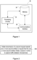
- Figure 1 illustrates a first entity 30 in accordance with an embodiment.
- the first entity 30 is for use in capturing traffic in a network.
- the first entity 30 may, for example, be a physical machine (e.g. a server) or a virtual machine (VM).
- the first entity 30 may be a controller.
- the controller may also be referred to herein as a traffic capture controller.
- the first entity 30 comprises processing circuitry (or logic) 32.
- the processing circuitry 32 controls the operation of the first entity 30 and can implement the method described herein in respect of the first entity 30.
- the processing circuitry 32 can be configured or programmed to control the first entity 30 in the manner described herein.
- the processing circuitry 32 can comprise one or more hardware components, such as one or more processors, one or more processing units, one or more multi-core processors and/or one or more modules.
- each of the one or more hardware components can be configured to perform, or is for performing, individual or multiple steps of the method described herein in respect of the first entity 30.
- the processing circuitry 32 can be configured to run software to perform the method described herein in respect of the first entity 30.
- the software may be containerised according to some embodiments.
- the processing circuitry 32 may be configured to run a container to perform the method described herein in respect of the first entity 30.
- the processing circuitry 32 of the first entity 30 is configured to, in response to a first request to initiate a session in which to capture traffic between microservices, initiate transmission of a second request towards one or more second entities.
- the second request is a request that the one or more second entities initiate the session and the second request comprises one or more capture filters generated for use by the one or more second entities to capture the traffic between the microservices.
- the microservices are distributed across a plurality of nodes in the network.
- the first entity 30 may optionally comprise a memory 34.
- the memory 34 of the first entity 30 can comprise a volatile memory or a non-volatile memory.
- the memory 34 of the first entity 30 may comprise a non-transitory media. Examples of the memory 34 of the first entity 30 include, but are not limited to, a random access memory (RAM), a read only memory (ROM), a mass storage media such as a hard disk, a removable storage media such as a compact disk (CD) or a digital video disk (DVD), and/or any other memory.
- RAM random access memory
- ROM read only memory
- CD compact disk
- DVD digital video disk
- the processing circuitry 32 of the first entity 30 can be connected to the memory 34 of the first entity 30.
- the memory 34 of the first entity 30 may be for storing program code or instructions which, when executed by the processing circuitry 32 of the first entity 30, cause the first entity 30 to operate in the manner described herein in respect of the first entity 30.
- the memory 34 of the first entity 30 may be configured to store program code or instructions that can be executed by the processing circuitry 32 of the first entity 30 to cause the first entity 30 to operate in accordance with the method described herein in respect of the first entity 30.
- the memory 34 of the first entity 30 can be configured to store any information, data, messages, requests, responses, indications, notifications, signals, or similar, that are described herein.
- the processing circuitry 32 of the first entity 30 may be configured to control the memory 34 of the first entity 30 to store information, data, messages, requests, responses, indications, notifications, signals, or similar, that are described herein.
- the first entity 30 may optionally comprise a communications interface 36.
- the communications interface 36 of the first entity 30 can be connected to the processing circuitry 32 of the first entity 30 and/or the memory 34 of first entity 30.
- the communications interface 36 of the first entity 30 may be operable to allow the processing circuitry 32 of the first entity 30 to communicate with the memory 34 of the first entity 30 and/or vice versa.
- the communications interface 36 of the first entity 30 may be operable to allow the processing circuitry 32 of the first entity 30 to communicate with a second entity, a third entity, and/or any other entity.
- the communications interface 36 of the first entity 30 can be configured to transmit and/or receive information, data, messages, requests, responses, indications, notifications, signals, or similar, that are described herein.
- the processing circuitry 32 of the first entity 30 may be configured to control the communications interface 36 of the first entity 30 to transmit and/or receive information, data, messages, requests, responses, indications, notifications, signals, or similar, that are described herein.
- the first entity 30 is illustrated in Figure 1 as comprising a single memory 34, it will be appreciated that the first entity 30 may comprise at least one memory (i.e. a single memory or a plurality of memories) 34 that operate in the manner described herein.
- the first entity 30 is illustrated in Figure 1 as comprising a single communications interface 36, it will be appreciated that the first entity 30 may comprise at least one communications interface (i.e. a single communications interface or a plurality of communications interface) 36 that operate in the manner described herein.
- Figure 1 only shows the components required to illustrate an embodiment of the first entity 30 and, in practical implementations, the first entity 30 may comprise additional or alternative components to those shown.
- Figure 2 is a flowchart illustrating a method performed by a first entity 30 in accordance with an embodiment.
- the method is for capturing traffic in a network.
- the first entity 30 described earlier with reference to Figure 1 is configured to operate in accordance with the method of Figure 2 .
- the method can be performed by or under the control of the processing circuitry 32 of the first entity 30.
- transmission of a second request is initiated towards one or more second entities. More specifically, the processing circuitry 32 of the first entity 30 initiates the transmission of (e.g. itself transmits or causes another entity to transmit) the second request.
- the second request is a request that the one or more second entities initiate the session and the second request comprises one or more capture filters generated for use by the one or more second entities to capture the traffic between the microservices.
- the microservices are distributed across a plurality of nodes in the network.
- the one or more capture filters can be any type of filter that can capture the traffic between the microservices.
- the traffic that is captured can be limited to traffic that matches the one or more capture filters.
- the one or more capture filters can be configured to capture relevant traffic pertaining to the requested capture session.
- the one or more capture filters can be configured to determine the traffic to capture based on predefined criteria. Examples of such criteria include, but are not limited to, any one or more of an identity of microservices between which the traffic is to be captured, an (e.g.
- IP or MAC IP or MAC address of the plurality of nodes across which the microservices are distributed (such as an address of a target node for the traffic to be captured and/or an address of a destination node for the traffic to be captured), one or more ports exposed by the microservices in transmitting the traffic that is to be captured, one or more protocols used by the microservices to transmit the traffic that is to be captured, etc.
- the one or more filters may be expressed in terms of microservice types.
- a cloud native application is made up of several microservice types.
- a system may manage a variable number of microservices (or microservice instances). It may be of interest for an operator to capture traffic between two given microservice types (e.g. ms A and ms B). This implies that all the traffic initiated from any microservice of type ms A targeted to any microservice of type ms B, and vice versa.
- the filter may instead refer to "all traffic between ms A and ms B microservices". This can be advantageous when the number of microservices (or microservice instances) change over time, e.g.
- the one or more filters can be expressed in terms of names of individual microservices (or microservice instances).
- a microservice may expose different ports pertaining to different services offered.
- Port names can be predefined by an application or may be set (e.g. dynamically) at deployment time. In such cases, port numbers can be looked up in a service discovery feature.
- the one or more filters can be expressed in terms of port names directly, without needing to find out the actual port number determined at deployment time.
- the method performed by the first entity may comprise generating the one or more capture filters for use by the one or more second entities. More specifically, in some embodiments, the processing circuitry 32 of the first entity 30 can be configured to generate the one or more capture filters for use by the one or more second entities. In some embodiments, the one or more capture filters may be based on data identifying the traffic that is to be captured. The data identifying the traffic that is to be captured may be high-level data (such as high-level network details), whereas the one or more capture filters may identify the traffic that is to be captured using low-level data (such as low-level network details).
- the processing circuitry 32 of the first entity 30 may be configured to translate high-level data into low-level data for the purpose of generating the one or more capture filters.
- the one or more capture filters may be expressed in terms of microservice type names, instances, traffic port names and/or the translation to microservice instance 5-tuples.
- the method performed by the first entity 30 may comprise retrieving the data identifying the traffic that is to be captured. More specifically, in some embodiments, the processing circuitry 32 of the first entity 30 can be configured to retrieve the data identifying the traffic to be captured. In some embodiments, the first request to initiate the session in which to capture traffic between microservices may comprise the data identifying the traffic to be captured. Thus, in some embodiments, the data identifying the traffic that is to be captured may be retrieved from the first request.
- the method performed by the first entity 30 may comprise, in response to a change in the data identifying the traffic that is to be captured, updating the one or more capture filters based on the changed data. More specifically, in some embodiments, the processing circuitry 32 of the first entity 30 can be configured to update the one or more capture filters. In some embodiments, the one or more capture filters may be continuously or periodically updated. In some embodiments, the one or more capture filters may be updated based on runtime changes of the plurality of nodes. In some embodiments, the method performed by the first entity 30 may comprise initiating transmission of the one or more updated capture filters towards the one or more second entities for use by the one or more second entities to capture the traffic between the microservices. More specifically, in some embodiments, the processing circuitry 32 of the first entity 30 can be configured to initiate the transmission of (e.g. itself transmit or cause another entity to transmit) the one or more updated capture filters.
- the processing circuitry 32 of the first entity 30 can be configured to initiate the transmission of (e.g. itself transmit or cause another entity to transmit)
- the data identifying the traffic that is to be captured may comprise data identifying the microservices between which the traffic is to be captured, data indicative of the plurality of nodes across which the microservices are distributed, data indicative of one or more ports exposed by the microservices in transmitting the traffic that is to be captured, and/or data indicative of one or more protocols used by the microservices to transmit the traffic that is to be captured.
- the data indicative of the plurality of nodes across which the microservices are distributed may comprise one or more internet protocol (IP) addresses or media access control (MAC) addresses of the plurality of nodes across which the microservices are distributed.
- IP internet protocol
- MAC media access control
- the method performed by the first entity 30 may comprise identifying the one or more second entities, e.g. identifying one or more second entities involved in handling the related traffic flows. More specifically, in some embodiments, the processing circuitry 32 of the first entity 30 can be configured to identify the one or more second entities.
- the method performed by the first entity 30 may comprise initiating transmission of a third request towards one or more third entities.
- the third request is a request that the one or more third entities monitor traffic flow between the microservices during the session.
- the processing circuitry 32 of the first entity 30 can be configured to initiate the transmission of (e.g. itself transmit or cause another entity to transmit) the third request.
- the traffic flow between microservices may comprise one or more connections between the microservices, such as a one or more transmission control protocol (TCP) connections between the microservices, one or more user datagram protocol (UDP) connections between the microservices, and/or any other type of connection(s) between the microservices.
- TCP transmission control protocol
- UDP user datagram protocol
- the method performed by the first entity 30 may comprise, in response to receiving a fourth request to terminate traffic capture, acquiring from the one or more second entities the traffic captured between the microservices during the session. More specifically, the processing circuitry 32 of the first entity 30 can be configured to acquire the traffic captured between microservices.
- the method performed by the first entity 30 may comprise initiating transmission of a message, which comprises information associated with the traffic captured between the microservices during the session. More specifically, the processing circuitry 32 of the first entity 30 can be configured to initiate the transmission of (e.g. itself transmit or cause another entity to transmit) the message. In some embodiments, the method performed by the first entity 30 may comprise generating the information associated with the traffic captured between the microservices during the traffic capture session. More specifically, the processing circuitry 32 of the first entity 30 can be configured to generate this information according to some embodiments.
- the information associated with the traffic captured between the microservices during the traffic capture session may be in a human-readable format.
- the information associated with the traffic captured between the microservices during the traffic capture session may comprise at least one of the traffic captured between the microservices during the session, one or more keys used to encrypt the traffic captured between the microservices during the session, one or more references or links for downloading the traffic captured between the microservices during the session, information identifying the microservices between which the traffic is captured during the session, information identifying one or more instances of the microservices between which the traffic is captured during the session, and one or more ports exposed by the microservices in transmitting the traffic captured during the session.
- the traffic to be captured during the session may comprise encrypted traffic.
- the method may comprise acquiring, from one or more third entities, details for decrypting the encrypted traffic. More specifically, the processing circuitry 32 of the first entity 30 can be configured to acquire, from the one or more third entities, the details for decrypting the encrypted traffic.
- the details may comprise a private key and/or a pre-master secret key used to encrypt the traffic captured during the session.
- FIG. 3 illustrates a second entity 40 in accordance with an embodiment.
- the second entity 40 is for capturing traffic in a network.
- the second entity 40 may, for example, be a physical machine (e.g. a server) or a virtual machine (VM).
- the second entity 40 may be an agent, such as a network agent.
- the agent may also be referred to herein as a traffic capture agent.
- the second entity 40 comprises processing circuitry (or logic) 42.
- the processing circuitry 42 controls the operation of the second entity 40 and can implement the method described herein in respect of the second entity 40.
- the processing circuitry 42 can be configured or programmed to control the second entity 40 in the manner described herein.
- the processing circuitry 42 can comprise one or more hardware components, such as one or more processors, one or more processing units, one or more multi-core processors, and/or one or more modules.
- each of the one or more hardware components can be configured to perform, or is for performing, individual or multiple steps of the method described herein in respect of the second entity 40.
- the processing circuitry 42 can be configured to run software to perform the method described herein in respect of the second entity 40.
- the software may be containerised according to some embodiments.
- the processing circuitry 42 may be configured to run a container to perform the method described herein in respect of the second entity 40.
- the processing circuitry 42 of the second entity 40 is configured to, in response to a second request to start a session in which to capture traffic between microservices, initiate a transmission of a fifth request to control a tool in one or more of the plurality of nodes using one or more capture filters to capture the traffic between the microservices.
- the microservices are distributed across a plurality of nodes in the network and the second request comprises the one or more capture filters generated for use in capturing the traffic between the microservices.
- the second entity 40 may optionally comprise a memory 44.
- the memory 44 of the second entity 40 can comprise a volatile memory or a non-volatile memory.
- the memory 44 of the second entity 40 may comprise a non-transitory media. Examples of the memory 44 of the second entity 40 include, but are not limited to, a random access memory (RAM), a read only memory (ROM), a mass storage media such as a hard disk, a removable storage media such as a compact disk (CD) or a digital video disk (DVD), and/or any other memory.
- RAM random access memory
- ROM read only memory
- CD compact disk
- DVD digital video disk
- the processing circuitry 42 of the second entity 40 can be connected to the memory 44 of the second entity 40.
- the memory 44 of the second entity 40 may be for storing program code or instructions which, when executed by the processing circuitry 42 of the second entity 40, cause the second entity 40 to operate in the manner described herein in respect of the second entity 40.
- the memory 44 of the second entity 40 may be configured to store program code or instructions that can be executed by the processing circuitry 42 of the second entity 40 to cause the second entity 40 to operate in accordance with the method described herein in respect of the second entity 40.
- the memory 44 of the second entity 40 can be configured to store any information, data, messages, requests, responses, indications, notifications, signals, or similar, that are described herein.
- the processing circuitry 42 of the second entity 40 may be configured to control the memory 44 of the second entity 40 to store information, data, messages, requests, responses, indications, notifications, signals, or similar, that are described herein.
- the second entity 40 may optionally comprise a communications interface 46.
- the communications interface 46 of the second entity 40 can be connected to the processing circuitry 42 of the second entity 40 and/or the memory 44 of second entity 40.
- the communications interface 46 of the second entity 40 may be operable to allow the processing circuitry 42 of the second entity 40 to communicate with the memory 44 of the second entity 40 and/or vice versa.
- the communications interface 46 of the second entity 40 may be operable to allow the processing circuitry 42 of the second entity 40 to communicate with the first entity 30, a third entity, and/or any other entity.
- the communications interface 46 of the second entity 40 can be configured to transmit and/or receive information, data, messages, requests, responses, indications, notifications, signals, or similar, that are described herein.
- the processing circuitry 42 of the second entity 40 may be configured to control the communications interface 46 of the second entity 40 to transmit and/or receive information, data, messages, requests, responses, indications, notifications, signals, or similar, that are described herein.
- the second entity 40 is illustrated in Figure 3 as comprising a single memory 44, it will be appreciated that the second entity 40 may comprise at least one memory (i.e. a single memory or a plurality of memories) 44 that operate in the manner described herein.
- the second entity 40 is illustrated in Figure 3 as comprising a single communications interface 46, it will be appreciated that the second entity 40 may comprise at least one communications interface (i.e. a single communications interface or a plurality of communications interface) 46 that operate in the manner described herein.
- Figure 3 only shows the components required to illustrate an embodiment of the second entity 40 and, in practical implementations, the second entity 40 may comprise additional or alternative components to those shown.
- Figure 4 is a flowchart illustrating a method performed by a second entity 40 in accordance with an embodiment.
- the method is for capturing traffic in a network.
- the second entity 40 described earlier with reference to Figure 3 is configured to operate in accordance with the method of Figure 4 .
- the method can be performed by or under the control of the processing circuitry 42 of the second entity 40.
- transmission of a fifth request is initiated to control a tool in one or more of a plurality of nodes, using one or more capture filters to capture traffic between the microservices.
- the processing circuitry 42 of the second entity 40 initiates the transmission of (e.g. itself transmits or causes another entity to transmit) the fifth request according to some embodiments.
- the second request comprises the one or more capture filters generated for use in capturing the traffic between the microservices.
- the microservices are distributed across a plurality of nodes in the network.
- the method performed by the second entity 40 may comprise, in response to a fourth request to terminate the session, initiating transmission of a sixth request to control the tool in the one or more of the plurality of nodes to terminate the capture of traffic between the microservices.
- the processing circuitry 42 of the second entity 40 can be configured to transmit (e.g. itself transmits or causes another entity to transmit) the sixth request according to some embodiments.
- one or more of the plurality of nodes in the network may comprise the second entity 40.
- FIG. 5 illustrates a third entity 50 in accordance with an aspect.
- the third entity 50 is for monitoring traffic flows in a network.
- the third entity 50 may, for example, be a physical machine (e.g. a server) or a virtual machine (VM).
- the third entity 50 may be a sidecar, e.g. that runs in one or more microservices.
- the sidecar may also be referred to herein as a traffic capture sidecar.
- the third entity 50 comprises processing circuitry (or logic) 52.
- the processing circuitry 52 controls the operation of the third entity 50 and can implement the method described herein in respect of the third entity 50.
- the processing circuitry 52 can be configured or programmed to control the third entity 50 in the manner described herein.
- the processing circuitry 52 can comprise one or more hardware components, such as one or more processors, one or more processing units, one or more multi-core processors, and/or one or more modules.
- each of the one or more hardware components can be configured to perform, or is for performing, individual or multiple steps of the method described herein in respect of the third entity 50.
- the processing circuitry 52 can be configured to run software to perform the method described herein in respect of the third entity 50.
- the software may be containerised according to some embodiments.
- the processing circuitry 52 may be configured to run a container to perform the method described herein in respect of the third entity 50.
- the processing circuitry 52 of the third entity 50 is configured to monitor one or more traffic flows between microservices distributed across a plurality of nodes in the network and between which traffic is to be captured during a session.
- the third entity 50 may optionally comprise a memory 54.
- the memory 54 of the third entity 50 can comprise a volatile memory or a non-volatile memory.
- the memory 54 of the third entity 50 may comprise a non-transitory media. Examples of the memory 54 of the third entity 50 include, but are not limited to, a random access memory (RAM), a read only memory (ROM), a mass storage media such as a hard disk, a removable storage media such as a compact disk (CD) or a digital video disk (DVD), and/or any other memory.
- RAM random access memory
- ROM read only memory
- CD compact disk
- DVD digital video disk
- the processing circuitry 52 of the third entity 50 can be connected to the memory 54 of the third entity 50.
- the memory 54 of the third entity 50 may be for storing program code or instructions which, when executed by the processing circuitry 52 of the third entity 50, cause the third entity 50 to operate in a manner described herein in respect of the third entity 50.
- the memory 54 of the third entity 50 may be configured to store program code or instructions that can be executed by the processing circuitry 52 of the third entity 50 to cause the third entity 50 to operate in accordance with the method described herein in respect of the third entity 50.
- the memory 54 of the third entity 50 can be configured to store any information, data, messages, requests, responses, indications, notifications, signals, or similar, that are described herein.
- the processing circuitry 52 of the third entity 50 may be configured to control the memory 54 of the third entity 50 to store information, data, messages, requests, responses, indications, notifications, signals, or similar, that are described herein.
- the third entity 50 may optionally comprise a communications interface 56.
- the communications interface 56 of the third entity 50 can be connected to the processing circuitry 52 of the third entity 50 and/or the memory 54 of third entity 50.
- the communications interface 56 of the third entity 50 may be operable to allow the processing circuitry 52 of the third entity 50 to communicate with the memory 54 of the third entity 50 and/or vice versa.
- the communications interface 56 of the third entity 50 may be operable to allow the processing circuitry 52 of the third entity 50 to communicate with the first entity 30, the second entity 40, and/or any other entity.
- the communications interface 56 of the third entity 50 can be configured to transmit and/or receive information, data, messages, requests, responses, indications, notifications, signals, or similar, that are described herein.
- the processing circuitry 52 of the third entity 50 may be configured to control the communications interface 56 of the third entity 50 to transmit and/or receive information, data, messages, requests, responses, indications, notifications, signals, or similar, that are described herein.
- the third entity 50 is illustrated in Figure 5 as comprising a single memory 54, it will be appreciated that the third entity 50 may comprise at least one memory (i.e. a single memory or a plurality of memories) 54 that operate in the manner described herein.
- the third entity 50 is illustrated in Figure 5 as comprising a single communications interface 56, it will be appreciated that the third entity 50 may comprise at least one communications interface (i.e. a single communications interface or a plurality of communications interface) 56 that operate in the manner described herein.
- Figure 5 only shows the components required to illustrate an embodiment of the third entity 50 and, in practical implementations, the third entity 50 may comprise additional or alternative components to those shown.
- Figure 6 is a flowchart illustrating a method performed by a third entity 50 in accordance with an aspect.
- the method is for monitoring traffic flows in a network.
- the third entity 50 described earlier with reference to Figure 5 is configured to operate in accordance with the method of Figure 6 .
- the method can be performed by or under the control of the processing circuitry 52 of the third entity 50
- one or more traffic flows are monitored between microservices distributed across a plurality of nodes in the network and between which traffic is to be captured during a session. More specifically, the processing circuitry 52 of the third entity 50 monitors the traffic flows between the microservices. In some embodiments, monitoring the one or more traffic flows may be in response to a third request to monitor the one or more traffic flows.
- the traffic to be captured during the session may comprise encrypted traffic.
- details for decrypting the encrypted traffic during the session may be acquired.
- the processing circuitry 52 of the third entity 50 can be configured to acquire the details for decrypting encrypted traffic.
- the details for decrypting the encrypted traffic may be acquired from one or more of the microservices.
- the method performed by the third entity 50 may comprise initiating transmission of a message towards a second entity.
- the message may comprise the details used for decrypting the encrypted traffic.
- the processing circuitry 52 of the third entity 50 may be configured to transmit (e.g. itself transmit or cause another entity to transmit) the message towards the second entity.
- the details for decrypting the encrypted traffic may comprise a private key and/or a pre-master secret key used to encrypt the traffic captured during the session.
- the method performed by the third entity 50 may comprise detecting the establishment of traffic flows between one or more of the microservices. More specifically, in some embodiments, the processing circuitry 52 of the third entity 50 may be configured to detect the establishment of traffic flows between one or more of the microservices.
- the method performed by the third entity may comprise, in response to receiving unencrypted traffic from one or more of the microservices, initiating transmission of the traffic towards another one or more of the microservices. More specifically, in some embodiments, the processing circuitry 52 of the third entity 50 may be configured to initiate transmission of (e.g. itself transmit or cause another entity to transmit) the unencrypted traffic towards another one or more of the microservices. In some embodiments, the transmission of the unencrypted traffic may be over an encrypted traffic flow.
- one or more of the plurality of nodes in the network may comprise the third entity 50.
- the system is for capturing and/or monitoring traffic in a network.
- the system can comprise one or more first entities 30 as described herein, one or more second entities 40 as described herein, and/or one or more third entities 50 as described herein.
- a method performed by the system can thus comprise the method described herein in respect of the first entity 30, the method described herein in respect of the second entity 40, and/or the method described herein in respect of the third entity 50.
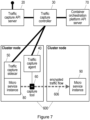
- Figure 7 illustrates such a system in accordance with an embodiment.
- the system illustrated in Figure 7 may be an orchestration platform, such as a container orchestration platform (COP).
- COP container orchestration platform
- the system can be based on Kubernetes.
- a person skilled in the art will appreciate that other system architectures are also possible.
- the system may be adapted to other COPs.
- the system comprises the first entity (e.g. a traffic capture controller) 30 described herein, the second entity (e.g. a traffic capture agent) 40 described herein, and the third entity (e.g. a traffic capture sidecar) 50 described herein.
- the first entity 30 can be configured to communicate with the second entity 40 and/or the third entity 50.
- the second entity 40 and/or the third entity 50 can be configured to communicate with the first entity 30.
- the first entity 30 can be configured to operate in the manner described earlier in respect of the first entity 30
- the second entity 40 can be configured to operate in the manner described earlier in respect of the second entity 40
- the third entity 50 can be configured to operate in the manner described earlier in respect of the third entity 50.
- the second entity 40 may be deployed in each of the plurality of nodes, e.g. in each node of a cluster.
- the second entity 40 may communicate with the first entity 30 to receive traffic capture commands and provide traffic capture results.
- the second entity 40 can communicate with the tool (e.g. capture tool) 60 referred to herein.
- the second entity 40 may operate the capture tool in one or more of the plurality of nodes to capture traffic.
- capture tools which may include common software applications, that can be used for the tool 60 referred to herein.
- the third entity 50 may be deployed with each microservice, or each microservice instance.
- the third entity 50 may be realised as a container. However, depending on the system capabilities, it can be a different process type. In a Kubernetes based system embodiment, the microservice and the third entity 50 may both be realized as containers.
- the microservice 80 and the third entity 50 may be deployed and (e.g. lifecycle) managed together, e.g. as a single group of microservices sharing resources.
- the third entity 50 may be able to extract a private key or a pre-master secret for each connection in which a microservice (or microservice instance) participates according to some embodiments.
- the system may comprise a fourth entity 20.
- the fourth entity 20 may, for example, be a server, such as an application programming interface (API) server, which may also be referred to as a traffic capture API server.
- API application programming interface
- the first entity 30 can be configured to communicate with the fourth entity 20 and vice versa.
- the fourth entity 20 can provide an interface for operating the traffic capture service described herein.
- the fourth entity 20 may expose an interface, such as a representational state transfer (REST)-based interface, a Graphical User Interface (GUI), or similar.
- REST representational state transfer
- GUI Graphical User Interface
- fourth entity 20 and the first entity 30 are illustrated as separate entities in the embodiment of Figure 7 , it will be appreciated that the fourth entity 20 and the first entity 30 may be a single entity according to other embodiments. That is, in some embodiments, the functionality described herein in respect of the fourth entity 20 and the first entity 30 may be performed by a single entity according to some embodiments.
- the system may comprise a fifth entity 70.
- the fifth entity 70 may, for example, be a server, such as an orchestration platform API server or a container orchestration platform (COP) API server.
- a Kubernetes API server is an example of a COP API server.
- the first entity 30 can be configured to communicate with the fifth entity 70 and vice versa.
- the fifth entity 70 may expose an interface (e.g. an API) to interact with the system illustrated in Figure 7 .
- the first entity 30 may use a REST-based interface to consume COP API services.
- the system can comprise the plurality (or cluster) of nodes 600 referred to herein across which the microservices 80, 90 described herein are distributed.
- it may be instances of a microservice 80, 90 that are distributed across the plurality of nodes 600.
- Each node of the plurality of nodes 600 may be referred to as a cluster node.
- a microservice (or microservice instance) 80 on one of the plurality of nodes 600 may transmit traffic 606 towards a microservice (or microservice instance) 90 on another one of the plurality of nodes 600.
- the traffic 606 may be an encrypted traffic flow.
- one or more of the plurality of nodes 600 may comprise the tool 60.
- Figures 8a -b is a signalling diagram illustrating an exchange of signals in a system according to an embodiment. More specifically, Figures 8a-b illustrate the creation of a capture session in accordance with an embodiment.
- the system may be as illustrated in Figure 7 according to some embodiments.
- the system illustrated in Figures 8a-b comprises a first entity (e.g. controller) 30 as described earlier, a second entity (e.g. agent) 40 as described earlier, and a third entity (e.g. sidecar) 50 as described earlier.
- the third entity 50 can be associated with a first microservice 80 (which may also be referred to herein as microservice A).
- the system illustrated in Figures 8a-b also comprises a user (or a user equipment, UE) 10, a fourth entity 20, a fifth entity 70, and a capture tool 60.
- UE user equipment
- the user (e.g. via a UE) 10 sets up a session in which to capture traffic.
- the user (e.g. via a UE) 10 identifies the traffic that is to be captured.
- the user (e.g. via a UE) 10 may include in the request other details, such as a duration for the session in which to capture traffic, a maximum number of packets to capture in the session, etc.
- the user 10 transmits a request towards the fourth entity 20, which is a request to capture traffic between microservices 80, 90 that are distributed across a plurality of nodes 600 in the network.
- the fourth entity 20 may validate the request from the user (e.g. the UE) 10.
- the validation may comprise authenticating and/or authorizing the user (or the UE) 10.
- the fourth entity 20 transmits a request to the first entity 30, which is a request to initiate the session in which to capture traffic 606 between microservices. This request is referred to herein as the first request.
- the fourth entity 20 may transmit a response to the user (e.g. UE), which can comprise details associated with the session in which traffic is to be captured, such as an identifier to be used by the user to refer to the session in subsequent messages.
- the first entity 30 may retrieve the data identifying the traffic 606 that is to be captured.
- the one or more capture filters may be generated based on this data.
- the first entity 30 may generate (or prepare) the one or more capture filters according to some embodiments.
- the capture filters may be low-level capture filters (e.g. filters expressed in terms of 5-tuples).
- the data identifying the traffic 606 that is to be captured may, for example, comprise data identifying the microservices 80, 90 between which the traffic 606 is to be captured, data indicative of the plurality of nodes 600 across which the microservices 80, 90 are distributed, data indicative of one or more ports exposed by the microservices 80, 90 in transmitting the traffic 606 that is to be captured, and/or data indicative of one or more protocols used by the microservices 80, 90 to transmit the traffic 606 that is to be captured.
- the generation of the one or more capture filters may comprise the first entity 30 determining the traffic ports participating in the traffic capture.
- the first entity 30 may query the fifth entity (e.g. COP API server) 70 to obtain the port numbers.
- the fifth entity (e.g. COP API) 70 may provide the port numbers (e.g. corresponding to the port names of the microservices 80, 90).
- the first entity 30 may use that information to create a port number (and protocol) part of the one or more (e.g. low-level) capture filters.
- the generation of the one or more capture filters may comprise the first entity 30 determining the microservices (or microservice instances) participating in the traffic capture.
- the first entity 30 may query the fifth entity (e.g. COP API server) 70 to obtain the microservice (or microservice instance) details.
- the fifth entity (e.g. COP API) 70 may provide the microservice details.
- the first entity 30 may use the provided information to, for example, extract the addresses (e.g.
- IP addresses of the microservices (or microservice instances) to create an addresses part of the one or more (e.g. low-level) capture filters, and/or extract the node each microservice (or microservice instance) is running in order to determine the second entity (e.g. agent) 40 to contact.
- the first entity 30 may create a subscription in the fifth entity (e.g. COP API) to be notified whenever the microservice (or microservice instance) information changes (e.g. due to scaling or termination of microservices, or relocation between nodes of the plurality of nodes).
- the fifth entity e.g. COP API
- the first entity 30 upon receiving such a notification, to update the capture filters during the session in which traffic is captured.
- This update can be performed automatically according to some embodiments.
- the update may, for example, comprise adding or removing (IP) addresses and/or port numbers, as the runtime state of the plurality of nodes evolves.
- IP adding or removing
- the first entity 30 can thus collect data identifying the traffic 606 that is to be captured and, as illustrated at block 720 of Figure 8b , process this data to generate the one or more (e.g. low-level) capture filters according to some embodiments.
- the first entity 30 may distribute the one or more capture filters among the different second entities (e.g. agents) 40 involved.
- one or more second entities initiate transmission of a request to control a tool (or capture tool) 60 in one or more of the plurality of nodes 600 using the one or more capture filters to capture the traffic 606 between the microservices 80, 90.
- This request is referred to herein as the fifth request.
- the first entity 30 may transmit a start capture session request message comprising the (e.g. low-level) capture filters applicable to it.
- the one or more second entities execute the tool 60 using the (e.g. low-level) filters as parameters.
- traffic is captured by the tool 60. More specifically, traffic matching the filters is captured by the tool 60.
- the first entity 30 may initiate transmission of a request towards one or more (e.g. each) third entities (e.g. sidecars) 50, where the request is a request that the one or more third entities 50 monitor traffic flows between the microservices 80, 90 during the session.
- This request is referred to herein as the third request.
- the third request may instruct the one or more third entities to supervise connections (e.g. TLS connections) created or received by the microservices 80, 90.
- the one or more third entities 50 monitor one or more traffic flows between microservices 80, 90 distributed across a plurality of nodes 600 in the network and between which traffic 606 is to be captured during a session.
- the monitoring of traffic flows may be performed in order to provide details needed for decrypting encrypted traffic. At this point, the setup of the capture session is complete.
- a first microservice (or microservice instance) 80 may create a new connection (e.g. TLS connection) towards a second microservice (or microservice instance) 90 (hereinafter referred to as "ms B").
- ms A a new connection
- ms B a second microservice
- the microservices may natively implement the protection of connections (e.g. with TLS), an example of which will be described with reference to Error! Reference source not found..
- the microservices may delegate the protection of connections (e.g. with TLS) to a third entity (e.g. sidecar) 50, an example of which will be described with reference to Error! Reference source not found..
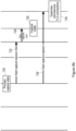
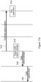
- Figure 9 is a signalling diagram illustrating an exchange of signals in a system according to an embodiment. More specifically, Figure 9 illustrates traffic capture of connections, such as transmission control protocol (TCP) connections, user datagram protocol (UDP) connections, transport layer security (TLS) connections and/or datagram transport layer security (DTLS) connections, in accordance with an embodiment.
- TCP transmission control protocol
- UDP user datagram protocol
- TLS transport layer security
- DTLS datagram transport layer security
- the system may be as illustrated in Figure 7 according to some embodiments.
- the system illustrated in Figure 9 comprises a first entity (e.g. controller) 30 as described earlier and a third entity (e.g. sidecar) 50 as described earlier.
- the system illustrated in Figure 9 also comprises a first microservice 80 (which will be referred to as "ms A”), a capture tool 60, and a second microservice 90 (which will be referred to as “ms B").
- the third entity 50 can be associated with the first microservice 80.
- ms A may open a connection towards ms B.
- the connection may be a transmission control protocol (TCP) connection or a user datagram protocol (UDP) connection.
- TCP transmission control protocol
- UDP user datagram protocol
- ms A may complete a (e.g. TCP) connection handshake with ms B.
- the tool (or capture tool) 60 can capture (and may record) the traffic for the handshake.
- a (e.g. TLS) handshake for securing the traffic may take place between ms A and ms B.
- the third entity (e.g. sidecar) 50 associated with ms A may detect establishment of traffic flows between ms A and ms B.
- the third entity (e.g. sidecar) 50 associated with ms A may detect the new (e.g. TLS) connection.
- the third entity 50 may supervise traces generated by a (e.g. TLS) library used by ms A, such as by configuring the library to emit such traces.
- the third entity 50 may acquire details for decrypting the encrypted traffic captured during the session.
- the third entity 50 may extract a private key of ms A used for the handshake illustrated by arrow 806, a pre-master secret used to derive a symmetric session key, or both.
- the third entity 50 may initiate transmission of a message towards the first entity 30.
- the message can comprise the details for decrypting the encrypted traffic captured during the session and/or details of the new (e.g. TLS) connection to the first entity 30. These details may, for example, comprise an identity of the connection (e.g. a connection 5-tuple), a timestamp for the connection, and/or the private key and/or pre-master secret mentioned earlier.
- the tool 60 may capture (and optionally also record) the traffic pertaining to the (e.g. TLS) connection between ms A and ms B.
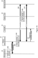
- Figure 10 is a signalling diagram illustrating an exchange of signals in a system according to an embodiment. More specifically, Figure 10 illustrates traffic capture of connections, such as transmission control protocol (TCP) connections, user datagram protocol (UDP) connections, transport layer security (TLS) connections and/or datagram transport layer security (DTLS) connections, in accordance with an embodiment.
- TCP transmission control protocol
- UDP user datagram protocol
- TLS transport layer security
- DTLS datagram transport layer security
- the system may be as illustrated in Figure 7 according to some embodiments.
- the system illustrated in Figure 10 comprises a first entity (e.g. controller) 30 as described earlier and a third entity (e.g. sidecar) 50 as described earlier.
- the system illustrated in Figure 10 also comprises a first microservice 80 (which will be referred to as "ms A”), a capture tool 60, and a second microservice 90 (which will be referred to as “ms B").
- the third entity 50 can be associated with the first microservice.
- ms A may open a regular (e.g. non-TLS) connection towards ms B (e.g. a TCP connection).
- the third entity (e.g. sidecar) 50 can intercept this connection and complete the (e.g. TCP) connection handshake.
- the third entity 50 may proxy the connection to ms B.
- the third entity 50 can complete a (e.g. TCP) connection handshake with ms B.
- the third entity 50 may initiate transmission of the traffic towards ms B. This transmission may be over an encrypted traffic flow.
- the tool (or capture tool) 60 captures (and optionally also records) the traffic for the connection handshake.
- the third entity 50 may perform a (e.g. TLS) handshake on the proxied connection. Once this handshake is complete, as illustrated by arrow 912 of Figure 10 , the third entity 50 may initiate transmission of a message towards the first entity 30.
- the message can comprise the details for decrypting the encrypted traffic captured during the session and/or details of the proxied (e.g. TLS) connection to the first entity 30. These details may, for example, comprise an identity of the connection (e.g.
- the tool 60 may capture (and optionally also record) the traffic pertaining to the (e.g. TLS) connection between ms A and ms B.
- the traffic pertaining to the (e.g. TLS) connection between ms A and ms B may capture (and optionally also record) the traffic pertaining to the (e.g. TLS) connection between ms A and ms B.
- Figures 11a -b is a signalling diagram illustrating an exchange of signals in a system according to an embodiment. More specifically, Figures 11a-b illustrate the finalisation of a capture session in accordance with an embodiment.
- the system may be as illustrated in Figure 7 according to some embodiments.
- the system illustrated in Figure 11a-b comprises a first entity (e.g. controller) 30 as described earlier, a second entity (e.g. an agent) 40 as described earlier and a third entity (e.g. sidecar) 50 as described earlier.
- the system illustrated in Figure 11a-b also comprises a user (e.g. a UE) 10, a fourth entity (e.g. an API server) 20, and a capture tool 60.
- the third entity 50 can be associated with a first microservice 80.
- the user (e.g. via the UE) 10 may indicate that an ongoing capture session can be finalised.
- the user (e.g. the UE) 10 may transmit a request to end traffic capture to the fourth entity 20.
- the fourth entity 20 can validate the request.
- the fourth entity 20 may transmit a request (which is referred to herein as the fourth request) to terminate the capture of traffic to the first entity 30. The first entity 30 thus receives this request.
- the first entity 30 can identify the one or more second entities 40 participating in the capture session. As illustrated by arrow 1008 of Figure 11a , the first entity 30 may transmit the request (which is referred to herein as the fourth request) to terminate the capture of traffic to each of the one or more second entities 40. Thus, the (fourth) request to terminate the capture of traffic may be transmitted towards the one or more second entities 40 via the first entity 30. As illustrated by arrow 1010 of Figure 11a , the one or more second entities 40 initiate transmission of a request (which is referred to herein as the sixth request) to control the tool 60 in the one or more of the plurality of nodes 600 to terminate the capture of the traffic 606 between the microservices.
- a request which is referred to herein as the sixth request
- each of the one or more second entities 40 can stop the tool 60 in this way.
- the one or more second entities 40 may fetch any generated capture files.
- the first entity 30 may (e.g. securely) transfer the generated capture files to the first entity 30.
- the first entity 30 may store the generated capture files.
- the first entity 30 may initiate transmission of a request to terminate the capture of traffic to each of the third entities 50 participating in the capture session.
- each third entity 50 can stop monitoring one or more traffic flows between microservices, e.g. stop supervising the setup of (e.g. TLS) connections for the capture session.
- the first entity 30 can generate information associated with the traffic captured between the microservices during the session.
- the first entity 30 can create a traffic capture package.
- the information that may be generated include, but are not limited to, files to provide (e.g. human-readable) names for microservices, microservice instances, and traffic ports, or a link to a downloadable file containing all those files, files to provide private keys and/or pre-master secrets of all (e.g. TLS) connections captured or a link to a downloadable file containing all those files, traffic capture files or a link to a downloadable file containing all those files.
- the first entity 30 may merge all traffic files into a single file.
- the first entity 30 may, for example, use a timestamp and 5-tuple attribute of each captured packet of the traffic to remove duplicates and/or order them.
- the first entity 30 may initiate transmission of a message to the fourth entity 20.
- the message can comprise information associated with the traffic captured between the microservices during the session. For example, where a traffic capture package is created, the first entity 30 may send the created package to the fourth entity 20. As illustrated by arrow 1022 of Figure 11b , the fourth entity 20 may, in turn, initiate transmission of the message (e.g. the created package) to the user (e.g. the UE) 10.
- the message may be referred to as a traffic capture result response.
- Figure 12 is a block diagram illustrating a first entity 1100 in accordance with an embodiment.
- the first entity 1100 comprises a transmission initiating module 1102 configured to, in response to a first request to initiate a session in which to capture traffic between microservices, initiate transmission of a second request towards one or more second entities.
- the second request is a request that the one or more second entities initiate the session and the second request comprises one or more capture filters generated for use by the one or more second entities to capture the traffic between the microservices.
- the microservices are distributed across a plurality of nodes in a network.
- the first entity 1100 may operate in the manner described herein in respect of the first entity.
- FIG. 13 is a block diagram illustrating a second entity 1200 in accordance with an embodiment.
- the second entity 1200 comprises a transmission initiating module 1202 configured to, in response to a second request to start a session in which to capture traffic between microservices, initiate transmission of a fifth request to control a tool in one or more of a plurality of nodes in a network using one or more capture filters to capture the traffic between the microservices.
- the microservices are distributed across the plurality of nodes in the network and the second request comprises the one or more capture filters generated for use in capturing the traffic between the microservices.
- the second entity 1200 may operate in the manner described herein in respect of the second entity.
- FIG 14 is a block diagram illustrating a third entity 1300 in accordance with an aspect.
- the third entity 1300 comprises a monitoring module 1302 configured to monitor one or more traffic flows between microservices distributed across a plurality of nodes in a network and between which traffic is to be captured during a session.
- the third entity 1300 may operate in the manner described herein in respect of the third entity.
- a computer program comprising instructions which, when executed by processing circuitry (such as the processing circuitry 32 of the first entity 30 described earlier, the processing circuitry 42 of the second entity 40 described earlier, and/or the processing circuitry 52 of the third entity 50 described earlier), cause the processing circuitry to perform at least part of the method described herein.
- processing circuitry such as the processing circuitry 32 of the first entity 30 described earlier, the processing circuitry 42 of the second entity 40 described earlier, and/or the processing circuitry 52 of the third entity 50 described earlier
- a computer program product embodied on a non- transitory machine-readable medium, comprising instructions which are executable by processing circuitry (such as the processing circuitry 32 of the first entity 30 described earlier, the processing circuitry 42 of the second entity 40 described earlier, and/or the processing circuitry 52 of the third entity 50 described earlier) to cause the processing circuitry to perform at least part of the method described herein.
- a computer program product comprising a carrier containing instructions for causing processing circuitry (such as the processing circuitry 32 of the first entity 30 described earlier, the processing circuitry 42 of the second entity 40 described earlier, and/or the processing circuitry 52 of the third entity 50 described earlier) to perform at least part of the method described herein.
- the carrier can be any one of an electronic signal, an optical signal, an electromagnetic signal, an electrical signal, a radio signal, a microwave signal, or a computer-readable storage medium.
- the first entity functionality, the second entity functionality, and/or the third entity functionality described herein can be performed by hardware.
- any one or more of the first entity 30, the second entity 40, and the third entity 50 described herein can be a hardware node.
- optionally at least part or all of the first entity functionality, the second entity functionality, and/or the third entity functionality described herein can be virtualized.
- the functions performed by any one or more of the first entity 30, the second entity 40, and the third entity 50 described herein can be implemented in software running on generic hardware that is configured to orchestrate the node functionality.
- the any one or more of the first entity 30, the second entity 40, and the third entity 50 described herein can be a virtual node.
- at least part or all of the first entity functionality, the second entity functionality, and/or the third entity functionality described herein may be performed in a network enabled cloud.
- the first entity functionality, the second entity functionality, and/or the third entity functionality described herein may all be at the same location or at least some of the node functionality may be distributed.
- the technique can, for example, provide a (e.g. automated) traffic capture service to selectively capture (e.g. encrypted) traffic flows.
- the technique can also provide additional data (e.g. metadata) required to effectively analyse traffic, e.g. with regard to application monitoring and troubleshooting.
- the technique can provide an (e.g. automated) traffic capture service.
- the technique can remove, from the service user, the complexity associated with capturing and analysing encrypted traffic data in a highly distributed, dynamic, and massively scalable container orchestration platform.
- the technique can be used in cloud native applications as well as others.
Landscapes
- Engineering & Computer Science (AREA)
- Computer Networks & Wireless Communication (AREA)
- Signal Processing (AREA)
- Computer Security & Cryptography (AREA)
- Computer Hardware Design (AREA)
- Computing Systems (AREA)
- General Engineering & Computer Science (AREA)
- Technology Law (AREA)
- Data Exchanges In Wide-Area Networks (AREA)
Claims (17)
- Verfahren zum Verwenden beim Erfassen von Verkehr in einem Netzwerk, wobei das Verfahren durch eine erste Entität (30) durchgeführt wird, wobei das Verfahren Folgendes umfasst:
als Reaktion auf eine erste Anforderung (706), um eine Sitzung zu initiieren, in der Verkehr (606) zwischen Microservices (80, 90) zu erfassen ist, wobei die Microservices (80, 90) über eine Vielzahl von Knoten (600) in dem Netzwerk verteilt sind:
Initiieren einer Übertragung (300) einer zweiten Anforderung (722) in Richtung einer oder mehrerer zweiter Entitäten (40), wobei die zweite Anforderung (722) eine Anforderung ist, dass die eine oder die mehreren zweiten Entitäten (40) die Sitzung initiieren, und die zweite Anforderung (722) ein oder mehrere Erfassungsfilter umfasst, die zum Verwenden durch die eine oder die mehreren zweiten Entitäten (40) erzeugt werden, um den Verkehr (606) zwischen den Microservices (80, 90) zu erfassen. - Verfahren nach Anspruch 1, wobei das Verfahren Folgendes umfasst:
Erzeugen des einen oder der mehreren Erfassungsfilter zum Verwenden durch die eine oder die mehreren zweiten Entitäten (40), wobei das eine oder die mehreren Erfassungsfilter basierend auf Daten erzeugt werden, die den Verkehr (606), der zu erfassen ist, identifizieren. - Verfahren nach Anspruch 2, wobei:
die erste Anforderung (706) die Daten umfasst, die den Verkehr, der zu erfassen ist, identifizieren. - Verfahren nach Anspruch 2 oder 3, wobei das Verfahren Folgendes umfasst:
als Reaktion auf eine Änderung der Daten, die den Verkehr (606), der zu erfassen ist, identifizieren, Aktualisieren des einen oder der mehreren Erfassungsfilter basierend auf den geänderten Daten. - Verfahren nach Anspruch 4, wobei das Verfahren Folgendes umfasst:
Initiieren einer Übertragung des einen oder der mehreren aktualisierten Erfassungsfilter in Richtung der einen oder der mehreren zweiten Entitäten zum Verwenden durch die eine oder die mehreren zweiten Entitäten (40), um den Verkehr (606) zwischen den Microservices (80, 90) zu erfassen. - Verfahren nach einem der Ansprüche 2 bis 5, wobei:
die Daten, die den Verkehr (606), der zu erfassen ist, identifizieren, Folgendes umfassen:Daten, die die Microservices (80, 90) identifizieren, zwischen denen der Verkehr (606) zu erfassen ist;Daten, die die Vielzahl von Knoten (600) angeben, über die die Microservices (80, 90) verteilt sind;Daten, die einen oder mehrere Anschlüsse angeben, die durch die Microservices (80, 90) beim Übertragen des Verkehrs (606), der zu erfassen ist, freigelegt werden; und/oderDaten, die ein oder mehrere Protokolle angeben, die durch die Microservices (80, 90) dazu verwendet werden, den Verkehr (606), der zu erfassen ist, zu übertragen. - Verfahren nach einem der vorhergehenden Ansprüche, wobei das Verfahren Folgendes umfasst:Initiieren einer Übertragung einer dritten Anforderung (728) in Richtung einer oder mehrerer dritter Entitäten (50), wobei die dritte Anforderung (728) eine Anforderung ist, dass die eine oder die mehreren dritten Entitäten (50) Verkehrsströme zwischen den Microservices (80, 90) während der Sitzung überwachen;als Reaktion auf eine vierte Anforderung (1006), um die Erfassung von Verkehr zu beenden, Erhalten, von der einen oder den mehreren zweiten Entitäten (40), des Verkehrs, der während der Sitzung zwischen den Microservices (80, 90) erfasst wird; und/oderInitiieren einer Übertragung einer Nachricht (1020), wobei die Nachricht Informationen umfasst, die dem Verkehr zugeordnet sind, der während der Sitzung zwischen den Microservices (80, 90) erfasst wird.
- Verfahren nach Anspruch 7, wobei:
die Informationen, die dem Verkehr zugeordnet sind, der während der Sitzung zwischen den Microservices (80, 90) erfasst wird, mindestens eines von Folgendem umfassen:dem Verkehr, der während der Sitzung zwischen den Microservices (80, 90) erfasst wird;einem oder mehreren Schlüsseln, die dazu verwendet werden, den Verkehr zu verschlüsseln, der während der Sitzung zwischen den Microservices (80, 90) erfasst wird;einer oder mehreren Referenzen oder Verknüpfungen zum Herunterladen des Verkehrs, der während der Sitzung zwischen den Microservices (80, 90) erfasst wird;Informationen, die die Microservices (80, 90) identifizieren, zwischen denen der Verkehr während der Sitzung erfasst wird;Informationen, die eine oder mehrere Instanzen der Microservices (80, 90) identifizieren, zwischen denen der Verkehr während der Sitzung erfasst wird; undeinem oder mehreren Anschlüssen, die durch die Microservices (80, 90) beim Übertragen des Verkehrs, der während der Sitzung erfasst wird, freigelegt werden. - Verfahren nach einem der vorhergehenden Ansprüche, wobei:der Verkehr (606), der während der Sitzung zu erfassen ist, verschlüsselten Verkehr umfasst; unddas Verfahren Folgendes umfasst:
Erhalten (812), von einer oder mehreren dritten Entitäten (50), von Details zum Entschlüsseln des verschlüsselten Verkehrs. - Verfahren nach Anspruch 9, wobei:
die Details einen privaten Schlüssel und/oder einen Pre-Master-Secret-Schlüssel umfassen, die dazu verwendet werden, den Verkehr, der während der Sitzung erfasst wird, zu verschlüsseln. - Erste Entität (30), umfassend:
einen Verarbeitungsschaltkreis (32), der dazu konfiguriert ist, gemäß einem der Ansprüche 1 bis 10 betrieben zu werden. - Verfahren zum Erfassen von Verkehr in einem Netzwerk, wobei das Verfahren durch eine zweite Entität (40) durchgeführt wird, wobei das Verfahren Folgendes umfasst:
als Reaktion auf eine zweite Anforderung (722), um eine Sitzung zu starten, in der Verkehr (606) zwischen Microservices (80, 90) zu erfassen ist, wobei die Microservices (80, 90) über eine Vielzahl von Knoten (600) in dem Netzwerk verteilt sind und die zweite Anforderung (722) ein oder mehrere Erfassungsfilter umfasst, die zum Verwenden beim Erfassen des Verkehrs (606) zwischen den Microservices (80, 90) erzeugt werden:
Initiieren einer Übertragung (400) einer fünften Anforderung (724), um ein Werkzeug (60) in einem oder mehreren der Vielzahl von Knoten (600) unter Verwendung des einen oder der mehreren Erfassungsfilter zu steuern, um den Verkehr (606) zwischen den Microservices (80, 90) zu erfassen. - Verfahren nach Anspruch 12, wobei:
als Reaktion auf eine vierte Anforderung (1006, 1008), um die Sitzung zu beenden, Initiieren einer Übertragung einer sechsten Anforderung (1010), um das Werkzeug (60) in dem einen oder den mehreren der Vielzahl von Knoten (600) zu steuern, um die Erfassung des Verkehrs (606) zwischen den Microservices (80, 90) zu beenden. - Zweite Entität (40), umfassend:
einen Verarbeitungsschaltkreis (42), der dazu konfiguriert ist, gemäß Anspruch 12 oder 13 betrieben zu werden. - Verfahren, das durch ein System durchgeführt wird, wobei das Verfahren Folgendes umfasst:das Verfahren nach einem der Ansprüche 1 bis 10, das durch eine oder mehrere erste Entitäten (30) des Systems durchgeführt wird; und/oderdas Verfahren nach Anspruch 12 oder 13, das durch eine oder mehrere zweite Entitäten (40) des Systems durchgeführt wird; und Überwachen (500, 730), durch eine oder mehrere dritte Entitäten (50), eines oder mehrerer Verkehrsströme zwischen Microservices (80, 90), die über eine Vielzahl von Knoten (600) in dem Netzwerk verteilt sind und zwischen denen Verkehr (606) während einer Sitzung zu erfassen ist,wobei insbesondere das Überwachen (730) des einen oder der mehreren Verkehrsströme eine Reaktion auf eine dritte Anforderung (728) von einer der einen oder der mehreren ersten Entitäten (30) ist, um den einen oder die mehreren Verkehrsströme zu überwachen.
- System, umfassend:eine oder mehrere erste Entitäten (30) nach Anspruch 11; und/odereine oder mehrere zweite Entitäten (40) nach Anspruch 14; undeine oder mehrere dritte Entitäten (50), umfassend:einen Verarbeitungsschaltkreis (52), der dazu konfiguriert ist, gemäß einem Verfahren betrieben zu werden, das Überwachen (500, 730) eines oder mehrerer Verkehrsströme zwischen Microservices (80, 90) umfasst, die über eine Vielzahl von Knoten (600) in dem Netzwerk verteilt sind und zwischen denen Verkehr (606) während einer Sitzung zu erfassen ist,wobei insbesondere das Überwachen (730) des einen oder der mehreren Verkehrsströme eine Reaktion auf eine dritte Anforderung (728) von einer der einen oder der mehreren ersten Entitäten (30) ist, um den einen oder die mehreren Verkehrsströme zu überwachen.
- Computerprogramm, umfassend Anweisungen, die, wenn sie durch einen Verarbeitungsschaltkreis ausgeführt werden, den Verarbeitungsschaltkreis dazu veranlassen, das Verfahren nach einem der Ansprüche 1 bis 10 und/oder Anspruch 12 oder 13 durchzuführen.
Applications Claiming Priority (2)
| Application Number | Priority Date | Filing Date | Title |
|---|---|---|---|
| EP20382219 | 2020-03-23 | ||
| PCT/EP2020/062173 WO2021190771A1 (en) | 2020-03-23 | 2020-04-30 | Network traffic capture |
Publications (2)
| Publication Number | Publication Date |
|---|---|
| EP4128666A1 EP4128666A1 (de) | 2023-02-08 |
| EP4128666B1 true EP4128666B1 (de) | 2025-04-02 |
Family
ID=70189861
Family Applications (1)
| Application Number | Title | Priority Date | Filing Date |
|---|---|---|---|
| EP20721640.9A Active EP4128666B1 (de) | 2020-03-23 | 2020-04-30 | Erfassung von netzwerkverkehr |
Country Status (3)
| Country | Link |
|---|---|
| US (1) | US20240214431A1 (de) |
| EP (1) | EP4128666B1 (de) |
| WO (1) | WO2021190771A1 (de) |
Families Citing this family (2)
| Publication number | Priority date | Publication date | Assignee | Title |
|---|---|---|---|---|
| EP4320523A4 (de) | 2021-04-09 | 2024-12-25 | Netscout Systems, Inc. | Erzeugung synthetischer transaktionen mit paketen |
| US12526617B2 (en) | 2021-12-08 | 2026-01-13 | Palo Alto Networks, Inc. | Targeted PDU capture by a network device for roaming detection in wireless networks |
Family Cites Families (50)
| Publication number | Priority date | Publication date | Assignee | Title |
|---|---|---|---|---|
| US7627669B2 (en) * | 2003-05-21 | 2009-12-01 | Ixia | Automated capturing and characterization of network traffic using feedback |
| US8418241B2 (en) * | 2006-11-14 | 2013-04-09 | Broadcom Corporation | Method and system for traffic engineering in secured networks |
| US8443080B2 (en) * | 2010-05-06 | 2013-05-14 | Nec Laboratories America, Inc. | System and method for determining application dependency paths in a data center |
| US8813189B2 (en) * | 2011-11-18 | 2014-08-19 | Blue Coat Systems, Inc. | System and method for capturing network traffic |
| US9231892B2 (en) * | 2012-07-09 | 2016-01-05 | Vmware, Inc. | Distributed virtual switch configuration and state management |
| US10205648B1 (en) * | 2014-05-30 | 2019-02-12 | EMC IP Holding Company LLC | Network monitoring using traffic mirroring and encapsulated tunnel in virtualized information processing system |
| US9860309B2 (en) * | 2014-12-22 | 2018-01-02 | Vmware, Inc. | Hybrid cloud network monitoring system for tenant use |
| US9813323B2 (en) * | 2015-02-10 | 2017-11-07 | Big Switch Networks, Inc. | Systems and methods for controlling switches to capture and monitor network traffic |
| US10893100B2 (en) * | 2015-03-12 | 2021-01-12 | International Business Machines Corporation | Providing agentless application performance monitoring (APM) to tenant applications by leveraging software-defined networking (SDN) |
| US10764162B2 (en) * | 2015-03-25 | 2020-09-01 | Gigamon Inc. | In-fabric traffic analysis |
| US10536357B2 (en) * | 2015-06-05 | 2020-01-14 | Cisco Technology, Inc. | Late data detection in data center |
| US10382484B2 (en) * | 2015-06-08 | 2019-08-13 | Illusive Networks Ltd. | Detecting attackers who target containerized clusters |
| EP3208972B1 (de) * | 2016-02-16 | 2019-12-18 | Deutsche Telekom AG | Verfahren zur verbesserten verfolgung und/oder überwachung des netzknoten eines kommunikationsnetzwerks, kommunikationsnetzwerk, mehrere virtuelle maschinen, virtualisierte netzwerkfunktionsmanagerfunktionalität, programm und computerprogrammprodukt |
| US10212041B1 (en) * | 2016-03-04 | 2019-02-19 | Avi Networks | Traffic pattern detection and presentation in container-based cloud computing architecture |
| US9716617B1 (en) * | 2016-06-14 | 2017-07-25 | ShieldX Networks, Inc. | Dynamic, load-based, auto-scaling network security microservices architecture |
| US20180083985A1 (en) * | 2016-09-20 | 2018-03-22 | ShieldX Networks, Inc. | Systems and methods for network security event filtering and translation |
| US10579407B2 (en) * | 2016-10-28 | 2020-03-03 | ShieldX Networks, Inc. | Systems and methods for deploying microservices in a networked microservices system |
| US10382257B2 (en) * | 2017-03-16 | 2019-08-13 | International Business Machines Corporation | Microservices communication pattern for fault detection in end-to-end flows |
| US10341438B2 (en) * | 2017-03-17 | 2019-07-02 | Verizon Patent ad Licensing Inc. | Deploying and managing containers to provide a highly available distributed file system |
| US10476673B2 (en) * | 2017-03-22 | 2019-11-12 | Extrahop Networks, Inc. | Managing session secrets for continuous packet capture systems |
| US10244034B2 (en) * | 2017-03-29 | 2019-03-26 | Ca, Inc. | Introspection driven monitoring of multi-container applications |
| US11575579B2 (en) * | 2017-04-25 | 2023-02-07 | Nutanix, Inc. | Systems and methods for networked microservice modeling |
| US10545738B1 (en) * | 2018-07-13 | 2020-01-28 | Lzlabs Gmbh | Containerized deployment of microservices based on monolithic legacy applications |
| JP7316591B2 (ja) * | 2017-04-28 | 2023-07-28 | エルゼットラブズ ゲーエムベーハー | モノリシックレガシーアプリケーションに基づくマイクロサービスのコンテナ化展開 |
| US10255052B2 (en) * | 2017-05-30 | 2019-04-09 | International Business Machines Corporation | Dynamic deployment of an application based on micro-services |
| US10484410B2 (en) * | 2017-07-19 | 2019-11-19 | Cisco Technology, Inc. | Anomaly detection for micro-service communications |
| US10855793B2 (en) * | 2017-09-25 | 2020-12-01 | Splunk Inc. | Proxying hypertext transfer protocol (HTTP) requests for microservices |
| EP3543853A1 (de) * | 2018-03-20 | 2019-09-25 | Siemens Healthcare GmbH | Bereitstellung von mikrodienstinformationen |
| US11310246B2 (en) * | 2018-08-10 | 2022-04-19 | Cisco Technology, Inc. | Endpoint-assisted inspection of encrypted network traffic |
| US11237815B2 (en) * | 2018-08-23 | 2022-02-01 | Citrix Systems, Inc. | Service pool architecture for multitenant services to support canary release |
| US10785122B2 (en) * | 2018-10-05 | 2020-09-22 | Cisco Technology, Inc. | Canary release validation mechanisms for a containerized application or service mesh |
| US11099947B2 (en) * | 2018-11-08 | 2021-08-24 | Sap Se | Filter reset for cloud-based analytics engine |
| US11570244B2 (en) * | 2018-12-11 | 2023-01-31 | Amazon Technologies, Inc. | Mirroring network traffic of virtual networks at a service provider network |
| US10728866B2 (en) * | 2018-12-21 | 2020-07-28 | Intel Corporation | Methods and apparatus for parallel sniffing of non-identical mediums |
| US11444924B2 (en) * | 2019-01-09 | 2022-09-13 | Cisco Technology, Inc. | Application-layer service traffic communication using datacenter network fabric as proxy |
| US20200258595A1 (en) * | 2019-02-11 | 2020-08-13 | International Business Machines Corporation | Methods of filtering sequenced microbiome samples |
| US11057271B2 (en) * | 2019-06-20 | 2021-07-06 | Citrix Systems, Inc. | Systems and method updating ADC configuration with intended state using desired state API |
| US11038803B2 (en) * | 2019-10-01 | 2021-06-15 | Salesforce.Com, Inc. | Correlating network level and application level traffic |
| US10827020B1 (en) * | 2019-10-03 | 2020-11-03 | Hewlett Packard Enterprise Development Lp | Assignment of microservices |
| US11368488B2 (en) * | 2019-10-25 | 2022-06-21 | Fortinet, Inc. | Optimizing a security configuration of a networked environment |
| EP4042649A1 (de) * | 2019-11-28 | 2022-08-17 | Siemens Aktiengesellschaft | Verfahren zum erfassen von paketen aus einem behälter in einem cluster-hintergrund |
| JP2022007690A (ja) * | 2020-06-26 | 2022-01-13 | 楽天モバイル株式会社 | ネットワークサービスシステム、ネットワーク管理方法およびコンピュータプログラム |
| US11153412B1 (en) * | 2020-08-26 | 2021-10-19 | Software Ag | Systems and/or methods for non-intrusive injection of context for service mesh applications |
| US11601354B2 (en) * | 2021-04-08 | 2023-03-07 | Microsoft Technology Licensing, Llc | Distributed packet capture |
| US20220116445A1 (en) * | 2021-04-12 | 2022-04-14 | Miltiadis Filippou | Disintermediated attestation in a mec service mesh framework |
| US12323482B2 (en) * | 2021-04-23 | 2025-06-03 | Intel Corporation | Service mesh offload to network devices |
| US11782767B2 (en) * | 2021-04-26 | 2023-10-10 | Oracle International Corporation | Techniques for consistent multi-tenant behavior in microservices based applications |
| US11693766B2 (en) * | 2021-06-15 | 2023-07-04 | International Business Machines Corporation | Resource allocation in microservice architectures |
| US11601393B1 (en) * | 2021-10-04 | 2023-03-07 | Cisco Technology, Inc. | Microservice visibility and control |
| US11824836B2 (en) * | 2021-11-08 | 2023-11-21 | International Business Machines Corporation | Securing microservices utilizing a proactive condition map |
-
2020
- 2020-04-30 EP EP20721640.9A patent/EP4128666B1/de active Active
- 2020-04-30 US US17/913,906 patent/US20240214431A1/en active Pending
- 2020-04-30 WO PCT/EP2020/062173 patent/WO2021190771A1/en not_active Ceased
Also Published As
| Publication number | Publication date |
|---|---|
| US20240214431A1 (en) | 2024-06-27 |
| EP4128666A1 (de) | 2023-02-08 |
| WO2021190771A1 (en) | 2021-09-30 |
Similar Documents
| Publication | Publication Date | Title |
|---|---|---|
| US10855694B2 (en) | Methods, systems, and computer readable media for monitoring encrypted packet flows within a virtual network environment | |
| US10931715B2 (en) | HTTPS request enrichment | |
| CN112187491B (zh) | 服务器的管理方法、装置和设备 | |
| US20180191471A1 (en) | Active Flow Diagnostics for Cloud-Hosted Networks | |
| US20190068564A1 (en) | Methods, systems, and computer readable media for monitoring encrypted network traffic flows | |
| US11068380B2 (en) | Capturing and encoding of network transactions for playback in a simulation environment | |
| EP2235908B1 (de) | Gezieltes laden von sicherheitsüberwachungspunkten mit sicherheitsbeziehungsinformation | |
| US10678676B2 (en) | Playback of captured network transactions in a simulation environment | |
| US20230006898A1 (en) | A Method of Capturing Packets from a Container in a Cluster | |
| US10601788B2 (en) | Interception of secure shell communication sessions | |
| EP3484101B1 (de) | Automatisches bestimmen von over-the-top-anwendungen und -diensten | |
| CA3024215A1 (en) | Cloud computing environment system for automatically determining over-the-top applications and services | |
| CN117749865A (zh) | 会话处理方法、系统、装置、设备及存储介质 | |
| US20240214431A1 (en) | Network Traffic Capture | |
| US20100250731A1 (en) | Systems and methods for application identification | |
| CN116546532A (zh) | 通信测试方法、设备及存储介质 | |
| US12574222B2 (en) | Intelligent and secure packet captures for cloud solutions | |
| GB2632359A (en) | Source-based capture of clear text from encrypted data traffic for network traffic visibility processing | |
| US20200177566A1 (en) | Method and system for cooperative inspection of encrypted sessions | |
| FR3096532A1 (fr) | Procédé de gestion d’une communication entre terminaux dans un réseau de communication, et dispositifs et système pour la mise en œuvre du procédé | |
| Yedla | Performance evaluation of VPN solutions in multi-region kubernetes cluster | |
| Lawrence | ROS2 prevalance and security | |
| US20260046228A1 (en) | 5g interface handler for legacy systems | |
| US20250392578A1 (en) | Multiplexing Encrypted Tunnels | |
| CN115396226A (zh) | 数据传输方法、装置及存储介质 |
Legal Events
| Date | Code | Title | Description |
|---|---|---|---|
| STAA | Information on the status of an ep patent application or granted ep patent |
Free format text: STATUS: UNKNOWN |
|
| STAA | Information on the status of an ep patent application or granted ep patent |
Free format text: STATUS: THE INTERNATIONAL PUBLICATION HAS BEEN MADE |
|
| PUAI | Public reference made under article 153(3) epc to a published international application that has entered the european phase |
Free format text: ORIGINAL CODE: 0009012 |
|
| STAA | Information on the status of an ep patent application or granted ep patent |
Free format text: STATUS: REQUEST FOR EXAMINATION WAS MADE |
|
| 17P | Request for examination filed |
Effective date: 20220830 |
|
| AK | Designated contracting states |
Kind code of ref document: A1 Designated state(s): AL AT BE BG CH CY CZ DE DK EE ES FI FR GB GR HR HU IE IS IT LI LT LU LV MC MK MT NL NO PL PT RO RS SE SI SK SM TR |
|
| DAV | Request for validation of the european patent (deleted) | ||
| DAX | Request for extension of the european patent (deleted) | ||
| REG | Reference to a national code |
Ref country code: DE Ref legal event code: R079 Free format text: PREVIOUS MAIN CLASS: H04L0012260000 Ipc: H04L0041342000 Ref document number: 602020048694 Country of ref document: DE |
|
| GRAP | Despatch of communication of intention to grant a patent |
Free format text: ORIGINAL CODE: EPIDOSNIGR1 |
|
| STAA | Information on the status of an ep patent application or granted ep patent |
Free format text: STATUS: GRANT OF PATENT IS INTENDED |
|
| RIC1 | Information provided on ipc code assigned before grant |
Ipc: H04L 41/046 20220101ALN20241219BHEP Ipc: H04L 43/20 20220101ALI20241219BHEP Ipc: H04L 43/12 20220101ALI20241219BHEP Ipc: H04L 41/5051 20220101ALI20241219BHEP Ipc: H04L 41/40 20220101ALI20241219BHEP Ipc: H04L 41/342 20220101AFI20241219BHEP |
|
| GRAS | Grant fee paid |
Free format text: ORIGINAL CODE: EPIDOSNIGR3 |
|
| INTG | Intention to grant announced |
Effective date: 20250122 |
|
| GRAA | (expected) grant |
Free format text: ORIGINAL CODE: 0009210 |
|
| STAA | Information on the status of an ep patent application or granted ep patent |
Free format text: STATUS: THE PATENT HAS BEEN GRANTED |
|
| AK | Designated contracting states |
Kind code of ref document: B1 Designated state(s): AL AT BE BG CH CY CZ DE DK EE ES FI FR GB GR HR HU IE IS IT LI LT LU LV MC MK MT NL NO PL PT RO RS SE SI SK SM TR |
|
| REG | Reference to a national code |
Ref country code: GB Ref legal event code: FG4D |
|
| REG | Reference to a national code |
Ref country code: CH Ref legal event code: EP |
|
| REG | Reference to a national code |
Ref country code: IE Ref legal event code: FG4D |
|
| REG | Reference to a national code |
Ref country code: DE Ref legal event code: R096 Ref document number: 602020048694 Country of ref document: DE |
|
| PGFP | Annual fee paid to national office [announced via postgrant information from national office to epo] |
Ref country code: DE Payment date: 20250429 Year of fee payment: 6 |
|
| PGFP | Annual fee paid to national office [announced via postgrant information from national office to epo] |
Ref country code: GB Payment date: 20250428 Year of fee payment: 6 |
|
| REG | Reference to a national code |
Ref country code: NL Ref legal event code: MP Effective date: 20250402 |
|
| PG25 | Lapsed in a contracting state [announced via postgrant information from national office to epo] |
Ref country code: NL Free format text: LAPSE BECAUSE OF FAILURE TO SUBMIT A TRANSLATION OF THE DESCRIPTION OR TO PAY THE FEE WITHIN THE PRESCRIBED TIME-LIMIT Effective date: 20250402 |
|
| REG | Reference to a national code |
Ref country code: AT Ref legal event code: MK05 Ref document number: 1782401 Country of ref document: AT Kind code of ref document: T Effective date: 20250402 |
|
| PG25 | Lapsed in a contracting state [announced via postgrant information from national office to epo] |
Ref country code: ES Free format text: LAPSE BECAUSE OF FAILURE TO SUBMIT A TRANSLATION OF THE DESCRIPTION OR TO PAY THE FEE WITHIN THE PRESCRIBED TIME-LIMIT Effective date: 20250402 Ref country code: PT Free format text: LAPSE BECAUSE OF FAILURE TO SUBMIT A TRANSLATION OF THE DESCRIPTION OR TO PAY THE FEE WITHIN THE PRESCRIBED TIME-LIMIT Effective date: 20250804 Ref country code: FI Free format text: LAPSE BECAUSE OF FAILURE TO SUBMIT A TRANSLATION OF THE DESCRIPTION OR TO PAY THE FEE WITHIN THE PRESCRIBED TIME-LIMIT Effective date: 20250402 |
|
| REG | Reference to a national code |
Ref country code: LT Ref legal event code: MG9D |
|
| PG25 | Lapsed in a contracting state [announced via postgrant information from national office to epo] |
Ref country code: NO Free format text: LAPSE BECAUSE OF FAILURE TO SUBMIT A TRANSLATION OF THE DESCRIPTION OR TO PAY THE FEE WITHIN THE PRESCRIBED TIME-LIMIT Effective date: 20250702 Ref country code: GR Free format text: LAPSE BECAUSE OF FAILURE TO SUBMIT A TRANSLATION OF THE DESCRIPTION OR TO PAY THE FEE WITHIN THE PRESCRIBED TIME-LIMIT Effective date: 20250703 |
|
| PG25 | Lapsed in a contracting state [announced via postgrant information from national office to epo] |
Ref country code: PL Free format text: LAPSE BECAUSE OF FAILURE TO SUBMIT A TRANSLATION OF THE DESCRIPTION OR TO PAY THE FEE WITHIN THE PRESCRIBED TIME-LIMIT Effective date: 20250402 |
|
| PG25 | Lapsed in a contracting state [announced via postgrant information from national office to epo] |
Ref country code: BG Free format text: LAPSE BECAUSE OF FAILURE TO SUBMIT A TRANSLATION OF THE DESCRIPTION OR TO PAY THE FEE WITHIN THE PRESCRIBED TIME-LIMIT Effective date: 20250402 |
|
| PG25 | Lapsed in a contracting state [announced via postgrant information from national office to epo] |
Ref country code: HR Free format text: LAPSE BECAUSE OF FAILURE TO SUBMIT A TRANSLATION OF THE DESCRIPTION OR TO PAY THE FEE WITHIN THE PRESCRIBED TIME-LIMIT Effective date: 20250402 |
|
| PG25 | Lapsed in a contracting state [announced via postgrant information from national office to epo] |
Ref country code: AT Free format text: LAPSE BECAUSE OF FAILURE TO SUBMIT A TRANSLATION OF THE DESCRIPTION OR TO PAY THE FEE WITHIN THE PRESCRIBED TIME-LIMIT Effective date: 20250402 |
|
| PG25 | Lapsed in a contracting state [announced via postgrant information from national office to epo] |
Ref country code: RS Free format text: LAPSE BECAUSE OF FAILURE TO SUBMIT A TRANSLATION OF THE DESCRIPTION OR TO PAY THE FEE WITHIN THE PRESCRIBED TIME-LIMIT Effective date: 20250702 |
|
| PG25 | Lapsed in a contracting state [announced via postgrant information from national office to epo] |
Ref country code: IS Free format text: LAPSE BECAUSE OF FAILURE TO SUBMIT A TRANSLATION OF THE DESCRIPTION OR TO PAY THE FEE WITHIN THE PRESCRIBED TIME-LIMIT Effective date: 20250802 |
|
| PG25 | Lapsed in a contracting state [announced via postgrant information from national office to epo] |
Ref country code: LV Free format text: LAPSE BECAUSE OF FAILURE TO SUBMIT A TRANSLATION OF THE DESCRIPTION OR TO PAY THE FEE WITHIN THE PRESCRIBED TIME-LIMIT Effective date: 20250402 |
|
| REG | Reference to a national code |
Ref country code: CH Ref legal event code: H13 Free format text: ST27 STATUS EVENT CODE: U-0-0-H10-H13 (AS PROVIDED BY THE NATIONAL OFFICE) Effective date: 20251125 |
|
| PG25 | Lapsed in a contracting state [announced via postgrant information from national office to epo] |
Ref country code: LU Free format text: LAPSE BECAUSE OF NON-PAYMENT OF DUE FEES Effective date: 20250430 |
|
| REG | Reference to a national code |
Ref country code: BE Ref legal event code: MM Effective date: 20250430 |
|
| REG | Reference to a national code |
Ref country code: DE Ref legal event code: R097 Ref document number: 602020048694 Country of ref document: DE |
|
| PG25 | Lapsed in a contracting state [announced via postgrant information from national office to epo] |
Ref country code: DK Free format text: LAPSE BECAUSE OF FAILURE TO SUBMIT A TRANSLATION OF THE DESCRIPTION OR TO PAY THE FEE WITHIN THE PRESCRIBED TIME-LIMIT Effective date: 20250402 Ref country code: SM Free format text: LAPSE BECAUSE OF FAILURE TO SUBMIT A TRANSLATION OF THE DESCRIPTION OR TO PAY THE FEE WITHIN THE PRESCRIBED TIME-LIMIT Effective date: 20250402 |
|
| PG25 | Lapsed in a contracting state [announced via postgrant information from national office to epo] |
Ref country code: BE Free format text: LAPSE BECAUSE OF NON-PAYMENT OF DUE FEES Effective date: 20250430 |
|
| PG25 | Lapsed in a contracting state [announced via postgrant information from national office to epo] |
Ref country code: CH Free format text: LAPSE BECAUSE OF NON-PAYMENT OF DUE FEES Effective date: 20250430 |
|
| PG25 | Lapsed in a contracting state [announced via postgrant information from national office to epo] |
Ref country code: CZ Free format text: LAPSE BECAUSE OF FAILURE TO SUBMIT A TRANSLATION OF THE DESCRIPTION OR TO PAY THE FEE WITHIN THE PRESCRIBED TIME-LIMIT Effective date: 20250402 |
|
| PG25 | Lapsed in a contracting state [announced via postgrant information from national office to epo] |
Ref country code: EE Free format text: LAPSE BECAUSE OF FAILURE TO SUBMIT A TRANSLATION OF THE DESCRIPTION OR TO PAY THE FEE WITHIN THE PRESCRIBED TIME-LIMIT Effective date: 20250402 |
|
| PG25 | Lapsed in a contracting state [announced via postgrant information from national office to epo] |
Ref country code: SK Free format text: LAPSE BECAUSE OF FAILURE TO SUBMIT A TRANSLATION OF THE DESCRIPTION OR TO PAY THE FEE WITHIN THE PRESCRIBED TIME-LIMIT Effective date: 20250402 |
|
| PG25 | Lapsed in a contracting state [announced via postgrant information from national office to epo] |
Ref country code: IT Free format text: LAPSE BECAUSE OF FAILURE TO SUBMIT A TRANSLATION OF THE DESCRIPTION OR TO PAY THE FEE WITHIN THE PRESCRIBED TIME-LIMIT Effective date: 20250402 |
|
| PG25 | Lapsed in a contracting state [announced via postgrant information from national office to epo] |
Ref country code: MC Free format text: LAPSE BECAUSE OF FAILURE TO SUBMIT A TRANSLATION OF THE DESCRIPTION OR TO PAY THE FEE WITHIN THE PRESCRIBED TIME-LIMIT Effective date: 20250402 |
|
| PLBE | No opposition filed within time limit |
Free format text: ORIGINAL CODE: 0009261 |
|
| STAA | Information on the status of an ep patent application or granted ep patent |
Free format text: STATUS: NO OPPOSITION FILED WITHIN TIME LIMIT |
|
| PG25 | Lapsed in a contracting state [announced via postgrant information from national office to epo] |
Ref country code: RO Free format text: LAPSE BECAUSE OF FAILURE TO SUBMIT A TRANSLATION OF THE DESCRIPTION OR TO PAY THE FEE WITHIN THE PRESCRIBED TIME-LIMIT Effective date: 20250402 |
|
| REG | Reference to a national code |
Ref country code: CH Ref legal event code: L10 Free format text: ST27 STATUS EVENT CODE: U-0-0-L10-L00 (AS PROVIDED BY THE NATIONAL OFFICE) Effective date: 20260211 |
|
| 26N | No opposition filed |
Effective date: 20260105 |
|
| PG25 | Lapsed in a contracting state [announced via postgrant information from national office to epo] |
Ref country code: IE Free format text: LAPSE BECAUSE OF NON-PAYMENT OF DUE FEES Effective date: 20250430 |
|
| PG25 | Lapsed in a contracting state [announced via postgrant information from national office to epo] |
Ref country code: FR Free format text: LAPSE BECAUSE OF NON-PAYMENT OF DUE FEES Effective date: 20250602 |