EP4128637B1 - Zustandsassoziation eines übertragungskonfigurationsindikators - Google Patents
Zustandsassoziation eines übertragungskonfigurationsindikators Download PDFInfo
- Publication number
- EP4128637B1 EP4128637B1 EP21719970.2A EP21719970A EP4128637B1 EP 4128637 B1 EP4128637 B1 EP 4128637B1 EP 21719970 A EP21719970 A EP 21719970A EP 4128637 B1 EP4128637 B1 EP 4128637B1
- Authority
- EP
- European Patent Office
- Prior art keywords
- configuration indicator
- transmission configuration
- transmission
- states
- index
- Prior art date
- Legal status (The legal status is an assumption and is not a legal conclusion. Google has not performed a legal analysis and makes no representation as to the accuracy of the status listed.)
- Active
Links
Images


Classifications
-
- H—ELECTRICITY
- H04—ELECTRIC COMMUNICATION TECHNIQUE
- H04B—TRANSMISSION
- H04B7/00—Radio transmission systems, i.e. using radiation field
- H04B7/02—Diversity systems; Multi-antenna system, i.e. transmission or reception using multiple antennas
- H04B7/04—Diversity systems; Multi-antenna system, i.e. transmission or reception using multiple antennas using two or more spaced independent antennas
- H04B7/06—Diversity systems; Multi-antenna system, i.e. transmission or reception using multiple antennas using two or more spaced independent antennas at the transmitting station
- H04B7/0686—Hybrid systems, i.e. switching and simultaneous transmission
- H04B7/0695—Hybrid systems, i.e. switching and simultaneous transmission using beam selection
- H04B7/06952—Selecting one or more beams from a plurality of beams, e.g. beam training, management or sweeping
-
- H—ELECTRICITY
- H04—ELECTRIC COMMUNICATION TECHNIQUE
- H04L—TRANSMISSION OF DIGITAL INFORMATION, e.g. TELEGRAPHIC COMMUNICATION
- H04L5/00—Arrangements affording multiple use of the transmission path
- H04L5/0001—Arrangements for dividing the transmission path
- H04L5/0014—Three-dimensional division
- H04L5/0023—Time-frequency-space
-
- H—ELECTRICITY
- H04—ELECTRIC COMMUNICATION TECHNIQUE
- H04L—TRANSMISSION OF DIGITAL INFORMATION, e.g. TELEGRAPHIC COMMUNICATION
- H04L5/00—Arrangements affording multiple use of the transmission path
- H04L5/003—Arrangements for allocating sub-channels of the transmission path
- H04L5/0053—Allocation of signalling, i.e. of overhead other than pilot signals
-
- H—ELECTRICITY
- H04—ELECTRIC COMMUNICATION TECHNIQUE
- H04L—TRANSMISSION OF DIGITAL INFORMATION, e.g. TELEGRAPHIC COMMUNICATION
- H04L5/00—Arrangements affording multiple use of the transmission path
- H04L5/0091—Signalling for the administration of the divided path, e.g. signalling of configuration information
- H04L5/0092—Indication of how the channel is divided
Definitions
- multiple layers for a single transmission occasion may be transmitted using a single transmission configuration indicator state. This may reduce the efficiency and/or flexibility of the transmission occasion.
- CMCC " Consideration on MAC CE design for single PDCCH based multi- TRP transmission", vol. RAN WG2, no. Chongqing, China; 20191014 - 20191018 4 October 2019 (2019-10-04 ) discusses the indication of TCI states via codepoints in DCI.
- embodiments may be embodied as a system, apparatus, method, or program product. Accordingly, embodiments may take the form of an entirely hardware embodiment, an entirely software embodiment (including firmware, resident software, micro-code, etc.) or an embodiment combining software and hardware aspects that may all generally be referred to herein as a "circuit," "module” or “system.” Furthermore, embodiments may take the form of a program product embodied in one or more computer readable storage devices storing machine readable code, computer readable code, and/or program code, referred hereafter as code. The storage devices may be tangible, non-transitory, and/or non-transmission. The storage devices may not embody signals. In a certain embodiment, the storage devices only employ signals for accessing code.
- a module of code may be a single instruction, or many instructions, and may even be distributed over several different code segments, among different programs, and across several memory devices.
- operational data may be identified and illustrated herein within modules, and may be embodied in any suitable form and organized within any suitable type of data structure. The operational data may be collected as a single data set, or may be distributed over different locations including over different computer readable storage devices.
- the software portions are stored on one or more computer readable storage devices.
- the computer readable medium may be a computer readable storage medium.
- the computer readable storage medium may be a storage device storing the code.
- the storage device may be, for example, but not limited to, an electronic, magnetic, optical, electromagnetic, infrared, holographic, micromechanical, or semiconductor system, apparatus, or device, or any suitable combination of the foregoing.
- a storage device More specific examples (a non-exhaustive list) of the storage device would include the following: an electrical connection having one or more wires, a portable computer diskette, a hard disk, a random access memory (“RAM”), a read-only memory (“ROM”), an erasable programmable read-only memory (“EPROM” or Flash memory), a portable compact disc read-only memory (“CD-ROM”), an optical storage device, a magnetic storage device, or any suitable combination of the foregoing.
- a computer readable storage medium may be any tangible medium that can contain, or store a program for use by or in connection with an instruction execution system, apparatus, or device.
- Code for carrying out operations for embodiments may be any number of lines and may be written in any combination of one or more programming languages including an object oriented programming language such as Python, Ruby, Java, Smalltalk, C++, or the like, and conventional procedural programming languages, such as the "C" programming language, or the like, and/or machine languages such as assembly languages.
- the code may execute entirely on the user's computer, partly on the user's computer, as a stand-alone software package, partly on the user's computer and partly on a remote computer or entirely on the remote computer or server.
- the remote computer may be connected to the user's computer through any type of network, including a local area network (“LAN”) or a wide area network (“WAN”), or the connection may be made to an external computer (for example, through the Internet using an Internet Service Provider).
- LAN local area network
- WAN wide area network
- Internet Service Provider an Internet Service Provider
- the code may also be stored in a storage device that can direct a computer, other programmable data processing apparatus, or other devices to function in a particular manner, such that the instructions stored in the storage device produce an article of manufacture including instructions which implement the function/act specified in the schematic flowchart diagrams and/or schematic block diagrams block or blocks.
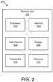
- the remote unit 102 may have any suitable number of transmitters 210 and receivers 212.
- the transmitter 210 and the receiver 212 may be any suitable type of transmitters and receivers.
- the transmitter 210 and the receiver 212 may be part of a transceiver.
- multiple TCI state groups may be configured for a UE by a network entity (e.g., gNB) via transmission to the UE.
- a TCI state group (“TSG”) may include up to 'N' TCI states.
- the gNB may configure multiple DL TX beam combinations (e.g., TSGs) based on the UE's CSI reporting and/or the gNB's knowledge about DL TX beam patterns and TRP deployment.
- the gNB may dynamically indicate up to 'M' TSGs via a TCI codepoint of a TCI field in DCI. Further, the TCI codepoint may map to one or more TSGs (e.g., up to 'M' TSGs).
- a TSG may have a single TCI state, and a number of TCI states in each configured TSG may be different.
- a UE may receive multiple DMRS antenna port indications (e.g., up to 'N' indications) in DCI.
- Each DMRS antenna port indication of the multiple DMRS antenna port indications may be applicable to one or more TSGs with a particular number of TCI states.
- two DMRS antenna port indications (e.g., one for TSGs with a single TCI state and another for TSGs with two TCI states) may be signaled in DCI by a gNB.
- TCI states within a TSG may correspond to spatial beams for different TRPs. In certain embodiments, TCI states within a TSG j may correspond to spatial beams associated with TRP j.
- an enhanced TCI state group activation and/or deactivation for UE-specific PDSCH MAC CE may be identified by a MAC protocol data unit ("PDU") subheader with a logical channel identifier ("LCID").
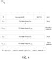
- the MAC CE may have a variable size including the following fields: 1) Serving Cell ID: this field indicates the identity of the serving cell for which the MAC CE applies - the length of this field is 5 bits; 2) bandwidth part (“BWP") ID: this field indicates a DL BWP for which the MAC CE applies as the codepoint of the DCI bandwidth part indicator field - the length of the BWP ID field is 2 bits; 3) Ci,j: this field indicates whether an octet containing TCI state group IDi,j+1 is present - if this field is set to "1", the octet containing TCI state group IDi,j+1 is present - if this field is set to "0", the octet containing TCI state group IDi,j+1
- the first TCI codepoint with TCI state group ID0,1, ..., TCI state group ID0,J(0) shall be mapped to the codepoint value 0
- the second TCI codepoint with TCI state group ID1,1, ..., TCI state ID1,J(1) shall be mapped to the codepoint value 1 and so on, where J(i) denotes the number of TCI state groups for the ith codepoint in the DCI transmission configuration indication field - the TCI state group IDi,2, ...
- TCI state group IDi,J(i) are optional based on the indication of the Ci,1, ..., Ci,J(i)-1 field - the maximum number of activated TCI codepoint is 8 and the maximum number of TCI state groups mapped to a TCI codepoint is Jmax, where Jmax is configured by radio resource control ("RRC") or predefined; and 5) R: reserved bit, set to "0".
- RRC radio resource control
- Figure 4 is a diagram 400 illustrating one embodiment of the enhanced TCI state group activation/deactivation for a UE-specific PDSCH MAC CE.
- up to 'N' TCI states may be signaled by a gNB to a UE by a single index of a TCI codepoint in DCI and 'M-1' consecutive indices next to the signaled index of the activated TCI table may be implied as assigned and/or indicated to the UE.
- index n is signaled to the UE via the TCI codepoint in DCI
- indices n+1, n+2..., n+M-1 may be implied as indicated to the UE (e.g., TCI states corresponding to TCI codepoints n, n+1, n+2..., n+M-1 may be indicated to the UE, or if TCI state j indicated via the TCI codepoint in DCI - TCI states j+1, j+2, ...j+M-1 may be implicitly indicated to the UE).
- a value of M may be explicitly configured or indicated by a gNB to a UE such that an n+M-1 index is less than or equal to a highest index of a TCI table.
- a value of M may be inferred from a number of transmission occasions that is separately configured or indicated by a gNB to a UE.
- a value of M (e.g., Mi) may be configured for each TCI codepoint i.
- up to 'N' TCI states may be signaled by a gNB to a UE by a single index of a TCI codepoint in DCI and 'M-1' consecutive indices next to the signaled index of the activated TCI table may be implied as assigned and/or indicated to the UE.
- index n is signaled to the UE via the TCI codepoint in DCI
- 'M RepNumR16' TSGs and 'N>1' DM-RS CDM groups (e.g., TCI states within each TSG) are indicated to the UE, the UE may expect to receive the same transport block ("TB") with 'N' transmission occasions within one slot and 'N x M' transmissions occasions across 'M' slots.
- TB transport block
- Each TSG may be associated to each slot in a sequential manner and each of the N TCI states within a TSG may be associated to transmission occasions within a slot in a sequential manner.
- 'N' TCI states within a TSG may correspond to a single transmission occasion (e.g., with 'FDMSchemeA') within a slot, but with 'N' non-overlapping frequency domain resources associated with TCI states within TSG 'm', with the 'N' non-overlapping frequency domain resources received on different receive beams and/or panels and transmitted by N different beams of the same TRP or from different TRPs.
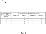
- the redundancy version to be applied to the transmission occasion in slot 'n' may be derived according to an indicated RV sequence RVID in DCI and Figure 5 .
- 'N' is equal to the number of TSGs. Sequential or cyclic mapping may be used if a number of TCI states within a TSG is less than the number of slots.
- the first set of TCI states associated with downlink transmissions and the second TCI states associated with uplink transmissions are indicated by a two separate TCI codepoints.
- an antenna port may be defined such that a channel over which a symbol on the antenna port is conveyed may be inferred from the channel over which another symbol on the same antenna port is conveyed.
- two antenna ports are said to be quasi co-located ("QCL") if large-scale properties of a channel over which a symbol on one antenna port is conveyed may be inferred from the channel over which a symbol on another antenna port is conveyed.
- Large-scale properties may include one or more of delay spread, Doppler spread, Doppler shift, average gain, average delay, and/or spatial receive ("RX") parameters.
- Two antenna ports may be quasi co-located with respect to a subset of the large-scale properties and different subset of large-scale properties may be indicated by a QCL Type.
- a qcl-Type may take one of the following values: 1) 'QCL-TypeA': ⁇ Doppler shift, Doppler spread, average delay, delay spread ⁇ ; 2) 'QCL-TypeB': ⁇ Doppler shift, Doppler spread ⁇ ; 3) 'QCL-TypeC': ⁇ Doppler shift, average delay ⁇ ; and 4) 'QCL-TypeD': ⁇ Spatial Rx parameter ⁇ .
- spatial RX parameters may include one or more of: angle of arrival (“AoA”), dominant AoA, average AoA, angular spread, power angular spectrum (“PAS”) of AoA, average angle of departure (“AoD”), PAS of AoD, transmit and/or receive channel correlation, transmit and/or receive beamforming, and/or spatial channel correlation.
- AoA angle of arrival
- PAS power angular spectrum
- AoD average angle of departure
- PAS of AoD transmit and/or receive channel correlation
- transmit and/or receive beamforming and/or spatial channel correlation.
- an "antenna port” may be a logical port that may correspond to a beam (e.g., resulting from beamforming) or may correspond to a physical antenna on a device.
- a physical antenna may map directly to a single antenna port in which an antenna port corresponds to an actual physical antenna.
- a set of physical antennas, a subset of physical antennas, an antenna set, an antenna array, or an antenna sub-array may be mapped to one or more antenna ports after applying complex weights and/or a cyclic delay to the signal on each physical antenna.
- the physical antenna set may have antennas from a single module or panel or from multiple modules or panels.
- the weights may be fixed as in an antenna virtualization scheme, such as cyclic delay diversity ("CDD").
- CDD cyclic delay diversity
- a UE antenna panel may be a physical or logical antenna array including a set of antenna elements or antenna ports that share a common or a significant portion of a radio frequency (“RF") chain (e.g., in-phase and/or quadrature (“I/Q") modulator, analog to digital (“A/D”) converter, local oscillator, phase shift network).
- RF radio frequency
- the UE antenna panel or UE panel may be a logical entity with physical UE antennas mapped to the logical entity. The mapping of physical UE antennas to the logical entity may be up to UE implementation.
- Communicating (e.g., receiving or transmitting) on at least a subset of antenna elements or antenna ports active for radiating energy (e.g., active elements) of an antenna panel may require biasing or powering on of an RF chain which results in current drain or power consumption in a UE associated with the antenna panel (e.g., including power amplifier and/or low noise amplifier (“LNA”) power consumption associated with the antenna elements or antenna ports).
- LNA low noise amplifier
- an antenna element that is active for radiating energy may be coupled to a transmitter to transmit radio frequency energy or to a receiver to receive radio frequency energy, either simultaneously or sequentially, or may be coupled to a transceiver in general, for performing its intended functionality. Communicating on the active elements of an antenna panel enables generation of radiation patterns or beams.
- a UE may report its UE capability with respect to the "UE panel" to the gNB or network.
- the UE capability may include at least the number of "UE panels.”
- a UE may support UL transmission from one beam within a panel. With multiple panels, more than one beam (e.g., one beam per panel) may be used for UL transmission. In another embodiment, more than one beam per panel may be supported and/or used for UL transmission.
- a transmission configuration indicator (“TCI") state associated with a target transmission may indicate a quasi-collocation relationship between a target transmission (e.g., target RS of demodulation reference signal (“DM-RS”) ports of the target transmission during a transmission occasion) and source reference signals (e.g., synchronization signal block (“SSB”), channel state information reference signal (“CSI-RS”), and/or sounding reference signal (“SRS”)) with respect to quasi co-location type parameters indicated in a corresponding TCI state.
- a UE may receive a configuration of multiple transmission configuration indicator states for a serving cell for transmissions on the serving cell.
- spatial relation information associated with a target transmission may indicate a spatial setting between a target transmission and a reference RS (e.g., SSB, CSI-RS, and/or SRS).
- a UE may transmit a target transmission with the same spatial domain filter used for receiving a reference RS (e.g., DL RS such as SSB and/or CSI-RS).
- a UE may transmit a target transmission with the same spatial domain transmission filter used for the transmission of a RS (e.g., UL RS such as SRS).
- a UE may receive a configuration of multiple spatial relation information configurations for a serving cell for transmissions on a serving cell.
- Figure 7 is a flow chart diagram illustrating one embodiment of a method 700 for transmission configuration indicator states association to transmission occasions.
- the method 700 is performed by an apparatus, such as the remote unit 102.
- the method 700 may be performed by a processor executing program code, for example, a microcontroller, a microprocessor, a CPU, a GPU, an auxiliary processing unit, a FPGA, or the like.
- the method 700 includes receiving 702, from at least one network device, first information indicating a first set of transmission configuration indicator states. In various embodiments, the method 700 includes receiving 704, from the at least one network device, second information indicating a second set of transmission configuration indicator states. In some embodiments, the method 700 includes determining 706 an association between the first set of transmission configuration indicator states and a first set of transmission occasions. In various embodiments, the method 700 includes determining 708 an association between the second set of transmission configuration indicator states and a second set of transmission occasions.
- the first set of transmission configuration indicator states comprises a downlink transmission configuration indicator
- the second set of transmission configuration indicator states comprises an uplink transmission configuration indicator
- the first set of transmission occasions is associated with downlink reception
- the second set of transmission occasions is associated with uplink transmission
- the first set of transmission configuration indicator states and the second set of transmission configuration indicator states are indicated by a codepoint in downlink control information
- the first set of transmission configuration indicator states contains N transmission configuration indicator states
- the second set of transmission configuration indicator states contain the M transmission configuration indicator states indicated by a single transmission configuration indicator codepoint.
- a number of the plurality of consecutive neighboring indices is implied as a remaining number of indices above the index or a remaining number of indices below the index.
- multiple transmission configuration indicator states within a transmission configuration indicator set indicated by a transmission configuration indicator codepoint in downlink control information are associated with a single demodulation reference signal port.
- transmission occasions within a slot are in a spatial domain, a frequency domain, a time domain, or some combination thereof.
- the first set of transmission configuration indicator states is associated with a first transmission and reception point and the second set of transmission configuration indicator states is associated with a second transmission and reception point.
- the first set of transmission configuration indicator states and the second set of transmission configuration indicator states are indicated by a codepoint in downlink control information, and a number of transmission configuration indicator states is variable across a plurality of sets of transmission configuration indicator states.
- the first set of transmission configuration indicator states and the second set of transmission configuration indicator states are indicated by a codepoint in downlink control information, the codepoint points to an index of an activated transmission configuration indicator table with at least one transmission configuration indicator state, and a plurality of consecutive neighboring indices of the index are implied as being indicated.
- a number of the plurality of consecutive neighboring indices is explicitly indicated or configured in an increasing order of indexing with respect to the index or a decreasing order of indexing with respect to the index.
- a number of the plurality of consecutive neighboring indices is implied as a remaining number of indices above the index or a remaining number of indices below the index.
- multiple transmission configuration indicator states within a transmission configuration indicator set indicated by a transmission configuration indicator codepoint in downlink control information are associated with a single demodulation reference signal port.
- transmission occasions within a slot are in a spatial domain, a frequency domain, a time domain, or some combination thereof.
- an apparatus comprises: a receiver that: receives, from at least one network device, first information indicating a first set of transmission configuration indicator states; and receives, from the at least one network device, second information indicating a second set of transmission configuration indicator states; and a processor that: determines an association between the first set of transmission configuration indicator states and a first set of transmission occasions; and determines an association between the second set of transmission configuration indicator states and a second set of transmission occasions.
- the first set of transmission configuration indicator states comprises a downlink transmission configuration indicator
- the second set of transmission configuration indicator states comprises an uplink transmission configuration indicator
- the first set of transmission occasions is associated with downlink reception
- the second set of transmission occasions is associated with uplink transmission
- the first set of transmission configuration indicator states and the second set of transmission configuration indicator states are indicated by a codepoint in downlink control information
- the first set of transmission configuration indicator states contains N transmission configuration indicator states
- the second set of transmission configuration indicator states contain the M transmission configuration indicator states indicated by a single transmission configuration indicator codepoint.
- the first set of transmission configuration indicator states is associated with a first transmission and reception point and the second set of transmission configuration indicator states is associated with a second transmission and reception point.
- the first set of transmission configuration indicator states and the second set of transmission configuration indicator states are indicated by a codepoint in downlink control information, and a number of transmission configuration indicator states is variable across a plurality of sets of transmission configuration indicator states.
- the first set of transmission configuration indicator states and the second set of transmission configuration indicator states are indicated by a codepoint in downlink control information, the codepoint points to an index of an activated transmission configuration indicator table with at least one transmission configuration indicator state, and a plurality of consecutive neighboring indices of the index are implied as being indicated.
- a number of the plurality of consecutive neighboring indices is explicitly indicated or configured in an increasing order of indexing with respect to the index or a decreasing order of indexing with respect to the index.
- a number of the plurality of consecutive neighboring indices is implied as a remaining number of indices above the index or a remaining number of indices below the index.
- multiple transmission configuration indicator states within a transmission configuration indicator set indicated by a transmission configuration indicator codepoint in downlink control information are associated with a single demodulation reference signal port.
- transmission occasions within a slot are in a spatial domain, a frequency domain, a time domain, or some combination thereof.
Landscapes
- Engineering & Computer Science (AREA)
- Signal Processing (AREA)
- Computer Networks & Wireless Communication (AREA)
- Mobile Radio Communication Systems (AREA)
- Telephonic Communication Services (AREA)
Claims (14)
- Verfahren, das durch eine Einrichtung durchgeführt wird, umfassend:Empfangen, von mindestens einer Netzwerkvorrichtung, von ersten Informationen, die einen ersten Satz von mehreren Übertragungskonfigurationsanzeigezuständen anzeigen;Empfangen, von der mindestens einen Netzwerkvorrichtung, von zweiten Informationen, die einen zweiten Satz von mehreren Übertragungskonfigurationsanzeigezuständen anzeigen;Bestimmen einer Zuordnung zwischen dem ersten Satz von Übertragungskonfigurationsanzeigezuständen und einem ersten Satz von Übertragungsgelegenheiten; undBestimmen einer Verbindung zwischen dem zweiten Satz von Übertragungskonfigurationsanzeigezuständen und einem zweiten Satz von Übertragungsgelegenheiten,wobei der erste Satz von Übertragungskonfigurationsanzeigezuständen und der zweite Satz von Übertragungskonfigurationsanzeigezuständen durch einen Codepunkt in Downlink-Steuerinformationen angezeigt werden, der Codepunkt auf einen Index einer aktivierten Übertragungskonfigurationsanzeigetabelle mit mindestens einem Übertragungskonfigurationsanzeigezustand zeigt, unddadurch gekennzeichnet, dass eine Vielzahl von aufeinanderfolgenden benachbarten Indizes des Index implizit angezeigt wird.
- Verfahren nach Anspruch 1, wobei der erste Satz von Übertragungskonfigurationsanzeigezuständen einem ersten Übertragungs- und Empfangspunkt zugeordnet ist und der zweite Satz von Übertragungskonfigurationsanzeigezuständen einem zweiten Übertragungs- und Empfangspunkt zugeordnet ist.
- Verfahren nach Anspruch 1,
eine Anzahl von Übertragungskonfigurationsanzeigezuständen über eine Vielzahl von Sätzen von Übertragungskonfigurationsanzeigezuständen variabel ist. - Verfahren nach Anspruch 1, wobei eine Anzahl der Vielzahl von aufeinanderfolgenden benachbarten Indizes explizit angezeigt oder in einer aufsteigenden Indizierungsreihenfolge in Bezug auf den Index oder einer absteigenden Indizierungsreihenfolge in Bezug auf den Index konfiguriert wird.
- Verfahren nach Anspruch 1, wobei eine Anzahl der Vielzahl von aufeinanderfolgenden benachbarten Indizes als eine verbleibende Anzahl von Indizes über dem Index oder eine verbleibende Anzahl von Indizes unter dem Index impliziert wird.
- Verfahren nach Anspruch 1, wobei mehrere Übertragungskonfigurationsanzeigezustände innerhalb eines Übertragungskonfigurationsanzeigesatzes, der durch einen Übertragungskonfigurationsanzeigecodepunkt in Downlink-Steuerinformationen angezeigt wird, einem einzigen Demodulationsreferenzsignalanschluss zugeordnet sind.
- Verfahren nach Anspruch 1, wobei Übertragungsgelegenheiten innerhalb eines Schlitzes in einem Ortsbereich, einem Frequenzbereich, einem Zeitbereich oder einer Kombination davon liegen.
- Vorrichtung, umfassend:
einen Empfänger, der konfiguriert ist zum:Empfangen, von mindestens einer Netzwerkvorrichtung, von ersten Informationen, die einen ersten Satz von mehreren Übertragungskonfigurationsanzeigezuständen anzeigen; undEmpfangen, von der mindestens einen Netzwerkvorrichtung, von zweiten Informationen, die einen zweiten Satz von mehreren Übertragungskonfigurationsanzeigezuständen anzeigen; undeinen Prozessor, der konfiguriert ist zum:dadurch gekennzeichnet, dass eine Vielzahl von aufeinanderfolgenden benachbarten Indizes des Index implizit angezeigt wird.Bestimmen einer Zuordnung zwischen dem ersten Satz von Übertragungskonfigurationsanzeigezuständen und einem ersten Satz von Übertragungsgelegenheiten; undBestimmen einer Zuordnung zwischen dem zweiten Satz von Übertragungskonfigurationsanzeigezuständen und einem zweiten Satz von Übertragungsgelegenheiten,wobei der erste Satz von Übertragungskonfigurationsanzeigezuständen und der zweite Satz von Übertragungskonfigurationsanzeigezuständen durch einen Codepunkt in Downlink-Steuerinformationen angezeigt werden, der Codepunkt auf einen Index einer aktivierten Übertragungskonfigurationsanzeigetabelle mit mindestens einem Übertragungskonfigurationsanzeigezustand zeigt, und - Einrichtung nach Anspruch 8, wobei der erste Satz von Übertragungskonfigurationsanzeigezuständen einem ersten Übertragungs- und Empfangspunkt zugeordnet ist und der zweite Satz von Übertragungskonfigurationsanzeigezuständen einem zweiten Übertragungs- und Empfangspunkt zugeordnet ist.
- Einrichtung nach Anspruch 8,
eine Anzahl von Übertragungskonfigurationsanzeigezuständen über eine Vielzahl von Sätzen von Übertragungskonfigurationsanzeigezuständen variabel ist. - Einrichtung nach Anspruch 8, wobei eine Anzahl der Vielzahl von aufeinanderfolgenden benachbarten Indizes explizit angezeigt oder in einer aufsteigenden Indizierungsreihenfolge in Bezug auf den Index oder einer absteigenden Indizierungsreihenfolge in Bezug auf den Index konfiguriert ist.
- Einrichtung nach Anspruch 8, wobei eine Anzahl der Vielzahl von aufeinanderfolgenden benachbarten Indizes als eine verbleibende Anzahl von Indizes über dem Index oder als eine verbleibende Anzahl von Indizes unter dem Index impliziert ist.
- Einrichtung nach Anspruch 8, wobei mehrere Übertragungskonfigurationsanzeigezustände innerhalb eines Übertragungskonfigurationsanzeigesatzes, der durch einen Übertragungskonfigurationsanzeigecodepunkt in Downlink-Steuerinformationen angezeigt wird, einem einzigen Demodulationsreferenzsignalanschluss zugeordnet sind.
- Einrichtung nach Anspruch 8, wobei Übertragungsgelegenheiten innerhalb eines Schlitzes in einem Ortsbereich, einem Frequenzbereich, einem Zeitbereich oder einer Kombination davon liegen.
Applications Claiming Priority (2)
| Application Number | Priority Date | Filing Date | Title |
|---|---|---|---|
| US202063002827P | 2020-03-31 | 2020-03-31 | |
| PCT/IB2021/052668 WO2021198933A1 (en) | 2020-03-31 | 2021-03-30 | Transmission configuration indicator state association |
Publications (3)
| Publication Number | Publication Date |
|---|---|
| EP4128637A1 EP4128637A1 (de) | 2023-02-08 |
| EP4128637B1 true EP4128637B1 (de) | 2025-06-25 |
| EP4128637C0 EP4128637C0 (de) | 2025-06-25 |
Family
ID=75581543
Family Applications (1)
| Application Number | Title | Priority Date | Filing Date |
|---|---|---|---|
| EP21719970.2A Active EP4128637B1 (de) | 2020-03-31 | 2021-03-30 | Zustandsassoziation eines übertragungskonfigurationsindikators |
Country Status (6)
| Country | Link |
|---|---|
| US (1) | US20230144547A1 (de) |
| EP (1) | EP4128637B1 (de) |
| KR (1) | KR20220161325A (de) |
| CN (1) | CN115349238B (de) |
| MX (1) | MX2022012335A (de) |
| WO (1) | WO2021198933A1 (de) |
Families Citing this family (6)
| Publication number | Priority date | Publication date | Assignee | Title |
|---|---|---|---|---|
| EP3955665A4 (de) * | 2019-04-10 | 2022-11-16 | Beijing Xiaomi Mobile Software Co., Ltd. | Ressourcenanzeigeverfahren und -vorrichtung |
| US11705954B2 (en) * | 2021-03-08 | 2023-07-18 | Qualcomm Incorporated | Transmission configuration indicator state group indication |
| US20240235797A1 (en) * | 2021-10-22 | 2024-07-11 | Intel Corporation | Transmission configuration indicator (tci) chain enhancements for new radio systems |
| US20240413950A1 (en) * | 2022-01-31 | 2024-12-12 | Beammwave Ab | Method of Configuring First and Second Sets of Active Transceivers, a Computer Program Product, a Processing Unit, and Wireless Devices Therefor |
| US20250220669A1 (en) * | 2022-04-27 | 2025-07-03 | Lg Electronics Inc. | Method and apparatus for uplink transmission and reception in wireless communication system |
| US12471085B2 (en) * | 2023-01-26 | 2025-11-11 | Qualcomm Incorporated | Separate DL-UL beam indication for separate DL-UL TCI state |
Family Cites Families (11)
| Publication number | Priority date | Publication date | Assignee | Title |
|---|---|---|---|---|
| CN109587793B (zh) * | 2017-09-29 | 2021-08-31 | 维沃移动通信有限公司 | Tci状态更新方法、基站及终端 |
| US11026253B2 (en) * | 2018-04-26 | 2021-06-01 | Qualcomm Incorporated | Mapping a physical downlink control channel (PDCCH) across multiple transmission configuration indication (TCI) states |
| US11324028B2 (en) * | 2018-06-22 | 2022-05-03 | Qualcomm Incorporated | Transmission configuration indicator pattern list for shared channel transmission |
| US12075431B2 (en) * | 2018-12-11 | 2024-08-27 | Lg Electronics Inc. | Method for operating terminal and base station in wireless communication system, and device supporting same |
| EP3897057B1 (de) * | 2019-02-15 | 2023-07-12 | Huawei Technologies Co., Ltd. | Informationsangabeverfahren und -vorrichtung |
| US12408174B2 (en) * | 2019-09-15 | 2025-09-02 | Qualcomm Incorporated | Transmission configuration indicator state activation techniques for carrier aggregation |
| US12219557B2 (en) * | 2019-11-05 | 2025-02-04 | Comcast Cable Communications, Llc | Wireless communications for scheduling transmissions |
| CN110856258B (zh) * | 2019-11-08 | 2022-02-22 | 中国信息通信研究院 | 一种多点发送波束指示方法和设备 |
| CN111901083B (zh) * | 2020-01-17 | 2025-05-06 | 中兴通讯股份有限公司 | 一种准共址信息获取方法、通信节点及存储介质 |
| WO2021157938A1 (ko) * | 2020-02-07 | 2021-08-12 | 엘지전자 주식회사 | 무선 통신 시스템에서 하향링크 제어 정보 송수신 방법 및 장치 |
| US12256407B2 (en) * | 2020-02-13 | 2025-03-18 | Ipla Holdings Inc. | Reliability enhancement for PDCCH |
-
2021
- 2021-03-30 KR KR1020227033609A patent/KR20220161325A/ko active Pending
- 2021-03-30 EP EP21719970.2A patent/EP4128637B1/de active Active
- 2021-03-30 WO PCT/IB2021/052668 patent/WO2021198933A1/en not_active Ceased
- 2021-03-30 CN CN202180023196.4A patent/CN115349238B/zh active Active
- 2021-03-30 MX MX2022012335A patent/MX2022012335A/es unknown
- 2021-03-30 US US17/916,508 patent/US20230144547A1/en active Pending
Also Published As
| Publication number | Publication date |
|---|---|
| CN115349238A (zh) | 2022-11-15 |
| US20230144547A1 (en) | 2023-05-11 |
| EP4128637A1 (de) | 2023-02-08 |
| MX2022012335A (es) | 2023-01-05 |
| EP4128637C0 (de) | 2025-06-25 |
| CN115349238B (zh) | 2025-06-24 |
| WO2021198933A1 (en) | 2021-10-07 |
| KR20220161325A (ko) | 2022-12-06 |
Similar Documents
| Publication | Publication Date | Title |
|---|---|---|
| US11799613B2 (en) | Channel state information report configuration | |
| EP4128637B1 (de) | Zustandsassoziation eines übertragungskonfigurationsindikators | |
| US12047859B2 (en) | Configuring repeater-assisted communication | |
| EP4218152A1 (de) | Meldung von kanalstatusinformationen für hochgeschwindigkeitsvorrichtungen | |
| US20250047454A1 (en) | Configuring a bandwidth part for uplink and downlink | |
| US20240236987A1 (en) | Configuring csi reporting for multi-trp transmission | |
| WO2023031709A1 (en) | Configuring a codebook corresponding to transmit precoding matrix information | |
| US20240333353A1 (en) | Channel state information report configuration | |
| WO2023135576A1 (en) | Communicating based on an ssb burst configuration | |
| US20230328841A1 (en) | Configuring a wakeup signal | |
| EP4423918A1 (de) | Konfiguration von kanalstatusinformationsberichten | |
| US20240056237A1 (en) | Configuring a channel state information report for full-duplex communication | |
| US20230353209A1 (en) | Reporting channel state information based on a transmission hypothesis | |
| US20240137167A1 (en) | Configuring a channel state information report | |
| US20230361831A1 (en) | Determining channel state information reference signals |
Legal Events
| Date | Code | Title | Description |
|---|---|---|---|
| STAA | Information on the status of an ep patent application or granted ep patent |
Free format text: STATUS: UNKNOWN |
|
| STAA | Information on the status of an ep patent application or granted ep patent |
Free format text: STATUS: THE INTERNATIONAL PUBLICATION HAS BEEN MADE |
|
| PUAI | Public reference made under article 153(3) epc to a published international application that has entered the european phase |
Free format text: ORIGINAL CODE: 0009012 |
|
| STAA | Information on the status of an ep patent application or granted ep patent |
Free format text: STATUS: REQUEST FOR EXAMINATION WAS MADE |
|
| 17P | Request for examination filed |
Effective date: 20220824 |
|
| AK | Designated contracting states |
Kind code of ref document: A1 Designated state(s): AL AT BE BG CH CY CZ DE DK EE ES FI FR GB GR HR HU IE IS IT LI LT LU LV MC MK MT NL NO PL PT RO RS SE SI SK SM TR |
|
| DAV | Request for validation of the european patent (deleted) | ||
| DAX | Request for extension of the european patent (deleted) | ||
| GRAP | Despatch of communication of intention to grant a patent |
Free format text: ORIGINAL CODE: EPIDOSNIGR1 |
|
| STAA | Information on the status of an ep patent application or granted ep patent |
Free format text: STATUS: GRANT OF PATENT IS INTENDED |
|
| INTG | Intention to grant announced |
Effective date: 20250130 |
|
| GRAS | Grant fee paid |
Free format text: ORIGINAL CODE: EPIDOSNIGR3 |
|
| GRAA | (expected) grant |
Free format text: ORIGINAL CODE: 0009210 |
|
| STAA | Information on the status of an ep patent application or granted ep patent |
Free format text: STATUS: THE PATENT HAS BEEN GRANTED |
|
| AK | Designated contracting states |
Kind code of ref document: B1 Designated state(s): AL AT BE BG CH CY CZ DE DK EE ES FI FR GB GR HR HU IE IS IT LI LT LU LV MC MK MT NL NO PL PT RO RS SE SI SK SM TR |
|
| REG | Reference to a national code |
Ref country code: GB Ref legal event code: FG4D |
|
| REG | Reference to a national code |
Ref country code: CH Ref legal event code: EP |
|
| REG | Reference to a national code |
Ref country code: CH Ref legal event code: EP |
|
| REG | Reference to a national code |
Ref country code: IE Ref legal event code: FG4D |
|
| REG | Reference to a national code |
Ref country code: DE Ref legal event code: R096 Ref document number: 602021032837 Country of ref document: DE |
|
| U01 | Request for unitary effect filed |
Effective date: 20250715 |
|
| U07 | Unitary effect registered |
Designated state(s): AT BE BG DE DK EE FI FR IT LT LU LV MT NL PT RO SE SI Effective date: 20250725 |
|
| PG25 | Lapsed in a contracting state [announced via postgrant information from national office to epo] |
Ref country code: NO Free format text: LAPSE BECAUSE OF FAILURE TO SUBMIT A TRANSLATION OF THE DESCRIPTION OR TO PAY THE FEE WITHIN THE PRESCRIBED TIME-LIMIT Effective date: 20250925 Ref country code: GR Free format text: LAPSE BECAUSE OF FAILURE TO SUBMIT A TRANSLATION OF THE DESCRIPTION OR TO PAY THE FEE WITHIN THE PRESCRIBED TIME-LIMIT Effective date: 20250926 |
|
| PG25 | Lapsed in a contracting state [announced via postgrant information from national office to epo] |
Ref country code: HR Free format text: LAPSE BECAUSE OF FAILURE TO SUBMIT A TRANSLATION OF THE DESCRIPTION OR TO PAY THE FEE WITHIN THE PRESCRIBED TIME-LIMIT Effective date: 20250625 |
|
| PG25 | Lapsed in a contracting state [announced via postgrant information from national office to epo] |
Ref country code: RS Free format text: LAPSE BECAUSE OF FAILURE TO SUBMIT A TRANSLATION OF THE DESCRIPTION OR TO PAY THE FEE WITHIN THE PRESCRIBED TIME-LIMIT Effective date: 20250925 |
|
| PG25 | Lapsed in a contracting state [announced via postgrant information from national office to epo] |
Ref country code: IS Free format text: LAPSE BECAUSE OF FAILURE TO SUBMIT A TRANSLATION OF THE DESCRIPTION OR TO PAY THE FEE WITHIN THE PRESCRIBED TIME-LIMIT Effective date: 20251025 |
|
| PG25 | Lapsed in a contracting state [announced via postgrant information from national office to epo] |
Ref country code: SM Free format text: LAPSE BECAUSE OF FAILURE TO SUBMIT A TRANSLATION OF THE DESCRIPTION OR TO PAY THE FEE WITHIN THE PRESCRIBED TIME-LIMIT Effective date: 20250625 |
|
| PG25 | Lapsed in a contracting state [announced via postgrant information from national office to epo] |
Ref country code: CZ Free format text: LAPSE BECAUSE OF FAILURE TO SUBMIT A TRANSLATION OF THE DESCRIPTION OR TO PAY THE FEE WITHIN THE PRESCRIBED TIME-LIMIT Effective date: 20250625 |
|
| PG25 | Lapsed in a contracting state [announced via postgrant information from national office to epo] |
Ref country code: PL Free format text: LAPSE BECAUSE OF FAILURE TO SUBMIT A TRANSLATION OF THE DESCRIPTION OR TO PAY THE FEE WITHIN THE PRESCRIBED TIME-LIMIT Effective date: 20250625 |
|
| PG25 | Lapsed in a contracting state [announced via postgrant information from national office to epo] |
Ref country code: SK Free format text: LAPSE BECAUSE OF FAILURE TO SUBMIT A TRANSLATION OF THE DESCRIPTION OR TO PAY THE FEE WITHIN THE PRESCRIBED TIME-LIMIT Effective date: 20250625 |
|
| PG25 | Lapsed in a contracting state [announced via postgrant information from national office to epo] |
Ref country code: ES Free format text: LAPSE BECAUSE OF FAILURE TO SUBMIT A TRANSLATION OF THE DESCRIPTION OR TO PAY THE FEE WITHIN THE PRESCRIBED TIME-LIMIT Effective date: 20250625 |
|
| PGFP | Annual fee paid to national office [announced via postgrant information from national office to epo] |
Ref country code: GB Payment date: 20260319 Year of fee payment: 6 |