EP4128583B1 - Récepteur pour système de transmission de lumière, système de transmission de lumière et procédé de fonctionnement d'un système de transmission de lumière - Google Patents
Récepteur pour système de transmission de lumière, système de transmission de lumière et procédé de fonctionnement d'un système de transmission de lumière Download PDFInfo
- Publication number
- EP4128583B1 EP4128583B1 EP21708623.0A EP21708623A EP4128583B1 EP 4128583 B1 EP4128583 B1 EP 4128583B1 EP 21708623 A EP21708623 A EP 21708623A EP 4128583 B1 EP4128583 B1 EP 4128583B1
- Authority
- EP
- European Patent Office
- Prior art keywords
- light
- regions
- receiver
- profiled
- transverse direction
- Prior art date
- Legal status (The legal status is an assumption and is not a legal conclusion. Google has not performed a legal analysis and makes no representation as to the accuracy of the status listed.)
- Active
Links
Images

Classifications
-
- H—ELECTRICITY
- H04—ELECTRIC COMMUNICATION TECHNIQUE
- H04N—PICTORIAL COMMUNICATION, e.g. TELEVISION
- H04N23/00—Cameras or camera modules comprising electronic image sensors; Control thereof
- H04N23/50—Constructional details
- H04N23/55—Optical parts specially adapted for electronic image sensors; Mounting thereof
-
- H—ELECTRICITY
- H04—ELECTRIC COMMUNICATION TECHNIQUE
- H04B—TRANSMISSION
- H04B10/00—Transmission systems employing electromagnetic waves other than radio-waves, e.g. infrared, visible or ultraviolet light, or employing corpuscular radiation, e.g. quantum communication
- H04B10/11—Arrangements specific to free-space transmission, i.e. transmission through air or vacuum
- H04B10/114—Indoor or close-range type systems
- H04B10/116—Visible light communication
-
- G—PHYSICS
- G06—COMPUTING OR CALCULATING; COUNTING
- G06V—IMAGE OR VIDEO RECOGNITION OR UNDERSTANDING
- G06V10/00—Arrangements for image or video recognition or understanding
- G06V10/10—Image acquisition
- G06V10/12—Details of acquisition arrangements; Constructional details thereof
- G06V10/14—Optical characteristics of the device performing the acquisition or on the illumination arrangements
- G06V10/141—Control of illumination
-
- H—ELECTRICITY
- H04—ELECTRIC COMMUNICATION TECHNIQUE
- H04N—PICTORIAL COMMUNICATION, e.g. TELEVISION
- H04N25/00—Circuitry of solid-state image sensors [SSIS]; Control thereof
- H04N25/70—SSIS architectures; Circuits associated therewith
- H04N25/71—Charge-coupled device [CCD] sensors; Charge-transfer registers specially adapted for CCD sensors
- H04N25/74—Circuitry for scanning or addressing the pixel array
Definitions
- the invention relates to a receiver for a system for light transmission, comprising a camera which has an image sensor, wherein a light-sensitive surface of the image sensor comprises several rows of light-sensitive elements, wherein the image sensor is designed such that the light-sensitive surface of the image sensor is scanned row by row or column by column, and an attachment element which is arranged such that light incident on the light-sensitive surface of the image sensor first passes through the attachment element.
- the invention also relates to a system for light transmission, comprising a receiver according to the invention and a transmitter.
- the invention further relates to a method for operating a system for light transmission according to the invention.
- a system and a method for data transmission using visible light are known from the article "Using a CMOS Camera Sensor for Visible Light Communication", Danakis et al., 978-1-4673-4941-3, IEEE.
- a smartphone camera serves as a receiver for visible light.
- the camera includes a CMOS image sensor whose light-sensitive surface is scanned line by line.
- a light source in the form of an LED serves as the transmitter, emitting modulated light.
- the system has a receiver with an image sensor, the light-sensitive surface of which is scanned line by line, and a transmitter with a controllable light source that emits modulated light.
- the receiver has a lenticular film or a cylindrical lens array that is arranged between a lens of the receiver and the transmitter.
- An image projected onto the light-sensitive surface of the image sensor is blurred.
- An optical system with an optical antenna arrangement that provides illumination for an object is known.
- a second optical antenna element captures a portion of the light reflected from the object.
- the optical antenna arrangement can selectively illuminate spatial locations, and the receiving optical antenna arrangement can selectively receive light.
- the camera includes a lens that is removable from a light path between an opening and a sensor.
- the lens sheet comprises projections coated with a light-absorbing material.
- the invention is based on the object of further developing a receiver for a system for light transmission, a corresponding system and a method for operating the system.
- the object is achieved by a receiver for a light transmission system with the features specified in claim 1.
- Advantageous embodiments and further developments are the subject of the subclaims.
- the object is also achieved by a light transmission system with the features specified in claim 10.
- Advantageous embodiments and further developments are the subject of the subclaims.
- the object is also achieved by a method for operating a light transmission system with the features specified in claim 12.
- Advantageous embodiments and further developments are the subject of the subclaims.
- a receiver according to the invention for a system for light transmission comprises a camera which has an image sensor.
- a light-sensitive surface of the image sensor comprises several rows of light-sensitive elements.
- the image sensor is designed in such a way that the light-sensitive surface of the image sensor is scanned row by row or column by column.
- the receiver also comprises an attachment element.
- the attachment element is arranged in such a way that that light incident on the light-sensitive surface of the image sensor first passes through the attachment element.
- the attachment element comprises a plurality of strip-shaped profiled regions and a plurality of strip-shaped planar regions.
- the profiled regions and the planar regions are arranged alternately in a transverse direction.
- the profiled regions have a constant cross-section in a preferred direction which runs at right angles to the transverse direction.
- Light that passes through the profiled areas of the attachment element is refracted relatively strongly and creates a first image on the light-sensitive surface of the image sensor.
- the first image created on the camera's image sensor is therefore a blurred image.
- a light beam originating from a point light source is imaged in the form of a light strip.
- the light strip in question is light and dark in temporal sequence, depending on the modulation.
- the light strip can have light and dark areas, depending on the modulation.
- a data stream can be detected from the light and dark areas of the light strip in question, according to which the light source emits modulated light.
- the second image created on the camera's image sensor is therefore a sharp optical image.
- the receiver's design according to the invention means that a data stream can be detected from the first image at a data transmission rate that is greater than the frame rate of the receiver's camera.
- a sharp optical image can be detected from the second image.
- the receiver according to the invention is therefore advantageously suitable for fast data transmission and also for the simultaneous recording of sharp optical images.
- the attachment element can be manufactured relatively easily and inexpensively.
- the attachment element is designed in the form of a film or in the form of a plate.
- the planar areas have a constant material thickness.
- the film or plate is translucent.
- the profiled areas have depressions and thus a lower material thickness than the planar areas.
- the profiled areas are therefore concave. This ensures that the refraction of an incident light beam is not the same everywhere, but depends on the point of impact.
- the attachment element can be manufactured particularly easily and inexpensively, for example by milling the depressions out of a film or a plate in the preferred direction.
- the profiled areas have elevations and thus a greater material thickness than the planar areas.
- the profiled areas are therefore convex. This ensures that the refraction of an incident light beam is not the same everywhere, but depends on the point of impact.
- the attachment element comprises profiled areas which have depressions and thus a smaller material thickness than the planar areas and profiled areas which have elevations and thus a greater material thickness than the planar areas.
- the profiled regions have an at least approximately semicircular cross-section.
- an extension of one of the planar regions in the transverse direction is greater than an extension of one of the profiled regions in the transverse direction.
- an extension of each of the planar regions in the transverse direction is greater than an extension of each of the profiled regions in the transverse direction.
- the extent of one of the planar regions in the transverse direction is at least twice as large as the extent of one of the profiled regions in the transverse direction. Furthermore, particularly preferably, the extent of one of the planar regions in the transverse direction is at most ten times as large as the extent of one of the profiled Regions in the transverse direction. In particular, the extent of each of the planar regions in the transverse direction is at least twice as large as the extent of each of the profiled regions in the transverse direction. In particular, furthermore, the extent of each of the planar regions in the transverse direction is at most ten times as large as the extent of each of the profiled regions in the transverse direction.
- the receiver further comprises a recording unit.
- the recording unit has a first recording element and a second recording element, which is movable relative to the first recording element.
- the camera is accommodated in the first recording element and the attachment element is accommodated in the second recording element.
- the attachment element is thus movable relative to the camera, for example pivotable or displaceable.
- a system for light transmission according to the invention comprises a receiver according to the invention and a transmitter which has at least one controllable light source.
- the at least one light source of the transmitter emits modulated light in accordance with a predetermined data stream.
- the attachment element of the receiver is arranged between the at least one controllable light source of the transmitter and the camera of the receiver. This ensures that light which strikes the light-sensitive surface of the image sensor of the camera first passes through the attachment element.
- the light-sensitive surface of the image sensor is scanned line by line or column by column.
- a first image which is projected onto the light-sensitive surface by the profiled areas of the attachment element, is processed separately from a second image, which is projected onto the light-sensitive surface by the planar areas of the attachment element.
- the data stream is detected from the first image, according to which the at least one controllable light source of the transmitter emits modulated light.
- the data transmission rate of the data stream is advantageously greater than a frame rate of the camera of the receiver.
- an optical image is detected from the second image.
- the second image is advantageously a sharp optical image.
- different information can be transmitted from the transmitter to the receiver simultaneously using the first image and the second image and can be received by the receiver.
- coordinates can be encoded in the data stream.
- location is then possible.
- a QR code can be scanned, for example.
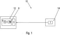
- FIG. 1 shows a schematic representation of a system 10 for light transmission.
- the system 10 for light transmission comprises a transmitter 14, which has a controllable light source 1.
- the light source 1 is, for example, an LED, a ceiling lamp or a headlight of a vehicle.
- the system 10 for light transmission further comprises a receiver 12.
- the receiver 12 comprises a camera 6.
- the camera 6 has an image sensor 4.
- the image sensor 4 has a light-sensitive surface which comprises several rows and columns of light-sensitive elements. When the camera 6 is in operation, the light-sensitive surface of the image sensor 4 is scanned line by line or column by column. The individual scanned lines are then put together to form an overall image.
- the camera 6 also comprises an optical element in the form of an optical lens 8.
- the lens 8 is arranged in front of the image sensor 4 so that light which strikes the light-sensitive surface of the image sensor 4 passes through the lens 8 first.
- the camera 6 also comprises signal electronics 5 which are used in particular to scan the light-sensitive surface of the image sensor 4.
- the receiver 12 also comprises an attachment element 3.
- the attachment element 3 is arranged in front of the image sensor 4 in such a way that light which strikes the light-sensitive surface of the image sensor 4 passes through the attachment element 3 beforehand.
- the attachment element 3 is designed in the form of a relatively thin, light-permeable film.
- the attachment element 3 is arranged between the light source 1 of the transmitter 14 and the camera 6.
- the camera 6 of the receiver 12 is, for example, part of a commercially available mobile phone or smartphone.
- the receiver 12 optionally also includes a recording unit.
- the recording unit is, for example, a case which has a first recording element and a second recording element.
- the second recording element is movable, in particular pivotable, relative to the first recording element.
- the mobile phone with the camera 6 is received in the first recording element, and the attachment element 3 is received in the second recording element.
- the attachment element 3 is thus movable, for example pivotable or displaceable, relative to the camera 6. If no data transmission via the system 10 is desired, the attachment element 3 can be removed from the camera 6, and the camera can record a complete optical image without the attachment element 3.
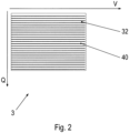
- Figure 2 shows a plan view of an attachment element 3.
- the attachment element 3 comprises a plurality of strip-shaped profiled regions 40 and a plurality of strip-shaped planar regions 32.
- the profiled regions 40 and the planar regions 32 are arranged alternately in a transverse direction Q and oriented parallel to a preferred direction V.
- the preferred direction V runs at right angles to the transverse direction Q.
- the strip-shaped profiled areas 40 of the attachment element 3 are designed in such a way that light which passes through the profiled areas 40 is refracted relatively strongly.
- a light beam 60 which originates from a point-shaped light source 1 is imaged in the form of a light strip 50 which runs in the transverse direction Q.
- Light which passes through the profiled areas 40 of the attachment element 3 creates a first image on the light-sensitive surface of the image sensor 4. The first image is blurred due to the relatively strong refraction of the light.
- the planar regions 32 of the attachment element 3 are designed in such a way that light which passes through the planar regions 32 penetrates the attachment element 3 at least approximately in a straight line, i.e. is not refracted or is only refracted insignificantly. Light which passes through the planar regions 32 of the attachment element 3 creates a second image on the light-sensitive surface of the image sensor 4.
- the second image is a sharp optical image.
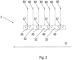
- Figure 3 shows a section through the Figure 2 shown attachment element 3.
- the section shown here runs in the transverse direction Q and perpendicular to the preferred direction V through the front element 3.
- the profiled regions 40 and the planar regions 32 are, as already mentioned, arranged alternately in the transverse direction Q.
- the planar regions 32 of the attachment element 3 have an at least approximately constant material thickness.
- the material thickness is an extension of the film in a direction perpendicular to the preferred direction V and perpendicular to the transverse direction Q. Light rays 60 thus penetrate the planar regions 32 at least approximately in a straight line and are not refracted or are refracted only insignificantly.
- the profiled areas 40 of the attachment element 3 have depressions 37 and are thus concave.
- the profiled areas 40 therefore have a lower material thickness than the planar areas 32.
- the profiled areas 40 have a constant cross-section throughout in the preferred direction V. In the present case, the profiled areas 40 have an approximately semicircular cross-section. Light rays 60 striking the profiled areas 40 are thus refracted in the transverse direction Q to varying degrees depending on the point of impact.
- the profiled areas 40 of the attachment element 3 have elevations and are thus convex.
- the profiled areas 40 have a greater material thickness than the planar areas 32.
- the cross-section of the profiled areas 40 can also deviate from the semicircular shape.
- An extension of the individual planar regions 32 in the transverse direction Y is greater than an extension of the individual profiled regions 40 in the transverse direction Y.
- the extension of the individual planar regions 32 in the transverse direction Y is approximately 4 ⁇ m
- the extension of the individual profiled regions 40 in the transverse direction Y is approximately 2 ⁇ m.
- the extension of the individual planar regions 32 in the transverse direction Y is therefore approximately three times as large as the extension of the individual profiled regions 40 in the transverse direction Y.
- the extension of the individual planar regions 32 in the transverse direction Y and the extension of the individual profiled regions 40 in the transverse direction Y should be less than 1 mm.
- FIG 4 shows a through the in Figure 2 and Figure 3 shown attachment element 3 projected overall image.
- the transmitter 14, which generates the overall image, is a motor vehicle.
- the said motor vehicle has two light sources 1, which serve as Headlights are designed.
- the two light sources 1 are to be regarded as approximately point-shaped.
- the said overall image comprises a first image which is generated by light passing through the profiled regions 40 of the attachment element 3.
- the overall image also comprises a second image which is generated by light passing through the planar regions 32 of the attachment element 3.
- the light strips 50 generated by the two light sources 1 extend in the transverse direction Q.
- the second image is a sharp optical image.
- the second image also shows relatively thin stripes with reduced brightness, which extend in the preferred direction V. These stripes are generated by parts of the profiled areas 40 of the attachment element 3, which are not hit by any light from the light sources 1. However, the said stripes are relatively thin and therefore barely visible in the overall image.
- the transmitter 14, in this case a motor vehicle, is thus clearly recognizable in the overall image.
Landscapes
- Engineering & Computer Science (AREA)
- Multimedia (AREA)
- Signal Processing (AREA)
- Physics & Mathematics (AREA)
- General Physics & Mathematics (AREA)
- Theoretical Computer Science (AREA)
- Electromagnetism (AREA)
- Computer Networks & Wireless Communication (AREA)
- Optical Communication System (AREA)
- Studio Devices (AREA)
Claims (14)
- Récepteur (12) pour un système (10) de transmission de lumière, comprenantune caméra (6) présentant un capteur d'images (4), oùune surface sensible à la lumière du capteur d'images (4) comprend plusieurs lignes d'éléments sensibles à la lumière, oùle capteur d'images (4) est mis en oeuvre de telle manière que la surface sensible à la lumière du capteur d'images (4) est balayée ligne par ligne ou colonne par colonne, et un élément optique (3) qui est agencé de telle manière quela lumière arrivant sur la surface sensible à la lumière du capteur d'images (4) traverse d'abord l'élément optique (3), oùl'élément optique (3) comprend une pluralité de régions profilées (40) en forme de bande, etles régions profilées (40) présentent une section transversale constante dans une direction préférentielle (V) qui s'étend à angle droit par rapport à la direction transversale (Q),caractérisé en ce quel'élément optique (3) comprend une pluralité de régions planes (32) en forme de bande, et en ce queles régions profilées (40) et les régions planes (32) sont agencées de manière alternée dans la direction transversale (Q).
- Récepteur (12) selon la revendication 1, caractérisé en ce que
l'élément optique (3) est réalisé sous la forme d'une feuille ou sous la forme d'une plaque, où les régions planes (32) présentent une épaisseur de matériau constante. - Récepteur (12) selon la revendication 2, caractérisé en ce que
les régions profilées (40) présentent des renfoncements (37) et une épaisseur de matériau inférieure à celle des régions planes (32). - Récepteur (12) selon la revendication 2, caractérisé en ce que
les régions profilées (40) présentent des surélévations et une épaisseur de matériau supérieure à celle des régions planes (32). - Récepteur (12) selon la revendication 2, caractérisé en ce quel'élément optique (3) comprenddes régions profilées (40) qui présentent des renfoncements (37) et une épaisseur de matériau inférieure à celle des régions planes (32) etdes régions profilées (40) qui présentent des surélévations et une épaisseur de matériau supérieure à celles des régions planes (32).
- Récepteur (12) selon l'une quelconque des revendications précédentes, caractérisé en ce que
les régions profilées (40) présentent une section transversale au moins approximativement semi-circulaire. - Récepteur (12) selon l'une quelconque des revendications précédentes, caractérisé en ce que
une extension de l'une des régions planes (32) dans la direction transversale (Y) est supérieure à une extension de l'une des régions profilées (40) dans la direction transversale (Y). - Récepteur (12) selon l'une quelconque des revendications précédentes, caractérisé en ce que l'extension de l'une des régions planes (32) dans la direction transversale (Y) est au moins deux fois supérieure à l'extension de l'une des régions profilées (40) dans la direction transversale (Y), et/ou en ce que
l'extension de l'une des régions planes (32) dans la direction transversale (Y) est au plus dix fois supérieure à celle de l'une des régions profilées (40) dans la direction transversale (Y). - Récepteur (12) selon l'une quelconque des revendications précédentes, comprenant en outre une unité d'enregistrement,
caractérisé en ce quel'unité d'enregistrement présente un premier élément d'enregistrement et un deuxième élément d'enregistrement pouvant être déplacé par rapport au premier élément d'enregistrement, oùla caméra (6) est accueillie dans le premier élément d'enregistrement, etl'élément optique (3) est accueilli dans le deuxième élément d'enregistrement. - Système (10) de transmission de lumière, comprenant
un récepteur (12) selon au moins l'une quelconque des revendications précédentes et un émetteur (14) qui présente au moins une source de lumière commandable (1) émettant de la lumière modulée en fonction d'un flux de données prédéfini. - Système (10) selon la revendication 10, caractérisé en ce que
l'élément optique (3) est agencé entre la au moins une source de lumière commandable (1) et la caméra (6). - Procédé de fonctionnement d'un système (10) de transmission de lumière selon l'une quelconque des revendications 10 à 11, caractérisé en ce quela surface sensible à la lumière du capteur d'images (4) est balayée ligne par ligne ou colonne par colonne, oùune première image projetée à travers les régions profilées (40) de l'élément optique (3) sur la zone sensible à la lumière est traitée séparément d'une deuxième image projetée à travers les régions planes (32) de l'élément optique (3) sur la zone sensible à la lumière.
- Procédé selon la revendication 12, caractérisé en ce que
le flux de données en fonction duquel la au moins une source lumineuse commandable (1) de l'émetteur (14) émet une lumière modulée est détecté à partir de la première image. - Procédé selon l'une quelconque des revendications 12 à 13, caractérisé en ce qu'une image optique est détectée à partir de la deuxième image.
Applications Claiming Priority (2)
| Application Number | Priority Date | Filing Date | Title |
|---|---|---|---|
| DE102020001892 | 2020-03-24 | ||
| PCT/EP2021/054800 WO2021190856A1 (fr) | 2020-03-24 | 2021-02-26 | Récepteur pour système de transmission de lumière, système de transmission de lumière et procédé de fonctionnement d'un système de transmission de lumière |
Publications (3)
| Publication Number | Publication Date |
|---|---|
| EP4128583A1 EP4128583A1 (fr) | 2023-02-08 |
| EP4128583C0 EP4128583C0 (fr) | 2024-04-10 |
| EP4128583B1 true EP4128583B1 (fr) | 2024-04-10 |
Family
ID=74797933
Family Applications (1)
| Application Number | Title | Priority Date | Filing Date |
|---|---|---|---|
| EP21708623.0A Active EP4128583B1 (fr) | 2020-03-24 | 2021-02-26 | Récepteur pour système de transmission de lumière, système de transmission de lumière et procédé de fonctionnement d'un système de transmission de lumière |
Country Status (4)
| Country | Link |
|---|---|
| EP (1) | EP4128583B1 (fr) |
| CN (1) | CN115136515A (fr) |
| DE (1) | DE102021001049A1 (fr) |
| WO (1) | WO2021190856A1 (fr) |
Families Citing this family (1)
| Publication number | Priority date | Publication date | Assignee | Title |
|---|---|---|---|---|
| EP4569659A1 (fr) | 2022-08-10 | 2025-06-18 | SEW-EURODRIVE GmbH & Co. KG | Procédé de détermination d'une fréquence de balayage de ligne appropriée et système de transmission de lumière |
Family Cites Families (5)
| Publication number | Priority date | Publication date | Assignee | Title |
|---|---|---|---|---|
| KR100740483B1 (ko) * | 2001-08-27 | 2007-07-19 | 가부시키가이샤 구라레 | 렌티큘러 렌즈 시트의 제조방법 |
| US7957648B2 (en) | 2005-02-28 | 2011-06-07 | The Invention Science Fund I, Llc | Electromagnetic device with integral non-linear component |
| MX343578B (es) * | 2012-12-27 | 2016-11-10 | Panasonic Ip Corp America | Metodo de comunicacion de informacion. |
| US10382130B1 (en) * | 2018-08-31 | 2019-08-13 | Ford Global Technologies, Llc | Dual mode vehicle camera for visual light communication |
| DE102018006988B3 (de) | 2018-09-04 | 2019-08-14 | Sew-Eurodrive Gmbh & Co Kg | System und Verfahren zum Betreiben dieses Systems, aufweisend eine erste Kommunikationseinheit und eine zweite Kommunikationseinheit |
-
2021
- 2021-02-26 WO PCT/EP2021/054800 patent/WO2021190856A1/fr not_active Ceased
- 2021-02-26 CN CN202180016043.7A patent/CN115136515A/zh active Pending
- 2021-02-26 DE DE102021001049.3A patent/DE102021001049A1/de active Pending
- 2021-02-26 EP EP21708623.0A patent/EP4128583B1/fr active Active
Also Published As
| Publication number | Publication date |
|---|---|
| CN115136515A (zh) | 2022-09-30 |
| US20230164412A1 (en) | 2023-05-25 |
| EP4128583A1 (fr) | 2023-02-08 |
| DE102021001049A1 (de) | 2021-09-30 |
| WO2021190856A1 (fr) | 2021-09-30 |
| EP4128583C0 (fr) | 2024-04-10 |
Similar Documents
| Publication | Publication Date | Title |
|---|---|---|
| DE69323532T2 (de) | Leser von optischen Informationen | |
| EP2290355B1 (fr) | Dispositif et procédé destinés à l'inspection de récipients étiquetés | |
| EP3847769B1 (fr) | Système et procédé pour faire fonctionner un système, comprenant une première unité de communication et une deuxième unité de communication | |
| EP1158460A2 (fr) | Système et procédé de traitement d'images | |
| EP4128583B1 (fr) | Récepteur pour système de transmission de lumière, système de transmission de lumière et procédé de fonctionnement d'un système de transmission de lumière | |
| EP2950519B1 (fr) | Caméra et procédé de capture de données d'image | |
| DE19936440A1 (de) | Optoelektronische Vorrichtung | |
| DE102016104255A1 (de) | Bildlesevorrichtung | |
| DE102019007311B3 (de) | Empfänger für ein System zur Lichtübertragung, System zur Lichtübertragung und Verfahren zum Betrieb eines Systems zur Lichtübertragung | |
| EP1503226B1 (fr) | Capteur optique | |
| EP1207491B1 (fr) | Dispositif optoélectronique | |
| EP0897123A2 (fr) | Barrière optique | |
| WO2017121627A1 (fr) | Dispositif de contrôle d'image d'impression | |
| DE102023002931A1 (de) | Verfahren zur Bestimmung einer passenden Zeilenabtastfrequenz und System zur Lichtübertragung | |
| DE102007017013A1 (de) | Reflexionsbasierte optische Codierer, die kein Codemedium aufweisen | |
| EP1130533A2 (fr) | Scanner | |
| DE2340688A1 (de) | Lesevorrichtung fuer optisch erfassbare digitale codierungen | |
| DE10205294B4 (de) | Optoelektronische Vorrichtung | |
| EP4300935B1 (fr) | Dispositif d'éclairage destiné à la génération d'un champ d'éclairage pour une caméra | |
| WO2006133972A1 (fr) | Dispositif pour photographier des pieces de monnaie dans un appareil de verification de pieces de monnaie | |
| DE20005283U1 (de) | Gabellichtschranke | |
| DE10349106B4 (de) | Vorrichtung zum Sammeln von optischen Signalen | |
| DE112006003116T5 (de) | Abtastvorrichtung mit Führung von Lichtstrahlen | |
| DE102007057283B4 (de) | Verfahren zum Justieren einer Einweg-Lichtschranke | |
| EP4270087A1 (fr) | Balayeur laser et pyramide de miroir et son procédé de production |
Legal Events
| Date | Code | Title | Description |
|---|---|---|---|
| STAA | Information on the status of an ep patent application or granted ep patent |
Free format text: STATUS: UNKNOWN |
|
| STAA | Information on the status of an ep patent application or granted ep patent |
Free format text: STATUS: THE INTERNATIONAL PUBLICATION HAS BEEN MADE |
|
| PUAI | Public reference made under article 153(3) epc to a published international application that has entered the european phase |
Free format text: ORIGINAL CODE: 0009012 |
|
| STAA | Information on the status of an ep patent application or granted ep patent |
Free format text: STATUS: REQUEST FOR EXAMINATION WAS MADE |
|
| 17P | Request for examination filed |
Effective date: 20221024 |
|
| AK | Designated contracting states |
Kind code of ref document: A1 Designated state(s): AL AT BE BG CH CY CZ DE DK EE ES FI FR GB GR HR HU IE IS IT LI LT LU LV MC MK MT NL NO PL PT RO RS SE SI SK SM TR |
|
| DAV | Request for validation of the european patent (deleted) | ||
| DAX | Request for extension of the european patent (deleted) | ||
| GRAP | Despatch of communication of intention to grant a patent |
Free format text: ORIGINAL CODE: EPIDOSNIGR1 |
|
| STAA | Information on the status of an ep patent application or granted ep patent |
Free format text: STATUS: GRANT OF PATENT IS INTENDED |
|
| INTG | Intention to grant announced |
Effective date: 20231025 |
|
| GRAS | Grant fee paid |
Free format text: ORIGINAL CODE: EPIDOSNIGR3 |
|
| GRAA | (expected) grant |
Free format text: ORIGINAL CODE: 0009210 |
|
| STAA | Information on the status of an ep patent application or granted ep patent |
Free format text: STATUS: THE PATENT HAS BEEN GRANTED |
|
| AK | Designated contracting states |
Kind code of ref document: B1 Designated state(s): AL AT BE BG CH CY CZ DE DK EE ES FI FR GB GR HR HU IE IS IT LI LT LU LV MC MK MT NL NO PL PT RO RS SE SI SK SM TR |
|
| REG | Reference to a national code |
Ref country code: GB Ref legal event code: FG4D Free format text: NOT ENGLISH |
|
| REG | Reference to a national code |
Ref country code: CH Ref legal event code: EP |
|
| REG | Reference to a national code |
Ref country code: DE Ref legal event code: R096 Ref document number: 502021003307 Country of ref document: DE |
|
| REG | Reference to a national code |
Ref country code: IE Ref legal event code: FG4D Free format text: LANGUAGE OF EP DOCUMENT: GERMAN |
|
| U01 | Request for unitary effect filed |
Effective date: 20240417 |
|
| U07 | Unitary effect registered |
Designated state(s): AT BE BG DE DK EE FI FR IT LT LU LV MT NL PT SE SI Effective date: 20240514 |
|
| PG25 | Lapsed in a contracting state [announced via postgrant information from national office to epo] |
Ref country code: IS Free format text: LAPSE BECAUSE OF FAILURE TO SUBMIT A TRANSLATION OF THE DESCRIPTION OR TO PAY THE FEE WITHIN THE PRESCRIBED TIME-LIMIT Effective date: 20240810 |
|
| PG25 | Lapsed in a contracting state [announced via postgrant information from national office to epo] |
Ref country code: HR Free format text: LAPSE BECAUSE OF FAILURE TO SUBMIT A TRANSLATION OF THE DESCRIPTION OR TO PAY THE FEE WITHIN THE PRESCRIBED TIME-LIMIT Effective date: 20240410 |
|
| PG25 | Lapsed in a contracting state [announced via postgrant information from national office to epo] |
Ref country code: GR Free format text: LAPSE BECAUSE OF FAILURE TO SUBMIT A TRANSLATION OF THE DESCRIPTION OR TO PAY THE FEE WITHIN THE PRESCRIBED TIME-LIMIT Effective date: 20240711 |
|
| PG25 | Lapsed in a contracting state [announced via postgrant information from national office to epo] |
Ref country code: ES Free format text: LAPSE BECAUSE OF FAILURE TO SUBMIT A TRANSLATION OF THE DESCRIPTION OR TO PAY THE FEE WITHIN THE PRESCRIBED TIME-LIMIT Effective date: 20240410 |
|
| PG25 | Lapsed in a contracting state [announced via postgrant information from national office to epo] |
Ref country code: PL Free format text: LAPSE BECAUSE OF FAILURE TO SUBMIT A TRANSLATION OF THE DESCRIPTION OR TO PAY THE FEE WITHIN THE PRESCRIBED TIME-LIMIT Effective date: 20240410 |
|
| PG25 | Lapsed in a contracting state [announced via postgrant information from national office to epo] |
Ref country code: PL Free format text: LAPSE BECAUSE OF FAILURE TO SUBMIT A TRANSLATION OF THE DESCRIPTION OR TO PAY THE FEE WITHIN THE PRESCRIBED TIME-LIMIT Effective date: 20240410 Ref country code: NO Free format text: LAPSE BECAUSE OF FAILURE TO SUBMIT A TRANSLATION OF THE DESCRIPTION OR TO PAY THE FEE WITHIN THE PRESCRIBED TIME-LIMIT Effective date: 20240710 Ref country code: IS Free format text: LAPSE BECAUSE OF FAILURE TO SUBMIT A TRANSLATION OF THE DESCRIPTION OR TO PAY THE FEE WITHIN THE PRESCRIBED TIME-LIMIT Effective date: 20240810 Ref country code: HR Free format text: LAPSE BECAUSE OF FAILURE TO SUBMIT A TRANSLATION OF THE DESCRIPTION OR TO PAY THE FEE WITHIN THE PRESCRIBED TIME-LIMIT Effective date: 20240410 Ref country code: GR Free format text: LAPSE BECAUSE OF FAILURE TO SUBMIT A TRANSLATION OF THE DESCRIPTION OR TO PAY THE FEE WITHIN THE PRESCRIBED TIME-LIMIT Effective date: 20240711 Ref country code: ES Free format text: LAPSE BECAUSE OF FAILURE TO SUBMIT A TRANSLATION OF THE DESCRIPTION OR TO PAY THE FEE WITHIN THE PRESCRIBED TIME-LIMIT Effective date: 20240410 Ref country code: RS Free format text: LAPSE BECAUSE OF FAILURE TO SUBMIT A TRANSLATION OF THE DESCRIPTION OR TO PAY THE FEE WITHIN THE PRESCRIBED TIME-LIMIT Effective date: 20240710 |
|
| REG | Reference to a national code |
Ref country code: DE Ref legal event code: R097 Ref document number: 502021003307 Country of ref document: DE |
|
| PG25 | Lapsed in a contracting state [announced via postgrant information from national office to epo] |
Ref country code: CZ Free format text: LAPSE BECAUSE OF FAILURE TO SUBMIT A TRANSLATION OF THE DESCRIPTION OR TO PAY THE FEE WITHIN THE PRESCRIBED TIME-LIMIT Effective date: 20240410 |
|
| PG25 | Lapsed in a contracting state [announced via postgrant information from national office to epo] |
Ref country code: RO Free format text: LAPSE BECAUSE OF FAILURE TO SUBMIT A TRANSLATION OF THE DESCRIPTION OR TO PAY THE FEE WITHIN THE PRESCRIBED TIME-LIMIT Effective date: 20240410 Ref country code: SK Free format text: LAPSE BECAUSE OF FAILURE TO SUBMIT A TRANSLATION OF THE DESCRIPTION OR TO PAY THE FEE WITHIN THE PRESCRIBED TIME-LIMIT Effective date: 20240410 |
|
| PG25 | Lapsed in a contracting state [announced via postgrant information from national office to epo] |
Ref country code: SM Free format text: LAPSE BECAUSE OF FAILURE TO SUBMIT A TRANSLATION OF THE DESCRIPTION OR TO PAY THE FEE WITHIN THE PRESCRIBED TIME-LIMIT Effective date: 20240410 |
|
| PG25 | Lapsed in a contracting state [announced via postgrant information from national office to epo] |
Ref country code: SM Free format text: LAPSE BECAUSE OF FAILURE TO SUBMIT A TRANSLATION OF THE DESCRIPTION OR TO PAY THE FEE WITHIN THE PRESCRIBED TIME-LIMIT Effective date: 20240410 Ref country code: SK Free format text: LAPSE BECAUSE OF FAILURE TO SUBMIT A TRANSLATION OF THE DESCRIPTION OR TO PAY THE FEE WITHIN THE PRESCRIBED TIME-LIMIT Effective date: 20240410 Ref country code: RO Free format text: LAPSE BECAUSE OF FAILURE TO SUBMIT A TRANSLATION OF THE DESCRIPTION OR TO PAY THE FEE WITHIN THE PRESCRIBED TIME-LIMIT Effective date: 20240410 Ref country code: CZ Free format text: LAPSE BECAUSE OF FAILURE TO SUBMIT A TRANSLATION OF THE DESCRIPTION OR TO PAY THE FEE WITHIN THE PRESCRIBED TIME-LIMIT Effective date: 20240410 |
|
| PLBE | No opposition filed within time limit |
Free format text: ORIGINAL CODE: 0009261 |
|
| STAA | Information on the status of an ep patent application or granted ep patent |
Free format text: STATUS: NO OPPOSITION FILED WITHIN TIME LIMIT |
|
| 26N | No opposition filed |
Effective date: 20250113 |
|
| U20 | Renewal fee for the european patent with unitary effect paid |
Year of fee payment: 5 Effective date: 20250228 |
|
| PGFP | Annual fee paid to national office [announced via postgrant information from national office to epo] |
Ref country code: GB Payment date: 20250102 Year of fee payment: 5 |
|
| PG25 | Lapsed in a contracting state [announced via postgrant information from national office to epo] |
Ref country code: MC Free format text: LAPSE BECAUSE OF FAILURE TO SUBMIT A TRANSLATION OF THE DESCRIPTION OR TO PAY THE FEE WITHIN THE PRESCRIBED TIME-LIMIT Effective date: 20240410 |
|
| REG | Reference to a national code |
Ref country code: CH Ref legal event code: PL |
|
| PG25 | Lapsed in a contracting state [announced via postgrant information from national office to epo] |
Ref country code: CH Free format text: LAPSE BECAUSE OF NON-PAYMENT OF DUE FEES Effective date: 20250228 |
|
| PG25 | Lapsed in a contracting state [announced via postgrant information from national office to epo] |
Ref country code: IE Free format text: LAPSE BECAUSE OF NON-PAYMENT OF DUE FEES Effective date: 20250226 |