EP4128560B1 - Sättigungsabschwächung einer kanalqualitätsanzeige (cqi) - Google Patents
Sättigungsabschwächung einer kanalqualitätsanzeige (cqi) Download PDFInfo
- Publication number
- EP4128560B1 EP4128560B1 EP21717540.5A EP21717540A EP4128560B1 EP 4128560 B1 EP4128560 B1 EP 4128560B1 EP 21717540 A EP21717540 A EP 21717540A EP 4128560 B1 EP4128560 B1 EP 4128560B1
- Authority
- EP
- European Patent Office
- Prior art keywords
- cqi
- csi
- signal
- resource
- power level
- Prior art date
- Legal status (The legal status is an assumption and is not a legal conclusion. Google has not performed a legal analysis and makes no representation as to the accuracy of the status listed.)
- Active
Links
Images


Classifications
-
- H—ELECTRICITY
- H04—ELECTRIC COMMUNICATION TECHNIQUE
- H04L—TRANSMISSION OF DIGITAL INFORMATION, e.g. TELEGRAPHIC COMMUNICATION
- H04L1/00—Arrangements for detecting or preventing errors in the information received
- H04L1/0001—Systems modifying transmission characteristics according to link quality, e.g. power backoff
- H04L1/0023—Systems modifying transmission characteristics according to link quality, e.g. power backoff characterised by the signalling
- H04L1/0026—Transmission of channel quality indication
-
- H—ELECTRICITY
- H04—ELECTRIC COMMUNICATION TECHNIQUE
- H04B—TRANSMISSION
- H04B7/00—Radio transmission systems, i.e. using radiation field
- H04B7/02—Diversity systems; Multi-antenna system, i.e. transmission or reception using multiple antennas
- H04B7/04—Diversity systems; Multi-antenna system, i.e. transmission or reception using multiple antennas using two or more spaced independent antennas
- H04B7/0413—MIMO systems
- H04B7/0452—Multi-user MIMO systems
-
- H—ELECTRICITY
- H04—ELECTRIC COMMUNICATION TECHNIQUE
- H04B—TRANSMISSION
- H04B7/00—Radio transmission systems, i.e. using radiation field
- H04B7/02—Diversity systems; Multi-antenna system, i.e. transmission or reception using multiple antennas
- H04B7/04—Diversity systems; Multi-antenna system, i.e. transmission or reception using multiple antennas using two or more spaced independent antennas
- H04B7/06—Diversity systems; Multi-antenna system, i.e. transmission or reception using multiple antennas using two or more spaced independent antennas at the transmitting station
- H04B7/0613—Diversity systems; Multi-antenna system, i.e. transmission or reception using multiple antennas using two or more spaced independent antennas at the transmitting station using simultaneous transmission
- H04B7/0615—Diversity systems; Multi-antenna system, i.e. transmission or reception using multiple antennas using two or more spaced independent antennas at the transmitting station using simultaneous transmission of weighted versions of same signal
- H04B7/0619—Diversity systems; Multi-antenna system, i.e. transmission or reception using multiple antennas using two or more spaced independent antennas at the transmitting station using simultaneous transmission of weighted versions of same signal using feedback from receiving side
- H04B7/0621—Feedback content
- H04B7/0632—Channel quality parameters, e.g. channel quality indicator [CQI]
-
- H—ELECTRICITY
- H04—ELECTRIC COMMUNICATION TECHNIQUE
- H04W—WIRELESS COMMUNICATION NETWORKS
- H04W52/00—Power management, e.g. Transmission Power Control [TPC] or power classes
- H04W52/04—Transmission power control [TPC]
- H04W52/18—TPC being performed according to specific parameters
- H04W52/24—TPC being performed according to specific parameters using SIR [Signal to Interference Ratio] or other wireless path parameters
- H04W52/241—TPC being performed according to specific parameters using SIR [Signal to Interference Ratio] or other wireless path parameters taking into account channel quality metrics, e.g. SIR, SNR, CIR or Eb/lo
-
- H—ELECTRICITY
- H04—ELECTRIC COMMUNICATION TECHNIQUE
- H04W—WIRELESS COMMUNICATION NETWORKS
- H04W52/00—Power management, e.g. Transmission Power Control [TPC] or power classes
- H04W52/04—Transmission power control [TPC]
- H04W52/18—TPC being performed according to specific parameters
- H04W52/24—TPC being performed according to specific parameters using SIR [Signal to Interference Ratio] or other wireless path parameters
- H04W52/243—TPC being performed according to specific parameters using SIR [Signal to Interference Ratio] or other wireless path parameters taking into account interferences
Definitions
- CQI channel quality indication
- multiple-input and multiple-output (MIMO) technology is becoming more and more popular and has been incorporated into wireless broadband standards like 4 th Generation (4G) Long Term Evolution (LTE) and 5 th Generation (5G) New Radio (NR).
- 4G Long Term Evolution
- 5G 5 th Generation
- DL Downlink
- eNB eNode
- gNB eNode
- UE user equipment
- Downlink MU-MIMO is usually a close-loop MIMO system, i.e., the downlink channel state information (CSI) perceived on the wireless device is feedback to the network node and used by network node to determine downlink transmission format, i.e., transmission block size (TBS), rank and modulation and coding rate scheme (MCS).
- CSI reporting as specified in Third Generation Partnership Project (3GPP) 4G LTE and 5G NR assumes single user (SU) MIMO transmission as a wireless device does not know, when it sends the CSI report, how and which multiple wireless devices it will be paired with in future transmissions. This SU CSI report is not accurate if it is directly used to determine MU MIMO transmission format when multiple wireless devices are paired together for downlink transmission.
- 3GPP Third Generation Partnership Project
- 4G LTE and 5G NR assumes single user (SU) MIMO transmission as a wireless device does not know, when it sends the CSI report, how and which multiple wireless devices it will be paired with in future transmission
- the downlink transmit power will be shared by all paired wireless devices; and second, multiple paired wireless devices together using same time/frequency resource for transmission will introduce additional inter-stream interference. Both power sharing and inter-stream interference from other paired wireless devices will contribute to the decrease of signal to interference plus noise ratio (SINR) for each paired wireless device and create a gap between actual MU-MIMO CSI and wireless device reported CSI.
- SINR signal to interference plus noise ratio
- CQI channel quality indication
- One issue with wireless device's CSI report is CQI saturation. In case actual downlink post equalization SINR is higher than the SINR corresponding to highest CQI, i.e., CQI of 15, the reported CQI SINR will be capped.
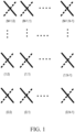
- FIG. 1 illustrates such a system.
- a CSI report includes channel quality indication (CQI), precoding matrix indication (PMI) and rank indication (RI) and CSI-RS resource indication (CRI).
- CQI can be considered as quantized SINR to achieve as closely as possible the desired coding rate indicated by CQI index for reported PMI and RI (3GPP TS 36.213 for LTE and 3GPP TS38.214 for NR).
- the highest CQI index 15 represents SINR needed to achieved highest coding rate supported by standard for given PMI and RI, which is roughly 20dB for LTE and NR when 64QAM is used and about 27 dB when 256QAM is configured.
- ⁇ CQI 15 be the SINR corresponding to CQI 15.
- CQI 15 will be reported as illustrated in FIG. 2 . That is, CQI 1 to the first instance of CQI 15 in FIG. 2 corresponds to a linear or substantially linear region where increased SINR corresponds to an increase in CQI, which corresponds to a non-saturated region.
- every increase in SINR does not correspond to an increase in CQI as the maximum reportable CQI is 15, which corresponds to a saturated region.
- SINR of 20 will be reported as CQI 15 even though the first instant of CQI 15 corresponds to an SINR of 18.
- the network node has no knowledge of the actual downlink SINR when CQI 15 is reported.
- the wireless device reported CQI will be reduced due to the power split between wireless devices and due to extra inter-stream interference between paired wireless devices.
- the estimated MU-MIMO SINR on and/or by the network node will be conservative (i.e., lower or substantially lower than the actual DL SINR) as illustrated in FIG. 3 and result in poor system performance.
- one solution is to configure multiple CSI-RS resources for each wireless device to an extended CQI linear range at low end and high end of SINR.
- a different powerControlOffset is configured for different CSI-RS resources.
- the wireless device can scale down (or up) the signal first and then estimate the SINR, so that the wireless device can shift the SNR range in the CQI report from [-9dB, 20dB] to [(-9+ powerControlOffset)dB, (20+ powerControlOffset)dB], thereby helping reduce the CQI saturation probability.
- different number of CSI-RS antenna ports and/or different beamforming are performed for different CSI-RS resources. By reducing the beamforming gain, the CQI can tolerate higher received signal, thus reduce the CQI saturation probability.
- Configuring multiple CSI-RS resources generally need for the wireless device to support more CSI-RS ports. For example, most of existing commercial networks utilize 32-port CSI-RS to achieve optimum performance. Therefore, when two CSI-RS resources are configured, the total Tx ports the wireless device needs to support is 64 (32+32). However, due to CSI-RS complexity restriction, most of commercial wireless devices only support up to 32 ports in total.
- one low complexity solution is to configure two CSI-RS resources and each with less antenna ports, i.e., 16 ports or less. Since less CSI-RS antenna ports are used for CSI feedback, this will negatively impact the CSI feedback accuracy and thus introduce some performance loss for type-I codebook based SU-MIMO performance. Furthermore, if 16 ports are configured for MU-MIMO and 32 ports are configured for SU-MIMO, this will break the smooth switch between SU-MIMO and MU-MIMO which is important for real world systems.
- a user equipment may generate and send a plurality of channel quality indicator (CQI) values to a base station.
- CQI channel quality indicator
- the base station determines whether at least some of the received CQI values are outside of an upper or lower threshold value. If at least some of the received CQI values are outside the upper or lower threshold value, the base station can transmit an adjusted measurement power offset to the user equipment.
- the user equipment On receipt of the adjusted measurement power offset, the user equipment generates sub-sequent CQI values using the adjusted measurement power offset.
- a method includes receiving signaling including a first Non-Zero Power (NZP) CSI-reference signal (RS) configuration for channel measurement; a second NZP CSI-RS configuration; and a CSI interference measurement (CSI-IM) configuration for interference measurement.
- the method includes receiving a CSI feedback request and estimating the CSI based on at least the signaled first NZP CSI-RS configuration, the second NZP CSI-RS configuration, and the CSI-IM configuration.
- NZP Non-Zero Power
- RS Non-Zero Power
- CSI-IM CSI interference measurement
- the invention is defined by the subject-matter of independent claims 1, 7, 13 and 14, which define a method at a network node, a method at a wireless device, a network node and a wireless device, respectively, for CQI saturation mitigation.
- the present disclosure includes several embodiments of methods, which can be deployed jointly, to mitigate the CQI saturation issue for wireless devices with limited CSI feedback capability for downlink massive MIMO systems. These embodiments may include:
- any of the above-mentioned transmission powers can be zero.
- Embodiments of the methods disclosed herein enable a wireless device with limited capability to have multiple CSI report(s) to mitigate the SINR saturation issue encountered in downlink massive MU-MIMO system. With these embodiments, the CSI estimation on the base station will be more accurate which may improve massive MU-MIMO performance in 4G LTE and 5G NR systems, for example.
- relational terms such as “first” and “second,” “top” and “bottom,” and the like, may be used solely to distinguish one entity or element from another entity or element without necessarily requiring or implying any physical or logical relationship or order between such entities or elements.
- the terminology used herein is for the purpose of describing particular embodiments only and is not intended to be limiting of the concepts described herein.
- the singular forms “a”, “an” and “the” are intended to include the plural forms as well, unless the context clearly indicates otherwise.
- the joining term, "in communication with” and the like may be used to indicate electrical or data communication, which may be accomplished by physical contact, induction, electromagnetic radiation, radio signaling, infrared signaling or optical signaling, for example.
- electrical or data communication may be accomplished by physical contact, induction, electromagnetic radiation, radio signaling, infrared signaling or optical signaling, for example.
- Coupled may be used herein to indicate a connection, although not necessarily directly, and may include wired and/or wireless connections.
- network node can be any kind of network node comprised in a radio network which may further comprise any of base station (BS), radio base station, base transceiver station (BTS), base station controller (BSC), radio network controller (RNC), g Node B (gNB), evolved Node B (eNB or eNodeB), Node B, multi-standard radio (MSR) radio node such as MSR BS, multi-cell/multicast coordination entity (MCE), integrated access and backhaul (IAB) node, relay node, donor node controlling relay, radio access point (AP), transmission points, transmission nodes, Remote Radio Unit (RRU) Remote Radio Head (RRH), a core network node (e.g., mobile management entity (MME), self-organizing network (SON) node, a coordinating node, positioning node, MDT node, etc.), an external node (e.g., 3rd party node, a node external to the current network), nodes in distributed antenna system (
- BS base station
- wireless device and a user equipment (UE) may be used interchangeably herein.
- the WD herein can be any type of wireless device capable of communicating with a network node or another WD over radio signals, such as wireless device (WD).
- the WD may also be a radio communication device, target device, device to device (D2D) WD, machine type WD or WD capable of machine to machine communication (M2M), low-cost and/or low-complexity WD, a sensor equipped with WD, Tablet, mobile terminals, smart phone, laptop embedded equipped (LEE), laptop mounted equipment (LME), USB dongles, Customer Premises Equipment (CPE), an Internet of Things (IoT) device, or a Narrowband IoT (NB-IOT) device, etc.
- D2D device to device
- M2M machine to machine communication
- M2M machine to machine communication
- Tablet mobile terminals
- smart phone laptop embedded equipped (LEE), laptop mounted equipment (LME), USB dongles
- CPE Customer Premises Equipment
- IoT Internet of Things
- NB-IOT Narrowband IoT
- radio network node can be any kind of a radio network node which may comprise any of base station, radio base station, base transceiver station, base station controller, network controller, RNC, evolved Node B (eNB), Node B, gNB, Multi-cell/multicast Coordination Entity (MCE), IAB node, relay node, access point, radio access point, Remote Radio Unit (RRU) Remote Radio Head (RRH).
- RNC evolved Node B
- MCE Multi-cell/multicast Coordination Entity
- IAB node IAB node
- relay node relay node
- access point radio access point
- RRU Remote Radio Unit
- RRH Remote Radio Head
- WCDMA Wide Band Code Division Multiple Access
- WiMax Worldwide Interoperability for Microwave Access
- UMB Ultra Mobile Broadband
- GSM Global System for Mobile Communications
- functions described herein as being performed by a wireless device or a network node may be distributed over a plurality of wireless devices and/or network nodes.
- the functions of the network node and wireless device described herein are not limited to performance by a single physical device and, in fact, can be distributed among several physical devices.
- mitigating CQI saturation refers to reducing a likelihood for CQI saturation and/or preventing CQI saturation.
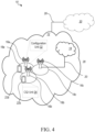
- FIG. 4 a schematic diagram of a communication system 10, according to an embodiment, such as a 3GPP-type cellular network that may support standards such as LTE and/or NR (5G), which comprises an access network 12, such as a radio access network, and a core network 14.
- the access network 12 comprises a plurality of network nodes 16a, 16b, 16c (referred to collectively as network nodes 16), such as NBs, eNBs, gNBs or other types of wireless access points, each defining a corresponding coverage area 18a, 18b, 18c (referred to collectively as coverage areas 18).
- Each network node 16a, 16b, 16c is connectable to the core network 14 over a wired or wireless connection 20.
- a first wireless device (WD) 22a located in coverage area 18a is configured to wirelessly connect to, or be paged by, the corresponding network node 16a.
- a second WD 22b in coverage area 18b is wirelessly connectable to the corresponding network node 16b. While a plurality of WDs 22a, 22b (collectively referred to as wireless devices 22) are illustrated in this example, the disclosed embodiments are equally applicable to a situation where a sole WD is in the coverage area or where a sole WD is connecting to the corresponding network node 16. Note that although only two WDs 22 and three network nodes 16 are shown for convenience, the communication system may include many more WDs 22 and network nodes 16.
- a WD 22 can be in simultaneous communication and/or configured to separately communicate with more than one network node 16 and more than one type of network node 16.
- a WD 22 can have dual connectivity with a network node 16 that supports LTE and the same or a different network node 16 that supports NR.
- WD 22 can be in communication with an eNB for LTE/E-UTRAN and a gNB for NR/NG-RAN.
- the communication system 10 may itself be connected to a host computer 24, which may be embodied in the hardware and/or software of a standalone server, a cloud-implemented server, a distributed server or as processing resources in a server farm.
- the host computer 24 may be under the ownership or control of a service provider, or may be operated by the service provider or on behalf of the service provider.
- the connections 26, 28 between the communication system 10 and the host computer 24 may extend directly from the core network 14 to the host computer 24 or may extend via an optional intermediate network 30.
- the intermediate network 30 may be one of, or a combination of more than one of, a public, private or hosted network.
- the intermediate network 30, if any, may be a backbone network or the Internet. In some embodiments, the intermediate network 30 may comprise two or more sub-networks (not shown).
- the communication system of FIG. 4 as a whole enables connectivity between one of the connected WDs 22a, 22b and the host computer 24.
- the connectivity may be described as an over-the-top (OTT) connection.
- the host computer 24 and the connected WDs 22a, 22b are configured to communicate data and/or signaling via the OTT connection, using the access network 12, the core network 14, any intermediate network 30 and possible further infrastructure (not shown) as intermediaries.
- the OTT connection may be transparent in the sense that at least some of the participating communication devices through which the OTT connection passes are unaware of routing of uplink and downlink communications.
- a network node 16 may not or need not be informed about the past routing of an incoming downlink communication with data originating from a host computer 24 to be forwarded (e.g., handed over) to a connected WD 22a. Similarly, the network node 16 need not be aware of the future routing of an outgoing uplink communication originating from the WD 22a towards the host computer 24.
- a network node 16 is configured to include a configuration unit 32 which is configured to perform one or more network node 16 functions as described herein such as with respect to CQI saturation mitigation.
- a wireless device 22 is configured to include a CQI unit 34 which is configured to perform one or more wireless device 22 functions as described herein such as with respect to CQI saturation mitigation.
- a host computer 24 comprises hardware (HW) 38 including a communication interface 40 configured to set up and maintain a wired or wireless connection with an interface of a different communication device of the communication system 10.
- the host computer 24 further comprises processing circuitry 42, which may have storage and/or processing capabilities.
- the processing circuitry 42 may include a processor 44 and memory 46.
- the processing circuitry 42 may comprise integrated circuitry for processing and/or control, e.g., one or more processors and/or processor cores and/or FPGAs (Field Programmable Gate Array) and/or ASICs (Application Specific Integrated Circuitry) adapted to execute instructions.
- processors and/or processor cores and/or FPGAs Field Programmable Gate Array
- ASICs Application Specific Integrated Circuitry
- the processor 44 may be configured to access (e.g., write to and/or read from) memory 46, which may comprise any kind of volatile and/or nonvolatile memory, e.g., cache and/or buffer memory and/or RAM (Random Access Memory) and/or ROM (Read-Only Memory) and/or optical memory and/or EPROM (Erasable Programmable Read-Only Memory).
- memory 46 may comprise any kind of volatile and/or nonvolatile memory, e.g., cache and/or buffer memory and/or RAM (Random Access Memory) and/or ROM (Read-Only Memory) and/or optical memory and/or EPROM (Erasable Programmable Read-Only Memory).
- Processing circuitry 42 may be configured to control any of the methods and/or processes described herein and/or to cause such methods, and/or processes to be performed, e.g., by host computer 24.
- Processor 44 corresponds to one or more processors 44 for performing host computer 24 functions described herein.
- the host computer 24 includes memory 46 that is configured to store data, programmatic software code and/or other information described herein.
- the software 48 and/or the host application 50 may include instructions that, when executed by the processor 44 and/or processing circuitry 42, causes the processor 44 and/or processing circuitry 42 to perform the processes described herein with respect to host computer 24.
- the instructions may be software associated with the host computer 24.
- the software 48 may be executable by the processing circuitry 42.
- the software 48 includes a host application 50.
- the host application 50 may be operable to provide a service to a remote user, such as a WD 22 connecting via an OTT connection 52 terminating at the WD 22 and the host computer 24.
- the host application 50 may provide user data which is transmitted using the OTT connection 52.
- the "user data" may be data and information described herein as implementing the described functionality.
- the host computer 24 may be configured for providing control and functionality to a service provider and may be operated by the service provider or on behalf of the service provider.
- the processing circuitry 42 of the host computer 24 may enable the host computer 24 to observe, monitor, control, transmit to and/or receive from the network node 16 and or the wireless device 22.
- the processing circuitry 42 of the host computer 24 may include an information unit 54 configured to enable the service provider to process, analyze, forward, relay, transmit, receive, store, etc., information related to CQI saturation mitigation.
- the communication system 10 further includes a network node 16 provided in a communication system 10 and including hardware 58 enabling it to communicate with the host computer 24 and with the WD 22.
- the hardware 58 may include a communication interface 60 for setting up and maintaining a wired or wireless connection with an interface of a different communication device of the communication system 10, as well as a radio interface 62 for setting up and maintaining at least a wireless connection 64 with a WD 22 located in a coverage area 18 served by the network node 16.
- the radio interface 62 may be formed as or may include, for example, one or more RF transmitters, one or more RF receivers, and/or one or more RF transceivers.
- the communication interface 60 may be configured to facilitate a connection 66 to the host computer 24.
- the connection 66 may be direct or it may pass through a core network 14 of the communication system 10 and/or through one or more intermediate networks 30 outside the communication system 10.
- the hardware 58 of the network node 16 further includes processing circuitry 68.
- the processing circuitry 68 may include a processor 70 and a memory 72.
- the processing circuitry 68 may comprise integrated circuitry for processing and/or control, e.g., one or more processors and/or processor cores and/or FPGAs (Field Programmable Gate Array) and/or ASICs (Application Specific Integrated Circuitry) adapted to execute instructions.
- FPGAs Field Programmable Gate Array
- ASICs Application Specific Integrated Circuitry
- the processor 70 may be configured to access (e.g., write to and/or read from) the memory 72, which may comprise any kind of volatile and/or nonvolatile memory, e.g., cache and/or buffer memory and/or RAM (Random Access Memory) and/or ROM (Read-Only Memory) and/or optical memory and/or EPROM (Erasable Programmable Read-Only Memory).
- volatile and/or nonvolatile memory e.g., cache and/or buffer memory and/or RAM (Random Access Memory) and/or ROM (Read-Only Memory) and/or optical memory and/or EPROM (Erasable Programmable Read-Only Memory).
- the network node 16 further has software 74 stored internally in, for example, memory 72, or stored in external memory (e.g., database, storage array, network storage device, etc.) accessible by the network node 16 via an external connection.
- the software 74 may be executable by the processing circuitry 68.
- the processing circuitry 68 may be configured to control any of the methods and/or processes described herein and/or to cause such methods, and/or processes to be performed, e.g., by network node 16.
- Processor 70 corresponds to one or more processors 70 for performing network node 16 functions described herein.
- the memory 72 is configured to store data, programmatic software code and/or other information described herein.
- the software 74 may include instructions that, when executed by the processor 70 and/or processing circuitry 68, causes the processor 70 and/or processing circuitry 68 to perform the processes described herein with respect to network node 16.
- processing circuitry 68 of the network node 16 may include configuration unit 32 configured to perform one or more network node 16 functions as described herein such as with respect to CQI saturation mitigation.
- the communication system 10 further includes the WD 22 already referred to.
- the WD 22 may have hardware 80 that may include a radio interface 82 configured to set up and maintain a wireless connection 64 with a network node 16 serving a coverage area 18 in which the WD 22 is currently located.
- the radio interface 82 may be formed as or may include, for example, one or more RF transmitters, one or more RF receivers, and/or one or more RF transceivers.
- the hardware 80 of the WD 22 further includes processing circuitry 84.
- the processing circuitry 84 may include a processor 86 and memory 88.
- the processing circuitry 84 may comprise integrated circuitry for processing and/or control, e.g., one or more processors and/or processor cores and/or FPGAs (Field Programmable Gate Array) and/or ASICs (Application Specific Integrated Circuitry) adapted to execute instructions.
- the processor 86 may be configured to access (e.g., write to and/or read from) memory 88, which may comprise any kind of volatile and/or nonvolatile memory, e.g., cache and/or buffer memory and/or RAM (Random Access Memory) and/or ROM (Read-Only Memory) and/or optical memory and/or EPROM (Erasable Programmable Read-Only Memory).
- memory 88 may comprise any kind of volatile and/or nonvolatile memory, e.g., cache and/or buffer memory and/or RAM (Random Access Memory) and/or ROM (Read-Only Memory) and/or optical memory and/or EPROM (Erasable Programmable Read-Only Memory).
- the WD 22 may further comprise software 90, which is stored in, for example, memory 88 at the WD 22, or stored in external memory (e.g., database, storage array, network storage device, etc.) accessible by the WD 22.
- the software 90 may be executable by the processing circuitry 84.
- the software 90 may include a client application 92.
- the client application 92 may be operable to provide a service to a human or non-human user via the WD 22, with the support of the host computer 24.
- an executing host application 50 may communicate with the executing client application 92 via the OTT connection 52 terminating at the WD 22 and the host computer 24.
- the client application 92 may receive request data from the host application 50 and provide user data in response to the request data.
- the OTT connection 52 may transfer both the request data and the user data.
- the client application 92 may interact with the user to generate the user data that it provides.
- the processing circuitry 84 may be configured to control any of the methods and/or processes described herein and/or to cause such methods, and/or processes to be performed, e.g., by WD 22.
- the processor 86 corresponds to one or more processors 86 for performing WD 22 functions described herein.
- the WD 22 includes memory 88 that is configured to store data, programmatic software code and/or other information described herein.
- the software 90 and/or the client application 92 may include instructions that, when executed by the processor 86 and/or processing circuitry 84, causes the processor 86 and/or processing circuitry 84 to perform the processes described herein with respect to WD 22.
- the processing circuitry 84 of the wireless device 22 may include a CQI unit 34 configured to perform one or more wireless device 22 functions as described herein such as with respect to CQI saturation mitigation.
- the inner workings of the network node 16, WD 22, and host computer 24 may be as shown in FIG. 5 and independently, the surrounding network topology may be that of FIG. 4 .
- the OTT connection 52 has been drawn abstractly to illustrate the communication between the host computer 24 and the wireless device 22 via the network node 16, without explicit reference to any intermediary devices and the precise routing of messages via these devices.
- Network infrastructure may determine the routing, which it may be configured to hide from the WD 22 or from the service provider operating the host computer 24, or both. While the OTT connection 52 is active, the network infrastructure may further take decisions by which it dynamically changes the routing (e.g., on the basis of load balancing consideration or reconfiguration of the network).
- the wireless connection 64 between the WD 22 and the network node 16 is in accordance with the teachings of the embodiments described throughout this disclosure.
- One or more of the various embodiments improve the performance of OTT services provided to the WD 22 using the OTT connection 52, in which the wireless connection 64 may form the last segment. More precisely, the teachings of some of these embodiments may improve the data rate, latency, and/or power consumption and thereby provide benefits such as reduced user waiting time, relaxed restriction on file size, better responsiveness, extended battery lifetime, etc.
- a measurement procedure may be provided for the purpose of monitoring data rate, latency and other factors on which the one or more embodiments improve.
- the measurement procedure and/or the network functionality for reconfiguring the OTT connection 52 may be implemented in the software 48 of the host computer 24 or in the software 90 of the WD 22, or both.
- sensors (not shown) may be deployed in or in association with communication devices through which the OTT connection 52 passes; the sensors may participate in the measurement procedure by supplying values of the monitored quantities exemplified above, or supplying values of other physical quantities from which software 48, 90 may compute or estimate the monitored quantities.
- the reconfiguring of the OTT connection 52 may include message format, retransmission settings, preferred routing etc.; the reconfiguring need not affect the network node 16, and it may be unknown or imperceptible to the network node 16. Some such procedures and functionalities may be known and practiced in the art.
- measurements may involve proprietary WD signaling facilitating the host computer's 24 measurements of throughput, propagation times, latency and the like.
- the measurements may be implemented in that the software 48, 90 causes messages to be transmitted, in particular empty or 'dummy' messages, using the OTT connection 52 while it monitors propagation times, errors, etc.
- the host computer 24 includes processing circuitry 42 configured to provide user data and a communication interface 40 that is configured to forward the user data to a cellular network for transmission to the WD 22.
- the cellular network also includes the network node 16 with a radio interface 62.
- the network node 16 is configured to, and/or the network node's 16 processing circuitry 68 is configured to perform the functions and/or methods described herein for preparing/initiating/maintaining/supporting/ending a transmission to the WD 22, and/or preparing/terminating/maintaining/supporting/ending in receipt of a transmission from the WD 22.
- the host computer 24 includes processing circuitry 42 and a communication interface 40 that is configured to a communication interface 40 configured to receive user data originating from a transmission from a WD 22 to a network node 16.
- the WD 22 is configured to, and/or comprises a radio interface 82 and/or processing circuitry 84 configured to perform the functions and/or methods described herein for preparing/initiating/maintaining/supporting/ending a transmission to the network node 16, and/or preparing/terminating/maintaining/supporting/ending in receipt of a transmission from the network node 16.
- FIGS. 4 and 5 show various "units" such as configuration unit 32, and CQI unit 34 as being within a respective processor, it is contemplated that these units may be implemented such that a portion of the unit is stored in a corresponding memory within the processing circuitry. In other words, the units may be implemented in hardware or in a combination of hardware and software within the processing circuitry.
- FIG. 5 is a flowchart illustrating an example method implemented in a communication system, such as, for example, the communication system of FIGS. 4 and 5 , in accordance with one embodiment.
- the communication system may include a host computer 24, a network node 16 and a WD 22, which may be those described with reference to FIG. 5 .
- the host computer 24 provides user data (Block S100).
- the host computer 24 provides the user data by executing a host application, such as, for example, the host application 50 (Block S102).
- the host computer 24 initiates a transmission carrying the user data to the WD 22 (Block S104).
- the network node 16 transmits to the WD 22 the user data which was carried in the transmission that the host computer 24 initiated, in accordance with the teachings of the embodiments described throughout this disclosure (Block S106).
- the WD 22 executes a client application, such as, for example, the client application 92, associated with the host application 50 executed by the host computer 24 (Block S108).
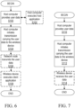
- FIG. 7 is a flowchart illustrating an example method implemented in a communication system, such as, for example, the communication system of FIG. 4 , in accordance with one embodiment.
- the communication system may include a host computer 24, a network node 16 and a WD 22, which may be those described with reference to FIGS. 4 and 5 .
- the host computer 24 provides user data (Block S110).
- the host computer 24 provides the user data by executing a host application, such as, for example, the host application 50.
- the host computer 24 initiates a transmission carrying the user data to the WD 22 (Block S112).
- the transmission may pass via the network node 16, in accordance with the teachings of the embodiments described throughout this disclosure.
- the WD 22 receives the user data carried in the transmission (Block S114).
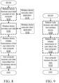
- FIG. 8 is a flowchart illustrating an example method implemented in a communication system, such as, for example, the communication system of FIG. 4 , in accordance with one embodiment.
- the communication system may include a host computer 24, a network node 16 and a WD 22, which may be those described with reference to FIGS. 4 and 5 .
- the WD 22 receives input data provided by the host computer 24 (Block S116).
- the WD 22 executes the client application 92, which provides the user data in reaction to the received input data provided by the host computer 24 (Block S118). Additionally or alternatively, in an optional second step, the WD 22 provides user data (Block S120).
- the WD provides the user data by executing a client application, such as, for example, client application 92 (Block S122).
- client application 92 may further consider user input received from the user.
- the WD 22 may initiate, in an optional third substep, transmission of the user data to the host computer 24 (Block S124).
- the host computer 24 receives the user data transmitted from the WD 22, in accordance with the teachings of the embodiments described throughout this disclosure (Block S126).
- FIG. 9 is a flowchart illustrating an example method implemented in a communication system, such as, for example, the communication system of FIG. 4 , in accordance with one embodiment.
- the communication system may include a host computer 24, a network node 16 and a WD 22, which may be those described with reference to FIGS. 4 and 5 .
- the network node 16 receives user data from the WD 22 (Block S128).
- the network node 16 initiates transmission of the received user data to the host computer 24 (Block S130).
- the host computer 24 receives the user data carried in the transmission initiated by the network node 16 (Block S132).
- FIG. 10 is a flowchart of a method in a network node 16 according to the claimed embodiment.
- One or more blocks described herein may be performed by one or more elements of network node 16 such as by one or more of processing circuitry 68 (including the configuration unit 32), processor 70, radio interface 62 and/or communication interface 60.
- Network node 16 is configured to configure (Block S134) a first measurement resource for channel measurements, as described herein.
- Network node 16 is configured to configure (Block S136) a second measurement resource for interference measurements, as described herein.
- Network node 16 is configured to cause (Block S138) transmission of a first signal with a first predefined power level in a transmission occasion of the first measurement resource, as described herein.
- Network node 16 is configured to cause (Block S140) transmission of a second signal with a second predefined power level in a transmission occasion of the second measurement resource where at least one of the first predefined power level and the second predefined power level is configured to at least in part mitigate channel quality indication, CQI, saturation, as described herein.
- the first measurement resource is a non-zero power channel state information-reference signal, NZP CSI-RS, resource.
- the second measurement resource is a channel state information-interference measurement, CSI-IM, resource.
- the second measurement resource is a non-zero power channel state information-reference signal, NZP CSI-RS, resource.
- the processing circuitry is further configured to cause transmission of a third signal with a third predefined power level in another transmission occasion of the second measurement resource, receive a first reported CQI associated with the second signal, and receive a second reported CQI associated with the third signal, the first reported CQI being different than the second reported CQI.
- the processing circuitry is further configured to estimate a signal to interference plus noise ratio, SINR, based on at least one of the first reported CQI and second reported CQI, and perform at least one action based at least in part on the estimated SINR.
- SINR signal to interference plus noise ratio
- the processing circuitry is further configured to receive a first reported CQI associated with the first signal and the second signal, estimate a signal to interference plus noise ratio, SINR, based on the first reported CQI, and perform at least one action based at least in part on the estimated SINR.
- the at least one action includes performing at least one of link adaptation and a modulation and coding rate decision.
- the at least one of the first predefined power level and second predefined power level is configured to at least in part mitigate CQI saturation by causing a signal to interference plus noise ratio, SINR, observed by a wireless device 22 to change, the observed SINR mapping to a reportable CQI.
- the at least in part mitigating of CQI saturation corresponds to causing a reportable CQI to change from saturated CQI to non-saturated CQI by changing a signal to interference plus noise ratio, SINR, observed by the wireless device 22.
- the processing circuitry is further configured to configure a third measurement resource for interference measurements, cause transmission of a third signal with a third predefined power level in a transmission occasion of the third measurement resource, and at least one of the first predefined power level where the second predefined power level and the third predefined power level is configured to at least in part mitigate channel quality indication, CQI, saturation.
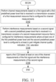
- FIG. 11 is a flowchart of a method in a wireless device 22 according to the claimed embodiment, One or more blocks described herein may be performed by one or more elements of wireless device 22 such as by one or more of processing circuitry 84 (including the CQI unit 34), processor 86, radio interface 82 and/or communication interface 60.
- Wireless device 22 is configured to perform (Block S142) channel measurements based on a first signal with a first predefined power level that is received in a transmission occasion of a first measurement resource that is configured for channel measurements, as described herein.
- Wireless device 22 is configured to perform (Block S144) interference measurements based on a second signal with a second predefined power level that is received in a transmission occasion of a second measurement resource that is configured for interference measurements where at least one of the first predefined power level and the second predefined power level is configured to at least in part mitigate channel quality indication, CQI, saturation, as described herein.
- Wireless device 22 is configured to report (Block S146) a first CQI based at least on one of the channel measurements of the first signal and the interference measurements of the second signal, as described herein.
- the first measurement resource is a non-zero power channel state information reference signal, NZP CSI-RS, resource.
- the second measurement resource is a channel state information-interference measurement, CSI-IM, resource.
- the second measurement resource is a non-zero power channel state information reference signal, NZP CSI-RS, resource.
- the processing circuitry is further configured to perform interference measurements based on a third signal with a third predefined power level that is received in another transmission occasion of the second measurement resource that is configured for interference measurements, and report a second CQI associated with the interference measurements of the third signal where the first CQI is a different than the second CQI and is associated with the interference measurements of the second signal.
- the processing circuitry is further configured to observe CQI that has been changed by the at least one of the first predefined power level and second predefined power level for at least in part mitigating CQI saturation.
- the at least in part mitigating of CQI saturation corresponds to reporting a CQI that has changed from saturated CQI to a non-saturated CQI.
- the processing circuitry is further configured to perform interference measurements based on a third signal with a third predefined power level that is received in a transmission occasion of a third measurement resource that is configured for interference measurements, and where at least one of the first predefined power level, the second predefined power level and the third predefined power level is configured to at least in part mitigate channel quality indication, CQI, saturation, as described herein.
- Network node 16 functionality described below may be performed by at least one of processing circuitry 68, radio interface 62, processor 70, configuration unit 32, etc.
- Wireless device 22 functionality described below may be performed by at least one of processing circuitry 84, processor 86, radio interface 82, CQI unit 34, etc.
- one NZP CSI-RS resource for channel measurement and one CSI-IM resource for interference measurement is configured.
- a signal with a transmission power is transmitted where the transmission power is non-zero. The transmission power is adjusted to control the wireless device 22 observed SINR, thus change/modifying the wireless device 22 reported CQI.
- a signal with a first transmission power is transmitted
- a signal with a second transmission power level is transmitted so that wireless device 22 can provide two or more kinds of feedbacks
- each report is with different SINR where some report(s) may be with a higher SINR, and some report(s) with lower SINR, while a time restrictions for interference measurements may be configured (i.e., configuring "timeRestrictionForInterferenceMeasurements" to avoid the wireless device 22 from performing any interference average across time.
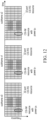
- one 32-port CSI-RS resource for channel measurements is configured, marked as blocks with one style of hatching or fill pattern
- one CSI-IM resource for interference measurements is configured, marked as blocks with another style of hatching or fill pattern.
- transmission power p 0 is transmitted on CSI-IM
- transmission power p 1 , ..., p n are applied, respectively, where n is any integer number larger than 1.
- the pattern can be repetitive with a periodicity.
- the power allocation pattern for CSI-IM could be p 0 , p 1 , p 0 , p 1 , ⁇ , p 0 , p 1 .
- the power allocation pattern for CSI-IM could be p 0 , p 0 , ⁇ , p 0 .
- the wireless device 22 can use the CSI-RS for channel measurements to acquire the channel and use CSI-IM to measure interference and noise, and further derive CQI based on the measured channel and measured the interference and noise.
- matrix P is with dimension nPorts x nLayers
- W p 2 a csirs is with dimension nTx x nPorts
- H is with dimension nRx x nTx.
- SINR trace P H W p 2 a csirs H H HW p 2 a csirs P p k ⁇ trace W p 2 a csiim H H H HW p 2 a csiim + I
- adjusting p k can adjust the SINR value, thus further adjust feedback CQI. Setting a proper value for p k can avoid the CQI saturation.
- network node 16 can estimate the SINR and further estimate the I since all the parameters are known except I .
- I trace P H W p 2 a csirs H H HW p 2 a csirs P g CQI ⁇ p k ⁇ trace W p 2 a csiim H H H HW p 2 a csiim
- g(-) is a function to predict SINR based on CQI report.
- SINR_CQI * (CSI_IM/I+ 1)
- network node 16 is configured to configure (Block S148) one CSI-RS source for channel measurement and one CSI-IM resource for interference measurement, as described herein.
- Network node 16 is configured to cause (Block S150) transmission of a signal with a transmission power p on CSI-IM, as described herein.
- Wireless device 22 is configured to estimate (Block S152) CQI based on CSI-RS and CSI-IM considering the transmitted signal on the CSI-IM and interference signal on REs of CSI-IM, as described herein.
- Wireless device 22 is configured to feedback (Block S154) the CQI, as described herein.
- the network node 16 is configured to estimate (Block S156) an interference signal on REs of CSI-IM by removing the transmitted signal impact based on the CQI report, as described herein.
- the network node 16 is configured to perform (Block S158) link adaptation based on the estimated interference signal on RES of CSI-IM, as described herein.
- network node 16 may set the transmission power in subframe 1 to zero.
- Network node 16 may further, in the case where a non-zero transmission power p n was injected in subframe n and the corresponding reported CQI still was saturated, inject a larger transmission power in subframe n+1 and continue to increase the transmission power injected on CSI-IM resources on subsequent subframes as long as the CQI is saturated.
- the beam ( W p 2 a csiim ) of the CSI-IM can be wide and non- wireless device 22 specific or be narrow and wireless device-specific.
- wide beam for CSI-IM it allows wireless devices 22 in the cell to use the same CSI-IM signal to derive CQI.
- narrow beam for CSI-IM there is a benefit in that it allows wireless devices 22 to measure potential interference from a certain Tx direction. By sweeping the narrow CSI-IM beams, as the CQI saturation issue is alleviated, network node 16 may also obtain measurements of interference from interested Tx directions.
- the method includes configuring one CSI-RS resource for channel measurements and two or more CSI-IM resources for interference measurements.
- a signal with the first transmission power is transmitted in a first CSI-IM resource.
- a signal with a second transmission power is transmitted in a second CSI-IM resource.
- Multiple trigger states are defined for CSI report. At least one trigger state is associated with the report with the first CSI-IM resource and another trigger state is associated with the report with the second CSI-IM resource.
- multiple CQIs can be reported by wireless device 22 by triggering different trigger states at different time occasions.
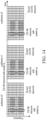
- one 32-port CSI-RS resource for channel measurements is configured, marked as blocks with a particular hatching or filled pattern style, two CSI-IM resources for interference measurements, wherein the first CSI-IM resource is marked with another hatching or fill pattern style and the second CSI-IM resource is marked with yet another hatching or fill pattern style.
- the signal with transmission power p 0 is transmitted
- the signal with transmission p 1 is transmitted.
- p 0 can be set to zero and p 1 can be set into a non-zero value.
- the first CSI-IM can be used to avoid low-SNR saturation issue, and the second CSI-IM can be used for high-SNR saturation issue.
- CSI trigger states, CSI-RS resource sets and CSI report setting may be taken into account and particularly designed.
- a wireless device 22 is configured by higher layers with N ⁇ 1 CSI-ReportConfig Reporting Settings, M ⁇ 1 CSI-ResourceConfig Resource Settings, and one or two list(s) of trigger states (given by the higher layer parameters CSI-AperiodicTriggerStateList and CSI-SemiPersistentOnPUSCH-TriggerStateList).
- Each trigger state in CSI-AperiodicTriggerStateList contains a list of associated CSI-ReportConfigs indicating the Resource Set IDs for channel and optionally for interference.
- a single set of CSI triggering states are higher layer configured.
- a trigger state is initiated using the CSI request field in DCI.
- CSI-AperiodicTriggerStateList if a Resource Setting linked to a CSI-ReportConfig has multiple aperiodic resource sets, only one of the aperiodic CSI-RS resource sets from the Resource Setting is associated with the trigger state, and the wireless device 22 is higher layer configured per trigger state per Resource Setting to select the one CSI-IM/NZP CSI-RS resource set from the Resource Setting.
- one CSI-ReportConfig can be defined.
- the CSI-ReportConfig it associates the CSI report with a plurality of CSI-ResourceConfig Resource Settings.
- the CSI-ResourceConfig Resource Setting one NZP-CSI-RS-Resource set (NZP-CSI-RS-ResourceSet#0) for channel measurements and two csi-IM-ResourceSets (csi-IM-ResourceSet#0 and CSI-IM-ResourceSet#1) for interference measurements are defined.
- TriggerState#0 is used to select NZP-CSI-RS-ResourceSet#0 for channel measurements and csi-IM-ResourceSet#0 for interference measurements
- TriggerState#1 is used to select NZP-CSI-RS-ResourceSet#0 for channel measurements and csi-IM-ResourceSet#1 for interference measurements.
- TriggerState#0 is initiated using DCI in one downlink slot
- TriggerState#1 is initiated using DCI in another downlink slot.
- SINR 0 trace P H W p 2 a csirs H H HW p 2 a csirs P p 0 ⁇ trace W p 2 a csiim H H H HW p 2 a csiim + I ,
- SINR 1 trace P H W p 2 a csirs H H HW p 2 a csirs P p 1 ⁇ trace W p 2 a csiim H H H HW p 2 a csiim + I ,
- SINR 0 can be used for SU-MIMO link adaptation, or used to avoid the lower SINR saturation issue
- SINR 1 can be used for MU-MIMO link adaptation or used to avoid the higher SINR saturation issue.
- two aperiodic CSI Report Settings are configured and mapped to individual trigger states.
- the first CSI Report Setting is associated with one periodic NZP CSI-RS resource for channel measurement and one periodic CSI-IM resource for interference measurement, where a first transmission power (which may typically be equal to zero) is injected on the periodic CSI-IM resource. Since these resources are periodic, they are transmitted with a certain periodicity and slot offset.
- the second CSI Report Setting is associated with one aperiodic NZP CSI-RS resource for channel measurement and one aperiodic CSI-IM resource for interference measurement, where a second transmission power (which may typically be larger than zero) is injected on the aperiodic CSI-IM resource.
- the aperiodic CSI-RS resource is configured to occupy the same resource element within a slot as the periodic CSI-RS resource while the aperiodic CSI-IM resource do not occupy the same resource elements as the periodic CSI-IM resource. Since these resources are aperiodic, they are only present from a wireless device 22 perspective in the slot wherein the triggering DCI is transmitted.
- network node 16 can trigger the second CSI Report Setting in the same slot wherein an occasion of the periodic CSI-RS resource is present.
- the periodic and aperiodic CSI-RS resource will thus "overlap" from wireless device 22 perspective, implying that network node 16 only needs to transmit one CSI-RS resource which reduces CSI-RS overhead.
- one CSI-RS resource for channel measrurements and one nzp-CSI-RS-Resource for interfernece measurements are configured.
- For the power transmission for the nzp-CSI-RS-ResourceForInterference there are two alternatives.
- a fixed transmission power is used for nzp-CSI-RS-ResourceForInterference. The power is determined so that the wireless device 22's CQI is not saturated.
- the transmission power for nzp-CSI-RS-ResourceForInterference is fixed, and a different wireless device 22 may use different powerControlOffset. For cell-center wireless device 22, larger powerControlOffset may be informed, and for cell-edge wireless device 22, smaller powerControlOffset may be informed.
- different transmission power is applied for the nzp-CSI-RS-Resource for interference measurements over time. More specifically, in a first nzp-CSI-RS-ResourcesForInterference resource transmission occasion, a signal with a first transmission power is transmitted, whereas in a second nzp-CSI-RS-ResourcesForInterference resource transmission occasion, a signal with a second transmission power level is transmitted, so that the wireless device 22 can provide two or more kinds of feedbacks, each report is with different SINR, some is with higher SINR and some is with lower SINR. In order to avoid wireless device 22 to perform any interference average across time, where a time restriction for interference measurements is configured, i.e., "timeRestrictionForInterferenceMeasurements" is configured.
- the SINR range can be controlled, thus control the CQI range.
- nzp-CSI-RS-ResourceForInterference signal with the first transmission power is transmitted.
- a second nzp-CSI-RS-ResourceForInterference a signal with a second transmission power is transmitted, so that the wireless device 22 can feedback a plurality of feedback where each feedback is associated with a different SINR, thus the CQI saturation issue can be eliminated.
- same REs and same transmission power is applied to two nzp-CSI-RS-ResourcesForInterference, but different powerControlOffset is associated with nzp-CSI-RS-ResourcesForInterference.
- powerControlOffset is not necessarily equal to the transmission power and may only be used for CSI calculation. Since the same REs are used, although two nzp-CSI-RS-ResourcesForInterference are configured, the overhead to transmit two nzp-CSI-RS-ResourcesForInterference is the same as that for one nzp-CSI-RS-ResourceForInterference. As a result, the CSI-RS overhead is reduced.
- NZP-CSI-RS-ResourceSet#0 one NZP-CSI-RS-Resource set for channel measurements and two sets of nzp-CSI-RS-ResourcesForInterference (nzp-CSI-RS-ResourcesForInterference#0 and nzp-CSI - RS- ResourcesFor Interference# 1) are defined.
- TriggerState#0 is used to select NZP-CSI-RS-ResourceSet#0 for channel measurements and nzp-CSI-RS-ResourcesForInterference#0 for interference measurements
- TriggerState#1 is used to select NZP-CSI-RS-ResourceSet#0 for channel measurements and nzp-CSI-RS-ResourcesForInterference#1 for interference measurements.
- TriggerState#0 is initiated using downlink control information (DCI) in one downlink slot
- TriggerState#1 is initiated using DCI in another downlink slot.
- DCI downlink control information
- SINR trace P H W p 2 a csirs H H HW p 2 a csirs P p 0 ⁇ trace W p 2 a nzp _ inter H H H HW p 2 a nzp _ inter + I ,
- SINR trace P H W p 2 a csirs H H HW p 2 a csirs P p 1 ⁇ trace W p 2 a nzp _ inter H H HW p 2 a nzp _ inter + I , where W p 2 a nzp _ inter is the port to antenna mapping for nzp-CSI-RS-ResourcesForInterference.
- W p 0 and p 1 are the actual transmitted power for nzp-CSI-RS-ResourcesForInterference.
- p 0 and p 1 are the powerControlOffset for the first and second set of nzp-CSI-RS-Resources For Interference.
- network node 16 upon checking the wireless device 22 CQI report, if the CQI report is larger than a first threshold for a first time-duration, network node 16 uses RRC to configure the first powerControlOffset for the CSI-RS resource for channel measurements for the given wireless device 22. Otherwise, network node 16 uses RRC to configure the second powerControlOffset for the CSI resource for channel measurements, so that wireless device 22 can have different back off for the CQI report. Thus, the CQI saturation issues can be mitigated.
- At least some of the above-mentioned embodiments can be combined to mitigate the CQI saturation issue.
- the following are configured: one CSI-RS resource for channel measurements, one csi-IM-ResourcesForInterference, and two nzp-CSI-RS-ResourcesForInterference. These two nzp-CSI-RS-ResourcesForInterference can be with different transmission power or different powerControlOffset.
- the following are configured: one CSI-RS resource for channel measurements, two csi-IM-ResourcesForInterference, and one nzp-CSI-RS-ResourcesForInterference. These two csi-IM-ResourcesForInterference can be with different transmission power.
- One or more embodiments described herein may be applied to TDD systems.
- One or more embodiments described herein that, for example, use RRC to reconfigure the offset may be applied to TDD and/or FDD systems.
- the concepts described herein may be embodied as a method, data processing system, computer program product and/or computer storage media storing an executable computer program. Accordingly, the concepts described herein may take the form of an entirely hardware embodiment, an entirely software embodiment or an embodiment combining software and hardware aspects all generally referred to herein as a "circuit" or “module.” Any process, step, action and/or functionality described herein may be performed by, and/or associated to, a corresponding module, which may be implemented in software and/or firmware and/or hardware. Furthermore, the disclosure may take the form of a computer program product on a tangible computer usable storage medium having computer program code embodied in the medium that can be executed by a computer. Any suitable tangible computer readable medium may be utilized including hard disks, CD-ROMs, electronic storage devices, optical storage devices, or magnetic storage devices.
- These computer program instructions may also be stored in a computer readable memory or storage medium that can direct a computer or other programmable data processing apparatus to function in a particular manner, such that the instructions stored in the computer readable memory produce an article of manufacture including instruction means which implement the function/act specified in the flowchart and/or block diagram block or blocks.
- the computer program instructions may also be loaded onto a computer or other programmable data processing apparatus to cause a series of operational steps to be performed on the computer or other programmable apparatus to produce a computer implemented process such that the instructions which execute on the computer or other programmable apparatus provide steps for implementing the functions/acts specified in the flowchart and/or block diagram block or blocks.
- Computer program code for carrying out operations of the concepts described herein may be written in an object oriented programming language such as Python, Java ® or C++.
- the computer program code for carrying out operations of the disclosure may also be written in conventional procedural programming languages, such as the "C" programming language.
- the program code may execute entirely on the user's computer, partly on the user's computer, as a stand-alone software package, partly on the user's computer and partly on a remote computer or entirely on the remote computer.
- the remote computer may be connected to the user's computer through a local area network (LAN) or a wide area network (WAN), or the connection may be made to an external computer (for example, through the Internet using an Internet Service Provider).
- LAN local area network
- WAN wide area network
- Internet Service Provider for example, AT&T, MCI, Sprint, EarthLink, MSN, GTE, etc.
Landscapes
- Engineering & Computer Science (AREA)
- Computer Networks & Wireless Communication (AREA)
- Signal Processing (AREA)
- Quality & Reliability (AREA)
- Mobile Radio Communication Systems (AREA)
Claims (14)
- Verfahren, das von Netzwerkknoten (16) implementiert wird, der zum Kommunizieren mit einer drahtlosen Vorrichtung (22) konfiguriert ist, wobei das Verfahren umfasst:Konfigurieren (S134) einer ersten Messressource für Kanalmessungen;Konfigurieren (S136) einer zweiten Messressource für Interferenzmessungen;Veranlassen (S138) von Übertragung eines ersten Signals mit einem ersten vordefinierten Leistungspegel bei einer Übertragungsgelegenheit der ersten Messressource; undVeranlassen (S140) von Übertragung eines zweiten Signals mit einem zweiten vordefinierten Leistungspegel bei einer Übertragungsgelegenheit der zweiten Messressource, wobei mindestens einer von dem ersten vordefinierten Leistungspegel und dem zweiten vordefinierten Leistungspegel so konfiguriert ist, dass er Kanalqualitätsanzeigesättigung, CQI-Sättigung, zumindest teilweise mindert, wobei das zumindest teilweise Mindern der CQI-Sättigung einem Veranlassen einer Änderung einer meldepflichtigen CQI von einer gesättigten CQI in eine ungesättigte CQI durch Ändern eines Signal-zu-Interferenz-plus-Rausch-Verhältnisses, SINR, entspricht, das von der drahtlosen Vorrichtung (22) beobachtet und der meldepflichtigen CQI zugeordnet wird,wobei die meldepflichtige CQI gesättigt ist, wenn sie einem höchsten Wert einer meldepflichtigen CQI entspricht.
- Verfahren nach Anspruch 1, wobei die erste Messressource eine Ressource für ein Kanalzustandsinformations-Referenzsignal mit einer von null verschiedenen Leistung, NZP-CSI-RS-Ressource, ist.
- Verfahren nach einem der Ansprüche 1 bis 2, wobeii) die zweite Messressource eine Kanalzustandsinformations-Interferenzmessressource, CSI-IM-Ressource, ist; oderii) die zweite Messressource eine Ressource für ein Kanalzustandsinformations-Referenzsignal mit einer von null verschiedenen Leistung, NZP-CSI-RS-Ressource, ist.
- Verfahren nach einem der Ansprüche 1 bis 3, ferner umfassend:Veranlassen von Übertragung eines dritten Signals mit einem dritten vordefinierten Leistungspegel bei einer anderen Übertragungsgelegenheit der zweiten Messressource;Empfangen einer ersten meldepflichtigen CQI, die mit dem zweiten Signal assoziiert ist;Empfangen einer zweiten meldepflichtigen CQI, die mit dem dritten Signal assoziiert ist, wobei die erste meldepflichtigen CQI eine andere als die zweite meldepflichtige CQI ist;Schätzen eines Signal-zu-Interferenz-plus-Rausch-Verhältnisses, SINR, basierend auf mindestens einer von der ersten meldepflichtigen CQI und der zweiten meldepflichtigen CQI; undDurchführen mindestens einer Aktion wenigstens zum Teil basierend auf dem geschätzten SINR.
- Verfahren nach einem der Ansprüche 1 bis 3, ferner umfassend:Empfangen einer ersten meldepflichtigen CQI, die mit dem ersten Signal und dem zweiten Signal assoziiert ist;Schätzen eines Signal-zu-Interferenz-plus-Rausch-Verhältnisses, SINR, basierend auf der ersten meldepflichtigen CQI; undDurchführen mindestens einer Aktion wenigstens zum Teil basierend auf dem geschätzten SINR; und optionalwobei die mindestens eine Aktion ein Durchführen mindestens einer von einer Verbindungsanpassung und einer Entscheidung hinsichtlich einer Modulations- und Codierungsrate umfasst.
- Verfahren nach Anspruch 1, ferner umfassend:Konfigurieren einer dritten Messressource für Interferenzmessungen;Veranlassen von Übertragung eines dritten Signals mit einem dritten vordefinierten Leistungspegel bei einer Übertragungsgelegenheit der dritten Messressource; undwobei mindestens einer von dem ersten vordefinierten Leitungspegel, dem zweiten vordefinierten Leistungspegel und dem dritten vordefinierten Leistungspegel so konfiguriert ist, dass er Kanalqualitätsanzeigesättigung, CQI-Sättigung, zumindest teilweise mindert.
- Verfahren, das von einer drahtlosen Vorrichtung (22) implementiert wird, die zum Kommunizieren mit einem Netzwerkknoten (16) konfiguriert ist, wobei das Verfahren umfasst:Durchführen (S142) von Kanalmessungen basierend auf einem ersten Signal mit einem ersten vordefinierten Leistungspegel, das bei einer Übertragungsgelegenheit einer ersten Messressource empfangen wird, die für Kanalmessungen konfiguriert ist;Durchführen (S144) von Interferenzmessungen basierend auf einem zweiten Signal mit einem zweiten vordefinierten Leistungspegel, das bei einer Übertragungsgelegenheit einer zweiten Messressource empfangen wird, die für Interferenzmessungen konfiguriert ist, wobei mindestens einer von dem ersten vordefinierten Leistungspegel und dem zweiten vordefinierten Leistungspegel so konfiguriert ist, dass er Kanalqualitätsanzeigesättigung, CQI-Sättigung, zumindest teilweise mindert, wobei das zumindest teilweise Mindern der CQI-Sättigung einem Melden einer meldepflichtigen CQI entspricht, die sich von einer gesättigten CQI in eine ungesättigte CQI geändert hat, undwobei die meldepflichtige CQI gesättigt ist, wenn sie einem höchsten Wert einer meldepflichtigen CQI entspricht; undMelden (S146) der meldepflichtigen CQI basierend auf mindestens einer von den Kanalmessungen des ersten Signals und den Interferenzmessungen des zweiten Signals.
- Verfahren nach Anspruch 7, wobei die erste Messressource eine Ressource für ein Kanalzustandsinformations-Referenzsignal mit einer von null verschiedenen Leistung, NZP-CSI-RS-Ressource, ist.
- Verfahren nach einem der Ansprüche 7 bis 8, wobeii) die zweite Messressource eine Kanalzustandsinformations-Interferenzmessressource, CSI-IM-Ressource, ist; oderii) die zweite Messressource eine Ressource für ein Kanalzustandsinformations-Referenzsignal mit einer von null verschiedenen Leistung, NZP-CSI-RS-Ressource, ist.
- Verfahren nach einem der Ansprüche 7 bis 9, ferner umfassend:Durchführen von Interferenzmessungen basierend auf einem dritten Signal mit einem dritten vordefinierten Leistungspegel, das bei einer anderen Übertragungsgelegenheit der zweiten Messressource empfangen wird, die für Interferenzmessungen konfiguriert ist; undMelden einer zweiten CQI, die mit den Interferenzmessungen des dritten Signals assoziiert ist, wobei die erste CQI eine andere als die zweite CQI und mit den Interferenzmessungen des zweiten Signals assoziiert ist.
- Verfahren nach einem der Ansprüche 7 bis 10, ferner umfassend ein Beobachten der CQI, die durch den mindestens einen von dem ersten vordefinierten Leistungspegel und dem zweiten vordefinierten Leistungspegel geändert wurde, um CQI-Sättigung zumindest teilweise zu mindern.
- Verfahren nach Anspruch 7, ferner umfassend:Durchführen von Interferenzmessungen basierend auf einem dritten Signal mit einem dritten vordefinierten Leistungspegel, das bei einer Übertragungsgelegenheit einer dritten Messressource empfangen wird, die für Interferenzmessungen konfiguriert ist; undwobei mindestens einer von dem ersten vordefinierten Leitungspegel, dem zweiten vordefinierten Leistungspegel und dem dritten vordefinierten Leistungspegel so konfiguriert ist, dass er Kanalqualitätsanzeigesättigung, CQI-Sättigung, zumindest teilweise mindert.
- Netzwerkknoten (16), konfiguriert zum Kommunizieren mit einer drahtlosen Vorrichtung, WD, (22), wobei der Netzwerkknoten (16) Folgendes umfasst:
Verarbeitungsschaltungsanordnung (68), die konfiguriert ist zum:
Durchführen des Verfahrens einem nach der Ansprüche 1 bis 6. - Drahtlose Vorrichtung (22), konfiguriert zum Kommunizieren mit einem Netzwerkknoten (16), wobei die drahtlose Vorrichtung (22) umfasst:
Verarbeitungsschaltungsanordnung (84), die konfiguriert ist zum:
Durchführen des Verfahrens nach einem der Ansprüche 7 bis 12.
Applications Claiming Priority (2)
| Application Number | Priority Date | Filing Date | Title |
|---|---|---|---|
| US202063002624P | 2020-03-31 | 2020-03-31 | |
| PCT/IB2021/052657 WO2021198928A1 (en) | 2020-03-31 | 2021-03-30 | Channel quality indication (cqi) saturation mitigation |
Publications (2)
| Publication Number | Publication Date |
|---|---|
| EP4128560A1 EP4128560A1 (de) | 2023-02-08 |
| EP4128560B1 true EP4128560B1 (de) | 2024-11-13 |
Family
ID=75439147
Family Applications (1)
| Application Number | Title | Priority Date | Filing Date |
|---|---|---|---|
| EP21717540.5A Active EP4128560B1 (de) | 2020-03-31 | 2021-03-30 | Sättigungsabschwächung einer kanalqualitätsanzeige (cqi) |
Country Status (3)
| Country | Link |
|---|---|
| US (1) | US11968016B2 (de) |
| EP (1) | EP4128560B1 (de) |
| WO (1) | WO2021198928A1 (de) |
Families Citing this family (9)
| Publication number | Priority date | Publication date | Assignee | Title |
|---|---|---|---|---|
| EP4128560B1 (de) * | 2020-03-31 | 2024-11-13 | Telefonaktiebolaget LM Ericsson (publ.) | Sättigungsabschwächung einer kanalqualitätsanzeige (cqi) |
| US12082032B2 (en) | 2020-09-15 | 2024-09-03 | Apple Inc. | Reporting interference and noise power fluctuations |
| CN116195293B (zh) * | 2020-09-15 | 2025-04-25 | 苹果公司 | 从用户装备接收干扰和噪声功率波动报告 |
| US20220295498A1 (en) * | 2021-03-15 | 2022-09-15 | Samsung Electronics Co., Ltd. | Method and apparatus for aperiodic csi measurement and reporting |
| WO2023117152A1 (en) * | 2021-12-22 | 2023-06-29 | Telefonaktiebolaget Lm Ericsson (Publ) | Interference measurement technique |
| KR20230150671A (ko) * | 2022-04-22 | 2023-10-31 | 삼성전자주식회사 | 무선 통신 시스템의 전력 절감을 위한 방법 및 장치 |
| US12362883B2 (en) * | 2022-06-30 | 2025-07-15 | Qualcomm Incorporated | Channel state information processing parameters for dynamic network entity power adaptation |
| WO2024168757A1 (zh) * | 2023-02-16 | 2024-08-22 | 富士通株式会社 | 信道质量指示的计算和指示方法以及装置 |
| CN120956382A (zh) * | 2024-04-03 | 2025-11-14 | 维沃移动通信有限公司 | 尾码传输方法和设备 |
Family Cites Families (27)
| Publication number | Priority date | Publication date | Assignee | Title |
|---|---|---|---|---|
| WO2010048471A1 (en) | 2008-10-24 | 2010-04-29 | Interdigital Patent Holdings, Inc. | Method and apparatus for temperature control in a wireless terminal |
| US8903327B2 (en) * | 2011-09-15 | 2014-12-02 | Qualcomm Incorporated | Channel quality reporting using a dynamically adjusted measurement power offset |
| CN102546110A (zh) * | 2011-12-31 | 2012-07-04 | 电信科学技术研究院 | 一种传输信道状态信息的方法及装置 |
| US9008585B2 (en) * | 2012-01-30 | 2015-04-14 | Futurewei Technologies, Inc. | System and method for wireless communications measurements and CSI feedback |
| WO2013143069A1 (en) * | 2012-03-27 | 2013-10-03 | Nec (China) Co., Ltd. | Method and apparatus for outer loop link adaptation for a wireless communication system |
| US9537638B2 (en) * | 2012-05-11 | 2017-01-03 | Qualcomm Incorporated | Method and apparatus for performing coordinated multipoint feedback under multiple channel and interference assumptions |
| US10945270B2 (en) * | 2012-09-27 | 2021-03-09 | Futurewei Technologies, Inc. | System and method for configuring channel state information in a communications system |
| US9306725B2 (en) * | 2013-03-13 | 2016-04-05 | Samsung Electronics Co., Ltd. | Channel state information for adaptively configured TDD communication systems |
| CN103857054B (zh) * | 2014-03-12 | 2017-06-20 | 天津大学 | 长期演进系统媒体访问控制层中复用与调度联合处理方法 |
| US20150263796A1 (en) * | 2014-03-14 | 2015-09-17 | Samsung Electronics Co., Ltd. | Channel state information for reporting an advanced wireless communications system |
| CN106797649B (zh) * | 2014-10-10 | 2021-06-04 | 瑞典爱立信有限公司 | 与灵活的csi配置和关联反馈有关的系统和方法 |
| US20160149679A1 (en) * | 2014-10-10 | 2016-05-26 | Telefonaktiebolaget L M Ericsson (Publ) | Method for dynamic csi feedback |
| JP6604378B2 (ja) * | 2014-10-27 | 2019-11-13 | 華為技術有限公司 | 適応変調コーディングの方法および装置 |
| CN107113635B (zh) | 2014-12-17 | 2020-02-14 | 华为技术有限公司 | 用于确定小区状态以调整天线配置参数的方法和装置 |
| US20160277942A1 (en) * | 2015-03-17 | 2016-09-22 | Qualcomm Incorporated | Load-aware channel state reference signal transmission |
| WO2018064812A1 (en) * | 2016-10-08 | 2018-04-12 | Huawei Technologies Co., Ltd. | System and method for pilot data detection using correlation peak tracking |
| CN108810932A (zh) * | 2017-05-05 | 2018-11-13 | 华为技术有限公司 | 信道状态信息处理方法及其装置 |
| EP4099603B1 (de) * | 2017-05-05 | 2023-12-20 | Telefonaktiebolaget Lm Ericsson (Publ) | Interferenzmessungen und kanalzustandsinformationsrückkopplung für mehrbenutzer-mimo |
| WO2018227391A1 (en) * | 2017-06-13 | 2018-12-20 | Nec Corporation | Methods, terminal device, network devices and apparatuses for interference measurement |
| CN111434069B (zh) * | 2017-10-02 | 2023-06-13 | 瑞典爱立信有限公司 | 采用nzp csi-rs的mu干扰测量的方法、用户设备和基站 |
| US10651900B2 (en) * | 2018-05-18 | 2020-05-12 | Futurewei Technologies, Inc. | System and method for communications system training |
| US12081297B2 (en) * | 2018-08-08 | 2024-09-03 | Lg Electronics Inc. | Method for transmitting or receiving channel state information for plurality of base stations in wireless communication system, and device therefor |
| EP3841706A1 (de) | 2018-08-20 | 2021-06-30 | Telefonaktiebolaget Lm Ericsson (Publ) | Verbesserung des immunsystems von orten unter verwendung generativer kontradiktorischer netzwerke und verstärkungslernen |
| EP3928466A1 (de) | 2019-02-20 | 2021-12-29 | Telefonaktiebolaget Lm Ericsson (Publ) | Justierausrichtung für mikrowellenübertragungen basierend auf einem rl-modell |
| EP4000195B1 (de) * | 2019-07-18 | 2024-01-10 | Telefonaktiebolaget LM Ericsson (publ) | Cqi-sättigungsabschwächung in massiven mu-mimo-systemen |
| EP4055768A4 (de) * | 2019-11-07 | 2023-01-04 | Guangdong Oppo Mobile Telecommunications Corp., Ltd. | Kommunikationsverfahren und -vorrichtung |
| EP4128560B1 (de) * | 2020-03-31 | 2024-11-13 | Telefonaktiebolaget LM Ericsson (publ.) | Sättigungsabschwächung einer kanalqualitätsanzeige (cqi) |
-
2021
- 2021-03-30 EP EP21717540.5A patent/EP4128560B1/de active Active
- 2021-03-30 US US17/915,304 patent/US11968016B2/en active Active
- 2021-03-30 WO PCT/IB2021/052657 patent/WO2021198928A1/en not_active Ceased
Also Published As
| Publication number | Publication date |
|---|---|
| US11968016B2 (en) | 2024-04-23 |
| US20230122910A1 (en) | 2023-04-20 |
| WO2021198928A1 (en) | 2021-10-07 |
| EP4128560A1 (de) | 2023-02-08 |
Similar Documents
| Publication | Publication Date | Title |
|---|---|---|
| EP4128560B1 (de) | Sättigungsabschwächung einer kanalqualitätsanzeige (cqi) | |
| US10158465B2 (en) | Method for transceiving signal in wireless communication system and apparatus therefor | |
| US20200389883A1 (en) | Configuring spatial qcl reference in a tci state | |
| US9794014B2 (en) | Method for receiving signal using interference removal scheme and apparatus for same in wireless communication system | |
| US9967013B2 (en) | Feedback reporting method for massive antenna array based beamforming in wireless communication system, and apparatus therefor | |
| US20210105725A1 (en) | Methods and apparatuses for multi-panel power control | |
| EP4000195B1 (de) | Cqi-sättigungsabschwächung in massiven mu-mimo-systemen | |
| EP3764582B1 (de) | Verfahren und vorrichtungen zur konfiguration von downlink-verfolgungsreferenzsignalen | |
| CN110637495A (zh) | 无线通信系统中通过波束发送和接收信号的方法及用于该方法的装置 | |
| US20180160372A1 (en) | User terminal, radio base station and radio communication method | |
| US12047883B2 (en) | Restricting sounding reference signal (SRS) power control configurations | |
| CN109937591A (zh) | 无线设备、无线电网络节点以及在其中执行的用于处理无线通信网络中的移动性的方法 | |
| JP7780624B2 (ja) | マルチ送受信ポイントシステムにおける参照信号のための共通空間フィルタインジケーション | |
| US10122431B2 (en) | Method for configuring reference signal for three-dimensional MIMO in wireless communication system and apparatus therefor | |
| KR20230027025A (ko) | 멀티-trp 안테나 교정을 위한 측정 갭 구성 | |
| WO2022006868A1 (en) | Doppler compensation capability signaling in wireless communications | |
| US20220232538A1 (en) | Signaling radio transmission mapping types | |
| WO2015069055A1 (ko) | 무선 통신 시스템에서 무선 통신 상태 측정 방법 및 이를 위한 장치 | |
| US20210194546A1 (en) | Method and network node for generating and selecting a codebook in a mimo communication network | |
| EP3577780B1 (de) | Maske für referenzsignalmessungen | |
| US20230164822A1 (en) | Partially overlapped csi-rs shifting | |
| US20230254865A1 (en) | A method for decoding short physical uplink control channel | |
| US12483316B2 (en) | Beam management for a secondary cell group in a dormant state | |
| US20240333354A1 (en) | Network node, terminal node, and method to avoid power back-off in wireless communication system | |
| US20250080186A1 (en) | Framework and signaling for non-coherent joint transmission (ncjt) channel state information (csi) selection |
Legal Events
| Date | Code | Title | Description |
|---|---|---|---|
| STAA | Information on the status of an ep patent application or granted ep patent |
Free format text: STATUS: UNKNOWN |
|
| STAA | Information on the status of an ep patent application or granted ep patent |
Free format text: STATUS: THE INTERNATIONAL PUBLICATION HAS BEEN MADE |
|
| PUAI | Public reference made under article 153(3) epc to a published international application that has entered the european phase |
Free format text: ORIGINAL CODE: 0009012 |
|
| STAA | Information on the status of an ep patent application or granted ep patent |
Free format text: STATUS: REQUEST FOR EXAMINATION WAS MADE |
|
| 17P | Request for examination filed |
Effective date: 20221031 |
|
| AK | Designated contracting states |
Kind code of ref document: A1 Designated state(s): AL AT BE BG CH CY CZ DE DK EE ES FI FR GB GR HR HU IE IS IT LI LT LU LV MC MK MT NL NO PL PT RO RS SE SI SK SM TR |
|
| DAV | Request for validation of the european patent (deleted) | ||
| DAX | Request for extension of the european patent (deleted) | ||
| GRAP | Despatch of communication of intention to grant a patent |
Free format text: ORIGINAL CODE: EPIDOSNIGR1 |
|
| STAA | Information on the status of an ep patent application or granted ep patent |
Free format text: STATUS: GRANT OF PATENT IS INTENDED |
|
| INTG | Intention to grant announced |
Effective date: 20240705 |
|
| GRAS | Grant fee paid |
Free format text: ORIGINAL CODE: EPIDOSNIGR3 |
|
| GRAA | (expected) grant |
Free format text: ORIGINAL CODE: 0009210 |
|
| STAA | Information on the status of an ep patent application or granted ep patent |
Free format text: STATUS: THE PATENT HAS BEEN GRANTED |
|
| AK | Designated contracting states |
Kind code of ref document: B1 Designated state(s): AL AT BE BG CH CY CZ DE DK EE ES FI FR GB GR HR HU IE IS IT LI LT LU LV MC MK MT NL NO PL PT RO RS SE SI SK SM TR |
|
| REG | Reference to a national code |
Ref country code: GB Ref legal event code: FG4D |
|
| REG | Reference to a national code |
Ref country code: CH Ref legal event code: EP |
|
| REG | Reference to a national code |
Ref country code: DE Ref legal event code: R096 Ref document number: 602021021777 Country of ref document: DE |
|
| REG | Reference to a national code |
Ref country code: IE Ref legal event code: FG4D |
|
| REG | Reference to a national code |
Ref country code: LT Ref legal event code: MG9D |
|
| REG | Reference to a national code |
Ref country code: NL Ref legal event code: MP Effective date: 20241113 |
|
| PG25 | Lapsed in a contracting state [announced via postgrant information from national office to epo] |
Ref country code: PT Free format text: LAPSE BECAUSE OF FAILURE TO SUBMIT A TRANSLATION OF THE DESCRIPTION OR TO PAY THE FEE WITHIN THE PRESCRIBED TIME-LIMIT Effective date: 20250313 Ref country code: IS Free format text: LAPSE BECAUSE OF FAILURE TO SUBMIT A TRANSLATION OF THE DESCRIPTION OR TO PAY THE FEE WITHIN THE PRESCRIBED TIME-LIMIT Effective date: 20250313 Ref country code: HR Free format text: LAPSE BECAUSE OF FAILURE TO SUBMIT A TRANSLATION OF THE DESCRIPTION OR TO PAY THE FEE WITHIN THE PRESCRIBED TIME-LIMIT Effective date: 20241113 |
|
| PGFP | Annual fee paid to national office [announced via postgrant information from national office to epo] |
Ref country code: DE Payment date: 20250327 Year of fee payment: 5 |
|
| PG25 | Lapsed in a contracting state [announced via postgrant information from national office to epo] |
Ref country code: FI Free format text: LAPSE BECAUSE OF FAILURE TO SUBMIT A TRANSLATION OF THE DESCRIPTION OR TO PAY THE FEE WITHIN THE PRESCRIBED TIME-LIMIT Effective date: 20241113 Ref country code: NL Free format text: LAPSE BECAUSE OF FAILURE TO SUBMIT A TRANSLATION OF THE DESCRIPTION OR TO PAY THE FEE WITHIN THE PRESCRIBED TIME-LIMIT Effective date: 20241113 |
|
| REG | Reference to a national code |
Ref country code: AT Ref legal event code: MK05 Ref document number: 1742449 Country of ref document: AT Kind code of ref document: T Effective date: 20241113 |
|
| PG25 | Lapsed in a contracting state [announced via postgrant information from national office to epo] |
Ref country code: BG Free format text: LAPSE BECAUSE OF FAILURE TO SUBMIT A TRANSLATION OF THE DESCRIPTION OR TO PAY THE FEE WITHIN THE PRESCRIBED TIME-LIMIT Effective date: 20241113 |
|
| PG25 | Lapsed in a contracting state [announced via postgrant information from national office to epo] |
Ref country code: ES Free format text: LAPSE BECAUSE OF FAILURE TO SUBMIT A TRANSLATION OF THE DESCRIPTION OR TO PAY THE FEE WITHIN THE PRESCRIBED TIME-LIMIT Effective date: 20241113 |
|
| PG25 | Lapsed in a contracting state [announced via postgrant information from national office to epo] |
Ref country code: NO Free format text: LAPSE BECAUSE OF FAILURE TO SUBMIT A TRANSLATION OF THE DESCRIPTION OR TO PAY THE FEE WITHIN THE PRESCRIBED TIME-LIMIT Effective date: 20250213 |
|
| PG25 | Lapsed in a contracting state [announced via postgrant information from national office to epo] |
Ref country code: LV Free format text: LAPSE BECAUSE OF FAILURE TO SUBMIT A TRANSLATION OF THE DESCRIPTION OR TO PAY THE FEE WITHIN THE PRESCRIBED TIME-LIMIT Effective date: 20241113 Ref country code: GR Free format text: LAPSE BECAUSE OF FAILURE TO SUBMIT A TRANSLATION OF THE DESCRIPTION OR TO PAY THE FEE WITHIN THE PRESCRIBED TIME-LIMIT Effective date: 20250214 Ref country code: AT Free format text: LAPSE BECAUSE OF FAILURE TO SUBMIT A TRANSLATION OF THE DESCRIPTION OR TO PAY THE FEE WITHIN THE PRESCRIBED TIME-LIMIT Effective date: 20241113 |
|
| PG25 | Lapsed in a contracting state [announced via postgrant information from national office to epo] |
Ref country code: PL Free format text: LAPSE BECAUSE OF FAILURE TO SUBMIT A TRANSLATION OF THE DESCRIPTION OR TO PAY THE FEE WITHIN THE PRESCRIBED TIME-LIMIT Effective date: 20241113 |
|
| PGFP | Annual fee paid to national office [announced via postgrant information from national office to epo] |
Ref country code: GB Payment date: 20250327 Year of fee payment: 5 |
|
| PG25 | Lapsed in a contracting state [announced via postgrant information from national office to epo] |
Ref country code: RS Free format text: LAPSE BECAUSE OF FAILURE TO SUBMIT A TRANSLATION OF THE DESCRIPTION OR TO PAY THE FEE WITHIN THE PRESCRIBED TIME-LIMIT Effective date: 20250213 |
|
| PG25 | Lapsed in a contracting state [announced via postgrant information from national office to epo] |
Ref country code: SM Free format text: LAPSE BECAUSE OF FAILURE TO SUBMIT A TRANSLATION OF THE DESCRIPTION OR TO PAY THE FEE WITHIN THE PRESCRIBED TIME-LIMIT Effective date: 20241113 |
|
| PG25 | Lapsed in a contracting state [announced via postgrant information from national office to epo] |
Ref country code: DK Free format text: LAPSE BECAUSE OF FAILURE TO SUBMIT A TRANSLATION OF THE DESCRIPTION OR TO PAY THE FEE WITHIN THE PRESCRIBED TIME-LIMIT Effective date: 20241113 |
|
| PG25 | Lapsed in a contracting state [announced via postgrant information from national office to epo] |
Ref country code: EE Free format text: LAPSE BECAUSE OF FAILURE TO SUBMIT A TRANSLATION OF THE DESCRIPTION OR TO PAY THE FEE WITHIN THE PRESCRIBED TIME-LIMIT Effective date: 20241113 |
|
| PG25 | Lapsed in a contracting state [announced via postgrant information from national office to epo] |
Ref country code: RO Free format text: LAPSE BECAUSE OF FAILURE TO SUBMIT A TRANSLATION OF THE DESCRIPTION OR TO PAY THE FEE WITHIN THE PRESCRIBED TIME-LIMIT Effective date: 20241113 |
|
| PG25 | Lapsed in a contracting state [announced via postgrant information from national office to epo] |
Ref country code: SK Free format text: LAPSE BECAUSE OF FAILURE TO SUBMIT A TRANSLATION OF THE DESCRIPTION OR TO PAY THE FEE WITHIN THE PRESCRIBED TIME-LIMIT Effective date: 20241113 |
|
| PG25 | Lapsed in a contracting state [announced via postgrant information from national office to epo] |
Ref country code: CZ Free format text: LAPSE BECAUSE OF FAILURE TO SUBMIT A TRANSLATION OF THE DESCRIPTION OR TO PAY THE FEE WITHIN THE PRESCRIBED TIME-LIMIT Effective date: 20241113 |
|
| PG25 | Lapsed in a contracting state [announced via postgrant information from national office to epo] |
Ref country code: IT Free format text: LAPSE BECAUSE OF FAILURE TO SUBMIT A TRANSLATION OF THE DESCRIPTION OR TO PAY THE FEE WITHIN THE PRESCRIBED TIME-LIMIT Effective date: 20241113 |
|
| REG | Reference to a national code |
Ref country code: DE Ref legal event code: R097 Ref document number: 602021021777 Country of ref document: DE |
|
| PG25 | Lapsed in a contracting state [announced via postgrant information from national office to epo] |
Ref country code: SE Free format text: LAPSE BECAUSE OF FAILURE TO SUBMIT A TRANSLATION OF THE DESCRIPTION OR TO PAY THE FEE WITHIN THE PRESCRIBED TIME-LIMIT Effective date: 20241113 |
|
| PLBE | No opposition filed within time limit |
Free format text: ORIGINAL CODE: 0009261 |
|
| STAA | Information on the status of an ep patent application or granted ep patent |
Free format text: STATUS: NO OPPOSITION FILED WITHIN TIME LIMIT |
|
| PG25 | Lapsed in a contracting state [announced via postgrant information from national office to epo] |
Ref country code: MC Free format text: LAPSE BECAUSE OF FAILURE TO SUBMIT A TRANSLATION OF THE DESCRIPTION OR TO PAY THE FEE WITHIN THE PRESCRIBED TIME-LIMIT Effective date: 20241113 |
|
| 26N | No opposition filed |
Effective date: 20250814 |
|
| REG | Reference to a national code |
Ref country code: CH Ref legal event code: H13 Free format text: ST27 STATUS EVENT CODE: U-0-0-H10-H13 (AS PROVIDED BY THE NATIONAL OFFICE) Effective date: 20251023 |
|
| PG25 | Lapsed in a contracting state [announced via postgrant information from national office to epo] |
Ref country code: LU Free format text: LAPSE BECAUSE OF NON-PAYMENT OF DUE FEES Effective date: 20250330 |