EP4128091B1 - Bodenwellendämpfung unter verwendung von unüberwachtem deep learning - Google Patents
Bodenwellendämpfung unter verwendung von unüberwachtem deep learning Download PDFInfo
- Publication number
- EP4128091B1 EP4128091B1 EP21776200.4A EP21776200A EP4128091B1 EP 4128091 B1 EP4128091 B1 EP 4128091B1 EP 21776200 A EP21776200 A EP 21776200A EP 4128091 B1 EP4128091 B1 EP 4128091B1
- Authority
- EP
- European Patent Office
- Prior art keywords
- data
- image
- seismic
- neural network
- low
- Prior art date
- Legal status (The legal status is an assumption and is not a legal conclusion. Google has not performed a legal analysis and makes no representation as to the accuracy of the status listed.)
- Active
Links
Images


Classifications
-
- G—PHYSICS
- G01—MEASURING; TESTING
- G01V—GEOPHYSICS; GRAVITATIONAL MEASUREMENTS; DETECTING MASSES OR OBJECTS; TAGS
- G01V1/00—Seismology; Seismic or acoustic prospecting or detecting
- G01V1/28—Processing seismic data, e.g. for interpretation or for event detection
- G01V1/36—Effecting static or dynamic corrections on records, e.g. correcting spread; Correlating seismic signals; Eliminating effects of unwanted energy
- G01V1/364—Seismic filtering
-
- G—PHYSICS
- G01—MEASURING; TESTING
- G01V—GEOPHYSICS; GRAVITATIONAL MEASUREMENTS; DETECTING MASSES OR OBJECTS; TAGS
- G01V1/00—Seismology; Seismic or acoustic prospecting or detecting
- G01V1/28—Processing seismic data, e.g. for interpretation or for event detection
-
- G—PHYSICS
- G01—MEASURING; TESTING
- G01V—GEOPHYSICS; GRAVITATIONAL MEASUREMENTS; DETECTING MASSES OR OBJECTS; TAGS
- G01V1/00—Seismology; Seismic or acoustic prospecting or detecting
- G01V1/28—Processing seismic data, e.g. for interpretation or for event detection
- G01V1/34—Displaying seismic recordings or visualisation of seismic data or attributes
- G01V1/345—Visualisation of seismic data or attributes, e.g. in 3D cubes
-
- G—PHYSICS
- G06—COMPUTING OR CALCULATING; COUNTING
- G06N—COMPUTING ARRANGEMENTS BASED ON SPECIFIC COMPUTATIONAL MODELS
- G06N20/00—Machine learning
-
- G—PHYSICS
- G06—COMPUTING OR CALCULATING; COUNTING
- G06N—COMPUTING ARRANGEMENTS BASED ON SPECIFIC COMPUTATIONAL MODELS
- G06N3/00—Computing arrangements based on biological models
- G06N3/02—Neural networks
- G06N3/04—Architecture, e.g. interconnection topology
- G06N3/045—Combinations of networks
- G06N3/0455—Auto-encoder networks; Encoder-decoder networks
-
- G—PHYSICS
- G06—COMPUTING OR CALCULATING; COUNTING
- G06N—COMPUTING ARRANGEMENTS BASED ON SPECIFIC COMPUTATIONAL MODELS
- G06N3/00—Computing arrangements based on biological models
- G06N3/02—Neural networks
- G06N3/04—Architecture, e.g. interconnection topology
- G06N3/0464—Convolutional networks [CNN, ConvNet]
-
- G—PHYSICS
- G06—COMPUTING OR CALCULATING; COUNTING
- G06N—COMPUTING ARRANGEMENTS BASED ON SPECIFIC COMPUTATIONAL MODELS
- G06N3/00—Computing arrangements based on biological models
- G06N3/02—Neural networks
- G06N3/04—Architecture, e.g. interconnection topology
- G06N3/048—Activation functions
-
- G—PHYSICS
- G06—COMPUTING OR CALCULATING; COUNTING
- G06N—COMPUTING ARRANGEMENTS BASED ON SPECIFIC COMPUTATIONAL MODELS
- G06N3/00—Computing arrangements based on biological models
- G06N3/02—Neural networks
- G06N3/08—Learning methods
-
- G—PHYSICS
- G06—COMPUTING OR CALCULATING; COUNTING
- G06N—COMPUTING ARRANGEMENTS BASED ON SPECIFIC COMPUTATIONAL MODELS
- G06N3/00—Computing arrangements based on biological models
- G06N3/02—Neural networks
- G06N3/08—Learning methods
- G06N3/0895—Weakly supervised learning, e.g. semi-supervised or self-supervised learning
-
- G—PHYSICS
- G06—COMPUTING OR CALCULATING; COUNTING
- G06T—IMAGE DATA PROCESSING OR GENERATION, IN GENERAL
- G06T5/00—Image enhancement or restoration
- G06T5/70—Denoising; Smoothing
-
- E—FIXED CONSTRUCTIONS
- E21—EARTH OR ROCK DRILLING; MINING
- E21B—EARTH OR ROCK DRILLING; OBTAINING OIL, GAS, WATER, SOLUBLE OR MELTABLE MATERIALS OR A SLURRY OF MINERALS FROM WELLS
- E21B44/00—Automatic control systems specially adapted for drilling operations, i.e. self-operating systems which function to carry out or modify a drilling operation without intervention of a human operator, e.g. computer-controlled drilling systems; Systems specially adapted for monitoring a plurality of drilling variables or conditions
- E21B44/005—Below-ground automatic control systems
-
- G—PHYSICS
- G01—MEASURING; TESTING
- G01V—GEOPHYSICS; GRAVITATIONAL MEASUREMENTS; DETECTING MASSES OR OBJECTS; TAGS
- G01V1/00—Seismology; Seismic or acoustic prospecting or detecting
- G01V1/28—Processing seismic data, e.g. for interpretation or for event detection
- G01V1/282—Application of seismic models, synthetic seismograms
-
- G—PHYSICS
- G01—MEASURING; TESTING
- G01V—GEOPHYSICS; GRAVITATIONAL MEASUREMENTS; DETECTING MASSES OR OBJECTS; TAGS
- G01V2210/00—Details of seismic processing or analysis
- G01V2210/30—Noise handling
- G01V2210/32—Noise reduction
-
- G—PHYSICS
- G01—MEASURING; TESTING
- G01V—GEOPHYSICS; GRAVITATIONAL MEASUREMENTS; DETECTING MASSES OR OBJECTS; TAGS
- G01V2210/00—Details of seismic processing or analysis
- G01V2210/70—Other details related to processing
- G01V2210/74—Visualisation of seismic data
-
- G—PHYSICS
- G06—COMPUTING OR CALCULATING; COUNTING
- G06Q—INFORMATION AND COMMUNICATION TECHNOLOGY [ICT] SPECIALLY ADAPTED FOR ADMINISTRATIVE, COMMERCIAL, FINANCIAL, MANAGERIAL OR SUPERVISORY PURPOSES; SYSTEMS OR METHODS SPECIALLY ADAPTED FOR ADMINISTRATIVE, COMMERCIAL, FINANCIAL, MANAGERIAL OR SUPERVISORY PURPOSES, NOT OTHERWISE PROVIDED FOR
- G06Q10/00—Administration; Management
- G06Q10/06—Resources, workflows, human or project management; Enterprise or organisation planning; Enterprise or organisation modelling
- G06Q10/063—Operations research, analysis or management
- G06Q10/0633—Workflow analysis
-
- G—PHYSICS
- G06—COMPUTING OR CALCULATING; COUNTING
- G06Q—INFORMATION AND COMMUNICATION TECHNOLOGY [ICT] SPECIALLY ADAPTED FOR ADMINISTRATIVE, COMMERCIAL, FINANCIAL, MANAGERIAL OR SUPERVISORY PURPOSES; SYSTEMS OR METHODS SPECIALLY ADAPTED FOR ADMINISTRATIVE, COMMERCIAL, FINANCIAL, MANAGERIAL OR SUPERVISORY PURPOSES, NOT OTHERWISE PROVIDED FOR
- G06Q50/00—Information and communication technology [ICT] specially adapted for implementation of business processes of specific business sectors, e.g. utilities or tourism
- G06Q50/02—Agriculture; Fishing; Forestry; Mining
-
- G—PHYSICS
- G06—COMPUTING OR CALCULATING; COUNTING
- G06T—IMAGE DATA PROCESSING OR GENERATION, IN GENERAL
- G06T2207/00—Indexing scheme for image analysis or image enhancement
- G06T2207/20—Special algorithmic details
- G06T2207/20084—Artificial neural networks [ANN]
-
- G—PHYSICS
- G06—COMPUTING OR CALCULATING; COUNTING
- G06T—IMAGE DATA PROCESSING OR GENERATION, IN GENERAL
- G06T2207/00—Indexing scheme for image analysis or image enhancement
- G06T2207/20—Special algorithmic details
- G06T2207/20212—Image combination
Definitions
- ground roll In seismic data acquisition and processing, ground roll is associated with Rayleigh-type surface waves that occur in a zone of low velocity near a surface. Characteristics of ground roll signals include high amplitude, low velocity, dispersion, and energy concentration in low frequencies.
- Methods for attenuating such signals from seismic records may employ bandpass filtering, frequency-wavenumber (f-k) filtering, singular value decomposition (SVD) filtering, matching filtering, etc. These methods have been proved effective, but some challenges still remain. For example, frequency filtering methods may attenuate primary reflections present in a frequency band because of frequency overlap between the primary reflections. More advanced techniques may alleviate such bottlenecks, but such techniques may call for a workflow that is complex and time consuming.
- a convolutional neural network may be designed for suppressing scattered ground roll noise.
- a cycle generative adversarial network may also be used for ground roll attenuation. Both methods belong to the supervised learning approach, where reflections without ground roll signals are taken as labels in a training stage.
- collecting proper labels for field data denoising is challenging because numerically simulated labels may bias output of a trained network to be synthetic, and labels processed from field data may not always be available.
- a machine-implemented method according to claim 1 is provided for attenuating noise via unsupervised machine learning.
- At least one non-transitory computer-readable medium according to claim 8 is provided that stores instructions.
- the instructions When the instructions are executed by at least one processor of a computing system, the computing system performs a number of operations, the operations comprising the steps of the aforementioned method.
- a computing system for attenuating low-frequency ground roll via unsupervised machine learning.
- the computing system includes one or more processors and a memory.
- the memory includes one or more non-transitory computer-readable media that stores instructions.
- the computing system executes the instructions, the computing system is caused to perform a number of operations, the operations comprising the steps of the aforementioned method.
- Embodiments of the disclosure may apply an unsupervised deep learning method to low frequency noise attenuation such as, for example, seismic ground roll attenuation.
- Some embodiments may include at least two stages: a first stage to separate a no-signal part and a signal part (before and after first arrival of signals) with a convolutional encoder-decoder network, and a second stage to separate the low frequency noise, including ground roll, and reflections with a two-dimensional (2D) convolutional neural network (CNN) that includes two sub-CNNs.
- 2D two-dimensional convolutional neural network
- a difference in spectrum distribution between ground rolls and reflections may be included in a criterion of unsupervised separation. Test results for an experimental embodiment show that various embodiments are computationally efficient and may suppress power spectra of ground roll while preserving low frequency components of reflections.
- first, second, etc. may be used herein to describe various elements, these elements should not be limited by these terms. These terms are only used to distinguish one element from another.
- a first object could be termed a second object, and, similarly, a second object could be termed a first object, without departing from the scope of the invention.
- the first object and the second object are both objects, respectively, but they are not to be considered the same object.
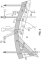
- FIGs. 1A-1D illustrate simplified, schematic views of an oilfield 100 having a subterranean formation 102 containing reservoir 104 therein in accordance with implementations of various technologies and techniques described herein.
- Figure 1A illustrates a survey operation being performed by a survey tool, such as seismic truck 106a, to measure properties of subterranean formations 102.
- the survey operation is a seismic survey operation for producing sound vibrations.
- one such sound vibration e.g., sound vibration 112 generated by source 110, reflects off horizons 114 in earth formation 116.
- a set of sound vibrations is received by sensors, including but not limited to geophone-receivers 118, situated on a surface of earth.
- Data received 120 may be provided as input data to a computer 122a of seismic truck 106a, and responsive to data received 120, computer 122a may generate seismic data output 124. Seismic data output 124 may be stored, transmitted or further processed as desired, for example, by data reduction.
- Fig. 1B illustrates a drilling operation being performed by drilling tools 106b suspended by a rig 128 and advanced into subterranean formations 102 to form a wellbore 136.
- a mud pit 130 may be used to draw drilling mud into drilling tools 106b via a flow line 132 for circulating the drilling mud down through drilling tools 106b, then up wellbore 136 and back to the surface. Typically, the drilling mud is filtered and returned to the mud pit.
- a circulating system may be used for storing, controlling, or filtering the flowing drilling mud.
- Drilling tools 106b may be advanced into subterranean formations 102 to reach reservoir 104. Each well may target one or more reservoirs. Drilling tools 106b are adapted for measuring downhole properties using logging while drilling tools. The logging while drilling tools also may be adapted for taking a core sample 133 as shown.
- Computer facilities may be positioned at various locations about oilfield 100 (e.g., surface unit 134) and/or at remote locations.
- a surface unit 134 may be used to communicate with drilling tools 106b and/or offsite operations, as well as with other surface or downhole sensors.
- Surface unit 134 may be capable of communicating with drilling tools 106b to send commands to drilling tools 106b, and to receive data therefrom.
- Surface unit 134 may also collect data generated during the drilling operation and produce a data output 135, which then may be stored or transmitted.
- Sensors (S), such as gauges, may be positioned about oilfield 100 to collect data relating to various oilfield operations as described previously. As shown, sensor (S) is positioned in one or more locations in drilling tools 106b and/or at rig 128 to measure drilling parameters including, but not limited to weight on bit, torque on bit, pressures, temperatures, flow rates, compositions, rotary speed, and/or other parameters of the oilfield operation. Sensors (S) may also be positioned in one or more locations in a circulating system.
- Drilling tools 106b may include a bottom hole assembly (BHA) (not shown), generally referenced, near a drill bit (e.g., within several drill collar lengths from the drill bit).
- BHA bottom hole assembly
- the bottom hole assembly includes capabilities for measuring, processing, and storing information, as well as communicating with surface unit 134.
- the bottom hole assembly further may include drill collars for performing various other measurement functions.
- the bottom hole assembly may include a communication subassembly that communicates with surface unit 134.
- the communication subassembly may be adapted to send signals to and receive signals from the surface using a communications channel including, but not limited to mud pulse telemetry, electro-magnetic telemetry, or wired drill pipe communications.
- the communication subassembly may include, for example, a transmitter that generates a signal, such as an acoustic or electromagnetic signal, which is representative of measured drilling parameters. It will be appreciated by one of skill in the art that a variety of telemetry systems may be employed, including, but not limited to wired drill pipe, electromagnetic or other known telemetry systems.
- a wellbore is drilled according to a drilling plan that is established prior to drilling.
- the drilling plan typically sets forth equipment, pressures, trajectories and/or other parameters that define a drilling process for the wellsite.
- a drilling operation may then be performed according to the drilling plan.
- the drilling operation may need to deviate from the drilling plan.
- subsurface conditions may change.
- an earth model may be adjusted.
- Data gathered by sensors (S) may be collected by surface unit 134 and/or other data collection sources for analysis or other processing.
- the data collected by sensors (S) may be used alone or in combination with other data.
- the data may be collected in one or more databases and/or transmitted on or offsite.
- the data may be historical data, real-time data, or combinations thereof.
- the real-time data may be used in real time, or stored for later use.
- the data also may be combined with historical data or other inputs for further analysis.
- the data may be stored in separate databases, or combined into a single database.
- Surface unit 134 may include transceiver 137 to allow communications between surface unit 134 and various portions of oilfield 100 or other locations. Surface unit 134 also may be provided with or functionally connected to one or more controllers (not shown) for actuating mechanisms at oilfield 100. Surface unit 134 then may send command signals to oilfield 100 in response to data received. Surface unit 134 may receive commands via transceiver 137 or may itself execute commands to the controller. A processor may be provided to analyze the data (locally or remotely), make decisions and/or actuate the controller. In this manner, oilfield 100 may be selectively adjusted based on the data collected. This technique may be used to optimize (or improve) portions of the oilfield operation, such as controlling drilling, weight on bit, pump rates, or other parameters. Adjustments may be made automatically based on computer protocol, and/or manually by an operator. In some cases, well plans may be adjusted to select optimum (or improved) operating conditions, or to avoid problems.
- Fig. 1C illustrates a wireline operation being performed by wireline tool 106c suspended by rig 128 and into wellbore 136 of Fig. 1C .
- Wireline tool 106c may be adapted for deployment into wellbore 136 for generating well logs, performing downhole tests and/or collecting samples.
- Wireline tool 106c may be used to provide another method and apparatus for performing a seismic survey operation.
- Wireline tool 106c may, for example, have an explosive, radioactive, electrical, or acoustic energy source 144 that sends and/or receives electrical signals to surrounding subterranean formations 102 and fluids therein.
- Wireline tool 106c may be operatively connected to, for example, geophones 118 or other sensing devices and computer 122a of a seismic truck 106a of Fig. 1A .
- Wireline tool 106c may also provide data to surface unit 134.
- Surface unit 134 may collect data generated during the wireline operation and may produce data output 135 that may be stored or transmitted.
- Wireline tool 106c may be positioned at various depths in wellbore 136 to provide a survey or other information relating to subterranean formations 102.
- Sensors such as gauges, may be positioned about oilfield 100 to collect data relating to various oilfield operations as described previously. As shown, sensor S is positioned in wireline tool 106c to measure downhole parameters which relate to, for example porosity, permeability, fluid composition and/or other parameters of the oilfield operation.
- Fig. 1D illustrates a production operation being performed by production tool 106d deployed from a production unit or Christmas tree 129 and into completed wellbore 136 for drawing fluid from the downhole reservoirs into surface facilities 142.
- the fluid may flow from reservoir 104 through perforations in a casing (not shown) and into production tool 106d in wellbore 136 and to surface facilities 142 via a gathering network 146.
- Sensors such as gauges, may be positioned about oilfield 100 to collect data relating to various oilfield operations as described previously. As shown, sensor (S) may be positioned in production tool 106d or associated equipment, such as Christmas tree 129, gathering network 146, surface facility 142, and/or the production facility, to measure fluid parameters, such as fluid composition, flow rates, pressures, temperatures, and/or other parameters of the production operation.
- Production may also include injection wells for added recovery.
- One or more gathering facilities may be operatively connected to one or more wellsites for selectively collecting downhole fluids from the wellsite(s).
- Figs. 1B-1D illustrate tools used to measure properties of an oilfield
- the tools may be used in connection with non-oilfield operations, such as gas fields, mines, aquifers, storage or other subterranean facilities.
- non-oilfield operations such as gas fields, mines, aquifers, storage or other subterranean facilities.
- various measurement tools capable of sensing parameters, such as seismic two-way travel time, density, resistivity, production rate, etc., of the subterranean formations and/or their geological formations may be used.
- Various sensors (S) may be located at various positions along the wellbore and/or the monitoring tools to collect and/or monitor the desired data. Other sources of data may also be provided from offsite locations.
- Figs. 1A-1D are intended to provide a brief description of an example of a field usable with oilfield application frameworks.
- Part of, or the entirety, of oilfield 100 may be on land, water and/or sea.
- oilfield applications may be utilized with any combination of one or more oilfields, one or more processing facilities and one or more wellsites.
- Fig. 2 illustrates a schematic view, partially in cross section of oilfield 200 having data acquisition tools 202a, 202b, 202c and 202d positioned at various locations along oilfield 200 for collecting data of subterranean formation 204 in accordance with implementations of various technologies and techniques described herein.
- Data acquisition tools 202a-202d may be the same as data acquisition tools 106a-106d of Figs. 1A-1D , respectively, or others not depicted.
- data acquisition tools 202a-202d may generate data plots or measurements 208a-208d, respectively. These data plots are depicted along oilfield 200 to demonstrate data generated by various operations.
- Data plots 208a-208c are examples of static data plots that may be generated by data acquisition tools 202a-202c, respectively; however, it should be understood that data plots 208a-208c may be updated in real time. These measurements may be analyzed to better define properties of the formation(s) and/or determine an accuracy of the measurements and/or for checking for errors. The plots of each of the respective measurements may be aligned and scaled for comparison and verification of the properties.
- Static data plot 208a is a seismic two-way response over a period of time.
- Static plot 208b is core sample data measured from a core sample of formation 204.
- the core sample may be used to provide data, such as a graph of density, porosity, permeability, or some other physical property of the core sample over a length of the core. Tests for density and viscosity may be performed on fluids in the core at varying pressures and temperatures.
- Static data plot 208.c is a logging trace that typically provides a resistivity or other measurement of the formation at various depths.
- a production decline curve or graph 208d is a dynamic data plot of fluid flow rate over time.
- the production decline curve typically provides a production rate as a function of time.
- measurements may be taken of fluid properties, such as flow rates, pressures, composition, etc.
- Other data may be collected, such as historical data, user inputs, economic information, and/or other measurement data and other parameters of interest.
- static and dynamic measurements may be analyzed and used to generate models of the subterranean formation to determine characteristics thereof. Similar measurements may also be used to measure changes in formation aspects over time.
- a subterranean structure may have multiple geological formations 206a-206d. As shown, this structure may have several formations or layers, including a first shale layer 206a, a carbonate layer 206b, a second shale layer 206c and a sand layer 206d. A fault 207 may extend through first shale layer 206a and carbonate layer 206b.
- the static data acquisition tools may be adapted to take measurements and detect characteristics of the formations.
- oilfield 200 may contain a variety of geological structures and/or formations, sometimes having extreme complexity. In some locations, typically below a water line, fluid may occupy pore spaces of the formations.
- Each of the measurement devices may be used to measure properties of the formations and/or their geological features. While each acquisition tool is shown as being in specific locations in oilfield 200, it will be appreciated that one or more types of measurement may be taken at one or more locations across one or more oilfields or other locations for comparison and/or analysis.
- the data collected from various sources may be processed and/or evaluated.
- seismic data displayed in static data plot 208a from data acquisition tool 202a may be used by a geophysicist to determine characteristics of the subterranean formations and features.
- the core data shown in static plot 208b and/or log data from a well log 208c are typically used by a geologist to determine various characteristics of a subterranean formation.
- the production data from graph 208d is typically used by a reservoir engineer to determine fluid flow reservoir characteristics.
- the data analyzed by the geologist, geophysicist and the reservoir engineer may be analyzed using modeling techniques.
- Fig. 3A illustrates an oilfield 300 for performing production operations in accordance with implementations of various technologies and techniques described herein.
- oilfield 300 has multiple wellsites 302 operatively connected to a central processing facility 354.
- a configuration of oilfield 300 is not intended to limit a scope of an oilfield application system. Part, or all, of an oilfield may be on land and/or sea.
- a single oilfield with a single processing facility and multiple wellsites is depicted in Fig. 3A , any combination of one or more oilfields, one or more processing facilities and one or more wellsites may be present.
- Each wellsite 302 has equipment that forms wellbore 336 into the earth.
- Wellbores 336 extend through subterranean formations 306 including reservoirs 304.
- Reservoirs 304 contain fluids, such as hydrocarbons.
- Wellsites 302 may draw fluid from reservoirs 304 and may pass the fluid to processing facilities via surface networks 344.
- Surface networks 344 may have tubing and control mechanisms for controlling a flow of fluids from wellsites 302 to processing facility 354.
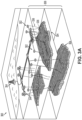
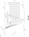
- Fig. 3B illustrates a side view of a marine-based survey 360 of a subterranean subsurface 362 in accordance with one or more implementations of various techniques described herein.
- Subsurface 362 includes seafloor surface 364.
- Seismic sources 366 may include marine sources such as vibroseis, airguns, or other marine sources, which may propagate seismic waves 368 (e.g., energy signals) into the earth over an extended period of time or at a nearly instantaneous energy provided by impulsive sources.
- Seismic waves 368 may be propagated by marine sources as a frequency sweep signal.
- marine sources of the vibroseis type may initially emit a seismic wave at a low frequency (e.g., 5 Hz) and may increase the seismic wave to a high frequency (e.g., 80-90 Hz) over time.
- Component(s) of seismic waves 368 may be reflected and converted by seafloor surface 364 (i.e., reflector), and seismic wave reflections 370 may be received by multiple seismic receivers 372.
- Seismic receivers 372 may be disposed on multiple streamers (i.e., a streamer array 374). Seismic receivers 372 may generate electrical signals representative of received seismic wave reflections 370. The electrical signals may be embedded with information regarding subsurface 362 captured as a record of seismic data.
- each streamer may include streamer steering devices such as a bird, a deflector, a tail buoy and the like, which are not illustrated in this application.
- the streamer steering devices may be used to control the position of the streamers in accordance with the techniques described herein.
- seismic wave reflections 370 may travel upward and reach a water/air interface at a water surface 376, a portion of reflections 370 may reflect downward again (i.e., sea-surface ghost waves 378) and be received by multiple seismic receivers 372. Sea-surface ghost waves 378 may be referred to as surface multiples. A point on the water surface 376 at which the wave is reflected downward is generally referred to as a downward reflection point.
- the electrical signals may be transmitted to a vessel 380 via transmission cables, wireless communication or the like. Vessel 380 then may transmit the electrical signals to a data processing center. Alternatively, vessel 380 may include an onboard computer capable of processing the electrical signals (i.e., seismic data).
- seismic data i.e., seismic data
- surveys may be of formations deep beneath the surface. The formations may typically include multiple reflectors, some of which may include dipping events, and may generate multiple reflections (including wave conversion) for receipt by seismic receivers 372.
- the seismic data may be processed to generate a seismic image of the subsurface 362.
- Marine seismic acquisition systems tow each streamer in streamer array 374 at a same depth (e.g., 5-10m).
- marine based survey 360 may tow each streamer in streamer array 374 at different depths such that seismic data may be acquired and processed in a manner that avoids the effects of destructive interference due to sea-surface ghost waves.
- marine-based survey 360 of Fig. 3B illustrates eight streamers towed by vessel 380 at eight different depths. The depth of each streamer may be controlled and maintained using the birds disposed on each streamer.
- a method uses an unsupervised deep learning technique for ground roll attenuation.
- a two-dimensional (2D) convolutional neural network (CNN) for separating ground rolls and reflections may be implemented.
- inputs and labels of the CNN are the same 2D shot gathers.
- the CNN includes, two, sub-networks: one for outputting low-frequency noise such as, for example, ground roll, and another for outputting reflection.
- the CNN may be configured to reduce a residual between a summation of the two sub-networks and the 2D shot gathers in time domain. Frequency constraint is used as a regularization of a loss function to guide the separating.
- a 2D convolutional encoder-decoder may be used to generate a binary mask for each shot gather.
- the method may include generating a binary mask for the individual shot gathers.
- a value is 1; otherwise, the value is 0.
- the mask may be used as an input to the CNN for low-frequency noise such as, for example, ground roll, and reflection separation, so that the overfitting of the random noise before first arrival could be avoided.
- Fig. 4 is a flowchart that illustrates an example process for generating the binary mask.
- the process of generating a mask may include three parts.
- a seismic image may be converted to a binary image, e.g., "binarize" the seismic image.
- A is an amplifier coefficient that may be set to, for example, 50 in some embodiments.
- an encoder-decoder neural network may be trained to generate a smooth image (act 406).
- inputs and labels may be the binary images generated above.
- input is a binary image and output is a smooth image.
- Fig. 5 illustrates the process of generating a mask including steps of binarizing seismic data, passing the binarized data through an encoder-decoder to generate a smooth image, and fitting the 0-1 boundary by using a sigmoid function.
- a fully convolutional neural network may be used for the encoder-decoder. While the input is speckled images, the encoder-decoder can filter a high frequency of the image and output a smooth image that contains main features of the input.
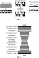
- An example architecture of the encoder-decoder is shown in Fig. 6 .
- the example architecture of Fig. 6 has six convolutional layers in total, in this embodiment.
- a max pooling method may be used after each convolutional layer in an encoder part and a nearest-neighbor interpolation method may be used before each convolutional layer in a decoder part.
- a relu activation may be used to add nonlinearity.
- a size of the training patches may be 128 ⁇ 128, but a size of input for the prediction can be different.
- Fig. 6 shows an architecture with six convolutional layers
- other embodiments may include additional or fewer convolutional layers.
- some embodiments may use an average pooling method after each convolutional layer in the encoder part and a different up sampling method in the decoder part.
- a CNN may include two 2D sub-networks: CNN A and CNN B. Training inputs and labels for both sub-networks may be the same seismic data with ground rolls.
- the binary mask may be applied to the seismic data before the seismic data passes through the two sub-networks. After the seismic data passes through the two sub-networks, one sub-network generates the low-frequency noise, including ground roll, and another sub-network generates reflection, with a summation of outputs of the two sub-networks and noise eliminated by the binary mask equaling original seismic data.
- the seismic data may have large oscillations, which makes a correlation between gradients of images unreliable or failure-prone as a criterion for image separation.
- Frequency constraint may thus be used to guide the separation, considering a low frequency characteristic of ground roll signals.
- a set of 2D sections are provided as input to the CNN A and the CNN B.
- the set of sections typically are divided into training patches, wherein the N is a number of 2D sections included in a training patch.
- F( ⁇ ) is the 2D Fourier transform function
- W is a predefined number representing the window size in the frequency domain
- WP is the number of pixels for computing the mean value of the summation.
- Minimizing L low may minimize the low frequency component in X.
- the regularization coefficient ⁇ 1 may be small.
- the parameters W, ⁇ 1 and ⁇ 2 may be trade-off parameters.
- W may be set to 60 (corresponding to 15 Hz)
- ⁇ 1 may be set to 0.0009
- ⁇ 2 may be set to 0.0025.
- CNN A/B An example architecture of CNN A/B is shown in Fig. 8 .
- CNN A which outputs high frequency signals
- a number of layers in each stack convolution may be 3; in CNN B, which outputs low frequency signals, 2-layer stack convolution may be used.
- a skip connection from an output of the first stack convolution to an input of the last stack convolution may be added.
- the skip connection brings faster convergence during training and better performance regarding preservation of data precision in test cases.
- max pooling and a nearest-neighbor interpolation method may be used for down sampling and up sampling, respectively, and a rectified linear activation function (relu) may be used after each convolutional layer except an output layer.
- average pooling may be used for down sampling and a different method may be used for up sampling.
- training may be achieved by using an Adam optimizer with an exponential decay learning rate.
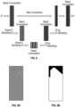
- 3D land shot gathers contaminated with ground rolls were used as a training set.
- a size of training patches was 2048 ⁇ 80, with a record time ranging from 0 to 4.096 seconds.
- masks were generated in a first stage.
- Fig. 9A shows one of the training patches and Fig. 9B shows its corresponding mask.
- Fig. 10A The input is shown in Fig. 10A .
- the output Y of CNN B is shown in Fig. 10B , which represents estimated ground roll signals. Subtracting the estimated ground roll signals in Fig. 10B from the input shown in Fig. 10A yields a result after ground roll attenuation as shown in Fig. 10C. Fig. 10C shows that most of the ground rolls have been extracted after passing through the network.
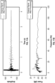
- Figs. 11A and 11B the time and frequency domain of curve 151 (see Figs. 10A and 10C ) before and after attenuation are shown in Figs. 11A and 11B , respectively.
- Fig. 11B low frequency components have been suppressed by nearly two orders.
- a time series of Fig. 11A shows that low component harmonics are largely removed.
- the present disclosure includes an unsupervised deep learning approach to ground roll attenuation.
- the training does not call for extra effort to generate labels, which gives this method flexibility in field data ground roll attenuation.
- the nonlinear neural network helps to preserve the reflections' low frequency components while separating ground roll with high computation efficiency. This method has been validated with various field data test.
- the described functions can be implemented in hardware, software, firmware, or any combination thereof.
- techniques described herein can be implemented with modules (e.g., procedures, functions, subprograms, programs, routines, subroutines, modules, software packages, classes, and so on) that perform the functions described herein.
- a module can be coupled to another module or a hardware circuit by passing and/or receiving information, data, arguments, parameters, or memory contents.
- Information, arguments, parameters, data, or the like can be passed, forwarded, or transmitted using any suitable means including memory sharing, message passing, token passing, network transmission, and the like.
- the software code can be stored in memory units and executed by processors.
- the memory unit can be implemented within the processor or external to the processor, in which case it can be communicatively coupled to the processor via various means as is known in the art.
- any of the methods of the present disclosure may be executed by a computing system.
- Fig. 12 illustrates an example of such a computing system 1200, in accordance with some embodiments.
- the computing system 1200 may include a computer or computer system 1201A, which may be an individual computer system 1201A or an arrangement of distributed computer systems.
- the computer system 1201A may include one or more analysis module(s) 1202 configured to perform various tasks according to some embodiments, such as one or more methods disclosed herein. To perform these various tasks, analysis module 1202 executes independently, or in coordination with, one or more processors 1204, which is (or are) connected to one or more storage media 1206.
- Processor(s) 1204 is (or are) also connected to a network interface 1207 to allow computer system 1201A to communicate over a data network 1209 with one or more additional computer systems and/or computing systems, such as 1201B, 1201C, and/or 1201D (note that computer systems 1201B, 1201C and/or 1201D may or may not share the same architecture as computer system 1201A, and may be located in different physical locations, e.g., computer systems 1201A and 1201B may be located in a processing facility, while in communication with one or more computer systems such as 1201C and/or 1201D that may be located in one or more data centers, and/or located in various countries that may be on different continents).
- 1201B, 1201C and/or 1201D may or may not share the same architecture as computer system 1201A, and may be located in different physical locations, e.g., computer systems 1201A and 1201B may be located in a processing facility, while in communication with one or more computer systems such as 1201
- a processor can include a microprocessor, microcontroller, processor module or subsystem, programmable integrated circuit, programmable gate array, or another control or computing device.
- Storage media 1206 can be implemented as one or more computer-readable or machine-readable storage media. Note that while in the example embodiment of Fig. 12 storage media 1206 is depicted as within computer system 1201A, in some embodiments, storage media 1206 may be distributed within and/or across multiple internal and/or external enclosures of computing system 1201A and/or additional computing systems.
- Storage media 1206 may include one or more different forms of memory including semiconductor memory devices such as dynamic or static random access memories (DRAMs or SRAMs), erasable and programmable read-only memories (EPROMs), electrically erasable and programmable read-only memories (EEPROMs) and flash memories, magnetic disks such as fixed, floppy and removable disks, other magnetic media including tape, optical media such as compact disks (CDs) or digital video disks (DVDs), BLURAY disks, or other types of optical storage, or other types of storage devices.
- semiconductor memory devices such as dynamic or static random access memories (DRAMs or SRAMs), erasable and programmable read-only memories (EPROMs), electrically erasable and programmable read-only memories (EEPROMs) and flash memories
- magnetic disks such as fixed, floppy and removable disks, other magnetic media including tape
- optical media such as compact disks (CDs) or digital video disks (DVDs)
- DVDs digital video disks
- Such computer-readable or machine-readable storage medium or media is (are) considered to be part of an article (or article of manufacture).
- An article or article of manufacture can refer to any manufactured single component or multiple components.
- the storage medium or media can be located either in the machine running the machine-readable instructions, or located at a remote site from which machine-readable instructions can be downloaded over a network for execution.
- computing system 1200 may contain one or more attenuation module(s) 1208.
- computer system 1201A may include an attenuation module 1208.
- a single attenuation module may be used to perform some or all aspects of one or more embodiments of the methods.
- multiple attenuation modules may be used to perform some or all aspects of methods.
- computing system 1200 is only one example of a computing system, and that computing system 1100 may have more or fewer components than shown, may combine additional components not depicted in the example embodiment of Fig. 12 , and/or computing system 1200 may have a different configuration or arrangement of the components depicted in Fig. 12 .
- the various components shown in Fig. 12 may be implemented in hardware, software, or a combination of both hardware and software, including one or more signal processing and/or application specific integrated circuits.
- steps in the processing methods described herein may be implemented by running one or more functional modules in information processing apparatus such as general purpose processors or application specific chips, such as ASICs, FPGAs, PLDs, or other appropriate devices.
- information processing apparatus such as general purpose processors or application specific chips, such as ASICs, FPGAs, PLDs, or other appropriate devices.
- Geologic interpretations, models and/or other interpretation aids may be refined in an iterative fashion; this concept is applicable to embodiments of the present methods discussed herein.
- This can include use of feedback loops executed on an algorithmic basis, such as at a computing device (e.g., computing system 1200, Fig. 12 ), and/or through manual control by a user who may make determinations regarding whether a given step, action, template, model, or set of curves has become sufficiently accurate for the evaluation of the subsurface three-dimensional geologic formation under consideration.
Landscapes
- Engineering & Computer Science (AREA)
- Physics & Mathematics (AREA)
- Theoretical Computer Science (AREA)
- Life Sciences & Earth Sciences (AREA)
- General Physics & Mathematics (AREA)
- Remote Sensing (AREA)
- Software Systems (AREA)
- General Engineering & Computer Science (AREA)
- Data Mining & Analysis (AREA)
- Evolutionary Computation (AREA)
- Mathematical Physics (AREA)
- Artificial Intelligence (AREA)
- Computing Systems (AREA)
- Computational Linguistics (AREA)
- Molecular Biology (AREA)
- General Health & Medical Sciences (AREA)
- Biophysics (AREA)
- Biomedical Technology (AREA)
- Health & Medical Sciences (AREA)
- Environmental & Geological Engineering (AREA)
- Acoustics & Sound (AREA)
- Geology (AREA)
- General Life Sciences & Earth Sciences (AREA)
- Geophysics (AREA)
- Computer Vision & Pattern Recognition (AREA)
- Medical Informatics (AREA)
- Geophysics And Detection Of Objects (AREA)
- Image Analysis (AREA)
Claims (9)
- Computerimplementiertes (1200) Verfahren zum Dämpfen von Rauschen in seismischen Daten, umfassend: Empfangen eines seismischen Bildes;Erzeugen eines ersten Bildes unter Verwendung eines ersten neuronalen Netzwerks, das konfiguriert ist, um niederfrequentes Rauschen in dem seismischen Bild zu identifizieren;Erzeugen eines zweiten Bildes unter Verwendung eines zweiten neuronalen Netzwerks, das konfiguriert ist, um Reflexionen (370) in dem seismischen Bild zu identifizieren und das niederfrequente Rauschen zu dämpfen;wobei das Verfahren dadurch gekennzeichnet ist, dass es ferner umfasst:Erzeugen eines kombinierten Bildes durch Kombinieren des ersten Bildes und des zweiten Bildes;Anpassen des ersten neuronalen Netzwerks und des zweiten neuronalen Netzwerks, um eine Differenz zwischen dem kombinierten Bild und dem seismischen Bild zu reduzieren, wobei eine Frequenzbeschränkung verwendet wird, um die Trennung des seismischen Bildes in das erste Bild und das zweite Bild zu steuern; undAusgeben eines Ergebnisses des Verfahrens zum Durchführen eines Ölfeldvorgangs.
- Verfahren nach Anspruch 1, ferner umfassend:
vor dem Erzeugen des ersten Bildes und des zweiten Bildes, Erzeugen einer binären Maske durch das Computersystem, wobei die binäre Maske in einem Bereich vor der ersten Ankunft einen Wert von 1 und ansonsten einen Wert von 0 aufweist, wobei das Erzeugen der binären Maske umfasst:Binarisieren (404) einer Vielzahl von seismischen Bildern;Trainieren (406) eines neuronalen Kodierer-Dekodierer-Netzwerks, um aus den binarisierten seismischen Bildern ein geglättetes Bild zu erzeugen; undAnpassen (408) einer 0-1-Grenze in vertikaler Richtung mit einer Sigmoidfunktion. - Verfahren nach Anspruch 2, wobei:der Gesamtdatenverlust (Ltotal) eine Summe aus dem Datenverlust (Ldata), einem Produkt eines ersten Koeffizienten (λ1) mit einem ersten Regularisierungsterm (Llow), der eine erste Frequenzbeschränkung auferlegt, und einem Produkt eines zweiten Koeffizienten (λ2) mit einem zweiten Regularisierungsterm (Lhigh), der eine zweite Frequenzbeschränkung auferlegt, ist, wobei die Gesamtdatenverlustfunktion (Ltotal) wie folgt geschrieben wird:
 der Datenverlust (L data ) gleich einem Quotienten ist, der berechnet wird, indem ein Produkt einer quadrierten Frobenius-Norm (∥...∥F 2 ) der ursprünglich empfangenen seismischen Daten (Z*), subtrahiert von einer elementweisen Multiplikation (⊗) der binären Maske (M) mit einer Summierung (Z) von Ausgängen des ersten neuronalen Netzwerks und des zweiten neuronalen Netzwerks, durch eine Anzahl von 2D-Datenabschnitten pro Patch (N) dividiert wird, wobei der Datenverlust (L data ) definiert ist als:
 der erste Regularisierungsterm (Llow) gleich einem Quotienten einer ersten Summierung entlang eines ersten diskreten Frequenzbereichs in einer vertikalen Richtung von null durch eine Fenstergröße (W) in dem ersten diskreten Frequenzbereich (
 der zweite Regularisierungsterm (Lhigh) gleich einem Quotienten einer zweiten Summierung entlang des ersten diskreten Frequenzbereichs in einer vertikalen Richtung von eins plus der Fenstergröße (W) in dem ersten diskreten Frequenzbereich durch Q (
 der erste diskrete Frequenzbereich 1, ..., Q ist, undein zweiter diskreter Frequenzbereich in einer horizontalen Richtung 1, ..., P ist.
 - Verfahren nach Anspruch 2, ferner umfassend:
Anwenden der binären Maske auf das empfangene seismische Bild, um das Rauschen vor dem Bereich der ersten Ankunft in dem empfangenen seismischen Bild zu maskieren, bevor das erste Bild und das zweite Bild aus dem seismischen Bild erzeugt werden. - Verfahren nach Anspruch 1, wobei eine Architektur sowohl des ersten neuronalen Netzwerks als auch des zweiten neuronalen Netzwerks umfasst:eine erste Vielzahl von Stapeln erster Faltungsschichten, die durch jeweiliges Downsampling getrennt sind;eine zweite Vielzahl von Stapeln zweiter Faltungsschichten, die durch jeweiliges Upsampling getrennt sind; undeine Relu-Aktivierungsfunktion nach jeder Faltungsschicht der ersten und der zweiten Faltungsschichten mit Ausnahme einer Ausgangsschicht.
- Verfahren nach Anspruch 5, wobei die Architektur sowohl des ersten neuronalen Netzwerks als auch des zweiten neuronalen Netzwerks ferner umfasst:
eine Skip-Verbindung von einem Ausgang eines ersten Stapels der ersten Vielzahl von Stapeln zu einem Eingang eines letzten Stapels der zweiten Vielzahl von Stapeln. - Verfahren nach Anspruch 1, ferner umfassend:
Normalisieren seismischer Daten aus dem seismischen Bild durch das Computersystem (1200), bevor das seismische Bild dem ersten neuronalen Netz und dem zweiten neuronalen Netz bereitgestellt wird. - Mindestens ein nicht flüchtiges computerlesbares Medium (1206), das Anweisungen speichert, die, wenn sie von mindestens einem Prozessor (1204) eines Computersystems (1200) ausgeführt werden, das Computersystem veranlassen, Vorgänge auszuführen, wobei die Vorgänge die Schritte des Verfahrens nach einem der vorstehenden Ansprüche umfassen.
- Computersystem (1200) zum Dämpfen von niederfrequentem Bodenrollen, umfassend:einen oder mehrere Prozessoren (1204); undein Speichersystem, umfassend ein oder mehrere nicht flüchtige computerlesbare Medien (1206), die Anweisungen speichern, die, wenn sie durch mindestens einen des einen oder der mehreren Prozessoren ausgeführt werden, das Computersystem veranlassen, Vorgänge durchzuführen, die Vorgänge umfassend die Schritte des Verfahrens nach einem der Ansprüche 1 bis 7.
Applications Claiming Priority (2)
| Application Number | Priority Date | Filing Date | Title |
|---|---|---|---|
| US202062993817P | 2020-03-24 | 2020-03-24 | |
| PCT/US2021/023415 WO2021194933A1 (en) | 2020-03-24 | 2021-03-22 | Ground roll attenuation using unsupervised deep learning |
Publications (3)
| Publication Number | Publication Date |
|---|---|
| EP4128091A1 EP4128091A1 (de) | 2023-02-08 |
| EP4128091A4 EP4128091A4 (de) | 2024-03-20 |
| EP4128091B1 true EP4128091B1 (de) | 2025-05-07 |
Family
ID=77892267
Family Applications (1)
| Application Number | Title | Priority Date | Filing Date |
|---|---|---|---|
| EP21776200.4A Active EP4128091B1 (de) | 2020-03-24 | 2021-03-22 | Bodenwellendämpfung unter verwendung von unüberwachtem deep learning |
Country Status (4)
| Country | Link |
|---|---|
| US (1) | US12313800B2 (de) |
| EP (1) | EP4128091B1 (de) |
| CA (1) | CA3176814A1 (de) |
| WO (1) | WO2021194933A1 (de) |
Families Citing this family (7)
| Publication number | Priority date | Publication date | Assignee | Title |
|---|---|---|---|---|
| US20220253713A1 (en) * | 2021-02-05 | 2022-08-11 | Google Llc | Training neural networks using layer-wise losses |
| US12154252B2 (en) * | 2021-09-30 | 2024-11-26 | Saudi Arabian Oil Company | Method for denoising wellbore image logs utilizing neural networks |
| CN114114421B (zh) * | 2021-11-05 | 2023-09-29 | 中国石油大学(华东) | 基于深度学习的导向自学习地震数据去噪方法及装置 |
| CN115272156B (zh) * | 2022-09-01 | 2023-06-30 | 中国海洋大学 | 基于循环生成对抗网络的油气藏高分辨率井筒成像表征法 |
| US20250231311A1 (en) * | 2024-01-16 | 2025-07-17 | Saudi Arabian Oil Company | Generating Seismic Images of a Subsurface Formation |
| CN118458966B (zh) * | 2024-05-30 | 2025-10-24 | 上海东方泵业集团南通有限公司 | 一体化污水处理设备的鼓风搅拌淤泥智能控制系统 |
| CN120577873B (zh) * | 2025-08-01 | 2025-10-03 | 中国石油大学(华东) | 一种时频域混合损失约束卷积网络的地震数据去噪方法 |
Family Cites Families (14)
| Publication number | Priority date | Publication date | Assignee | Title |
|---|---|---|---|---|
| WO2016185223A1 (en) * | 2015-05-20 | 2016-11-24 | Optasense, Inc. | Interferometric microseismic imaging methods and apparatus |
| US10839226B2 (en) * | 2016-11-10 | 2020-11-17 | International Business Machines Corporation | Neural network training |
| JP6581068B2 (ja) * | 2016-11-11 | 2019-09-25 | 株式会社東芝 | 画像処理装置、画像処理方法、プログラム、運転制御システム、および、車両 |
| US10916001B2 (en) * | 2016-11-28 | 2021-02-09 | Adobe Inc. | Facilitating sketch to painting transformations |
| US11169293B2 (en) * | 2016-12-13 | 2021-11-09 | Cgg Services Sas | Device and method for model-based deblending |
| US10789694B1 (en) * | 2017-09-11 | 2020-09-29 | Apple Inc. | Real-time adjustment of temporal consistency constraints for video style |
| DE102018128592A1 (de) * | 2017-11-15 | 2019-05-16 | Nvidia Corporation | Erzeugen eines Bilds unter Verwendung einer Map, die verschiedene Klassen von Pixeln repräsentiert |
| US11105942B2 (en) * | 2018-03-27 | 2021-08-31 | Schlumberger Technology Corporation | Generative adversarial network seismic data processor |
| CN112367915B (zh) * | 2018-06-15 | 2025-01-07 | 佳能株式会社 | 医学图像处理装置、医学图像处理方法和计算机可读介质 |
| KR102240839B1 (ko) * | 2018-09-04 | 2021-04-16 | 씨드로닉스(주) | 이미지 세그멘테이션을 이용한 자율 운항 방법 |
| WO2020080765A1 (en) * | 2018-10-19 | 2020-04-23 | Samsung Electronics Co., Ltd. | Apparatuses and methods for performing artificial intelligence encoding and artificial intelligence decoding on image |
| WO2021044256A1 (en) * | 2019-09-03 | 2021-03-11 | Chevron U.S.A. Inc. | System and method for seismic imaging of subsurface volumes including complex geology |
| US11080889B2 (en) * | 2019-09-24 | 2021-08-03 | Shanghai United Imaging Intelligence Co., Ltd. | Methods and systems for providing guidance for adjusting an object based on similarity |
| JP7231762B2 (ja) * | 2019-11-29 | 2023-03-01 | オリンパス株式会社 | 画像処理方法、学習装置、画像処理装置及びプログラム |
-
2021
- 2021-03-22 EP EP21776200.4A patent/EP4128091B1/de active Active
- 2021-03-22 CA CA3176814A patent/CA3176814A1/en active Pending
- 2021-03-22 US US17/907,003 patent/US12313800B2/en active Active
- 2021-03-22 WO PCT/US2021/023415 patent/WO2021194933A1/en not_active Ceased
Also Published As
| Publication number | Publication date |
|---|---|
| CA3176814A1 (en) | 2021-09-30 |
| WO2021194933A1 (en) | 2021-09-30 |
| US12313800B2 (en) | 2025-05-27 |
| EP4128091A4 (de) | 2024-03-20 |
| US20230109902A1 (en) | 2023-04-13 |
| EP4128091A1 (de) | 2023-02-08 |
Similar Documents
| Publication | Publication Date | Title |
|---|---|---|
| EP4128091B1 (de) | Bodenwellendämpfung unter verwendung von unüberwachtem deep learning | |
| US12093346B2 (en) | Unsupervised well log reconstruction and outlier detection | |
| US20240061136A1 (en) | Source separation using multistage inversion with sparsity promoting priors | |
| US11988790B2 (en) | Residual signal detection for noise attenuation | |
| US20240418888A1 (en) | Forecasting co2 plume bodies in sequestration operations | |
| US12099156B2 (en) | Combining noise attenuation and wavefield reconstruction in seismic processing | |
| US11531131B2 (en) | Seismic interpretation using flow fields | |
| US12129757B2 (en) | Automatic well log correction | |
| US20240377546A1 (en) | Systems and methods for modeling a subsurface volume using time-lapse data | |
| US20250155598A1 (en) | Repeatability enforcement for measured data | |
| US20180059274A1 (en) | Post-critical reflection muting in seismic migration | |
| US12242006B2 (en) | Simultaneous shooting time-lapse seismic data deblending for CO2 monitoring and time lapse simultaneous shooting scheme recommender | |
| US12253642B2 (en) | Quantifying diversity in seismic datasets | |
| US20250078497A1 (en) | Detecting a scale type of well-log properties in raster images | |
| US20240362383A1 (en) | Time lapse data reconstruction and time lapse data acquisition survey design for co2 monitoring | |
| EP4471464A1 (de) | Automatisierung der parametrisierung einer mehrstufigen iterativen quellentrennung mit priorisierung mittels maschinellem lernen | |
| US20240054398A1 (en) | Machine learning training based on dual loss functions | |
| WO2024145017A1 (en) | Multi-stage iterative source separation with prior for time-lapse acquisition |
Legal Events
| Date | Code | Title | Description |
|---|---|---|---|
| STAA | Information on the status of an ep patent application or granted ep patent |
Free format text: STATUS: THE INTERNATIONAL PUBLICATION HAS BEEN MADE |
|
| PUAI | Public reference made under article 153(3) epc to a published international application that has entered the european phase |
Free format text: ORIGINAL CODE: 0009012 |
|
| STAA | Information on the status of an ep patent application or granted ep patent |
Free format text: STATUS: REQUEST FOR EXAMINATION WAS MADE |
|
| 17P | Request for examination filed |
Effective date: 20220923 |
|
| AK | Designated contracting states |
Kind code of ref document: A1 Designated state(s): AL AT BE BG CH CY CZ DE DK EE ES FI FR GB GR HR HU IE IS IT LI LT LU LV MC MK MT NL NO PL PT RO RS SE SI SK SM TR |
|
| DAV | Request for validation of the european patent (deleted) | ||
| DAX | Request for extension of the european patent (deleted) | ||
| A4 | Supplementary search report drawn up and despatched |
Effective date: 20240216 |
|
| RIC1 | Information provided on ipc code assigned before grant |
Ipc: G06Q 10/0633 20230101ALI20240212BHEP Ipc: G06N 3/08 20230101ALI20240212BHEP Ipc: G06N 3/048 20230101ALI20240212BHEP Ipc: G06N 3/045 20230101ALI20240212BHEP Ipc: G01V 1/36 20060101ALI20240212BHEP Ipc: E21B 44/00 20060101ALI20240212BHEP Ipc: G01V 1/00 20060101ALI20240212BHEP Ipc: G06Q 50/02 20120101ALI20240212BHEP Ipc: G06N 3/00 20230101ALI20240212BHEP Ipc: G06N 20/00 20190101AFI20240212BHEP |
|
| GRAP | Despatch of communication of intention to grant a patent |
Free format text: ORIGINAL CODE: EPIDOSNIGR1 |
|
| STAA | Information on the status of an ep patent application or granted ep patent |
Free format text: STATUS: GRANT OF PATENT IS INTENDED |
|
| INTG | Intention to grant announced |
Effective date: 20241211 |
|
| GRAS | Grant fee paid |
Free format text: ORIGINAL CODE: EPIDOSNIGR3 |
|
| GRAA | (expected) grant |
Free format text: ORIGINAL CODE: 0009210 |
|
| STAA | Information on the status of an ep patent application or granted ep patent |
Free format text: STATUS: THE PATENT HAS BEEN GRANTED |
|
| AK | Designated contracting states |
Kind code of ref document: B1 Designated state(s): AL AT BE BG CH CY CZ DE DK EE ES FI FR GB GR HR HU IE IS IT LI LT LU LV MC MK MT NL NO PL PT RO RS SE SI SK SM TR |
|
| REG | Reference to a national code |
Ref country code: GB Ref legal event code: FG4D |
|
| REG | Reference to a national code |
Ref country code: CH Ref legal event code: EP |
|
| REG | Reference to a national code |
Ref country code: DE Ref legal event code: R096 Ref document number: 602021030511 Country of ref document: DE |
|
| REG | Reference to a national code |
Ref country code: IE Ref legal event code: FG4D |
|
| REG | Reference to a national code |
Ref country code: NL Ref legal event code: FP |
|
| PG25 | Lapsed in a contracting state [announced via postgrant information from national office to epo] |
Ref country code: PT Free format text: LAPSE BECAUSE OF FAILURE TO SUBMIT A TRANSLATION OF THE DESCRIPTION OR TO PAY THE FEE WITHIN THE PRESCRIBED TIME-LIMIT Effective date: 20250908 Ref country code: FI Free format text: LAPSE BECAUSE OF FAILURE TO SUBMIT A TRANSLATION OF THE DESCRIPTION OR TO PAY THE FEE WITHIN THE PRESCRIBED TIME-LIMIT Effective date: 20250507 Ref country code: ES Free format text: LAPSE BECAUSE OF FAILURE TO SUBMIT A TRANSLATION OF THE DESCRIPTION OR TO PAY THE FEE WITHIN THE PRESCRIBED TIME-LIMIT Effective date: 20250507 |
|
| REG | Reference to a national code |
Ref country code: LT Ref legal event code: MG9D |
|
| PG25 | Lapsed in a contracting state [announced via postgrant information from national office to epo] |
Ref country code: GR Free format text: LAPSE BECAUSE OF FAILURE TO SUBMIT A TRANSLATION OF THE DESCRIPTION OR TO PAY THE FEE WITHIN THE PRESCRIBED TIME-LIMIT Effective date: 20250808 |
|
| PG25 | Lapsed in a contracting state [announced via postgrant information from national office to epo] |
Ref country code: PL Free format text: LAPSE BECAUSE OF FAILURE TO SUBMIT A TRANSLATION OF THE DESCRIPTION OR TO PAY THE FEE WITHIN THE PRESCRIBED TIME-LIMIT Effective date: 20250507 |
|
| REG | Reference to a national code |
Ref country code: AT Ref legal event code: MK05 Ref document number: 1793297 Country of ref document: AT Kind code of ref document: T Effective date: 20250507 |
|
| PG25 | Lapsed in a contracting state [announced via postgrant information from national office to epo] |
Ref country code: BG Free format text: LAPSE BECAUSE OF FAILURE TO SUBMIT A TRANSLATION OF THE DESCRIPTION OR TO PAY THE FEE WITHIN THE PRESCRIBED TIME-LIMIT Effective date: 20250507 |
|
| PG25 | Lapsed in a contracting state [announced via postgrant information from national office to epo] |
Ref country code: HR Free format text: LAPSE BECAUSE OF FAILURE TO SUBMIT A TRANSLATION OF THE DESCRIPTION OR TO PAY THE FEE WITHIN THE PRESCRIBED TIME-LIMIT Effective date: 20250507 |
|
| PG25 | Lapsed in a contracting state [announced via postgrant information from national office to epo] |
Ref country code: AT Free format text: LAPSE BECAUSE OF FAILURE TO SUBMIT A TRANSLATION OF THE DESCRIPTION OR TO PAY THE FEE WITHIN THE PRESCRIBED TIME-LIMIT Effective date: 20250507 |
|
| PG25 | Lapsed in a contracting state [announced via postgrant information from national office to epo] |
Ref country code: RS Free format text: LAPSE BECAUSE OF FAILURE TO SUBMIT A TRANSLATION OF THE DESCRIPTION OR TO PAY THE FEE WITHIN THE PRESCRIBED TIME-LIMIT Effective date: 20250807 |
|
| PG25 | Lapsed in a contracting state [announced via postgrant information from national office to epo] |
Ref country code: IS Free format text: LAPSE BECAUSE OF FAILURE TO SUBMIT A TRANSLATION OF THE DESCRIPTION OR TO PAY THE FEE WITHIN THE PRESCRIBED TIME-LIMIT Effective date: 20250907 |
|
| PG25 | Lapsed in a contracting state [announced via postgrant information from national office to epo] |
Ref country code: LV Free format text: LAPSE BECAUSE OF FAILURE TO SUBMIT A TRANSLATION OF THE DESCRIPTION OR TO PAY THE FEE WITHIN THE PRESCRIBED TIME-LIMIT Effective date: 20250507 |