EP4127761B1 - Drohnenstatusschätzung durch eine einzelbasisstation - Google Patents
Drohnenstatusschätzung durch eine einzelbasisstation Download PDFInfo
- Publication number
- EP4127761B1 EP4127761B1 EP20718789.9A EP20718789A EP4127761B1 EP 4127761 B1 EP4127761 B1 EP 4127761B1 EP 20718789 A EP20718789 A EP 20718789A EP 4127761 B1 EP4127761 B1 EP 4127761B1
- Authority
- EP
- European Patent Office
- Prior art keywords
- wireless device
- network node
- information
- wireless
- processing circuitry
- Prior art date
- Legal status (The legal status is an assumption and is not a legal conclusion. Google has not performed a legal analysis and makes no representation as to the accuracy of the status listed.)
- Active
Links
Images


Classifications
-
- G—PHYSICS
- G01—MEASURING; TESTING
- G01S—RADIO DIRECTION-FINDING; RADIO NAVIGATION; DETERMINING DISTANCE OR VELOCITY BY USE OF RADIO WAVES; LOCATING OR PRESENCE-DETECTING BY USE OF THE REFLECTION OR RERADIATION OF RADIO WAVES; ANALOGOUS ARRANGEMENTS USING OTHER WAVES
- G01S5/00—Position-fixing by co-ordinating two or more direction or position line determinations; Position-fixing by co-ordinating two or more distance determinations
- G01S5/01—Determining conditions which influence positioning, e.g. radio environment, state of motion or energy consumption
- G01S5/017—Detecting state or type of motion
-
- G—PHYSICS
- G01—MEASURING; TESTING
- G01S—RADIO DIRECTION-FINDING; RADIO NAVIGATION; DETERMINING DISTANCE OR VELOCITY BY USE OF RADIO WAVES; LOCATING OR PRESENCE-DETECTING BY USE OF THE REFLECTION OR RERADIATION OF RADIO WAVES; ANALOGOUS ARRANGEMENTS USING OTHER WAVES
- G01S5/00—Position-fixing by co-ordinating two or more direction or position line determinations; Position-fixing by co-ordinating two or more distance determinations
- G01S5/02—Position-fixing by co-ordinating two or more direction or position line determinations; Position-fixing by co-ordinating two or more distance determinations using radio waves
- G01S5/0257—Hybrid positioning
- G01S5/0258—Hybrid positioning by combining or switching between measurements derived from different systems
-
- G—PHYSICS
- G01—MEASURING; TESTING
- G01S—RADIO DIRECTION-FINDING; RADIO NAVIGATION; DETERMINING DISTANCE OR VELOCITY BY USE OF RADIO WAVES; LOCATING OR PRESENCE-DETECTING BY USE OF THE REFLECTION OR RERADIATION OF RADIO WAVES; ANALOGOUS ARRANGEMENTS USING OTHER WAVES
- G01S5/00—Position-fixing by co-ordinating two or more direction or position line determinations; Position-fixing by co-ordinating two or more distance determinations
- G01S5/02—Position-fixing by co-ordinating two or more direction or position line determinations; Position-fixing by co-ordinating two or more distance determinations using radio waves
- G01S5/0257—Hybrid positioning
- G01S5/0268—Hybrid positioning by deriving positions from different combinations of signals or of estimated positions in a single positioning system
- G01S5/02685—Hybrid positioning by deriving positions from different combinations of signals or of estimated positions in a single positioning system involving dead reckoning based on radio wave measurements
-
- G—PHYSICS
- G01—MEASURING; TESTING
- G01S—RADIO DIRECTION-FINDING; RADIO NAVIGATION; DETERMINING DISTANCE OR VELOCITY BY USE OF RADIO WAVES; LOCATING OR PRESENCE-DETECTING BY USE OF THE REFLECTION OR RERADIATION OF RADIO WAVES; ANALOGOUS ARRANGEMENTS USING OTHER WAVES
- G01S5/00—Position-fixing by co-ordinating two or more direction or position line determinations; Position-fixing by co-ordinating two or more distance determinations
- G01S5/02—Position-fixing by co-ordinating two or more direction or position line determinations; Position-fixing by co-ordinating two or more distance determinations using radio waves
- G01S5/0269—Inferred or constrained positioning, e.g. employing knowledge of the physical or electromagnetic environment, state of motion or other contextual information to infer or constrain a position
-
- G—PHYSICS
- G01—MEASURING; TESTING
- G01S—RADIO DIRECTION-FINDING; RADIO NAVIGATION; DETERMINING DISTANCE OR VELOCITY BY USE OF RADIO WAVES; LOCATING OR PRESENCE-DETECTING BY USE OF THE REFLECTION OR RERADIATION OF RADIO WAVES; ANALOGOUS ARRANGEMENTS USING OTHER WAVES
- G01S5/00—Position-fixing by co-ordinating two or more direction or position line determinations; Position-fixing by co-ordinating two or more distance determinations
- G01S5/02—Position-fixing by co-ordinating two or more direction or position line determinations; Position-fixing by co-ordinating two or more distance determinations using radio waves
- G01S5/0294—Trajectory determination or predictive filtering, e.g. target tracking or Kalman filtering
-
- G—PHYSICS
- G01—MEASURING; TESTING
- G01S—RADIO DIRECTION-FINDING; RADIO NAVIGATION; DETERMINING DISTANCE OR VELOCITY BY USE OF RADIO WAVES; LOCATING OR PRESENCE-DETECTING BY USE OF THE REFLECTION OR RERADIATION OF RADIO WAVES; ANALOGOUS ARRANGEMENTS USING OTHER WAVES
- G01S5/00—Position-fixing by co-ordinating two or more direction or position line determinations; Position-fixing by co-ordinating two or more distance determinations
- G01S5/02—Position-fixing by co-ordinating two or more direction or position line determinations; Position-fixing by co-ordinating two or more distance determinations using radio waves
- G01S5/12—Position-fixing by co-ordinating two or more direction or position line determinations; Position-fixing by co-ordinating two or more distance determinations using radio waves by co-ordinating position lines of different shape, e.g. hyperbolic, circular, elliptical or radial
-
- G—PHYSICS
- G08—SIGNALLING
- G08G—TRAFFIC CONTROL SYSTEMS
- G08G5/00—Traffic control systems for aircraft
- G08G5/20—Arrangements for acquiring, generating, sharing or displaying traffic information
- G08G5/22—Arrangements for acquiring, generating, sharing or displaying traffic information located on the ground
-
- G—PHYSICS
- G08—SIGNALLING
- G08G—TRAFFIC CONTROL SYSTEMS
- G08G5/00—Traffic control systems for aircraft
- G08G5/20—Arrangements for acquiring, generating, sharing or displaying traffic information
- G08G5/26—Transmission of traffic-related information between aircraft and ground stations
-
- G—PHYSICS
- G08—SIGNALLING
- G08G—TRAFFIC CONTROL SYSTEMS
- G08G5/00—Traffic control systems for aircraft
- G08G5/50—Navigation or guidance aids
- G08G5/55—Navigation or guidance aids for a single aircraft
-
- G—PHYSICS
- G08—SIGNALLING
- G08G—TRAFFIC CONTROL SYSTEMS
- G08G5/00—Traffic control systems for aircraft
- G08G5/50—Navigation or guidance aids
- G08G5/57—Navigation or guidance aids for unmanned aircraft
-
- G—PHYSICS
- G08—SIGNALLING
- G08G—TRAFFIC CONTROL SYSTEMS
- G08G5/00—Traffic control systems for aircraft
- G08G5/50—Navigation or guidance aids
- G08G5/59—Navigation or guidance aids in accordance with predefined flight zones, e.g. to avoid prohibited zones
-
- G—PHYSICS
- G08—SIGNALLING
- G08G—TRAFFIC CONTROL SYSTEMS
- G08G5/00—Traffic control systems for aircraft
- G08G5/70—Arrangements for monitoring traffic-related situations or conditions
- G08G5/72—Arrangements for monitoring traffic-related situations or conditions for monitoring traffic
- G08G5/727—Arrangements for monitoring traffic-related situations or conditions for monitoring traffic from a ground station
-
- G—PHYSICS
- G01—MEASURING; TESTING
- G01S—RADIO DIRECTION-FINDING; RADIO NAVIGATION; DETERMINING DISTANCE OR VELOCITY BY USE OF RADIO WAVES; LOCATING OR PRESENCE-DETECTING BY USE OF THE REFLECTION OR RERADIATION OF RADIO WAVES; ANALOGOUS ARRANGEMENTS USING OTHER WAVES
- G01S13/00—Systems using the reflection or reradiation of radio waves, e.g. radar systems; Analogous systems using reflection or reradiation of waves whose nature or wavelength is irrelevant or unspecified
- G01S13/74—Systems using reradiation of radio waves, e.g. secondary radar systems; Analogous systems
- G01S13/76—Systems using reradiation of radio waves, e.g. secondary radar systems; Analogous systems wherein pulse-type signals are transmitted
- G01S13/765—Systems using reradiation of radio waves, e.g. secondary radar systems; Analogous systems wherein pulse-type signals are transmitted with exchange of information between interrogator and responder
-
- G—PHYSICS
- G01—MEASURING; TESTING
- G01S—RADIO DIRECTION-FINDING; RADIO NAVIGATION; DETERMINING DISTANCE OR VELOCITY BY USE OF RADIO WAVES; LOCATING OR PRESENCE-DETECTING BY USE OF THE REFLECTION OR RERADIATION OF RADIO WAVES; ANALOGOUS ARRANGEMENTS USING OTHER WAVES
- G01S3/00—Direction-finders for determining the direction from which infrasonic, sonic, ultrasonic, or electromagnetic waves, or particle emission, not having a directional significance, are being received
- G01S3/02—Direction-finders for determining the direction from which infrasonic, sonic, ultrasonic, or electromagnetic waves, or particle emission, not having a directional significance, are being received using radio waves
- G01S3/14—Systems for determining direction or deviation from predetermined direction
-
- G—PHYSICS
- G01—MEASURING; TESTING
- G01S—RADIO DIRECTION-FINDING; RADIO NAVIGATION; DETERMINING DISTANCE OR VELOCITY BY USE OF RADIO WAVES; LOCATING OR PRESENCE-DETECTING BY USE OF THE REFLECTION OR RERADIATION OF RADIO WAVES; ANALOGOUS ARRANGEMENTS USING OTHER WAVES
- G01S5/00—Position-fixing by co-ordinating two or more direction or position line determinations; Position-fixing by co-ordinating two or more distance determinations
- G01S5/0009—Transmission of position information to remote stations
- G01S5/0081—Transmission between base stations
-
- G—PHYSICS
- G01—MEASURING; TESTING
- G01S—RADIO DIRECTION-FINDING; RADIO NAVIGATION; DETERMINING DISTANCE OR VELOCITY BY USE OF RADIO WAVES; LOCATING OR PRESENCE-DETECTING BY USE OF THE REFLECTION OR RERADIATION OF RADIO WAVES; ANALOGOUS ARRANGEMENTS USING OTHER WAVES
- G01S5/00—Position-fixing by co-ordinating two or more direction or position line determinations; Position-fixing by co-ordinating two or more distance determinations
- G01S5/02—Position-fixing by co-ordinating two or more direction or position line determinations; Position-fixing by co-ordinating two or more distance determinations using radio waves
- G01S5/0278—Position-fixing by co-ordinating two or more direction or position line determinations; Position-fixing by co-ordinating two or more distance determinations using radio waves involving statistical or probabilistic considerations
Definitions
- Embodiments of the present disclosure are directed to wireless communications and, more particularly, to estimating the state of an aerial vehicle, such as a drone, using a single base station.
- Airborne radio-controlled drones are becoming more and more common. In the past, drones were limited to remain within range of the radio control equipment dedicated to control the drone.
- Another type of commercially available camera drones are equipped with dedicated radio control equipment with ranges exceeding 5 km. Such drones are relatively inexpensive and are expected to become commonly used for private flying. These drones are typically equipped with a 4G/5G radio transceiver used for high speed transmission of real time video from the drone camera to a smart phone belonging to the drone pilot. The smartphone is attached to the radio control equipment and used for real time display of the drone camera video.
- LTE and new radio (NR) capable drones need to be restricted in terms of their flight. This is particularly the case for rogue drones. To restrict their flight, it is necessary to estimate their location and movements, and also to determine if the UE is attached to a drone or not.
- NR new radio
- a first underlying reason for this need is that rogue drones create hazardous situations when flying illegally in certain parts of the airspace. Examples include airports, where commercial air traffic may be at danger, other restricted areas, and the airspace over densely populated areas where a crash is likely to cause human injuries. This is likely to be a major concern for aviation authorities and thereby for cellular operators. Recently, Gatwick International Airport, London UK, had to close down for many hours because of rogue drones. Early in 2019, the same situation occurred at Heathrow International Airport, London, UK. Costs amounted to millions of pounds.
- a second reason for the above need is that rogue drones that transmit and receive cellular radio messages at significant altitudes tend to create more interference than ground based UEs. Because there are less obstacles when the altitude of the drone is significant, propagation can be close to free-space propagation. The interference therefore reaches further and creates interference problems also in adjacent cells. At higher altitudes, drones may also be served by the sidelobes of radio base station antennas that are downtilted. This may increase the risk of sudden signal changes.
- 3GPP Third Generation Partnership Project
- NR wireless standards that facilitates distribution of rough drone state estimates and related, derived information, to the radio access network (RAN) gNB (or eNB) nodes or other core network (CN) nodes that could be used to detach or interrupt drone communication, or alert relevant bodies that could take action against the illegal activity.
- RAN radio access network
- eNB or eNB
- CN core network
- US 2018/152909 A1 discloses a first wireless unmanned aerial vehicle (UAV)-locating signal being transmitted by a wireless network access point in a network based on a first UAV-locating mode selected from a plurality of UAV-locating modes.
- the wireless network access point receives a wireless signal in response to the first transmitted UAV-locating signal, the wireless signal indicative of a location of an airborne UAV, and causes the determination of the location of the airborne UAV based on the received wireless signal.
- the wireless network access point transmits a second wireless UAV-locating signal based on a second UAV-locating mode selected from the plurality of UAV-locating modes.
- the selected UAV-locating modes control an emission pattern of an antenna of the wireless network access point.
- US 2017/060810 A1 discloses a vehicle system and method for the acquisition and transformation of data from vehicle mounted sensors oriented to monitor the environment proximate the vehicle for relevant objects. Data transformations are accomplished using polar to Cartesian debiased corrections, recursive filters, and measurement-to-track update techniques.
- a method for use in a network node is provided in accordance with claim 1.
- a network node is provided in accordance with claim 12.
- a computer program product is provided in accordance with claim 14.
- particular embodiments fuse range information with directional information to estimate the Cartesian movement state of a drone using a single network node. More specifically, particular embodiments include one or more of the following elements: Particular embodiments include an interactive multiple modeling (IMM) filter performing drone state estimation in a single gNB (or eNB with reduced accuracy).
- the IMM filter fuses range information, typically obtained with a round trip time measurement, with directional information in azimuth and elevation.
- the directional information may be obtained, for example, by codebook based or reciprocity assisted beamforming techniques.
- the IMM filter is characterized by a) a combination of movement models adapted to the hovering capabilities of drones, b) a restricted mode transition probability model reflecting the characteristics of the hovering capability, and/or c) integrated measurement fusion of range only measurements with respect to multiple eNBs/gNBs.
- Some embodiments include signaling for distribution of estimated drone information and information derived therefrom, to radio access network (RAN) eNBs/gNBs, other evolved packet core (EPC) nodes than the state estimation node, or to external sources.
- RAN radio access network
- EPC evolved packet core
- NR new radio
- RTT round trip time
- LTE long term evolution
- TA timing advance
- particular embodiments include one or more components that are further discussed below.
- One component is high accuracy range information based on a high accuracy round trip time measurement with respect to the serving base station. Some embodiments may use new radio (NR) round trip time (RTT) measurements, and some may use long term evolution (LTE) timing advance (TA) measurements.
- NR new radio
- RTT round trip time
- LTE long term evolution
- TA timing advance
- Another component is high accuracy distance information in terms of angle of arrival (AoA) or angle of transmission (AoT) derived in the gNB or eNB.
- Some embodiments include improved drone movement modeling methods and drone state estimation algorithms that fuse range and directional measurements with movement model information. Some embodiments include signaling of rogue drone state information for interference mitigation and/or flight restriction.
- FIGURE 1 The technical field of air vehicle state estimation is mature today, with many systems operational worldwide. An example is illustrated in FIGURE 1 .
- FIGURE 1 is a block-diagram of a multi-sensor air vehicle state estimation system. As illustrated, measurements consisting of strobes (angle only measurements) and plots (Cartesian position measurements) are collected from the sensors attached to the air vehicle estimation system. The plots and strobes are sent for association with existing three-dimensional (3D) state estimates.
- 3D three-dimensional
- Association is the process of determining which measurements that belong to each state estimate. (Association may not apply to particular embodiments described herein because each user equipment (UE) has a unique ID when attached to the cellular system.) The association is performed in the measurement space of each sensor, i.e. the state estimates (that typically reside in an earth tangential Cartesian coordinate system) are transformed to the measurement space of each sensor. Associated data then updates state estimates with Kalman filtering techniques discussed further below, again in the measurement space of each sensor.
- Plots and strobes that are not associated may originate from new objects and they are sent to the plot handler or the strobe handler for initiation of new state estimates.
- Advanced state initiation is not needed for particular embodiments described herein, but the techniques may be combined with particular embodiments for further enhancement.
- Plots and strobes that are associated to high quality estimates are also used for computation of sensor bias parameters in the sensor registration block.
- the sensor registration is also not needed for particular embodiments, but the techniques may be combined with the current invention for further enhancement.
- Drone state estimation may be performed using multiple mode estimation. To accurately estimate the movement state of a drone, it is first recognized that drones fly in specific ways. These modes of movement may be reflected by the estimator applied for measurement processing.
- a first and more general way of performing such estimation is to use the joint probability distribution of the objects state.
- the propagation of the state forward in time may be governed by the Fokker-Planck partial differential equation.
- the measurement processing is performed by a multi-dimensional integration to obtain the posterior probability state distribution from the likelihood of the measurement and the prior probability distribution. This process is referred to as Bayesian inference.
- Bayesian inference is today approximated by particle filters, in which the probability density functions are discretized in terms of individual "particles”. Because particle filtering is still significantly more complex than the embodiments described herein, the details are not discussed in detail.
- each mode may be modeled separately and also estimated separately.
- Ad hoc logic may be used to select the movement mode.
- Traditional air vehicle state estimation is designed in that way.
- One movement mode is assumed to be constant velocity movement, i.e. straight line movement, and the other movement mode is a maneuver mode, modeled by a leaky constant velocity movement that responds to measurements with much higher agility than the constant velocity mode.
- a maneuver detector is used to choose the maneuver filter in case matches measurements better. After the maneuver is terminated, a re-initialized constant velocity movement mode is used for state estimation. This approach is robust but suffers from difficulties in the selection of threshold values for the maneuver detector.
- IMM interacting-multiple-model
- FIGURE 2 is a block diagram illustrating the IMM algorithm.
- the illustrated example includes one cycle, which consists of r interacting filters operating in parallel. The mixing is done at the input of the filters with the probabilities conditioned on data Z k -1 .
- the normalizing constants are given by the below equation that uses the mode transition probabilities p ij which is the probability that the estimated object is in mode j at time k, conditioned on being in mode i at time k - 1.
- the estimate and the covariance obtained in the previous step are used as input to the filter matched to M j ( k ) , which uses z(k) to yield x ⁇ j ( k
- the last step is estimate and covariance combination.
- the second choice describes, in terms of a hidden Markov model, how the modes interact, this being expressed in terms of the probabilities of a mode transition of the estimated object between two discrete instances of time.
- the third choice is typically made in terms of the expected initial state and covariance of each model.
- the matrices F, Q, R and the function h ( . ) are assumed known and possibly time varying. In other words, the system can be time varying and the noises nonstationary.
- the initial state x(0) in general unknown, is modeled as a random variable, Gaussian distributed with known mean and covariance.
- the two noise sequences and the initial state are assumed mutually independent. This constitutes the linear-Gaussian (LG) assumption.
- the estimation algorithm starts with the initial estimate x ⁇ (0
- the second (conditioning) index 0 stands for Z 0 , the initial information.
- FIGURE 3 is a flowchart illustrating one cycle of the state estimation of a linear system with nonlinear measurement.
- Range measurement There are several possibilities for range measurement. One way is to perform path-loss measurements. Path-loss measurement, however, is not accurate enough for particular embodiments described herein because the path loss is affected by radio fading and range needs to be computed from an assumed radio propagation model.
- a better and more accurate basis for measurement of range is to measure the travel time of radio waves from a base station and a UE and back, i.e. a round-trip-time measurement.
- the principle of the RTT measurement is illustrated in FIGURE 4 .
- FIGURE 4 is a sequence diagram illustrating the principle of a WCDMA RTT measurement and an LTE TA measurement.
- RRC radio resource control
- the main contribution to any inaccuracy of the measurement originates from the two reception processes in the UE and the base station.
- the theoretical inaccuracy of one such measurement is, in free space propagation, inversely proportional to the measurement bandwidth, as ⁇ t ⁇ 1 4 ⁇ 1 ⁇ f .
- the measurement bandwidth is for example 30 MHz, then the best time inaccuracy that is possible is 2.65 ns, which corresponds to a little less than 1 m. That is a 1 sigma value. Because two independent measurement processes are used for RTT, a 40 MHz measurement bandwidth results in a combined RTT measurement inaccuracy of about 1 m.
- Some embodiments include directional measurements. Particular embodiments may use codebook based beamforming.
- the beamforming concept may be understood by considering an idealized one-dimensional beamforming case.
- l k ⁇ sin ( ⁇ )
- k ⁇ is the antenna element separation.
- k is the separation factor, which may be 0.5-0.7 in a typical correlated antenna element arrangement.
- ⁇ is the angular carrier frequency
- h i the complex channel from the i th antenna element
- t is the time
- f c is the carrier frequency.
- ⁇ and h i are unknown.
- the UE therefore needs to search for all complex channel coefficients h i and the unknown angle ⁇ .
- the UE then tests each codebook and estimates the channel coefficients.
- the information rate achieved for each codebook entry m is computed and the best one defines the direction and channel coefficients. This is possible because s i is known.
- the result is encoded and reported back to the base station. This provides the base station with a best direction (codebook entry) and information that allows it to build up a channel matrix H.
- This matrix represents the channel from each of the transmit antenna elements to each of the receive antenna elements.
- each element of H is represented by a complex number.
- the channel state information feedback in itself represent a best angle of transmission, that can also in principle be used for drone state estimation.
- Particular embodiments may use reciprocity based AoA estimation for directional measurements.
- Channel reciprocity is a consequence of Maxwell's equations. Given two nodes equipped with antenna arrays that communicate in a single frequency band, the channel reciprocity property means that at any given point in time, the complex channel coefficient between any transmitting antenna element in one node and any receiving antenna element in the other node is the same (to within a transpose) in the uplink and the downlink. The channel matrix thus essentially remains the same between the antenna arrays of the two nodes when the direction of the transmission is reversed.
- the two nodes may typically be a UE and a gNB (or eNB in 4G). Note that the time is assumed to be the same for the two directions of transmission.
- the channel coefficients can be directly estimated by the base station from UE uplink transmission of known pilot signals, for example, sounding reference signals (SRSs).
- SRSs sounding reference signals
- the estimated channel can be used to compute the combining weight matrix with a selected principle and used for downlink transmission. This works because the uplink and downlink channels are the same (to within a transpose) when reciprocity is valid.
- the reciprocity assisted transmission scheme is obtained as a minimum mean squared error (MMSE) solution.
- MMSE minimum mean squared error
- ⁇ is the estimated channel of dimension (Nrx, Ntx), where Nrx is the total number of receive antennas for all UEs and where Ntx is the number of base station antennas.
- H ⁇ is the channel estimation error, assumed to have covariance matrix ⁇ .
- Some embodiments include ground surface modeling. As will be disclosed below, models for calculation of the altitude above mean sea level of the ground are useful for particular embodiments.
- a first example of such a system is a complete geographical information system (GIS) that consist of ground altitude maps covering the region of the cellular system.
- GIS geographical information system
- a second example is to use a configured ground altitude for each antenna site of the cellular system.
- a third example is to use a model of the ground altitude valid in the interior of each cell of the cellular system.
- FIGURE 5 illustrates the drone state estimation problem solved by particular embodiments.
- the base station uses IMM and measurements from the drone to detect and estimate the state of the drone.
- Particular embodiments include a three-mode drone movement model.
- the following three-mode model is adapted to the hovering movement that drones are capable of.
- the three modes are: (1) 3D (almost) constant velocity movement Wiener process; (2) 3D (almost) constant acceleration movement Wiener process; and (3) 3D (almost hovering) constant position Wiener process.
- the process noise covariance is Q C 3 .
- the transition probability model is restricted based on drone movement.
- RTT round trip time
- x s (.) denotes the serving site position and the constant c is the speed of the light.
- Process noise variances for constant velocity, acceleration and hovering models are 0.1, 1.0 and 0.01, respectively.
- IMM transition probability matrix p ij 0.98 0.04 0.01 0.05 0.85 0.05 0.001 0.06 0.95
- FIGURES 6 and 7 illustrate the true state trajectory, the IMM filtered trajectory, the site positions, as well as the true and estimated mode probabilities.
- FIGURE 6 is a three-dimensional graph illustrating a flight path of a drone.
- the solid line represents the actual drone trajectory, and the dashed line represents the estimated trajectory.
- FIGURE 7 is a time graph illustrating the probability that the IMM model is in any of the three modes at a particular time.
- the horizontal axis represents time in seconds and the vertical axis represents probability.
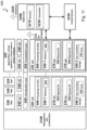
- FIGURE 8 illustrates an example wireless network, according to certain embodiments.
- the wireless network may comprise and/or interface with any type of communication, telecommunication, data, cellular, and/or radio network or other similar type of system.
- the wireless network may be configured to operate according to specific standards or other types of predefined rules or procedures.
- wireless network may implement communication standards, such as Global System for Mobile Communications (GSM), Universal Mobile Telecommunications System (UMTS), Long Term Evolution (LTE), and/or other suitable 2G, 3G, 4G, or 5G standards; wireless local area network (WLAN) standards, such as the IEEE 802.11 standards; and/or any other appropriate wireless communication standard, such as the Worldwide Interoperability for Microwave Access (WiMax), Bluetooth, Z-Wave and/or ZigBee standards.
- GSM Global System for Mobile Communications
- UMTS Universal Mobile Telecommunications System
- LTE Long Term Evolution
- WLAN wireless local area network
- WiMax Worldwide Interoperability for Microwave Access
- Bluetooth Z-Wave and/or ZigBee standards.
- Network 106 may comprise one or more backhaul networks, core networks, IP networks, public switched telephone networks (PSTNs), packet data networks, optical networks, wide-area networks (WANs), local area networks (LANs), wireless local area networks (WLANs), wired networks, wireless networks, metropolitan area networks, and other networks to enable communication between devices.
- PSTNs public switched telephone networks
- WANs wide-area networks
- LANs local area networks
- WLANs wireless local area networks
- wired networks wireless networks, metropolitan area networks, and other networks to enable communication between devices.
- Network node 160 and WD 110 comprise various components described in more detail below. These components work together to provide network node and/or wireless device functionality, such as providing wireless connections in a wireless network.
- the wireless network may comprise any number of wired or wireless networks, network nodes, base stations, controllers, wireless devices, relay stations, and/or any other components or systems that may facilitate or participate in the communication of data and/or signals whether via wired or wireless connections.
- network node refers to equipment capable, configured, arranged and/or operable to communicate directly or indirectly with a wireless device and/or with other network nodes or equipment in the wireless network to enable and/or provide wireless access to the wireless device and/or to perform other functions (e.g., administration) in the wireless network.
- network nodes include, but are not limited to, access points (APs) (e.g., radio access points), base stations (BSs) (e.g., radio base stations, Node Bs, evolved Node Bs (eNBs) and NR NodeBs (gNBs)).
- APs access points
- BSs base stations
- eNBs evolved Node Bs
- gNBs NR NodeBs
- Base stations may be categorized based on the amount of coverage they provide (or, stated differently, their transmit power level) and may then also be referred to as femto base stations, pico base stations, micro base stations, or macro base stations.
- a base station may be a relay node or a relay donor node controlling a relay.
- a network node may also include one or more (or all) parts of a distributed radio base station such as centralized digital units and/or remote radio units (RRUs), sometimes referred to as Remote Radio Heads (RRHs).
- RRUs remote radio units
- RRHs Remote Radio Heads
- Such remote radio units may or may not be integrated with an antenna as an antenna integrated radio.
- Parts of a distributed radio base station may also be referred to as nodes in a distributed antenna system (DAS).
- DAS distributed antenna system
- network nodes include multi-standard radio (MSR) equipment such as MSR BSs, network controllers such as radio network controllers (RNCs) or base station controllers (BSCs), base transceiver stations (BTSs), transmission points, transmission nodes, multi-cell/multicast coordination entities (MCEs), core network nodes (e.g., MSCs, MMEs), O&M nodes, OSS nodes, SON nodes, positioning nodes (e.g., E-SMLCs), and/or MDTs.
- MSR multi-standard radio
- RNCs radio network controllers
- BSCs base station controllers
- BTSs base transceiver stations
- transmission points transmission nodes
- MCEs multi-cell/multicast coordination entities
- core network nodes e.g., MSCs, MMEs
- O&M nodes e.g., OSS nodes, SON nodes, positioning nodes (e.g., E-SMLCs), and/or MDTs.
- network nodes may represent any suitable device (or group of devices) capable, configured, arranged, and/or operable to enable and/or provide a wireless device with access to the wireless network or to provide some service to a wireless device that has accessed the wireless network.
- network node 160 includes processing circuitry 170, device readable medium 180, interface 190, auxiliary equipment 184, power source 186, power circuitry 187, and antenna 162.
- network node 160 illustrated in the example wireless network of FIGURE 8 may represent a device that includes the illustrated combination of hardware components, other embodiments may comprise network nodes with different combinations of components (e.g., the same components, different components, fewer components, or more components). It is to be understood that a network node comprises any suitable combination of hardware and/or software needed to perform the tasks, features, functions and methods disclosed herein.
- network node 160 may comprise multiple different physical components that make up a single illustrated component (e.g., device readable medium 180 may comprise multiple separate hard drives as well as multiple RAM modules).
- network node 160 may be composed of multiple physically separate components (e.g., a NodeB component and an RNC component, or a BTS component and a BSC component, etc.), which may each have their own respective components.
- network node 160 comprises multiple separate components (e.g., BTS and BSC components)
- one or more of the separate components may be shared among several network nodes.
- a single RNC may control multiple NodeB's.
- each unique NodeB and RNC pair may in some instances be considered a single separate network node.
- network node 160 may be configured to support multiple radio access technologies (RATs).
- RATs radio access technologies
- Network node 160 may also include multiple sets of the various illustrated components for different wireless technologies integrated into network node 160, such as, for example, GSM, WCDMA, LTE, NR, WiFi, or Bluetooth wireless technologies. These wireless technologies may be integrated into the same or different chip or set of chips and other components within network node 160.
- Processing circuitry 170 is configured to perform any determining, calculating, or similar operations (e.g., certain obtaining operations) described herein as being provided by a network node, such as the scheduling operations described herein and with respect of FIGURES 2-4 .
- the operations performed by processing circuitry 170 may include processing information obtained by processing circuitry 170 by, for example, converting the obtained information into other information, comparing the obtained information or converted information to information stored in the network node, and/or performing one or more operations based on the obtained information or converted information, and as a result of said processing making a determination.
- Processing circuitry 170 may comprise a combination of one or more of a microprocessor, controller, microcontroller, central processing unit, digital signal processor, application-specific integrated circuit, field programmable gate array, or any other suitable computing device, resource, or combination of hardware, software and/or encoded logic operable to provide, either alone or in conjunction with other network node 160 components, such as device readable medium 180, network node 160 functionality.
- processing circuitry 170 may execute instructions stored in device readable medium 180 or in memory within processing circuitry 170. Such functionality may include providing any of the various wireless features, functions, or benefits discussed herein.
- processing circuitry 170 may include a system on a chip (SOC).
- SOC system on a chip
- processing circuitry 170 may include one or more of radio frequency (RF) transceiver circuitry 172 and baseband processing circuitry 174.
- radio frequency (RF) transceiver circuitry 172 and baseband processing circuitry 174 may be on separate chips (or sets of chips), boards, or units, such as radio units and digital units.
- part or all of RF transceiver circuitry 172 and baseband processing circuitry 174 may be on the same chip or set of chips, boards, or units.
- processing circuitry 170 executing instructions stored on device readable medium 180 or memory within processing circuitry 170.
- some or all of the functionality may be provided by processing circuitry 170 without executing instructions stored on a separate or discrete device readable medium, such as in a hard-wired manner.
- processing circuitry 170 can be configured to perform the described functionality. The benefits provided by such functionality are not limited to processing circuitry 170 alone or to other components of network node 160, but are enjoyed by network node 160 as a whole, and/or by end users and the wireless network generally.
- Device readable medium 180 may store any suitable instructions, data or information, including a computer program, software, an application including one or more of logic, rules, code, tables, etc. and/or other instructions capable of being executed by processing circuitry 170 and, utilized by network node 160.
- Device readable medium 180 may be used to store any calculations made by processing circuitry 170 and/or any data received via interface 190.
- processing circuitry 170 and device readable medium 180 may be considered to be integrated.
- Power circuitry 187 may comprise, or be coupled to, power management circuitry and is configured to supply the components of network node 160 with power for performing the functionality described herein. Power circuitry 187 may receive power from power source 186. Power source 186 and/or power circuitry 187 may be configured to provide power to the various components of network node 160 in a form suitable for the respective components (e.g., at a voltage and current level needed for each respective component). Power source 186 may either be included in, or external to, power circuitry 187 and/or network node 160. For example, network node 160 may be connectable to an external power source (e.g., an electricity outlet) via an input circuitry or interface such as an electrical cable, whereby the external power source supplies power to power circuitry 187.
- an external power source e.g., an electricity outlet
- power source 186 may comprise a source of power in the form of a battery or battery pack which is connected to, or integrated in, power circuitry 187.
- the battery may provide backup power should the external power source fail.
- Other types of power sources, such as photovoltaic devices, may also be used.
- network node 160 may include additional components beyond those shown in FIGURE 8 that may be responsible for providing certain aspects of the network node's functionality, including any of the functionality described herein and/or any functionality necessary to support the subject matter described herein.
- network node 160 may include user interface equipment to allow input of information into network node 160 and to allow output of information from network node 160. This may allow a user to perform diagnostic, maintenance, repair, and other administrative functions for network node 160.
- wireless device refers to a device capable, configured, arranged and/or operable to communicate wirelessly with network nodes and/or other wireless devices. Unless otherwise noted, the term WD may be used interchangeably herein with user equipment (UE). Communicating wirelessly may involve transmitting and/or receiving wireless signals using electromagnetic waves, radio waves, infrared waves, and/or other types of signals suitable for conveying information through air.
- a WD may be configured to transmit and/or receive information without direct human interaction.
- a WD may be designed to transmit information to a network on a predetermined schedule, when triggered by an internal or external event, or in response to requests from the network.
- Examples of a WD include, but are not limited to, a smart phone, a mobile phone, a cell phone, a voice over IP (VoIP) phone, a wireless local loop phone, a desktop computer, a personal digital assistant (PDA), a wireless cameras, a gaming console or device, a music storage device, a playback appliance, a wearable terminal device, a wireless endpoint, a mobile station, a tablet, a laptop, a laptop-embedded equipment (LEE), a laptop-mounted equipment (LME), a smart device, a wireless customer-premise equipment (CPE). a vehicle-mounted wireless terminal device, etc.
- VoIP voice over IP
- PDA personal digital assistant
- PDA personal digital assistant
- gaming console or device a wireless cameras
- a gaming console or device a music storage device
- a playback appliance a wearable terminal device
- a wireless endpoint a mobile station, a tablet, a laptop, a laptop-embedded equipment (LEE), a laptop
- a WD may support device-to-device (D2D) communication, for example by implementing a 3GPP standard for sidelink communication, vehicle-to-vehicle (V2V), vehicle-to-infrastructure (V2I), vehicle-to-everything (V2X) and may in this case be referred to as a D2D communication device.
- D2D device-to-device
- a WD may represent a machine or other device that performs monitoring and/or measurements and transmits the results of such monitoring and/or measurements to another WD and/or a network node.
- the WD may in this case be a machine-to-machine (M2M) device, which may in a 3GPP context be referred to as an MTC device.
- M2M machine-to-machine
- the WD may be a UE implementing the 3GPP narrow band internet of things (NB-IoT) standard. Examples of such machines or devices are sensors, metering devices such as power meters, industrial machinery, or home or personal appliances (e.g.
- a WD may represent a vehicle or other equipment that is capable of monitoring and/or reporting on its operational status or other functions associated with its operation.
- a WD as described above may represent the endpoint of a wireless connection, in which case the device may be referred to as a wireless terminal. Furthermore, a WD as described above may be mobile, in which case it may also be referred to as a mobile device or a mobile terminal.
- the wireless device may comprise a component of an aerial vehicle, such as a drone.
- the wireless device may provide command and control for the aerial vehicle.
- the wireless device may provide multimedia transmission from the aerial vehicle.
- wireless device 110 includes antenna 111, interface 114, processing circuitry 120, device readable medium 130, user interface equipment 132, auxiliary equipment 134, power source 136 and power circuitry 137.
- WD 110 may include multiple sets of one or more of the illustrated components for different wireless technologies supported by WD 110, such as, for example, GSM, WCDMA, LTE, NR, WiFi, WiMAX, or Bluetooth wireless technologies, just to mention a few. These wireless technologies may be integrated into the same or different chips or set of chips as other components within WD 110.
- Antenna 111 may include one or more antennas or antenna arrays, configured to send and/or receive wireless signals, and is connected to interface 114. In certain alternative embodiments, antenna 111 may be separate from WD 110 and be connectable to WD 110 through an interface or port. Antenna 111, interface 114, and/or processing circuitry 120 may be configured to perform any receiving or transmitting operations described herein as being performed by a WD. Any information, data and/or signals may be received from a network node and/or another WD. In some embodiments, radio front end circuitry and/or antenna 111 may be considered an interface.
- Radio front end circuitry 112 may receive digital data that is to be sent out to other network nodes or WDs via a wireless connection. Radio front end circuitry 112 may convert the digital data into a radio signal having the appropriate channel and bandwidth parameters using a combination of filters 118 and/or amplifiers 116. The radio signal may then be transmitted via antenna 111. Similarly, when receiving data, antenna 111 may collect radio signals which are then converted into digital data by radio front end circuitry 112. The digital data may be passed to processing circuitry 120. In other embodiments, the interface may comprise different components and/or different combinations of components.
- WD 110 may include regular-power radio front end circuitry and/or antenna 111 and low-power radio front end circuitry and/or antenna 111.
- the same radio circuitry may be configurable to operate as a low-power radio or a regular-power radio as needed over time.
- Processing circuitry 120 may comprise a combination of one or more of a microprocessor, controller, microcontroller, central processing unit, digital signal processor, application-specific integrated circuit, field programmable gate array, or any other suitable computing device, resource, or combination of hardware, software, and/or encoded logic operable to provide, either alone or in conjunction with other WD 110 components, such as device readable medium 130, WD 110 functionality. Such functionality may include providing any of the various wireless features or benefits discussed herein. For example, processing circuitry 120 may execute instructions stored in device readable medium 130 or in memory within processing circuitry 120 to provide the functionality disclosed herein.
- processing circuitry 120 includes one or more of RF transceiver circuitry 122, baseband processing circuitry 124, and application processing circuitry 126.
- the processing circuitry may comprise different components and/or different combinations of components.
- processing circuitry 120 of WD 110 may comprise a SOC.
- RF transceiver circuitry 122, baseband processing circuitry 124, and application processing circuitry 126 may be on separate chips or sets of chips.
- part or all of baseband processing circuitry 124 and application processing circuitry 126 may be combined into one chip or set of chips, and RF transceiver circuitry 122 may be on a separate chip or set of chips.
- part or all of RF transceiver circuitry 122 and baseband processing circuitry 124 may be on the same chip or set of chips, and application processing circuitry 126 may be on a separate chip or set of chips.
- part or all of RF transceiver circuitry 122, baseband processing circuitry 124, and application processing circuitry 126 may be combined in the same chip or set of chips.
- RF transceiver circuitry 122 may be a part of interface 114.
- RF transceiver circuitry 122 may condition RF signals for processing circuitry 120.
- processing circuitry 120 executing instructions stored on device readable medium 130, which in certain embodiments may be a computer-readable storage medium.
- some or all of the functionality may be provided by processing circuitry 120 without executing instructions stored on a separate or discrete device readable storage medium, such as in a hard-wired manner.
- processing circuitry 120 can be configured to perform the described functionality. The benefits provided by such functionality are not limited to processing circuitry 120 alone or to other components of WD 110, but are enjoyed by WD 110, and/or by end users and the wireless network generally.
- Processing circuitry 120 may be configured to perform any determining, calculating, or similar operations (e.g., certain obtaining operations) described herein as being performed by a WD. These operations, as performed by processing circuitry 120, may include processing information obtained by processing circuitry 120 by, for example, converting the obtained information into other information, comparing the obtained information or converted information to information stored by WD 110, and/or performing one or more operations based on the obtained information or converted information, and as a result of said processing making a determination.
- processing information obtained by processing circuitry 120 by, for example, converting the obtained information into other information, comparing the obtained information or converted information to information stored by WD 110, and/or performing one or more operations based on the obtained information or converted information, and as a result of said processing making a determination.
- Device readable medium 130 may be operable to store a computer program, software, an application including one or more of logic, rules, code, tables, etc. and/or other instructions capable of being executed by processing circuitry 120.
- Device readable medium 130 may include computer memory (e.g. RAM or ROM), mass storage media (e.g., a hard disk), removable storage media (e.g., a CD or a DVD), and/or any other volatile or non-volatile, non-transitory device readable and/or computer executable memory devices that store information, data, and/or instructions that may be used by processing circuitry 120.
- processing circuitry 120 and device readable medium 130 may be integrated.
- User interface equipment 132 may provide components that allow for a human user to interact with WD 110. Such interaction may be of many forms, such as visual, audial, tactile, etc. User interface equipment 132 may be operable to produce output to the user and to allow the user to provide input to WD 110. The type of interaction may vary depending on the type of user interface equipment 132 installed in WD 110. For example, if WD 110 is a smart phone, the interaction may be via a touch screen; if WD 110 is a smart meter, the interaction may be through a screen that provides usage (e.g., the number of gallons used) or a speaker that provides an audible alert (e.g., if smoke is detected).
- usage e.g., the number of gallons used
- a speaker that provides an audible alert
- User interface equipment 132 may include input interfaces, devices and circuits, and output interfaces, devices and circuits. User interface equipment 132 is configured to allow input of information into WD 110 and is connected to processing circuitry 120 to allow processing circuitry 120 to process the input information. User interface equipment 132 may include, for example, a microphone, a proximity or other sensor, keys/buttons, a touch display, one or more cameras, a USB port, or other input circuitry. User interface equipment 132 is also configured to allow output of information from WD 110, and to allow processing circuitry 120 to output information from WD 110. User interface equipment 132 may include, for example, a speaker, a display, vibrating circuitry, a USB port, a headphone interface, or other output circuitry. Using one or more input and output interfaces, devices, and circuits, of user interface equipment 132, WD 110 may communicate with end users and/or the wireless network and allow them to benefit from the functionality described herein.
- Auxiliary equipment 134 is operable to provide more specific functionality which may not be generally performed by WDs. This may comprise specialized sensors for doing measurements for various purposes, interfaces for additional types of communication such as wired communications etc. The inclusion and type of components of auxiliary equipment 134 may vary depending on the embodiment and/or scenario.
- Power source 136 may, in some embodiments, be in the form of a battery or battery pack. Other types of power sources, such as an external power source (e.g., an electricity outlet), photovoltaic devices or power cells, may also be used.
- WD 110 may further comprise power circuitry 137 for delivering power from power source 136 to the various parts of WD 110 which need power from power source 136 to carry out any functionality described or indicated herein.
- Power circuitry 137 may in certain embodiments comprise power management circuitry.
- Power circuitry 137 may additionally or alternatively be operable to receive power from an external power source; in which case WD 110 may be connectable to the external power source (such as an electricity outlet) via input circuitry or an interface such as an electrical power cable.
- Power circuitry 137 may also in certain embodiments be operable to deliver power from an external power source to power source 136. This may be, for example, for the charging of power source 136. Power circuitry 137 may perform any formatting, converting, or other modification to the power from power source 136 to make the power suitable for the respective components of WD 110 to which power is supplied.
- a wireless network such as the example wireless network illustrated in FIGURE 8 .
- the wireless network of FIGURE 8 only depicts network 106, network nodes 160 and 160b, and WDs 110, 110b, and 110c.
- a wireless network may further include any additional elements suitable to support communication between wireless devices or between a wireless device and another communication device, such as a landline telephone, a service provider, or any other network node or end device.
- network node 160 and (WD 110 are depicted with additional detail.
- the wireless network may provide communication and other types of services to one or more wireless devices to facilitate the wireless devices' access to and/or use of the services provided by, or via, the wireless network.
- the communication system 106 may itself be connected to a host computer (not shown), which may be embodied in the hardware and/or software of a standalone server, a cloud-implemented server, a distributed server or as processing resources in a server farm.
- the host computer may be under the ownership or control of a service provider or may be operated by the service provider or on behalf of the service provider.
- the communication system of FIGURE 8 as a whole enables connectivity between one of the connected WDs 110 and the host computer.
- the connectivity may be described as an over-the-top (OTT) connection.
- the host computer and the connected WDs 110 are configured to communicate data and/or signaling via the OTT connection, using an access network, a core network, any intermediate network and possible further infrastructure (not shown) as intermediaries.
- the OTT connection may be transparent in the sense that at least some of the participating communication devices through which the OTT connection passes are unaware of routing of uplink and downlink communications.
- the host computer may provide host applications which may be operable to provide a service to a remote user, such as a WD 110 connecting via an OTT connection terminating at the WD 110 and the host computer.
- the host application may provide user data which is transmitted using the OTT connection.
- the "user data" may be data and information described herein as implementing the described functionality.
- the host computer may be configured for providing control and functionality to a service provider and may be operated by the service provider or on behalf of the service provider.
- the host computer may be enabled to observe, monitor, control, transmit to and/or receive from the network node 160 and or the WD 110.
- One or more of the various embodiments in this disclosure improve the performance of OTT services provided to the WD 110 using the OTT connection. More precisely, the teachings of some of these embodiments may improve the data rate, latency, and/or power consumption and thereby provide benefits such as reduced user waiting time, relaxed restriction on file size, better responsiveness, extended battery lifetime, etc.
- FIGURE 9 is a flowchart illustrating an example method 900 in a network node, according to certain embodiments. In particular embodiments, one or more steps of FIGURE 9 may be performed by network node 160 described with respect to FIGURE 8 .
- a network node e.g., network node 160 obtains range information for a wireless device in communication with the network node.
- obtaining the range information for the wireless device comprises obtaining (e.g., calculating) a transmission RTT between the network node and the wireless device, for example, according to any of the embodiments and examples described above.
- Other embodiments may use timing advance to obtain the range information.
- the network node may determine that a UE enabled aerial vehicle may be at a distance of 200 yards from the base station based on the RTT of communications (e.g., control, multimedia, etc.) with the aerial vehicle.
- the network node obtains direction information for the wireless device.
- obtaining the direction information for the wireless device comprises one or more of determining elevation and azimuth information for the wireless device, determining one of an angle of arrival or an angle to transmission for a wireless transmission between the network node and the wireless device, determining codebook based beamforming information for the wireless device, determining reciprocity assisted beamforming information for the wireless device, and/or determining direction information according to any of the embodiments and/or examples described herein.
- the network node may determine direction information for the UE enabled aerial vehicle based on angle between two beams transmitted between the network node and the aerial vehicle.
- the network node estimates a movement of the wireless device based on the range information, the direction information, and an IMM filter.
- the IMM filter comprises a 3D constant velocity model, a 3D constant acceleration model, and a 3D constant position model.
- the network node may use the range and direction information obtained in the previous steps as input to the three-mode IMM filter described above to estimate movement of an aerial vehicle.
- estimating the movement of the wireless device is further based on a difference between an estimated altitude of the wireless device and an obtained ground altitude.
- the network node may adjust an absolute altitude value based on a terrain map of the terrain near the network node.
- the network node optionally determines that the wireless device comprises an aerial vehicle based on the estimated movement. For example, the network node can distinguish between a ground-based UE and an UE enabled aerial vehicle based on the estimated movement.
- the network node optionally signals the estimated movement of the wireless device to another network node.
- the network node signals an estimated position of the wireless device to another network node.
- the network node may signal an estimated position (e.g., based on the estimated movement) to another network node, such as a core network node, that is equipped to analyze the position/movement information and determine, for example, whether the wireless device is in or approaching restricted airspace.
- the network node optionally determines that the wireless device is in or near a restricted airspace.
- the network node may include sufficient knowledge of nearby airspace to determine whether the UE enabled aerial vehicle is in or near restricted airspace.
- the network node determines that the wireless device is in or near a restricted airspace by receiving an indication from another network node, such as a core network node.
- a core network node such as a core network node.
- the core network node described with respect to step 920 may determine that the aerial vehicle is in or near a restricted airspace and send a notification to the network node.
- the network node optionally disconnects the wireless device from the network node. For example, based on determining that the wireless device is in or near a restricted airspace (step 922), the network node may determine to disconnect the wireless device. In some embodiments, the network node is instructed to disconnect the wireless device by another network node, such as the core network node described with respect to step 920 (e.g., step 922 is not performed).
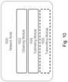
- FIGURE 10 illustrates an example network node, according to certain embodiments.
- the network node 1600 may comprise network node 160 illustrated in FIGURE 8 .
- Network node 1600 is operable to carry out the example method described with reference to FIGURE 9 and possibly any other processes or methods disclosed herein. It is also to be understood that the method of FIGURE 9 is not necessarily carried out solely by apparatus 1600. At least some operations of the method can be performed by one or more other entities, including virtual apparatuses.
- network node 1600 includes obtaining module 1602, estimating module 1604, and may include transmitting module 1606.
- obtaining module 1602 may obtain range and direction information according to any of the embodiments and examples described herein.
- Estimating module 1604 may estimate movement of a wireless device according to any of the embodiments and examples described herein.
- Transmitting module 1604 may signal information about the movement of a wireless device to another network node, according to any of the embodiments and examples described herein.
- FIGURE 11 is a schematic block diagram illustrating a virtualization environment 300 in which functions implemented by some embodiments may be virtualized.
- virtualizing means creating virtual versions of apparatuses or devices which may include virtualizing hardware platforms, storage devices and networking resources.
- virtualization can be applied to a node (e.g., a virtualized base station or a virtualized radio access node) or to a device (e.g., a UE, a wireless device or any other type of communication device) or components thereof and relates to an implementation in which at least a portion of the functionality is implemented as one or more virtual components (e.g., via one or more applications, components, functions, virtual machines or containers executing on one or more physical processing nodes in one or more networks).
- a node e.g., a virtualized base station or a virtualized radio access node
- a device e.g., a UE, a wireless device or any other type of communication device
- some or all of the functions described herein, such as the method of FIGURE 9 may be implemented as virtual components executed by one or more virtual machines implemented in one or more virtual environments 300 hosted by one or more of hardware nodes 330. Further, in embodiments in which the virtual node is not a radio access node or does not require radio connectivity (e.g., a core network node), then the network node may be entirely virtualized.
- the virtual node is not a radio access node or does not require radio connectivity (e.g., a core network node)
- the network node may be entirely virtualized.
- the functions may be implemented by one or more applications 320 (which may alternatively be called software instances, virtual appliances, network functions, virtual nodes, virtual network functions, etc.) operative to implement some of the features, functions, and/or benefits of some of the embodiments disclosed herein.
- Applications 320 are run in virtualization environment 300 which provides hardware 330 comprising processing circuitry 360 and memory 390.
- Memory 390 contains instructions 395 executable by processing circuitry 360 whereby application 320 is operative to provide one or more of the features, benefits, and/or functions disclosed herein.
- Virtualization environment 300 comprises general-purpose or special-purpose network hardware devices 330 comprising a set of one or more processors or processing circuitry 360, which may be commercial off-the-shelf (COTS) processors, dedicated Application Specific Integrated Circuits (ASICs), or any other type of processing circuitry including digital or analog hardware components or special purpose processors.
- processors or processing circuitry 360 which may be commercial off-the-shelf (COTS) processors, dedicated Application Specific Integrated Circuits (ASICs), or any other type of processing circuitry including digital or analog hardware components or special purpose processors.
- Each hardware device may comprise memory 390-1 which may be non-persistent memory for temporarily storing instructions 395 or software executed by processing circuitry 360.
- Each hardware device may comprise one or more network interface controllers (NICs) 370, also known as network interface cards, which include physical network interface 380.
- NICs network interface controllers
- Each hardware device may also include non-transitory, persistent, machine-readable storage media 390-2 having stored therein software 395 and/or instructions executable by processing circuitry 360.
- Software 395 may include any type of software including software for instantiating one or more virtualization layers 350 (also referred to as hypervisors), software to execute virtual machines 340 as well as software allowing it to execute functions, features and/or benefits described in relation with some embodiments described herein.
- Virtual machines 340 comprise virtual processing, virtual memory, virtual networking or interface and virtual storage, and may be run by a corresponding virtualization layer 350 or hypervisor. Different embodiments of the instance of virtual appliance 320 may be implemented on one or more of virtual machines 340, and the implementations may be made in different ways.
- processing circuitry 360 executes software 395 to instantiate the hypervisor or virtualization layer 350, which may sometimes be referred to as a virtual machine monitor (VMM).
- VMM virtual machine monitor
- Virtualization layer 350 may present a virtual operating platform that appears like networking hardware to virtual machine 340.
- hardware 330 may be a standalone network node with generic or specific components. Hardware 330 may comprise antenna 3225 and may implement some functions via virtualization. Alternatively, hardware 330 may be part of a larger cluster of hardware (e.g. such as in a data center or customer premise equipment (CPE)) where many hardware nodes work together and are managed via management and orchestration (MANO) 3100, which, among others, oversees lifecycle management of applications 320.
- CPE customer premise equipment
- MANO management and orchestration
- NFV network function virtualization
- NFV may be used to consolidate many network equipment types onto industry standard high-volume server hardware, physical switches, and physical storage, which can be located in data centers, and customer premise equipment.
- virtual machine 340 may be a software implementation of a physical machine that runs programs as if they were executing on a physical, non-virtualized machine.
- Each of virtual machines 340, and that part of hardware 330 that executes that virtual machine be it hardware dedicated to that virtual machine and/or hardware shared by that virtual machine with others of the virtual machines 340, forms a separate virtual network elements (VNE).
- VNE virtual network elements
- VNF Virtual Network Function
- one or more radio units 3200 that each include one or more transmitters 3220 and one or more receivers 3210 may be coupled to one or more antennas 3225.
- Radio units 3200 may communicate directly with hardware nodes 330 via one or more appropriate network interfaces and may be used in combination with the virtual components to provide a virtual node with radio capabilities, such as a radio access node or a base station.
- control system 3230 which may alternatively be used for communication between the hardware nodes 330 and radio units 3200.
- references in the specification to "one embodiment,” “an embodiment,” “an example embodiment,” etc., indicate that the embodiment described may include a particular feature, structure, or characteristic, but every embodiment may not necessarily include the particular feature, structure, or characteristic. Moreover, such phrases are not necessarily referring to the same embodiment. Further, when a particular feature, structure, or characteristic is described in connection with an embodiment, it is submitted that it is within the knowledge of one skilled in the art to implement such feature, structure, or characteristic in connection with other embodiments, whether or not explicitly described.
Landscapes
- Physics & Mathematics (AREA)
- Engineering & Computer Science (AREA)
- General Physics & Mathematics (AREA)
- Aviation & Aerospace Engineering (AREA)
- Radar, Positioning & Navigation (AREA)
- Remote Sensing (AREA)
- Electromagnetism (AREA)
- Mobile Radio Communication Systems (AREA)
- Position Fixing By Use Of Radio Waves (AREA)
Claims (14)
- Verfahren (900) zur Nutzung in einem Netzwerkknoten, wobei das Verfahren Folgendes umfasst:Einholen (912) von Bereichsinformationen für ein drahtloses Gerät in Kommunikation mit dem Netzwerkknoten;Einholen (914) von Richtungsinformationen für das drahtlose Gerät;Schätzen (916) einer Bewegung des drahtlosen Geräts basierend auf den Bereichsinformationen, den Richtungsinformationen und einem Filter zur interaktiven Mehrfachmodellierung, IMM, wobei der IMM-Filter ein konstantes, dreidimensionales, 3D, Geschwindigkeitsmodell, ein konstantes 3D-Beschleunigungsmodell und ein konstantes 3D-Positionsmodell umfasst; undBestimmen (918), dass das drahtlose Gerät ein Luftfahrzeug basierend auf der geschätzten Bewegung umfasst.
- Verfahren nach Anspruch 1, ferner umfassend Signalisieren (920) der geschätzten Bewegung des drahtlosen Geräts zu einem anderen Netzwerkknoten.
- Verfahren nach Anspruch 1 oder 2, ferner umfassend Trennen (924) des drahtlosen Geräts von dem Netzwerkknoten.
- Verfahren nach Anspruch 3, ferner umfassend Bestimmen (922), basierend auf der geschätzten Position des drahtlosen Geräts, dass sich das drahtlose Gerät in einem oder in der Nähe eines beschränkten Luftraums befindet, und wobei das Trennen des drahtlosen Geräts von dem Netzwerkknoten als Reaktion auf das Bestimmen durchgeführt wird, dass sich das drahtlose Gerät in dem oder in der Nähe des beschränkten Luftraums befindet.
- Verfahren nach einem der Ansprüche 1-4, wobei das Einholen der Bereichsinformationen für das drahtlose Gerät Berechnen einer Übertragungs-Round-Trip-Time (Übertragungs-RTT) zwischen dem Netzwerkknoten und dem drahtlosen Gerät umfasst.
- Verfahren nach einem der Ansprüche 1-5, wobei das Einholen der Richtungsinformationen für das drahtlose Gerät Bestimmen von Elevation- und Azimut-Informationen für das drahtlose Gerät umfasst.
- Verfahren nach einem der Ansprüche 1-5, wobei das Einholen der Richtungsinformationen für das drahtlose Gerät Bestimmen von einem eines Ankunftswinkels oder eines Winkels zur Übertragung für eine drahtlose Übertragung zwischen dem Netzwerkknoten und dem drahtlosen Gerät umfasst.
- Verfahren nach einem der Ansprüche 1-5, wobei das Einholen der Richtungsinformationen für das drahtlose Gerät Bestimmen eines Codebuchs basierend auf Strahlformungsinformationen für das drahtlose Gerät umfasst.
- Verfahren nach einem der Ansprüche 1-5, wobei das Einholen der Richtungsinformationen für das drahtlose Gerät Bestimmen von reziprozitätsunterstützten Strahlformungsinformationen für das drahtlose Gerät umfasst.
- Verfahren nach einem der Ansprüche 1-9, wobei das Schätzen der Bewegung des drahtlosen Geräts ferner auf einem Unterschied zwischen einer geschätzten Höhe des drahtlosen Geräts und einer eingeholten Bodenhöhe basiert.
- Verfahren nach einem der Ansprüche 1-10, wobei der Netzwerkknoten eine Basisstation umfasst.
- Netzwerkknoten (160) umfassend eine Verarbeitungsschaltung (170), die zu Folgendem betreibbar ist:Einholen von Bereichsinformationen für ein drahtloses Gerät in Kommunikation mit dem Netzwerkknoten;Einholen von Richtungsinformationen für das drahtlose Gerät; undSchätzen einer Bewegung des drahtlosen Geräts basierend auf den Bereichsinformationen, den Richtungsinformationen und einem Filter zur interaktiven Mehrfachmodellierung, IMM, wobei der IMM-Filter ein konstantes, dreidimensionales, 3D, Geschwindigkeitsmodell, ein konstantes 3D-Beschleunigungsmodell und ein konstantes 3D-Positionsmodell umfasst; undBestimmen, dass das drahtlose Gerät ein Luftfahrzeug basierend auf der geschätzten Bewegung umfasst.
- Nicht-transitorisches, computerlesbares Medium, das computerlesbaren Programmcode speichert, wobei der computerlesbare Programmcode, wenn er von einer Verarbeitungsschaltung ausgeführt wird, dazu betreibbar ist, eines der Verfahren nach den Ansprüchen 1-11 durchzuführen.
- Computerprogrammprodukt, das dazu konfiguriert ist, dazu betreibbar zu sein, eines der Verfahren nach den Ansprüchen 1-11 durchzuführen
Applications Claiming Priority (1)
| Application Number | Priority Date | Filing Date | Title |
|---|---|---|---|
| PCT/IB2020/053055 WO2021198729A1 (en) | 2020-03-31 | 2020-03-31 | Drone state estimation by single base station |
Publications (3)
| Publication Number | Publication Date |
|---|---|
| EP4127761A1 EP4127761A1 (de) | 2023-02-08 |
| EP4127761B1 true EP4127761B1 (de) | 2025-05-07 |
| EP4127761C0 EP4127761C0 (de) | 2025-05-07 |
Family
ID=70285744
Family Applications (1)
| Application Number | Title | Priority Date | Filing Date |
|---|---|---|---|
| EP20718789.9A Active EP4127761B1 (de) | 2020-03-31 | 2020-03-31 | Drohnenstatusschätzung durch eine einzelbasisstation |
Country Status (4)
| Country | Link |
|---|---|
| US (1) | US20230154342A1 (de) |
| EP (1) | EP4127761B1 (de) |
| TW (1) | TWI793495B (de) |
| WO (1) | WO2021198729A1 (de) |
Families Citing this family (4)
| Publication number | Priority date | Publication date | Assignee | Title |
|---|---|---|---|---|
| CN112738764B (zh) * | 2020-12-28 | 2021-12-24 | 北京邮电大学 | 一种基于车辆运动轨迹认知的宽带毫米波波束追踪方法 |
| US20250233636A1 (en) * | 2022-08-22 | 2025-07-17 | CesiumAstro, Inc. | Blind Direction of Arrival Estimation Systems and Methods |
| CN119545366A (zh) * | 2023-08-30 | 2025-02-28 | 华为技术有限公司 | 一种通信方法及装置 |
| CN120293151B (zh) * | 2025-06-10 | 2025-08-26 | 武汉大学 | 一种单锚点可观测的无人机自定位方法及系统 |
Citations (1)
| Publication number | Priority date | Publication date | Assignee | Title |
|---|---|---|---|---|
| EP3420742B1 (de) * | 2016-02-28 | 2019-12-04 | Qualcomm Incorporated | Unicast- und broadcast-protokoll zur drahtlosen lokalen netzwerkreichweiten- und richtungsbestimmung |
Family Cites Families (15)
| Publication number | Priority date | Publication date | Assignee | Title |
|---|---|---|---|---|
| US6338011B1 (en) * | 2000-01-11 | 2002-01-08 | Solipsys Corporation | Method and apparatus for sharing vehicle telemetry data among a plurality of users over a communications network |
| JP5439826B2 (ja) * | 2009-01-26 | 2014-03-12 | セイコーエプソン株式会社 | 位置算出方法及び位置算出装置 |
| US20170060810A1 (en) * | 2012-12-13 | 2017-03-02 | Eagle Harbor Holdings, LLC. | System and method for the operation of an automotive vehicle system with modeled sensors |
| US10348394B1 (en) * | 2014-03-14 | 2019-07-09 | Tarana Wireless, Inc. | System architecture and method for enhancing wireless networks with mini-satellites and pseudollites and adaptive antenna processing |
| US9735862B2 (en) * | 2014-09-15 | 2017-08-15 | Verizon Patent And Licensing Inc. | System and method for providing cellular signals to mobile device users travelling by air |
| WO2017165854A2 (en) * | 2016-03-24 | 2017-09-28 | CyPhy Works, Inc. | Persistent aerial reconnaissance and communication system |
| US10310498B2 (en) * | 2016-06-16 | 2019-06-04 | Echostar Technologies International Corporation | Unmanned aerial vehicle transponder systems with integrated disablement |
| US10234862B2 (en) * | 2016-07-15 | 2019-03-19 | Qualcomm Incorporated | WWAN radio link quality navigation for a drone |
| WO2018048203A1 (en) * | 2016-09-06 | 2018-03-15 | Samsung Electronics Co., Ltd. | Apparatus and method for selecting cell in wireless communication system |
| US10568063B2 (en) * | 2016-11-30 | 2020-02-18 | Cisco Technology, Inc. | Precise UAV tracking in 3-D space |
| US10127822B2 (en) * | 2017-02-13 | 2018-11-13 | Qualcomm Incorporated | Drone user equipment indication |
| US11099581B2 (en) * | 2017-09-28 | 2021-08-24 | Gopro, Inc. | Position-based control of unmanned aerial vehicles |
| CN111868802A (zh) * | 2018-01-29 | 2020-10-30 | 交互数字专利控股公司 | 用于无人驾驶航空系统业务管理(utm)系统应用的移动边缘计算(mec)部署的方法 |
| DE102018105045A1 (de) * | 2018-03-06 | 2019-09-12 | Dfs Deutsche Flugsicherung Gmbh | Luftlageinformations- und Verkehrsmanagementsystem für unbemannte und bemannte Luftfahrzeuge |
| CN111902852B (zh) * | 2018-04-05 | 2023-02-17 | 瑞典爱立信有限公司 | 用于控制未授权的空中ue的方法 |
-
2020
- 2020-03-31 EP EP20718789.9A patent/EP4127761B1/de active Active
- 2020-03-31 US US17/915,941 patent/US20230154342A1/en active Pending
- 2020-03-31 WO PCT/IB2020/053055 patent/WO2021198729A1/en not_active Ceased
-
2021
- 2021-01-08 TW TW110100744A patent/TWI793495B/zh active
Patent Citations (1)
| Publication number | Priority date | Publication date | Assignee | Title |
|---|---|---|---|---|
| EP3420742B1 (de) * | 2016-02-28 | 2019-12-04 | Qualcomm Incorporated | Unicast- und broadcast-protokoll zur drahtlosen lokalen netzwerkreichweiten- und richtungsbestimmung |
Also Published As
| Publication number | Publication date |
|---|---|
| TWI793495B (zh) | 2023-02-21 |
| EP4127761A1 (de) | 2023-02-08 |
| EP4127761C0 (de) | 2025-05-07 |
| US20230154342A1 (en) | 2023-05-18 |
| WO2021198729A1 (en) | 2021-10-07 |
| TW202139741A (zh) | 2021-10-16 |
Similar Documents
| Publication | Publication Date | Title |
|---|---|---|
| EP4127761B1 (de) | Drohnenstatusschätzung durch eine einzelbasisstation | |
| US10127822B2 (en) | Drone user equipment indication | |
| US11979851B2 (en) | User equipment kinematic state estimation | |
| EP4565891A1 (de) | Trainieren von maschinenlernpositionierungsmodellen in einem drahtlosen kommunikationsnetz | |
| US12143958B2 (en) | User equipment state estimation | |
| US12216224B2 (en) | Method and apparatus for kinematic state estimation of a user equipment | |
| US11963130B2 (en) | Device type state estimation | |
| US20220357439A1 (en) | Multi-site range rate measurement compilation in a wireless communication system | |
| US11960020B2 (en) | Sharing of user equipment states | |
| US12474432B2 (en) | User equipment (UE) movement state estimation based on measurements for two or more sites in a wireless network | |
| US20240340610A1 (en) | Network node, user equipment and methods in a wireless communications network | |
| EP4275297A1 (de) | Ephemeridendatensignalisierung mit erweiterungen zur anzeige der zellenabdeckung | |
| Ahmed et al. | Design of an Autonomous drone for IoT deployment analysis | |
| US12411221B2 (en) | User equipment two-dimensional state estimation | |
| WO2025144092A1 (en) | Methods and apparatuses for sensing in a communication network | |
| Sadhukhan et al. | 5G Positioning: A Comprehensive State-of-the-art Review with Taxonomy and Future Trends | |
| WO2025239806A1 (en) | Managing carrier phase measurement | |
| WO2025173629A1 (ja) | 情報処理装置、通信装置、情報処理方法、及び通信方法 |
Legal Events
| Date | Code | Title | Description |
|---|---|---|---|
| STAA | Information on the status of an ep patent application or granted ep patent |
Free format text: STATUS: UNKNOWN |
|
| STAA | Information on the status of an ep patent application or granted ep patent |
Free format text: STATUS: THE INTERNATIONAL PUBLICATION HAS BEEN MADE |
|
| PUAI | Public reference made under article 153(3) epc to a published international application that has entered the european phase |
Free format text: ORIGINAL CODE: 0009012 |
|
| STAA | Information on the status of an ep patent application or granted ep patent |
Free format text: STATUS: REQUEST FOR EXAMINATION WAS MADE |
|
| 17P | Request for examination filed |
Effective date: 20221017 |
|
| AK | Designated contracting states |
Kind code of ref document: A1 Designated state(s): AL AT BE BG CH CY CZ DE DK EE ES FI FR GB GR HR HU IE IS IT LI LT LU LV MC MK MT NL NO PL PT RO RS SE SI SK SM TR |
|
| DAV | Request for validation of the european patent (deleted) | ||
| DAX | Request for extension of the european patent (deleted) | ||
| GRAP | Despatch of communication of intention to grant a patent |
Free format text: ORIGINAL CODE: EPIDOSNIGR1 |
|
| STAA | Information on the status of an ep patent application or granted ep patent |
Free format text: STATUS: GRANT OF PATENT IS INTENDED |
|
| INTG | Intention to grant announced |
Effective date: 20250130 |
|
| RAP3 | Party data changed (applicant data changed or rights of an application transferred) |
Owner name: TELEFONAKTIEBOLAGET LM ERICSSON (PUBL) |
|
| GRAS | Grant fee paid |
Free format text: ORIGINAL CODE: EPIDOSNIGR3 |
|
| GRAA | (expected) grant |
Free format text: ORIGINAL CODE: 0009210 |
|
| STAA | Information on the status of an ep patent application or granted ep patent |
Free format text: STATUS: THE PATENT HAS BEEN GRANTED |
|
| AK | Designated contracting states |
Kind code of ref document: B1 Designated state(s): AL AT BE BG CH CY CZ DE DK EE ES FI FR GB GR HR HU IE IS IT LI LT LU LV MC MK MT NL NO PL PT RO RS SE SI SK SM TR |
|
| REG | Reference to a national code |
Ref country code: GB Ref legal event code: FG4D |
|
| REG | Reference to a national code |
Ref country code: CH Ref legal event code: EP |
|
| REG | Reference to a national code |
Ref country code: IE Ref legal event code: FG4D |
|
| U01 | Request for unitary effect filed |
Effective date: 20250507 |
|
| U07 | Unitary effect registered |
Designated state(s): AT BE BG DE DK EE FI FR IT LT LU LV MT NL PT RO SE SI Effective date: 20250513 |
|
| PG25 | Lapsed in a contracting state [announced via postgrant information from national office to epo] |
Ref country code: ES Free format text: LAPSE BECAUSE OF FAILURE TO SUBMIT A TRANSLATION OF THE DESCRIPTION OR TO PAY THE FEE WITHIN THE PRESCRIBED TIME-LIMIT Effective date: 20250507 |
|
| PG25 | Lapsed in a contracting state [announced via postgrant information from national office to epo] |
Ref country code: NO Free format text: LAPSE BECAUSE OF FAILURE TO SUBMIT A TRANSLATION OF THE DESCRIPTION OR TO PAY THE FEE WITHIN THE PRESCRIBED TIME-LIMIT Effective date: 20250807 Ref country code: GR Free format text: LAPSE BECAUSE OF FAILURE TO SUBMIT A TRANSLATION OF THE DESCRIPTION OR TO PAY THE FEE WITHIN THE PRESCRIBED TIME-LIMIT Effective date: 20250808 |
|
| PG25 | Lapsed in a contracting state [announced via postgrant information from national office to epo] |
Ref country code: PL Free format text: LAPSE BECAUSE OF FAILURE TO SUBMIT A TRANSLATION OF THE DESCRIPTION OR TO PAY THE FEE WITHIN THE PRESCRIBED TIME-LIMIT Effective date: 20250507 |
|
| PG25 | Lapsed in a contracting state [announced via postgrant information from national office to epo] |
Ref country code: HR Free format text: LAPSE BECAUSE OF FAILURE TO SUBMIT A TRANSLATION OF THE DESCRIPTION OR TO PAY THE FEE WITHIN THE PRESCRIBED TIME-LIMIT Effective date: 20250507 |
|
| PG25 | Lapsed in a contracting state [announced via postgrant information from national office to epo] |
Ref country code: RS Free format text: LAPSE BECAUSE OF FAILURE TO SUBMIT A TRANSLATION OF THE DESCRIPTION OR TO PAY THE FEE WITHIN THE PRESCRIBED TIME-LIMIT Effective date: 20250807 |
|
| PG25 | Lapsed in a contracting state [announced via postgrant information from national office to epo] |
Ref country code: IS Free format text: LAPSE BECAUSE OF FAILURE TO SUBMIT A TRANSLATION OF THE DESCRIPTION OR TO PAY THE FEE WITHIN THE PRESCRIBED TIME-LIMIT Effective date: 20250907 |
|
| PG25 | Lapsed in a contracting state [announced via postgrant information from national office to epo] |
Ref country code: SM Free format text: LAPSE BECAUSE OF FAILURE TO SUBMIT A TRANSLATION OF THE DESCRIPTION OR TO PAY THE FEE WITHIN THE PRESCRIBED TIME-LIMIT Effective date: 20250507 |
|
| PG25 | Lapsed in a contracting state [announced via postgrant information from national office to epo] |
Ref country code: CZ Free format text: LAPSE BECAUSE OF FAILURE TO SUBMIT A TRANSLATION OF THE DESCRIPTION OR TO PAY THE FEE WITHIN THE PRESCRIBED TIME-LIMIT Effective date: 20250507 |
|
| PG25 | Lapsed in a contracting state [announced via postgrant information from national office to epo] |
Ref country code: SK Free format text: LAPSE BECAUSE OF FAILURE TO SUBMIT A TRANSLATION OF THE DESCRIPTION OR TO PAY THE FEE WITHIN THE PRESCRIBED TIME-LIMIT Effective date: 20250507 |