EP4127563B1 - Incineration process for waste and device therefore - Google Patents
Incineration process for waste and device therefore Download PDFInfo
- Publication number
- EP4127563B1 EP4127563B1 EP21712236.5A EP21712236A EP4127563B1 EP 4127563 B1 EP4127563 B1 EP 4127563B1 EP 21712236 A EP21712236 A EP 21712236A EP 4127563 B1 EP4127563 B1 EP 4127563B1
- Authority
- EP
- European Patent Office
- Prior art keywords
- flue gases
- incinerator
- purified
- waste
- incineration process
- Prior art date
- Legal status (The legal status is an assumption and is not a legal conclusion. Google has not performed a legal analysis and makes no representation as to the accuracy of the status listed.)
- Active
Links
Images

Classifications
-
- F—MECHANICAL ENGINEERING; LIGHTING; HEATING; WEAPONS; BLASTING
- F23—COMBUSTION APPARATUS; COMBUSTION PROCESSES
- F23G—CREMATION FURNACES; CONSUMING WASTE PRODUCTS BY COMBUSTION
- F23G5/00—Incineration of waste; Incinerator constructions; Details, accessories or control therefor
- F23G5/006—General arrangement of incineration plant, e.g. flow sheets
-
- F—MECHANICAL ENGINEERING; LIGHTING; HEATING; WEAPONS; BLASTING
- F23—COMBUSTION APPARATUS; COMBUSTION PROCESSES
- F23J—REMOVAL OR TREATMENT OF COMBUSTION PRODUCTS OR COMBUSTION RESIDUES; FLUES
- F23J15/00—Arrangements of devices for treating smoke or fumes
- F23J15/02—Arrangements of devices for treating smoke or fumes of purifiers, e.g. for removing noxious material
- F23J15/04—Arrangements of devices for treating smoke or fumes of purifiers, e.g. for removing noxious material using washing fluids
-
- F—MECHANICAL ENGINEERING; LIGHTING; HEATING; WEAPONS; BLASTING
- F23—COMBUSTION APPARATUS; COMBUSTION PROCESSES
- F23L—SUPPLYING AIR OR NON-COMBUSTIBLE LIQUIDS OR GASES TO COMBUSTION APPARATUS IN GENERAL ; VALVES OR DAMPERS SPECIALLY ADAPTED FOR CONTROLLING AIR SUPPLY OR DRAUGHT IN COMBUSTION APPARATUS; INDUCING DRAUGHT IN COMBUSTION APPARATUS; TOPS FOR CHIMNEYS OR VENTILATING SHAFTS; TERMINALS FOR FLUES
- F23L7/00—Supplying non-combustible liquids or gases, other than air, to the fire, e.g. oxygen, steam
- F23L7/007—Supplying oxygen or oxygen-enriched air
-
- F—MECHANICAL ENGINEERING; LIGHTING; HEATING; WEAPONS; BLASTING
- F23—COMBUSTION APPARATUS; COMBUSTION PROCESSES
- F23G—CREMATION FURNACES; CONSUMING WASTE PRODUCTS BY COMBUSTION
- F23G2207/00—Control
- F23G2207/30—Oxidant supply
-
- F—MECHANICAL ENGINEERING; LIGHTING; HEATING; WEAPONS; BLASTING
- F23—COMBUSTION APPARATUS; COMBUSTION PROCESSES
- F23J—REMOVAL OR TREATMENT OF COMBUSTION PRODUCTS OR COMBUSTION RESIDUES; FLUES
- F23J2215/00—Preventing emissions
- F23J2215/50—Carbon dioxide
-
- F—MECHANICAL ENGINEERING; LIGHTING; HEATING; WEAPONS; BLASTING
- F23—COMBUSTION APPARATUS; COMBUSTION PROCESSES
- F23J—REMOVAL OR TREATMENT OF COMBUSTION PRODUCTS OR COMBUSTION RESIDUES; FLUES
- F23J2217/00—Intercepting solids
- F23J2217/50—Intercepting solids by cleaning fluids (washers or scrubbers)
-
- F—MECHANICAL ENGINEERING; LIGHTING; HEATING; WEAPONS; BLASTING
- F23—COMBUSTION APPARATUS; COMBUSTION PROCESSES
- F23L—SUPPLYING AIR OR NON-COMBUSTIBLE LIQUIDS OR GASES TO COMBUSTION APPARATUS IN GENERAL ; VALVES OR DAMPERS SPECIALLY ADAPTED FOR CONTROLLING AIR SUPPLY OR DRAUGHT IN COMBUSTION APPARATUS; INDUCING DRAUGHT IN COMBUSTION APPARATUS; TOPS FOR CHIMNEYS OR VENTILATING SHAFTS; TERMINALS FOR FLUES
- F23L2900/00—Special arrangements for supplying or treating air or oxidant for combustion; Injecting inert gas, water or steam into the combustion chamber
- F23L2900/07001—Injecting synthetic air, i.e. a combustion supporting mixture made of pure oxygen and an inert gas, e.g. nitrogen or recycled fumes
-
- Y—GENERAL TAGGING OF NEW TECHNOLOGICAL DEVELOPMENTS; GENERAL TAGGING OF CROSS-SECTIONAL TECHNOLOGIES SPANNING OVER SEVERAL SECTIONS OF THE IPC; TECHNICAL SUBJECTS COVERED BY FORMER USPC CROSS-REFERENCE ART COLLECTIONS [XRACs] AND DIGESTS
- Y02—TECHNOLOGIES OR APPLICATIONS FOR MITIGATION OR ADAPTATION AGAINST CLIMATE CHANGE
- Y02E—REDUCTION OF GREENHOUSE GAS [GHG] EMISSIONS, RELATED TO ENERGY GENERATION, TRANSMISSION OR DISTRIBUTION
- Y02E20/00—Combustion technologies with mitigation potential
- Y02E20/12—Heat utilisation in combustion or incineration of waste
-
- Y—GENERAL TAGGING OF NEW TECHNOLOGICAL DEVELOPMENTS; GENERAL TAGGING OF CROSS-SECTIONAL TECHNOLOGIES SPANNING OVER SEVERAL SECTIONS OF THE IPC; TECHNICAL SUBJECTS COVERED BY FORMER USPC CROSS-REFERENCE ART COLLECTIONS [XRACs] AND DIGESTS
- Y02—TECHNOLOGIES OR APPLICATIONS FOR MITIGATION OR ADAPTATION AGAINST CLIMATE CHANGE
- Y02E—REDUCTION OF GREENHOUSE GAS [GHG] EMISSIONS, RELATED TO ENERGY GENERATION, TRANSMISSION OR DISTRIBUTION
- Y02E20/00—Combustion technologies with mitigation potential
- Y02E20/32—Direct CO2 mitigation
-
- Y—GENERAL TAGGING OF NEW TECHNOLOGICAL DEVELOPMENTS; GENERAL TAGGING OF CROSS-SECTIONAL TECHNOLOGIES SPANNING OVER SEVERAL SECTIONS OF THE IPC; TECHNICAL SUBJECTS COVERED BY FORMER USPC CROSS-REFERENCE ART COLLECTIONS [XRACs] AND DIGESTS
- Y02—TECHNOLOGIES OR APPLICATIONS FOR MITIGATION OR ADAPTATION AGAINST CLIMATE CHANGE
- Y02E—REDUCTION OF GREENHOUSE GAS [GHG] EMISSIONS, RELATED TO ENERGY GENERATION, TRANSMISSION OR DISTRIBUTION
- Y02E20/00—Combustion technologies with mitigation potential
- Y02E20/34—Indirect CO2mitigation, i.e. by acting on non CO2directly related matters of the process, e.g. pre-heating or heat recovery
Definitions
- the present invention relates to an incineration process for waste, and a device for performing the incineration process.
- the invention is intended for incinerating waste or other inflammable substances in a grate incinerator, which is by far the most commonly used method for domestic waste or equivalent waste.
- the invention can also be applied in drum incinerators or fluidised bed incinerators.
- the incineration air is partly blown through the grate into the incinerator and partly over the grate into or over the burning waste in the incinerator. Said incineration air may or may not be heated.
- the incineration requires oxygen and this is supplied by air from the surroundings which chiefly consists of nitrogen (78 %) but also contains the necessary oxygen (21 %) and for the rest contains inert gases, carbon dioxide (CO 2 ) and water vapour (1 %).
- the incineration gases mostly consist of nitrogen, already present in the incineration air, but otherwise, hardly participating in the incineration process, and further of carbon dioxide (CO 2 ), water vapour (H2O) and a residual amount of unused oxygen.
- the incineration gases also contain a high number of components many of which are harmful for human health and the environment, such as acids (HCl, SO 2 , HF, etc.), nitrogen oxides (NO x ), carbon monoxide (CO) and unburned hydrocarbons, dioxins and furans, heavy metals and solid particles.
- acids HCl, SO 2 , HF, etc.
- NO x nitrogen oxides
- CO carbon monoxide
- the emission reduction i.e. the ratio of the removed quantity of a certain component to the quantity of said component in the untreated flue gases, amounts to 99% or even more in almost all cases. Only for NO x the emission reduction is less whereby 75% to 80% is already a very good result, which means that another 20% to 25% of the produced NO x is emitted.
- the energy released in waste incineration is recovered as much as possible, usually in the form of steam that is used to generate electricity in a classic Rankine steam cycle and/or for heating purposes.
- the aim is the biggest possible efficiency, i.e. to use as much energy in a useful way as possible, in other words to waste as little energy as possible.
- the biggest energy loss in waste incineration is the ⁇ flue loss', i.e. the energy leaving the flue in the flue gases.
- the present invention relates to a new incineration process for waste and by extension other fuels whereby, compared with the current state of the art:
- the nitrogen in the incineration air gives rise to the formation of NO x which, chiefly with high temperatures, is also called “thermal NO x ".
- the fuel itself i.e. the waste, also contains nitrogenous compounds which during incineration can result in NO x which is also called “fuel NO x ".
- a mixture of oxygen and an inert gas other than nitrogen can be used instead of pure oxygen.
- Flue gas recirculation i.e. a part of the produced flue gas is led back to the incinerator together with the, in this case, pure oxygen.
- Flue gas recirculation or FGR is a known and regularly applied method, but certainly not always, in traditional waste incineration and has a favourable influence on the thermal efficiency of the installation. FGR would also limit NO x formation.
- the purpose of the present invention is to provide a solution to the aforementioned and other disadvantages by providing in an incineration process, allowing the heat recovery to be increased, the CO2 emission to be prevented entirely or almost entirely and the amount of flue gas to be reduced by many factors.
- the present invention relates to a classic grate incinerator whereby the incineration air will be replaced by a mixture of pure oxygen and recirculated, purified and dewatered flue gas, more than half of which consists of CO 2 .
- the energy balance shows that the steam cycle is considerably more efficient, in the example (in terms of figures) this is 7.5%, because the flue loss is less. Furthermore, the flue gas flow through the boiler is lower such that the steam boiler, the fans, pipes, etc. can be smaller as well, and therefore the investment cost is lower.
- the pure oxygen required for this process is made on site with • Electrolysis During electrolysis, pure water is separated into oxygen gas and hydrogen gas. This known procedure consumes a huge amount of electrical energy, far more than the waste incineration installation produces.
- the first goal of electrolysis is making hydrogen gas, the oxygen then being a 'by-product'.
- electrolysis is used to generate the required oxygen for the incineration process.
- the invention also relates to a device according to claim 9 for performing the incineration process.
- the device comprises an incinerator with a feed for the waste to be incinerated, a feed for a mixture of pure oxygen and recycled, purified and dewatered flue gas, a discharge for bottom ashes and a discharge for hot flue gases, and whereby the device also comprises an electrolysis device, with which the water that was recovered from the flue gas purification installation is separated into pure oxygen and pure hydrogen, whereby the pure oxygen is led to the incinerator after being mixed with recycled, purified and dewatered flue gases and introduced into the incinerator to maintain the incineration.
- the calculations show that sufficient water is recovered from the flue gases to produce the necessary oxygen. The water does have to be completely purified and demineralised. An installation of the desired size does not yet exist.
- the discharge for hot flue gases in the device can be connected to the feed of a steam boiler in which the hot flue gases are cooled with water with formation of steam and are discharged as cooled flue gases, whereby the formed steam is converted into electric power in a Rankine cycle.
- the flue gases of the waste incineration rich in CO 2 are combined with the hydrogen gas produced by electrolysis to make a useful chemical substance using existing technology.
- An example is the synthesis of methanol (CH 3 OH). This is a known fuel but also a basic product for the chemical industry.
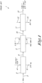
- FIG 1 schematically shows a flow diagram 1 of a traditional incineration process in a grate incinerator 2 whereby the waste 3 is fed to the grate incinerator 2 and together with incineration air 4, i.e. ambient air is mixed and incinerated, resulting in, on the one hand, hot flue gases 5 and on the other hand, in incineration residues 6 such as bottom ashes.
- the hot flue gases 5 are cooled in a steam boiler 7 in which water 8 is converted into steam 9 and whereby a part of the energy is recovered that is released during the incineration.
- the cooled flue gases 10 are purified in a purification step 11 by means of chemicals 12, with the formation of purified flue gases 13 which are discharged into the atmosphere, and residues 14 of the flue gas purification.
- the figure specifies the obtained quantities starting from 1 tonne per hour (TPH) of waste 3 processing, and the supply of 4.87 tonnes ambient air 4, resulting in 214 kg bottom ashes 6, and 2.32 tonnes of steam 9 in the steam boiler 7, which recovers 492 kWh energy from the cooled flue gases 10.
- Said cooled flue gases 10 are purified with chemicals 12 whereby 25.1 kg residue 14 of the flue gas purification 11 is formed, and after which 5.99 tonnes of flue gas 13 are discharged into the atmosphere.
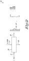
- Figure 2 schematically shows a flow diagram 15 of a hypothetical but unfeasible incineration process of waste 3 in an incinerator 16, whereby the incineration air from the environment would be replaced by pure oxygen 17 (99% pure).
- the temperature of the incinerator 16 would hereby increase to an untenable temperature in excess of 2000 °C, resulting in a melted incinerator and incineration residues 18 and the theoretical flue gases 19 would only consist of water vapour, CO 2 and a small percentage of pollutants such as acids, NOx, CO and particles.
- the total flue gas flow would be much less, i.e. 1,500 Nm3 per tonne of waste, and the thermal efficiency would be better due to far less flue loss.
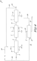
- Figure 3 schematically shows a flow diagram 20 of an incineration process of waste 3 in a classic grate incinerator 21, whereby a mixture 22 of pure oxygen 23 and of recirculated, purified and dewatered flue gas 24 is added to the incinerator, more than half of which consists of CO 2 .
- 1 tonne of waste requires 0.63 tonne of pure oxygen O 2 whereas the flue gases at the exit 24 amount to less than 0.8 tonne or less than 15% of the quantity of flue gases produced in a traditional incineration process with incineration air from the environment.
- the incineration process converts the waste 3 into hot flue gases 5 and bottom ashes 6, after which the hot flue gases are cooled in a steam boiler 7 in which water 8 is converted into steam 9.
- the cooled flue gases 10 are purified in a flue gas purification system 11 with condensing scrubber by adding chemicals 12, and with the formation of residues 14 of flue gases.
- the energy balance shows that the steam cycle is considerably more efficient (now 7.5 % more) and that the flue loss is less, such that the whole installation can be sized smaller.
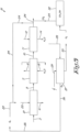
- Figure 4 schematically shows a flow diagram 25 of a waste incineration process for an incinerator whereby a mixture of pure oxygen and recycled, purified and dewatered flue gas is supplied to the incinerator and whereby the pure oxygen, necessary for the incineration process, is produced locally in an electrolysis device, which separates water recovered from purifying the cooled flue gases into hydrogen (30) and oxygen (26).
- the electrolysis device 27 uses renewable energy 29 such as solar and/or wind energy to produce oxygen 26, whereby hydrogen 30 is also produced as a by-product, which can be sold, or in a second variant of the incineration process according to the invention can also be utilised on site.
- Figure 5 shows a flow diagram 31 of the incineration process according to the invention, whereby in this case the flue gases 24 of the waste incineration rich in CO 2 , are partly combined with the hydrogen gas H 2 30 that was produced via electrolysis of water 28 in an electrolysis device 29 and this in a methanol synthesis device 32, with formation of methanol CH 3 OH, said substance itself being a known fuel but also a basic product usable for the chemical industry.
- the operation of an incineration process 20 of waste 3 according to the invention in a classic grate incinerator 21, is very simple and as follows.
- the waste 3 is incinerated in an incinerator 21 to which a mixture of pure oxygen and recycled, purified and dewatered flue gas is supplied, whereby more than half of the supplied mixture consists of CO 2 .
- the incineration of the waste 3 leads to the formation of hot flue gases 5, and bottom ashes 6 which remain at the bottom of the incinerator.
- the hot flue gases 5 are cooled in a steam boiler in which water 8 is heated to steam 9 and whereby a part of the energy supplied to the flue gases is recovered.
- the cooled flue gases 10 are fed to a flue gas purification installation 11 which by means of chemicals 12 and a condensing scrubber purifies the flue gases 10 to purified flue gas 24, after which said purified flue gas is partly discharged into the atmosphere, but is also partly recycled as purified and dewatered flue gas 24 which consists chiefly of CO 2 and is mixed with pure oxygen 23 (99%) and returned to the incinerator to allow incineration with oxygen in the incinerator at applicable temperatures.
- the pure oxygen 26 required for the incineration process is produced locally in an electrolysis device 27, which separates water 28 recovered from purifying the cooled flue gases 10 into hydrogen 30 and oxygen 26, using renewable energy 29 such as solar and/or wind energy, whereby the necessary pure oxygen 26 is supplied to the incineration process, and the formed hydrogen 30 can be sold as industrial gas, or utilised on site, by letting it react with a part of the purified and dewatered flue gas 24 in a local synthesis device where organic products are formed such as, in this case, methanol in a methanol synthesis device.
- the formed methanol can be used both as fuel or be utilised as raw material for the chemical industry.
- reaction products from the hydrogen and the dewatered and purified flue gas 24 produced on site are not limited to methanol, but other reaction products are also possible, with or without the use of catalysts.
Landscapes
- Engineering & Computer Science (AREA)
- Mechanical Engineering (AREA)
- General Engineering & Computer Science (AREA)
- Chemical & Material Sciences (AREA)
- Combustion & Propulsion (AREA)
- Air Supply (AREA)
- Gasification And Melting Of Waste (AREA)
- Processing Of Solid Wastes (AREA)
Description
- The present invention relates to an incineration process for waste, and a device for performing the incineration process.
- In particular, the invention is intended for incinerating waste or other inflammable substances in a grate incinerator, which is by far the most commonly used method for domestic waste or equivalent waste. However, the invention can also be applied in drum incinerators or fluidised bed incinerators.
- It is known that for processing general waste worldwide the most commonly used method that remains as the only feasible option is incineration with energy recovery.
- Traditionally the waste is incinerated in a grate incinerator in a large enclosed chamber, the floor of which consists of a "grate". This grate which bears the burning waste moves the waste from the feed side up to the discharge side of the incineration residues, i.e. bottom ashes or slags.
- The incineration air is partly blown through the grate into the incinerator and partly over the grate into or over the burning waste in the incinerator. Said incineration air may or may not be heated.
- The incineration requires oxygen and this is supplied by air from the surroundings which chiefly consists of nitrogen (78 %) but also contains the necessary oxygen (21 %) and for the rest contains inert gases, carbon dioxide (CO2) and water vapour (1 %).
- The incineration gases mostly consist of nitrogen, already present in the incineration air, but otherwise, hardly participating in the incineration process, and further of carbon dioxide (CO2), water vapour (H2O) and a residual amount of unused oxygen.
- The incineration gases also contain a high number of components many of which are harmful for human health and the environment, such as acids (HCl, SO2, HF, etc.), nitrogen oxides (NOx), carbon monoxide (CO) and unburned hydrocarbons, dioxins and furans, heavy metals and solid particles.
- These components are an inevitable complication of waste incineration but there are sufficient techniques to reduce the emissions of said components to a very low level. The emission reduction, i.e. the ratio of the removed quantity of a certain component to the quantity of said component in the untreated flue gases, amounts to 99% or even more in almost all cases. Only for NOx the emission reduction is less whereby 75% to 80% is already a very good result, which means that another 20% to 25% of the produced NOx is emitted.
- In recent years, global warming has become an important social and political issue. This warming is caused mostly by the increasing concentration of CO2 ("greenhouse gas") in the atmosphere, but also a number of other substances such as methane. This is the result of human activities such as traffic, heating of buildings, electricity generation, industry, and the like. The flue gases of waste incineration contain approximately 9 vol% CO2 on average. The existing techniques to capture said CO2 are cumbersome and expensive.
- The energy released in waste incineration is recovered as much as possible, usually in the form of steam that is used to generate electricity in a classic Rankine steam cycle and/or for heating purposes. The aim is the biggest possible efficiency, i.e. to use as much energy in a useful way as possible, in other words to waste as little energy as possible. The biggest energy loss in waste incineration is the `flue loss', i.e. the energy leaving the flue in the flue gases.
- The present invention relates to a new incineration process for waste and by extension other fuels whereby, compared with the current state of the art:
- None or hardly any CO2 is emitted;
- More energy can be recovered;
- The formation of NOx is substantially lower;
- The amount of flue gases is many times less.
- In the current state of the art the waste incineration in a grate incinerator goes through three main processes (see also
Fig. 1 ): - 1. An incineration process in which the waste is fed to the incinerator and is mixed and incinerated together with incineration air, resulting on the one hand in hot flue gases and on the other hand in incineration residues;
- 2. A cooling process in which the hot flue gases are cooled in a steam boiler and the energy released during the incineration is recovered;
- 3. A purification process in which the cooled flue gases are purified before they are discharged into the atmosphere.
- However, the mass and energy balance of this sort of known waste incineration in a grate incinerator is unfavourable. Per tonne or per 1000 kg of waste, approximately 5 tonnes of air are needed and approximately 6 tonnes of flue gases are produced. This large quantity is the result of the fact that the incineration air consists of inert nitrogen for the most part, which does not participate or hardly participates in the incineration processes, but does have to be heated and cooled again. The whole installation must therefore be sized for a flow of gas which for the most parts consists of inert nitrogen ballast.
- The nitrogen in the incineration air gives rise to the formation of NOx which, chiefly with high temperatures, is also called "thermal NOx". The fuel itself, i.e. the waste, also contains nitrogenous compounds which during incineration can result in NOx which is also called "fuel NOx".
- According to most specialised literature "fuel NOx" is the dominant form in waste incineration, particularly with moderate temperatures. The typical NOx concentration of the flue gases at the exit of the incinerator amounts to 400 mg/Nm3 under reference circumstances, whereas the European directives lay down a maximum of 200 mg/Nm3 in the flue and even lower standards, to 100 mg or 70 mg, are imposed in the permit of many installations. To achieve said lower values, so-called de-NOx-installations are needed, which exist in two variants: at high temperature without catalyst (SNCR) or at lower temperature but then with catalyst (SCR).
- The foregoing shows that a logical step would be to avoid the nitrogen in the incineration air by working with pure oxygen, which is an industrial gas that is applied on a large scale in, for example, the steel industry. Although this is theoretically possible, the calculations show that the temperature in the incinerator, even at a low incineration value of the waste, increases to very high values to more than 2000°C.
- This is much too high for a grate incinerator. It would in any case result in the formation of melted incineration residues and clinkers. When pure oxygen is used the theoretical flue gases only consist of water vapour, CO2 and a small percentage of pollutants as with classic waste incineration i.e. acids, NOx, CO, and particles (see also
Figure 2 ). - To limit the temperature in the incinerator, a mixture of oxygen and an inert gas other than nitrogen can be used instead of pure oxygen.
- An obvious option is flue gas recirculation, i.e. a part of the produced flue gas is led back to the incinerator together with the, in this case, pure oxygen. Flue gas recirculation or FGR is a known and regularly applied method, but certainly not always, in traditional waste incineration and has a favourable influence on the thermal efficiency of the installation. FGR would also limit NOx formation.
- In the concept with pure oxygen, the flue gases contain a lot of water vapour as well as pollutants. They can be removed with classic techniques of flue gas purification and flue gas condensation. In the latter the flue gases are cooled to below their saturation temperature, typically 65°C. A lot of water is recovered in this way on the one hand, which still needs to be purified, but on the other hand a lot of heat is also recovered. This, however, concerns heat at low temperature, only suitable for heating buildings for example.
EP 1 107 833 A1claim 1. - The purpose of the present invention is to provide a solution to the aforementioned and other disadvantages by providing in an incineration process, allowing the heat recovery to be increased, the CO2 emission to be prevented entirely or almost entirely and the amount of flue gas to be reduced by many factors.
- To this end the present invention relates to a classic grate incinerator whereby the incineration air will be replaced by a mixture of pure oxygen and recirculated, purified and dewatered flue gas, more than half of which consists of CO2.
- The mass and energy balance of said incineration process according to the invention in a grate incinerator is far more favourable.
- 1 tonne of waste requires 0.63 tonnes of pure O2. The flue gases at the exit amount to less than 0.8 tonne, i.e. less than 15% of what is released with the traditional state of the art and for 90% consist of CO2. It has thus become very simple to capture and store said CO2 ('Carbon Capture and Storage' of CCS) or to use it ('Carbon Capture and Utilisation' of CCU). However, CCS and CCU are existing concepts which demand a lot of energy and resources. In the present invention they become self-evident.
- The energy balance shows that the steam cycle is considerably more efficient, in the example (in terms of figures) this is 7.5%, because the flue loss is less. Furthermore, the flue gas flow through the boiler is lower such that the steam boiler, the fans, pipes, etc. can be smaller as well, and therefore the investment cost is lower.
- The pure oxygen required for this process is made on site with • Electrolysis During electrolysis, pure water is separated into oxygen gas and hydrogen gas. This known procedure consumes a huge amount of electrical energy, far more than the waste incineration installation produces. The first goal of electrolysis is making hydrogen gas, the oxygen then being a 'by-product'.
- In the present invention electrolysis is used to generate the required oxygen for the incineration process.
- The invention also relates to a device according to
claim 9 for performing the incineration process. The device comprises an incinerator with a feed for the waste to be incinerated, a feed for a mixture of pure oxygen and recycled, purified and dewatered flue gas, a discharge for bottom ashes and a discharge for hot flue gases, and whereby the device also comprises an electrolysis device, with which the water that was recovered from the flue gas purification installation is separated into pure oxygen and pure hydrogen, whereby the pure oxygen is led to the incinerator after being mixed with recycled, purified and dewatered flue gases and introduced into the incinerator to maintain the incineration. The calculations show that sufficient water is recovered from the flue gases to produce the necessary oxygen. The water does have to be completely purified and demineralised. An installation of the desired size does not yet exist. - The discharge for hot flue gases in the device can be connected to the feed of a steam boiler in which the hot flue gases are cooled with water with formation of steam and are discharged as cooled flue gases, whereby the formed steam is converted into electric power in a Rankine cycle. In the present invention the flue gases of the waste incineration rich in CO2 are combined with the hydrogen gas produced by electrolysis to make a useful chemical substance using existing technology. An example is the synthesis of methanol (CH3OH). This is a known fuel but also a basic product for the chemical industry.
- When the synthesis of methanol is combined with the waste incineration installation, interesting synergies are possible, because the synthesis consumes steam but also produces energy. Such methanol synthesis installations exist on a sufficiently large scale.
- With the intention of better showing the characteristics of the invention, a few preferred embodiments of an incineration process according to the invention are described hereinafter by way of an example, without any limiting nature, with reference to the accompanying drawings, wherein:
-
Figure 1 schematically shows a flow diagram of a traditional incineration process in a grate incinerator; -
figure 2 schematically shows a flow diagram of a hypothetical incineration process with pure oxygen; -
figure 3 schematically shows a flow diagram of an incineration process in a grate incinerator; -
figure 4 schematically shows a flow diagram of the incineration process with electrolysis of water; -
figure 5 schematically shows a flow diagram according to the invention. -
Figure 1 schematically shows a flow diagram 1 of a traditional incineration process in agrate incinerator 2 whereby the waste 3 is fed to thegrate incinerator 2 and together with incineration air 4, i.e. ambient air is mixed and incinerated, resulting in, on the one hand,hot flue gases 5 and on the other hand, in incineration residues 6 such as bottom ashes. Thehot flue gases 5 are cooled in a steam boiler 7 in which water 8 is converted intosteam 9 and whereby a part of the energy is recovered that is released during the incineration. The cooledflue gases 10 are purified in a purification step 11 by means ofchemicals 12, with the formation of purifiedflue gases 13 which are discharged into the atmosphere, andresidues 14 of the flue gas purification. The figure specifies the obtained quantities starting from 1 tonne per hour (TPH) of waste 3 processing, and the supply of 4.87 tonnes ambient air 4, resulting in 214 kg bottom ashes 6, and 2.32 tonnes ofsteam 9 in the steam boiler 7, which recovers 492 kWh energy from the cooledflue gases 10. Said cooledflue gases 10 are purified withchemicals 12 whereby 25.1kg residue 14 of the flue gas purification 11 is formed, and after which 5.99 tonnes offlue gas 13 are discharged into the atmosphere. -
Figure 2 schematically shows a flow diagram 15 of a hypothetical but unfeasible incineration process of waste 3 in an incinerator 16, whereby the incineration air from the environment would be replaced by pure oxygen 17 (99% pure). The temperature of the incinerator 16 would hereby increase to an untenable temperature in excess of 2000 °C, resulting in a melted incinerator and incineration residues 18 and thetheoretical flue gases 19 would only consist of water vapour, CO2 and a small percentage of pollutants such as acids, NOx, CO and particles. The total flue gas flow would be much less, i.e. 1,500 Nm3 per tonne of waste, and the thermal efficiency would be better due to far less flue loss. -
Figure 3 schematically shows a flow diagram 20 of an incineration process of waste 3 in aclassic grate incinerator 21, whereby amixture 22 ofpure oxygen 23 and of recirculated, purified and dewateredflue gas 24 is added to the incinerator, more than half of which consists of CO2. 1 tonne of waste requires 0.63 tonne of pure oxygen O2 whereas the flue gases at theexit 24 amount to less than 0.8 tonne or less than 15% of the quantity of flue gases produced in a traditional incineration process with incineration air from the environment. - Furthermore, 90% of the flue gases consist of CO2 which is better suited to capturing and storing or utilising said CO2. The incineration process converts the waste 3 into
hot flue gases 5 and bottom ashes 6, after which the hot flue gases are cooled in a steam boiler 7 in which water 8 is converted intosteam 9. The cooledflue gases 10 are purified in a flue gas purification system 11 with condensing scrubber by addingchemicals 12, and with the formation ofresidues 14 of flue gases. The energy balance shows that the steam cycle is considerably more efficient (now 7.5 % more) and that the flue loss is less, such that the whole installation can be sized smaller. -
Figure 4 schematically shows a flow diagram 25 of a waste incineration process for an incinerator whereby a mixture of pure oxygen and recycled, purified and dewatered flue gas is supplied to the incinerator and whereby the pure oxygen, necessary for the incineration process, is produced locally in an electrolysis device, which separates water recovered from purifying the cooled flue gases into hydrogen (30) and oxygen (26). - Calculations show that
sufficient water 28 is recovered from purifying the cooledflue gases 10 to produce the necessary oxygen, provided that the water is completely purified and demineralised. Theelectrolysis device 27 uses renewable energy 29 such as solar and/or wind energy to produceoxygen 26, wherebyhydrogen 30 is also produced as a by-product, which can be sold, or in a second variant of the incineration process according to the invention can also be utilised on site. -
Figure 5 shows a flow diagram 31 of the incineration process according to the invention, whereby in this case theflue gases 24 of the waste incineration rich in CO2, are partly combined with thehydrogen gas H 2 30 that was produced via electrolysis ofwater 28 in an electrolysis device 29 and this in amethanol synthesis device 32, with formation of methanol CH3OH, said substance itself being a known fuel but also a basic product usable for the chemical industry. - The operation of an
incineration process 20 of waste 3 according to the invention in aclassic grate incinerator 21, is very simple and as follows. The waste 3 is incinerated in anincinerator 21 to which a mixture of pure oxygen and recycled, purified and dewatered flue gas is supplied, whereby more than half of the supplied mixture consists of CO2. - The incineration of the waste 3 leads to the formation of
hot flue gases 5, and bottom ashes 6 which remain at the bottom of the incinerator. Thehot flue gases 5 are cooled in a steam boiler in which water 8 is heated tosteam 9 and whereby a part of the energy supplied to the flue gases is recovered. The cooledflue gases 10 are fed to a flue gas purification installation 11 which by means ofchemicals 12 and a condensing scrubber purifies theflue gases 10 to purifiedflue gas 24, after which said purified flue gas is partly discharged into the atmosphere, but is also partly recycled as purified and dewateredflue gas 24 which consists chiefly of CO2 and is mixed with pure oxygen 23 (99%) and returned to the incinerator to allow incineration with oxygen in the incinerator at applicable temperatures. - In the incineration process according to the invention the
pure oxygen 26 required for the incineration process is produced locally in anelectrolysis device 27, which separateswater 28 recovered from purifying the cooledflue gases 10 intohydrogen 30 andoxygen 26, using renewable energy 29 such as solar and/or wind energy, whereby the necessarypure oxygen 26 is supplied to the incineration process, and the formedhydrogen 30 can be sold as industrial gas, or utilised on site, by letting it react with a part of the purified and dewateredflue gas 24 in a local synthesis device where organic products are formed such as, in this case, methanol in a methanol synthesis device. The formed methanol can be used both as fuel or be utilised as raw material for the chemical industry. - It goes without saying that the reaction products from the hydrogen and the dewatered and purified
flue gas 24 produced on site are not limited to methanol, but other reaction products are also possible, with or without the use of catalysts.
Claims (13)
- Waste incineration process (20) for an incinerator (21) for incinerating waste (3), wherein characterized in that a mixture (22) of pure oxygen (23) and recycled, purified and dewatered flue gas (24) is supplied to the incinerator (21) characterised in that the pure oxygen (26), necessary for the incineration process, is produced locally in an electrolysis device (27) which separates water (28) recovered from purifying the cooled flue gases (10) into hydrogen (30) and oxygen (26), and the hydrogen (30) formed in the electrolysis device (27) is also utilised on site, by letting the formed hydrogen (30) react, with a part of the purified and dewatered flue gas (24) in a local synthesis device (32).
- Waste incineration process according to claim 1, characterised in that more than half of the supplied mixture (22) of pure oxygen (23) and recycled flue gas (24) consists of CO2.
- Waste incineration process (20) according to claim 1, characterised in that the incineration process converts waste (3) into hot flue gases (5) which are cooled in a steam boiler (7) for the production of steam (9), from which electrical energy is generated by means of a Rankine cycle.
- Waste incineration process (20) according to claim 3, characterised in that the cooled flue gases (10) are purified and dewatered in a flue gas purification system (11) with condensing scrubber by adding chemicals (12).
- Waste incineration process (20) according to claim 4, characterised in that the cooled, purified and dewatered flue gases (24) are partly recycled to the incinerator (21).
- Waste incineration process according to claim 1, characterised in that the electrolysis device (27) uses renewable energy (29) such as solar and/or wind energy, whereby the pure oxygen, necessary for the incineration process is supplied to the incinerator, and the formed hydrogen (30) is sold as industrial gas.
- Waste incineration process according to any of the previous claims 7, characterised in that organic products are formed in the synthesis device (32).
- Waste incineration process according to claim 7, characterised in that the formed organic product is methanol, whereby the formed methanol can be used both as fuel and as chemical raw material for the chemical industry.
- Device for performing the waste incineration process described in claim 1, wherein the device comprises an incinerator (21) with a feed for the waste to be incinerated (3), a feed for a mixture (22) of pure oxygen (23) and recycled, purified and dewatered flue gas (24), and a discharge for bottom ashes (6) and a discharge for hot flue gases (5), and wherein the device also comprises an electrolysis device (27), configured to separate the water (28) that was recovered from the flue gas purification installation into pure oxygen (26) and pure hydrogen (30), whereby the pure oxygen (26) is led to the incinerator (21) after being mixed with recycled, purified and dewatered flue gases (24), to maintain the incineration, wherein the device also comprises a synthesis device (32) to which pure hydrogen (30) from the electrolysis device (27) is supplied, and recycled, purified and dewatered flue gases (24) react with the formation of reaction products.
- Device according to claim 9, wherein the discharge for hot flue gases (5) is connected to a feed of a steam boiler (7) configured to cool the hot flue gases with water (8) with the formation of steam (9) and to discharge them as cooled flue gases (10), whereby the device is configured to convert the formed steam (9) into electric power in a Rankine cycle.
- Device according to claim 10, wherein the discharge of cooled flue gases (10) is connected to the feed of a flue gas purification installation (11) with a condensing scrubber, in which chemicals (12) are added to the cooled flue gases (10) and the cooled flue gases are purified to become purified and dewatered flue gases (24) that are led to a discharge.
- Device according to claim 11, wherein the discharge partly discharges the purified and dewatered flue gases (24) into the atmosphere, and partly recycles them by feeding this part back to the incinerator (21), and after admixture of pure oxygen (23), introducing it into the incinerator (21) to maintain the incineration in the incinerator.
- Device according to any of the claims 9 to 12, wherein the synthesis device (32) is a methanol synthesis device that produces methanol.
Applications Claiming Priority (2)
| Application Number | Priority Date | Filing Date | Title |
|---|---|---|---|
| BE20205221A BE1028186B1 (en) | 2020-04-03 | 2020-04-03 | Waste incineration process |
| PCT/IB2021/052034 WO2021198819A1 (en) | 2020-04-03 | 2021-03-11 | Incineration process for waste and device therefore |
Publications (3)
| Publication Number | Publication Date |
|---|---|
| EP4127563A1 EP4127563A1 (en) | 2023-02-08 |
| EP4127563C0 EP4127563C0 (en) | 2024-10-30 |
| EP4127563B1 true EP4127563B1 (en) | 2024-10-30 |
Family
ID=70456688
Family Applications (1)
| Application Number | Title | Priority Date | Filing Date |
|---|---|---|---|
| EP21712236.5A Active EP4127563B1 (en) | 2020-04-03 | 2021-03-11 | Incineration process for waste and device therefore |
Country Status (5)
| Country | Link |
|---|---|
| EP (1) | EP4127563B1 (en) |
| BE (1) | BE1028186B1 (en) |
| ES (1) | ES3005096T3 (en) |
| PL (1) | PL4127563T3 (en) |
| WO (1) | WO2021198819A1 (en) |
Citations (6)
| Publication number | Priority date | Publication date | Assignee | Title |
|---|---|---|---|---|
| WO1999051367A1 (en) | 1998-04-06 | 1999-10-14 | Minergy Corp. | Closed-cycle waste combustion |
| US20030171635A1 (en) * | 2001-02-26 | 2003-09-11 | Tamas Bereczky | Method for treatment of hazardous fluid organic waste materials |
| DE102012214907A1 (en) | 2012-08-22 | 2013-10-24 | Siemens Aktiengesellschaft | Operating steam plant for producing electrical energy by combustion process, comprises operating electrolysis unit to provide hydrogen and oxygen, and operating methanation unit under consumption of hydrogen and carbon dioxide |
| US20140288195A1 (en) | 2011-11-04 | 2014-09-25 | Commissariat A L'energie Atomique Et Aux Energies Alternatives | Process for the thermochemical conversion of a carbon-based feedstock to synthesis gas containing predominantly h2 and co |
| WO2017060704A1 (en) | 2015-10-06 | 2017-04-13 | Heptonstall William B | Sustainable energy system |
| WO2020030470A1 (en) | 2018-08-10 | 2020-02-13 | Siemens Aktiengesellschaft | Providing carbon dioxide by means of oxygen-based combustion |
Family Cites Families (2)
| Publication number | Priority date | Publication date | Assignee | Title |
|---|---|---|---|---|
| US5309850A (en) * | 1992-11-18 | 1994-05-10 | The Babcock & Wilcox Company | Incineration of hazardous wastes using closed cycle combustion ash vitrification |
| US8038744B2 (en) * | 2006-10-02 | 2011-10-18 | Clark Steve L | Reduced-emission gasification and oxidation of hydrocarbon materials for hydrogen and oxygen extraction |
-
2020
- 2020-04-03 BE BE20205221A patent/BE1028186B1/en active IP Right Grant
-
2021
- 2021-03-11 ES ES21712236T patent/ES3005096T3/en active Active
- 2021-03-11 EP EP21712236.5A patent/EP4127563B1/en active Active
- 2021-03-11 WO PCT/IB2021/052034 patent/WO2021198819A1/en not_active Ceased
- 2021-03-11 PL PL21712236.5T patent/PL4127563T3/en unknown
Patent Citations (7)
| Publication number | Priority date | Publication date | Assignee | Title |
|---|---|---|---|---|
| WO1999051367A1 (en) | 1998-04-06 | 1999-10-14 | Minergy Corp. | Closed-cycle waste combustion |
| EP1107833B1 (en) * | 1998-04-06 | 2003-11-12 | Minergy Corp. | Closed-cycle waste combustion |
| US20030171635A1 (en) * | 2001-02-26 | 2003-09-11 | Tamas Bereczky | Method for treatment of hazardous fluid organic waste materials |
| US20140288195A1 (en) | 2011-11-04 | 2014-09-25 | Commissariat A L'energie Atomique Et Aux Energies Alternatives | Process for the thermochemical conversion of a carbon-based feedstock to synthesis gas containing predominantly h2 and co |
| DE102012214907A1 (en) | 2012-08-22 | 2013-10-24 | Siemens Aktiengesellschaft | Operating steam plant for producing electrical energy by combustion process, comprises operating electrolysis unit to provide hydrogen and oxygen, and operating methanation unit under consumption of hydrogen and carbon dioxide |
| WO2017060704A1 (en) | 2015-10-06 | 2017-04-13 | Heptonstall William B | Sustainable energy system |
| WO2020030470A1 (en) | 2018-08-10 | 2020-02-13 | Siemens Aktiengesellschaft | Providing carbon dioxide by means of oxygen-based combustion |
Non-Patent Citations (1)
| Title |
|---|
| KITTO J B , STULTZ SC: "Edition: 41 - Steam its generation and use", 1 January 2005, THE BABCOCK & WILCOX COMPANY , United States of America, ISBN: 978-0-9634570-1-1, article ANONYMOUS: "Thermodynamics of Steam", pages: 2 - 2-27, XP093303870 |
Also Published As
| Publication number | Publication date |
|---|---|
| PL4127563T3 (en) | 2025-03-17 |
| ES3005096T3 (en) | 2025-03-13 |
| EP4127563C0 (en) | 2024-10-30 |
| BE1028186A1 (en) | 2021-10-27 |
| BE1028186B1 (en) | 2021-11-03 |
| EP4127563A1 (en) | 2023-02-08 |
| WO2021198819A1 (en) | 2021-10-07 |
Similar Documents
| Publication | Publication Date | Title |
|---|---|---|
| US9874113B2 (en) | System and method for reutilizing CO2 from combusted carbonaceous material | |
| RU2270849C2 (en) | System producing electric power with the help of gasification of combustibles | |
| RU2290428C2 (en) | Method of coal conversion for obtaining quality hydrogen for fuel mixtures and carbon dioxide ready for utilization and device for realization of this method | |
| EP1933087A2 (en) | Systems and methods using an unmixed fuel processor | |
| EP1194508B1 (en) | Electric power generating system by gasification | |
| KR20160030559A (en) | METHANOLIZATION METHOD AND POWER GENERATING PLANT CONTAINING CO2 METHANATION OF POWER PLANT FLY GAS | |
| RU2655318C2 (en) | Method and device for off-gases separation during combustion of specified metals | |
| JP2009262047A (en) | Method for utilizing waste material containing sludge in coal boiler for power generation | |
| EP4127563B1 (en) | Incineration process for waste and device therefore | |
| JP4441281B2 (en) | Method and apparatus for producing hydrogen and oxygen from biomass resources | |
| RU2478169C1 (en) | Plasma-chemical method of processing solid domestic and industrial wastes | |
| KR101495504B1 (en) | System concept with low energy requirement and improved energy yield | |
| JP2003243021A (en) | Waste power generation system | |
| JP2008101066A (en) | Fuel gas purification equipment and power generation equipment | |
| CN120593260B (en) | Hydrogen and electricity heat cogeneration system and method for organic solid waste combustion synergistic gasification | |
| JP2008018371A (en) | How to use organic waste | |
| US20250313508A1 (en) | Calcination apparatus and processes with improved co2 capture | |
| JP5534500B2 (en) | Waste treatment method and waste treatment facility | |
| Wang et al. | Novel medical waste to power and hydrogen system with high-efficiency and zero-emission based on nitrogen plasma gasification: a techno-economic analysis | |
| EP3030841B1 (en) | Facility and method for the treatment of organic compounds | |
| CN121550819A (en) | Energy-saving carbon reduction method for thermal power generation | |
| Kaphahn et al. | Implementing Oxyfuel Combustion in Waste-to-Energy: Analysis of Flue Gas Recirculation Strategies Using a Combined Modeling and Thermal Analysis Approach | |
| JPH11237014A (en) | System for gasification and ash melting of solid waste matter | |
| HK1207896B (en) | Generating steam from carbonaceous material | |
| HK1207896A1 (en) | Generating steam from carbonaceous material |
Legal Events
| Date | Code | Title | Description |
|---|---|---|---|
| STAA | Information on the status of an ep patent application or granted ep patent |
Free format text: STATUS: UNKNOWN |
|
| STAA | Information on the status of an ep patent application or granted ep patent |
Free format text: STATUS: THE INTERNATIONAL PUBLICATION HAS BEEN MADE |
|
| PUAI | Public reference made under article 153(3) epc to a published international application that has entered the european phase |
Free format text: ORIGINAL CODE: 0009012 |
|
| STAA | Information on the status of an ep patent application or granted ep patent |
Free format text: STATUS: REQUEST FOR EXAMINATION WAS MADE |
|
| 17P | Request for examination filed |
Effective date: 20220927 |
|
| AK | Designated contracting states |
Kind code of ref document: A1 Designated state(s): AL AT BE BG CH CY CZ DE DK EE ES FI FR GB GR HR HU IE IS IT LI LT LU LV MC MK MT NL NO PL PT RO RS SE SI SK SM TR |
|
| DAV | Request for validation of the european patent (deleted) | ||
| DAX | Request for extension of the european patent (deleted) | ||
| GRAP | Despatch of communication of intention to grant a patent |
Free format text: ORIGINAL CODE: EPIDOSNIGR1 |
|
| STAA | Information on the status of an ep patent application or granted ep patent |
Free format text: STATUS: GRANT OF PATENT IS INTENDED |
|
| INTG | Intention to grant announced |
Effective date: 20240802 |
|
| GRAS | Grant fee paid |
Free format text: ORIGINAL CODE: EPIDOSNIGR3 |
|
| GRAA | (expected) grant |
Free format text: ORIGINAL CODE: 0009210 |
|
| STAA | Information on the status of an ep patent application or granted ep patent |
Free format text: STATUS: THE PATENT HAS BEEN GRANTED |
|
| AK | Designated contracting states |
Kind code of ref document: B1 Designated state(s): AL AT BE BG CH CY CZ DE DK EE ES FI FR GB GR HR HU IE IS IT LI LT LU LV MC MK MT NL NO PL PT RO RS SE SI SK SM TR |
|
| REG | Reference to a national code |
Ref country code: GB Ref legal event code: FG4D |
|
| REG | Reference to a national code |
Ref country code: CH Ref legal event code: EP |
|
| REG | Reference to a national code |
Ref country code: IE Ref legal event code: FG4D |
|
| REG | Reference to a national code |
Ref country code: DE Ref legal event code: R096 Ref document number: 602021020993 Country of ref document: DE |
|
| U01 | Request for unitary effect filed |
Effective date: 20241031 |
|
| U07 | Unitary effect registered |
Designated state(s): AT BE BG DE DK EE FI FR IT LT LU LV MT NL PT RO SE SI Effective date: 20241113 |
|
| REG | Reference to a national code |
Ref country code: ES Ref legal event code: FG2A Ref document number: 3005096 Country of ref document: ES Kind code of ref document: T3 Effective date: 20250313 |
|
| PG25 | Lapsed in a contracting state [announced via postgrant information from national office to epo] |
Ref country code: IS Free format text: LAPSE BECAUSE OF FAILURE TO SUBMIT A TRANSLATION OF THE DESCRIPTION OR TO PAY THE FEE WITHIN THE PRESCRIBED TIME-LIMIT Effective date: 20250228 Ref country code: HR Free format text: LAPSE BECAUSE OF FAILURE TO SUBMIT A TRANSLATION OF THE DESCRIPTION OR TO PAY THE FEE WITHIN THE PRESCRIBED TIME-LIMIT Effective date: 20241030 |
|
| PG25 | Lapsed in a contracting state [announced via postgrant information from national office to epo] |
Ref country code: NO Free format text: LAPSE BECAUSE OF FAILURE TO SUBMIT A TRANSLATION OF THE DESCRIPTION OR TO PAY THE FEE WITHIN THE PRESCRIBED TIME-LIMIT Effective date: 20250130 |
|
| PG25 | Lapsed in a contracting state [announced via postgrant information from national office to epo] |
Ref country code: GR Free format text: LAPSE BECAUSE OF FAILURE TO SUBMIT A TRANSLATION OF THE DESCRIPTION OR TO PAY THE FEE WITHIN THE PRESCRIBED TIME-LIMIT Effective date: 20250131 |
|
| PGFP | Annual fee paid to national office [announced via postgrant information from national office to epo] |
Ref country code: PL Payment date: 20250305 Year of fee payment: 5 |
|
| PG25 | Lapsed in a contracting state [announced via postgrant information from national office to epo] |
Ref country code: RS Free format text: LAPSE BECAUSE OF FAILURE TO SUBMIT A TRANSLATION OF THE DESCRIPTION OR TO PAY THE FEE WITHIN THE PRESCRIBED TIME-LIMIT Effective date: 20250130 |
|
| U20 | Renewal fee for the european patent with unitary effect paid |
Year of fee payment: 5 Effective date: 20250325 |
|
| PG25 | Lapsed in a contracting state [announced via postgrant information from national office to epo] |
Ref country code: SM Free format text: LAPSE BECAUSE OF FAILURE TO SUBMIT A TRANSLATION OF THE DESCRIPTION OR TO PAY THE FEE WITHIN THE PRESCRIBED TIME-LIMIT Effective date: 20241030 |
|
| PGFP | Annual fee paid to national office [announced via postgrant information from national office to epo] |
Ref country code: ES Payment date: 20250416 Year of fee payment: 5 |
|
| PGFP | Annual fee paid to national office [announced via postgrant information from national office to epo] |
Ref country code: CH Payment date: 20250401 Year of fee payment: 5 |
|
| PG25 | Lapsed in a contracting state [announced via postgrant information from national office to epo] |
Ref country code: SK Free format text: LAPSE BECAUSE OF FAILURE TO SUBMIT A TRANSLATION OF THE DESCRIPTION OR TO PAY THE FEE WITHIN THE PRESCRIBED TIME-LIMIT Effective date: 20241030 |
|
| PG25 | Lapsed in a contracting state [announced via postgrant information from national office to epo] |
Ref country code: CZ Free format text: LAPSE BECAUSE OF FAILURE TO SUBMIT A TRANSLATION OF THE DESCRIPTION OR TO PAY THE FEE WITHIN THE PRESCRIBED TIME-LIMIT Effective date: 20241030 |
|
| PGFP | Annual fee paid to national office [announced via postgrant information from national office to epo] |
Ref country code: IE Payment date: 20250528 Year of fee payment: 5 |
|
| PLBI | Opposition filed |
Free format text: ORIGINAL CODE: 0009260 |
|
| PLAX | Notice of opposition and request to file observation + time limit sent |
Free format text: ORIGINAL CODE: EPIDOSNOBS2 |
|
| 26 | Opposition filed |
Opponent name: SUMITOMO SHI FW ENERGIA OY Effective date: 20250729 |
|
| PG25 | Lapsed in a contracting state [announced via postgrant information from national office to epo] |
Ref country code: MC Free format text: LAPSE BECAUSE OF FAILURE TO SUBMIT A TRANSLATION OF THE DESCRIPTION OR TO PAY THE FEE WITHIN THE PRESCRIBED TIME-LIMIT Effective date: 20241030 |
|
| PLBB | Reply of patent proprietor to notice(s) of opposition received |
Free format text: ORIGINAL CODE: EPIDOSNOBS3 |
|
| REG | Reference to a national code |
Ref country code: CH Ref legal event code: U11 Free format text: ST27 STATUS EVENT CODE: U-0-0-U10-U11 (AS PROVIDED BY THE NATIONAL OFFICE) Effective date: 20260401 |
|
| PGFP | Annual fee paid to national office [announced via postgrant information from national office to epo] |
Ref country code: GB Payment date: 20260324 Year of fee payment: 6 |