EP4127469B1 - Metering pump for liquid chromatography - Google Patents
Metering pump for liquid chromatography Download PDFInfo
- Publication number
- EP4127469B1 EP4127469B1 EP21718780.6A EP21718780A EP4127469B1 EP 4127469 B1 EP4127469 B1 EP 4127469B1 EP 21718780 A EP21718780 A EP 21718780A EP 4127469 B1 EP4127469 B1 EP 4127469B1
- Authority
- EP
- European Patent Office
- Prior art keywords
- plunger
- pump
- metering pump
- drive nut
- axial
- Prior art date
- Legal status (The legal status is an assumption and is not a legal conclusion. Google has not performed a legal analysis and makes no representation as to the accuracy of the status listed.)
- Active
Links
Images



Classifications
-
- F—MECHANICAL ENGINEERING; LIGHTING; HEATING; WEAPONS; BLASTING
- F04—POSITIVE - DISPLACEMENT MACHINES FOR LIQUIDS; PUMPS FOR LIQUIDS OR ELASTIC FLUIDS
- F04B—POSITIVE-DISPLACEMENT MACHINES FOR LIQUIDS; PUMPS
- F04B1/00—Multi-cylinder machines or pumps characterised by number or arrangement of cylinders
-
- G—PHYSICS
- G01—MEASURING; TESTING
- G01N—INVESTIGATING OR ANALYSING MATERIALS BY DETERMINING THEIR CHEMICAL OR PHYSICAL PROPERTIES
- G01N30/00—Investigating or analysing materials by separation into components using adsorption, absorption or similar phenomena or using ion-exchange, e.g. chromatography or field flow fractionation
- G01N30/02—Column chromatography
- G01N30/26—Conditioning of the fluid carrier; Flow patterns
- G01N30/28—Control of physical parameters of the fluid carrier
-
- G—PHYSICS
- G01—MEASURING; TESTING
- G01N—INVESTIGATING OR ANALYSING MATERIALS BY DETERMINING THEIR CHEMICAL OR PHYSICAL PROPERTIES
- G01N30/00—Investigating or analysing materials by separation into components using adsorption, absorption or similar phenomena or using ion-exchange, e.g. chromatography or field flow fractionation
- G01N30/02—Column chromatography
- G01N2030/022—Column chromatography characterised by the kind of separation mechanism
- G01N2030/027—Liquid chromatography
-
- G—PHYSICS
- G01—MEASURING; TESTING
- G01N—INVESTIGATING OR ANALYSING MATERIALS BY DETERMINING THEIR CHEMICAL OR PHYSICAL PROPERTIES
- G01N30/00—Investigating or analysing materials by separation into components using adsorption, absorption or similar phenomena or using ion-exchange, e.g. chromatography or field flow fractionation
- G01N30/02—Column chromatography
- G01N30/26—Conditioning of the fluid carrier; Flow patterns
- G01N30/28—Control of physical parameters of the fluid carrier
- G01N30/32—Control of physical parameters of the fluid carrier of pressure or speed
- G01N2030/326—Control of physical parameters of the fluid carrier of pressure or speed pumps
-
- G—PHYSICS
- G01—MEASURING; TESTING
- G01N—INVESTIGATING OR ANALYSING MATERIALS BY DETERMINING THEIR CHEMICAL OR PHYSICAL PROPERTIES
- G01N30/00—Investigating or analysing materials by separation into components using adsorption, absorption or similar phenomena or using ion-exchange, e.g. chromatography or field flow fractionation
- G01N30/02—Column chromatography
- G01N30/26—Conditioning of the fluid carrier; Flow patterns
- G01N30/28—Control of physical parameters of the fluid carrier
- G01N30/32—Control of physical parameters of the fluid carrier of pressure or speed
- G01N2030/328—Control of physical parameters of the fluid carrier of pressure or speed valves, e.g. check valves of pumps
Definitions
- the invention relates generally to pumps used for sample metering in liquid chromatography systems. More particularly, the invention relates to a pump having a modular design and other features to enable high-pressure metering and improve serviceability.
- High performance liquid chromatography (HPLC) systems and ultra-high performance liquid chromatography (UHPLC) systems often employ a sample metering pump to acquire small volumes of sample for injection into the system flow.
- Syringe drives maybe used but in some instances bubbles in the syringe can be difficult to purge during the system priming process.
- some applications can require a sample volume precision that cannot be met by conventional metering pumps.
- WO 2005/000378 discloses a coupling system for an infusion pump.
- US 3880138 discloses a method for injecting contrast media into the vascular system.
- a metering pump in one aspect, includes a pump housing, a drive nut, an anti-rotation guide pin, a lead screw and a pusher element.
- the pump housing has an axial bore and a slot parallel to an axis of the axial bore.
- the drive nut has a bore with internal threads and an opening.
- the drive nut disposed in the axial bore of the pump housing.
- the anti-rotation guide pin is at least partially disposed in the opening of the drive nut and extends into the slot of the pump housing.
- the lead screw has a threaded outer surface in engagement with the threaded bore of the drive nut.
- the pusher element is secured to the drive nut and has a convex surface. A rotation of the lead screw imparts an axial translation to the drive nut pusher element and plunger.
- the metering pump may include a stepper motor in mechanical communication with the lead screw.
- the metering pump may include a gearbox mechanically coupled to the lead screw and to the stepper motor.
- the metering pump includes a plunger having an end in contact with the convex surface of the pusher element.
- the plunger may include a plunger rod and a plunger hub, wherein an end of the plunger hub is in contact with the convex surface of the pusher element.
- the metering pump may include a guide washer affixed to the plunger hub.
- the guide washer may be formed of a polymer.
- the metering pump may include a pod head.
- the pod head includes a pump head and a cartridge housing.
- the pump head has a pump chamber to receive an end of the plunger rod and the cartridge housing is disposed between the pump head and the pump housing.
- the cartridge housing may have an axial cavity with a spring disposed therein. The spring is configured to apply an axial force to the plunger.
- the convex surface of the pusher element may have a radius of curvature equal to a distance between the convex surface and an axial point midway along a length of an outer surface of the drive nut adjacent to a surface of the axial bore.
- the metering pump may include a sensor fixed to an external surface of the housing along the slot.
- the sensor is configured to sense a presence of the anti-rotation guide pin at a fixed location along the slot.
- the sensor may be an optical sensor having an optical emitter and an optical detector configured to receive light emitted along an optical path from the optical emitter, wherein the optical detector generates a signal responsive to an interruption of the optical path by the anti-rotation guide pin.
- a metering pump in another aspect, includes a guide boss, a lead screw, a first pulley, a drive nut, an anti-rotation guide pin, a pusher cap and a plunger.
- the guide boss has an axial bore and a slot parallel to an axis of the axial bore.
- the lead screw is partially disposed in the axial bore and has a threaded surface and an opening.
- the drive nut is in mechanical communication with the first pulley.
- the anti-rotation guide pin is at least partially disposed in the opening of the lead screw and extends into the slot of the guide boss.
- the pusher cap is disposed at one end of the drive nut and has a convex surface. A rotation of the first pulley imparts a rotation to the drive nut and an axial translation to the lead screw and pusher cap.
- the metering pump may include a second pulley and a pulley belt coupling the first and second pulleys.
- the metering pump may further include a stepper motor having a shaft coupled to the second pulley, wherein a rotation of the shaft imparts a rotation to the first and second pulleys and the drive nut.
- the metering pump includes a plunger having an end in contact with the convex surface of the pusher cap.
- the plunger may include a plunger rod and a plunger hub, wherein an end of the plunger hub is in contact with the convex surface of the pusher cap.
- the metering pump may include a guide washer affixed to the plunger hub and the guide washer may be formed of a polymer.
- the metering pump may further include a pod head.
- the pod head includes a pump head having a pump chamber to receive an end of the plunger rod and a cartridge housing disposed between the pump head and the pump housing.
- the cartridge housing may have an axial cavity with a spring disposed therein, wherein the spring is configured to apply an axial force to the plunger.
- the convex surface of the pusher cap may have a radius of curvature equal to a distance between the convex surface and an axial point midway along a length of an expanded portion of the lead screw in the axial bore of the guide boss.
- the metering pump may include a sensor fixed to an external surface of the guide boss along the slot.
- the sensor is configured to sense a presence of the anti-rotation guide pin at a fixed location along the slot.
- the sensor may be an optical sensor having an optical emitter and an optical detector configured to receive light emitted along an optical path from the optical emitter, wherein the optical detector generates a signal responsive to an interruption of the optical path by the anti-rotation guide pin.
- a mobile phase is a solvent or mixture of solvents used to carry a sample and to pass through the stationary phase of a liquid chromatography system.
- the mobile phase may be a gradient mobile phase in which the composition of the mobile phase changes with time.
- the mobile phase may be referred to herein as the system flow which typically flows from the source of the mobile phase to at least the detector of the liquid chromatography system.
- a "sample” refers to a sample solution that contains the sample components to be injected into the system flow upstream from a chromatographic column.
- the sample is typically made available in a sample reservoir or sample container in the sample manager of the liquid chromatography system.
- the sample solution may include a sample diluent.
- sample metering pumps that may be used to meter precise volumes of liquid for injection in a liquid chromatography system.
- the sample metering pump is able to withstand the full system pressure (e.g., up to 125 MPa (18,000 psi)) and may, in some instances, be able to pre-compress the aspirated sample up to full system pressure before injecting.
- full system pressure e.g., up to 125 MPa (18,000 psi)
- Other advantages over conventional metering pumps include improved injector precision and linearity, improved reliability and aspiration accuracy and, in some implementations, a greater sample volume range.
- preventive maintenance may be unnecessary.
- sample metering pumps generally employ substantially fewer pump strokes over time when compared to pumps used to provide a continuous high-pressure solvent flow for the mobile phase of the chromatography system.
- a modular configuration of the metering pump provides for a pod section ("head pod”) and a drive section ("drive assembly”) that may be separated from each other.
- This modular configuration results in easier serviceability. For example, replacement of the fluidic seals and/or plunger can be performed without disassembly of the assembly.
- a head pod may be replaced with another head pod so that the metering pump can be operable with little down time and so that the removed head pod can be serviced separately.
- the replacement head pod may be factory tested to eliminate any time that might otherwise be necessary to test a refurbished original head pod and to modify the original head pod based on those test results.
- Replacement of the head pod permits a quick reconfiguration of a sample manager to accommodate different operating conditions. For example, the replacement head pod may have a different plunger, seal, and pump chamber size to allow for operation at a different pressure range and acquisition of sample at different volumes with different volumetric precision.
- FIG. 1 is a block diagram of a liquid chromatography system 10 that can be modified to practice embodiments of the method of the invention.
- the system 10 includes a system processor 12 (e.g., microprocessor and controller) in communication with a user interface device 14 for receiving input parameters and displaying system information to an operator.
- the system processor 12 communicates with a solvent manager 16 which provides one or more solvents for a mobile phase.
- the solvent manager 16 may provide a gradient mobile phase.
- a sample provided by a sample manager 20 is injected into the mobile phase upstream from a chromatographic column 22 by an injection valve 24.
- the sample manager 20 can include a source of sample such as a sample reservoir, vial or other container that holds a volume of the sample.
- the sample manager 20 may include a sample metering device used to aspirate an accurate volume of sample into a sample needle from the sample source.
- the sample manager 20 provides a diluted sample that includes the sample and a diluent.
- the chromatographic column 22 is coupled to a detector 26 which provides a signal to the system processor 12. The signal is responsive to various components detected in the eluent from the column 22. After passing through the detector 26, the system flow exits to a waste port; however, when used for fraction collection, a diverter valve is included to redirect the system flow to one or more collection vessels.
- the sample metering device often provides limitations on the volume and volume accuracy of the sample injected into the system.
- the fluidic network in communication with the metering device is adversely affected by bubbles, such as during the priming process when bubbles may not be sufficiently purged from the system.
- serviceability is sometimes a problem as conventional metering pumps may not provide easy access to internal components.
- the ability to dispense the chromatographic sample at full system pressure may not be possible.
- FIGS. 2A , 2B and 2C are a top perspective view, a bottom perspective view and a cross-sectional view, respectively, of one example of a sample metering pump 30.
- the pump 30 includes a head pod and a drive assembly.
- the head pod includes a pump head 36, a cartridge housing 38, a seal wash housing 40 and a plunger rod 42A and plunger hub 42B (collectively plunger 42).
- the plunger hub 42B includes a ceramic insert.
- the pump head 36, cartridge housing 38 and seal wash housing 40 are made of steel and the plunger rod 42A is made of sapphire or zirconia.
- the pump head 36 includes a pump chamber 44 to receive the plunger 42, a pump inlet 46 and a pump outlet 48.
- the seal wash housing 40 includes a first gland at one end having a first fluidic seal 50 and a second gland at an opposite end having a second fluidic seal 52.
- One or both fluidic seals 50 and 52 may be a spring-activated seal.
- the second seal 52 is a high-pressure seal which seals at the operating pressure of the liquid chromatography system.
- the seal wash housing 40 also includes an inlet 54 configured to receive a fitting to couple to tubing that conducts a wash solvent. The wash solvent is used to clean the outer surface of the plunger 42 on the lower pressure side of the high-pressure seal 52.
- the seal wash housing 40 further includes an outlet 56 configured to receive a fitting to couple to tubing to conduct the wash solvent away from the metering pump 30.
- the drive assembly includes a pump housing 58, stepper motor 60, planetary gearbox 61, lead screw 62, angular contact bearing 64 and drive nut 66.
- the angular contact bearing 64 is held in place and biased against an inner surface of the housing 58 by a bearing retainer ring 65.
- the gearbox 61 enables a greater torque to be applied with a corresponding reduction in rotation rate.
- the gearbox provides a gearset reduction of 5:1.
- the lead screw 62 may have a spline feature formed at the back (right) end to interface with the gearset 61.
- the gearbox 61 rests against an O-ring 63 positioned on a reduced diameter portion of the lead screw 62 near the spline feature.
- the lead screw 62 is fixed at the spline feature to the planetary gearbox 61.
- the drive nut 66 has an outer diameter D that is less that the bore diameter of the adjacent region of the pump housing 58.
- the drive nut 66 is formed of a plastic or other polymer.
- Internal threads 67 in a bore of the drive nut 66 engage the threaded outer surface of the lead screw 62.
- a pusher cap 70 used to apply axial force to the plunger 42 is secured at a narrowed end of the drive nut 66 that is opposite to the lead screw 62.
- the pusher cap 70 includes an opening to pass an anti-rotation guide pin 68 and a convex surface 80, described in more detail below, which is in contact with the plunger hub 42B.
- the assembly comprising the drive nut 66 and pusher cap 70 is sufficiently stiff so as to minimize deformation during the application of axial force.
- the pusher cap 70 is formed of steel or another stiff material and has an axial length chosen to be as large as practical to limit compression during axial load.
- the pusher cap 70 has a clearance hole 71 in its side with a diameter that is greater than a diameter of the guide pin 68 and the diameter of the guide pin 68 is slightly greater than a diameter of a though hole in the narrowed end of the drive nut 66.
- the pusher cap 70 is attached to the narrowed end of the drive nut 66 and then the guide pin 68 is press fit into the drive nut 66 through the clearance hole in the pusher cap 70 so that the through hole is occupied by a portion of the guide pin 68 with the remainder extending outward from one end.
- the extended portion of the guide pin 68 is constrained to move within a slot 69 formed in the bottom of the pump housing 58 (see FIG. 2B ).
- the slot 69 is parallel to an axis of the housing axial bore.
- the width of the slot 69 is sized to be slightly greater than the outer diameter of the pin 68 and the length of the slot 69 is parallel to the longitudinal axes of the lead screw 62 and drive nut 66.
- the constraint imposed on the guide pin 68 by the slot 69 prevents rotation of the drive nut 66 during pump operation and consequently allows only motion in a direction parallel to the length of the slot 69.
- the motor 60 and planetary gearbox 61 are configured to impart a rotation to the lead screw 62 which in turn imparts a linear (axial) translation to the drive nut 66 and pusher cap 70 parallel to the length of the slot 69.
- the length of the slot 69 is sufficient to enable the full range of motion of the plunger 42 during pump operation.
- stepper motor 60 Operation of the stepper motor 60 in one rotational direction results in a translation of the drive nut 66 such that the pusher cap 70 imparts a force to the plunger 42 directed along the axis of the pump housing 58.
- the force moves the plunger 42 further into the pump chamber 44.
- Rotation of the stepper motor 60 in an opposite direction results in a reverse translation such that the plunger 42 is drawn backwards, i.e., in a direction out from the pump chamber 44.
- the force used to draw the plunger 42 backwards is applied by a spring 72 disposed in a cavity in the cartridge housing 38 as shown in FIG. 4 .
- the spring 72 is installed at a preload to ensure there is always sufficient spring force to overcome friction in the system, including friction between the outer diameter of the plunger rod 42A and the inner diameter of the seals 50 and 52 and to maintain contact between the pusher cap 70 and the back of the plunger hub 42B when the plunger 42 is drawn backwards.
- the cartridge housing 38 further includes an assembly guide ring 85 pressed into an opening at the left side where the plunger 42 extends from the cavity through the first fluidic seal 50 into the wash housing 40.
- the assembly guide ring 85 prevents scratching of the plunger 42 during assembly when proper alignment of the plunger 42 may be difficult due to the compression of the spring 72 and the obstructed view of the assembler.
- the plunger 42 is guided by the high-pressure fluidic seal 52 and a polymer guide washer 43 which is pressed onto the plunger hub 42B.
- One end of the spring 72 engages the plunger hub 42B and is maintained inside the cavity under compression by an internal retention ring 84.
- the spring 72 maintains contact of the plunger hub 42B with the contact surface 80 of the pusher cap 70 without requiring it to be securely attached to the pusher cap 70.
- this lack of a secure attachment enables the head pod to be detached from the drive assembly without the plunger 42 coming loose.
- the head pod may be separated from the drive assembly to perform maintenance or otherwise service the head pod. For example, replacement of the low-pressure seal 50 and/or high-pressure seal 52 can be performed on the removed head pod.
- the separability of the head pod and drive assembly provides advantages over solvent manager pump actuators which may include a drive mechanism that includes a ball detent and a plunger having a ball neck to engage the ball detent.
- a drive mechanism that includes a ball detent and a plunger having a ball neck to engage the ball detent.
- the physical connection between the ball detent and the ball neck prevents their separation.
- the plunger is laterally translated from its ideal position and there may be a small angular misalignment of the plunger with respect to the pump longitudinal axis. This misalignment can cause a degradation in operation.
- the metering pump 30 does not operate with a high number of cycles. For example, only a single cycle, or a small number of cycles, depending on sample manager configuration, may be used to acquire sample for injection.
- the volume of liquid moved by the plunger 42 and the load on the metering pump 30 are dependent on the size of the plunger 42. For example, if operating the metering pump 30 at 70 MPa (10,000 psi) with a 0.30 cm (0.125 in.) diameter plunger and a 100 ⁇ L pump stroke volume, a force of approximately 140 pounds may be used. This force is sufficient to overcome pump friction and the force applied by the spring 72.
- the metering pump 30 may be operated using the same drive assembly with a head pod that has a smaller plunger and smaller pump chamber.
- smaller plunger sizes also allow a decrease in the drive force required to move fluid at higher pressures and therefore decrease the torque requirements for the motor 60.
- the plunger 42 may have a 2.0 mm (0.08 in.) diameter
- the pump stroke volume may be 40 ⁇ 1.
- the metering pump 30 may be operated at pressures up to or exceeding 125 MPa (18,000 psi).
- the replacement head pod may provide better precision because the displacement volume per motor step is smaller.
- FIG. 3 is an expanded view of the pusher cap 70 showing a convex surface 80 that engages the flat surface at the back end of the plunger hub 42B.
- the drive nut 66 is constrained to axial movement in the axial bore of the housing 58. Due to the clearance between the outer diameter of the drive nut 66 and the diameter of the axial bore, there is a potential for the drive nut 66 to have a small tilt with respect to the housing longitudinal axis. Consequently, the tilt of the drive nut 66 may rotate about a point 82 that is approximately midway along a length L of its outer surface.
- any tilt about point 82 will not change the lateral position of the point of contact on the flat surface of the plunger 42.
- the pusher cap 70 is misaligned laterally, the direction of the force applied by the pusher cap 70 on the plunger 42 remains unchanged.
- an optical sensor 86 is attached to the bottom surface of the housing 58 near one end of the slot 69 used to constrain the anti-rotation guide pin 68.
- the optical sensor includes two side extensions 88A and 88B (generally 88) wherein one side extension 88 includes an optical emitter and the other side extension 88 includes an optical detector. The light emitted by the optical emitter is sensed by the optical detector when the intervening gap is not occupied by the guide pin 68. As illustrated, the guide pin 68 is near an end of the slot 69 away from the optical sensor 86.
- the guide pin 68 moves within the slot 69 toward the optical sensor 86.
- the edge of the guide pin 68 interrupts the optical path between the optical emitter and optical detector.
- the decrease in the light power incident on the optical detector causes a signal change associated with a reference position for the plunger 42.
- Other plunger positions can then be determined based on the number of stepper motor steps from the reference position.
- the reference position may be the end of travel position for the plunger 42.
- the optical sensor 86 may be at a different position such as at the opposite end of the slot 69.
- a different type of sensor may be used to determine the position of the plunger 42.
- an encoder that defines a reference position against a physical stop can be used as an alternative means to control position.
- FIG. 5 is a cross-sectional illustration of an embodiment of a drive assembly that may be used in place of the drive assembly shown in FIGS. 2A to 2C .
- the illustrated embodiment makes use of additional components inside the axial bore. More specifically, instead of using a pusher cap 70 as a pusher element (i.e., an element used to urge the plunger 42 into the pump chamber 44), a pusher jacket 74 is used.
- the pusher jacket 74 is a substantially cylindrical component having a convex contact surface 80' at one end. The pusher jacket 74 is press fit onto the drive nut 66 through the other jacket end.
- the pusher jacket 74 circumferentially encloses the drive nut 66.
- the pusher jacket 74 is made of a hardened stainless steel.
- a bronze bushing 76 is secured in the axial bore of the pump housing 58. During pump operation, the pusher jacket 74 and enclosed drive nut 66 move axially through the bronze bushing 76.
- An anti-rotation guide pin 68 extends from the drive nut 66 through the pusher jacket 74 and through an anti-rotation bearing 78 in a side wall of the bronze bushing 76.
- the gap between the pusher jacket 74 and bronze bushing 76 can be less than the gap between the pusher cap 70 and housing 58 in the embodiment shown in FIGS. 2A to 2C .
- the pusher jacket 74 has a diamond-like carbon (DLC) coating to improve hardness.
- DLC diamond-like carbon
- Grease or another lubricant may be applied to a portion of the outer surface of the pusher jacket 74.
- One or more circumferential grooves 79 may be formed in the inner surface of the bronze bushing 76 to accept and hold excess lubricant.
- the guide washer 43 slides along the inner bore of the cartridge housing 38 during motion of the plunger 42. There is a small clearance between the bore inner diameter and the outer surface of the plunger 42. Similarly, there is a small clearance between the inner diameter of a backup ring 45 that is adjacent to the high pressure seal 52.
- the backup ring 45 may be made, for example, from a hard plastic.
- FIG. 6 shows an alternative embodiment to the pump head shown in FIG. 4 .
- the guide washer 43' does not provide a means for aligning plunger 42.
- a guide bushing 47 is pressed into the cartridge housing 38.
- the guide bushing 47 is made of a plastic and in other embodiments it is made of a ceramic material such as zirconia.
- the diameter of the opening in the guide bushing 47 is closely matched to the diameter of the plunger 42 and the clearance may be, for example, on the order of 0.001 in.
- the backup ring 45 and guide bushing 47 establish the alignment of the plunger 42 and prevent any significant variation in the angular orientation of the plunger 42 with respect to the axis of plunger motion.
- the manufacturing methods allow the surfaces that rub against each other to be formed as highly smooth surfaces.
- the plunger 42 may be made of sapphire and have a smooth surface and the guide bushing 47 may be made of zirconia.
- the wear and friction characteristics due to these hard surfaces may be significantly improved.
- FIG. 7 shows another alternative embodiment to the pump head shown in FIG. 4 .
- the cartridge housing 38' is made of aluminum coated with polytetrafluoroethylene (PTFE).
- PTFE polytetrafluoroethylene
- a retention plate 49 made of stainless steel is used to hold the low pressure seal 50 in place in the seal wash housing 40.
- the seal 50 may be wet by solvent therefore the retention plate 49 may be in contact with the solvent.
- the coating provides reduced friction with respect to the internal moving parts and provides an additional benefit of protecting the cartridge housing 38' against contact with solvents.
- the stainless steel retention plate 49 prevents a strong solvent that might otherwise be capable of degrading the coating and reaching the aluminum material from having the opportunity to reach the coated surface of the cartridge housing 38'.
- the PTFE coating is applied generally to all surfaces of the cartridge housing 38'.
- the aluminum cartridge housing 38' is anodized to create an aluminum oxide layer before applying the PTFE to the housing surface.
- the bore of the cartridge housing 38' is coated with PTFE and therefore, instead of sliding on a stainless steel surface, the polymer guide washer 43 slides along the low friction surface of the hard-coated PTFE aluminum surface.
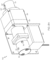
- FIG. 8A and FIG. 8B are a perspective view and a cross-sectional view, respectively, of another example of a metering pump 100.
- Components and features similar to those for the metering pump 30 described above are identified with similar reference numbers.
- Primed reference numbers are used to indicate components in the metering pump 100 having similar functions to counterpart components having unprimed reference numbers in the metering pump 30 but which may otherwise have different shapes, sizes and/or features.
- the metering pump 100 includes a housing having two housing parts 58' and 58" for fabrication purposes.
- a guide boss 101 at the right end that includes a slot 69' in which an anti-rotation guide pin 68' extends into for achieving axial translation of a lead screw 112, as further described below.
- the lead screw 112 is aligned, in part, in an axial bore in the guide boss 101.
- the guide boss 101 is made of plastic.
- the illustrated metering pump 100 has an offset drive configuration. Instead of a stepper motor 60 and planetary gearbox 61 that are both axially in line with the housing 58 and various other components, the stepper motor 60' is arranged to the side of the pump housing 58' and is coupled through a belt and pulley system and other intervening components to drive the plunger 42.
- this offset configuration results in a wider pump footprint, the length of the metering pump 100 is shorter and therefore may be a desirable configuration for some applications. In one non-limiting numerical example, the length of the metering pump 100 is approximately five centimeters (two inches) shorter than the length of the metering pump 30 described above.
- the belt and pulley system includes a first pulley 102 secured to the shaft 104 of the stepper motor 60' and a second pulley 106 secured to a drive nut 108.
- Dashed lines 110 indicate the location of a pulley belt used to transfer mechanical power from the stepper motor 60' to the drive nut 108.
- the mechanical advantage is determined by a ratio of the engagement surfaces of the two pulleys 106 and 102. In one example, the ratio is 5:1.
- the engagement surfaces may be smooth.
- the engagement surfaces may be toothed and the belt 110 may have an inner surface configured to engage teeth on each pulley 102 and 106.
- the drive nut 108 is free to rotate inside the axial bore in the pump housing 58' and includes internal threads in a bore that engage the threaded outer surface of the lead screw 112.
- the anti-rotation guide pin 68' extends out from an opening in the lead screw 112 into the slot 69' in the guide boss 101 which is parallel to an axis of the axial bore in the housing 58 and an axial bore in the guide boss 101.
- An optical sensor 86' is used to determine a plunger axial position (e.g., an end of travel axial position) based on interruption of light through an optical path, similar to the sensor 86 described above with respect to metering pump 30.
- a pusher cap 114 is affixed to the end of the lead screw 112 which is made of steel. In this instance, axial compression is of lesser concern due to the metal construction, therefore the pusher cap 114 is a substantially smaller sized component that is press fit into the end of the lead screw 112.
- the pusher cap 114 is made of a harder steel than the lead screw 112.
- the pusher cap includes a convex surface to push against the back surface of the plunger 42.
- the radius of curvature of the convex surface is substantially equal to the distance between the midpoint 116 of the expanded portion of the lead screw 112 inside the axial bore of the guide boss 101 and the location to the left in the figure where the lead screw threads constrain the lead screw 112 in the drive nut 108.
- the radius of curvature is greater than that for the convex surface 80 of the pusher cap 70 for the inline metering pump 30.
Landscapes
- Engineering & Computer Science (AREA)
- General Health & Medical Sciences (AREA)
- Immunology (AREA)
- Chemical & Material Sciences (AREA)
- Analytical Chemistry (AREA)
- Biochemistry (AREA)
- Physics & Mathematics (AREA)
- General Physics & Mathematics (AREA)
- Life Sciences & Earth Sciences (AREA)
- Pathology (AREA)
- Health & Medical Sciences (AREA)
- Mechanical Engineering (AREA)
- General Engineering & Computer Science (AREA)
- Reciprocating Pumps (AREA)
- Details Of Reciprocating Pumps (AREA)
Description
- This application claims the benefit of the earlier filing date of
U.S. Provisional Patent Application Serial No. 63/000,037, filed March 26, 2020 - The invention relates generally to pumps used for sample metering in liquid chromatography systems. More particularly, the invention relates to a pump having a modular design and other features to enable high-pressure metering and improve serviceability.
- High performance liquid chromatography (HPLC) systems and ultra-high performance liquid chromatography (UHPLC) systems often employ a sample metering pump to acquire small volumes of sample for injection into the system flow. Syringe drives maybe used but in some instances bubbles in the syringe can be difficult to purge during the system priming process. In addition, some applications can require a sample volume precision that cannot be met by conventional metering pumps.
- Servicing and maintenance of metering pumps typically presents a challenge. For example, the plunger and seals in the pump head may require replacement. Disassembly of the metering pump to access these components can result in a difficult task of properly installing and aligning the replacement components. Moreover, the time required to complete servicing or preventative maintenance can be problematic, requiring long system downtime or the need for a replacement metering pump.
-
WO 2005/000378 discloses a coupling system for an infusion pump.US 3880138 discloses a method for injecting contrast media into the vascular system. - In one aspect, a metering pump includes a pump housing, a drive nut, an anti-rotation guide pin, a lead screw and a pusher element. The pump housing has an axial bore and a slot parallel to an axis of the axial bore. The drive nut has a bore with internal threads and an opening. The drive nut disposed in the axial bore of the pump housing. The anti-rotation guide pin is at least partially disposed in the opening of the drive nut and extends into the slot of the pump housing. The lead screw has a threaded outer surface in engagement with the threaded bore of the drive nut. The pusher element is secured to the drive nut and has a convex surface. A rotation of the lead screw imparts an axial translation to the drive nut pusher element and plunger.
- The metering pump may include a stepper motor in mechanical communication with the lead screw. The metering pump may include a gearbox mechanically coupled to the lead screw and to the stepper motor.
- The metering pump includes a plunger having an end in contact with the convex surface of the pusher element. The plunger may include a plunger rod and a plunger hub, wherein an end of the plunger hub is in contact with the convex surface of the pusher element. The metering pump may include a guide washer affixed to the plunger hub. The guide washer may be formed of a polymer. The metering pump may include a pod head. The pod head includes a pump head and a cartridge housing. The pump head has a pump chamber to receive an end of the plunger rod and the cartridge housing is disposed between the pump head and the pump housing. The cartridge housing may have an axial cavity with a spring disposed therein. The spring is configured to apply an axial force to the plunger.
- The convex surface of the pusher element may have a radius of curvature equal to a distance between the convex surface and an axial point midway along a length of an outer surface of the drive nut adjacent to a surface of the axial bore.
- The metering pump may include a sensor fixed to an external surface of the housing along the slot. The sensor is configured to sense a presence of the anti-rotation guide pin at a fixed location along the slot. The sensor may be an optical sensor having an optical emitter and an optical detector configured to receive light emitted along an optical path from the optical emitter, wherein the optical detector generates a signal responsive to an interruption of the optical path by the anti-rotation guide pin.
- In another aspect, a metering pump includes a guide boss, a lead screw, a first pulley, a drive nut, an anti-rotation guide pin, a pusher cap and a plunger. The guide boss has an axial bore and a slot parallel to an axis of the axial bore. The lead screw is partially disposed in the axial bore and has a threaded surface and an opening. The drive nut is in mechanical communication with the first pulley. The anti-rotation guide pin is at least partially disposed in the opening of the lead screw and extends into the slot of the guide boss. The pusher cap is disposed at one end of the drive nut and has a convex surface. A rotation of the first pulley imparts a rotation to the drive nut and an axial translation to the lead screw and pusher cap.
- The metering pump may include a second pulley and a pulley belt coupling the first and second pulleys. The metering pump may further include a stepper motor having a shaft coupled to the second pulley, wherein a rotation of the shaft imparts a rotation to the first and second pulleys and the drive nut.
- The metering pump includes a plunger having an end in contact with the convex surface of the pusher cap. The plunger may include a plunger rod and a plunger hub, wherein an end of the plunger hub is in contact with the convex surface of the pusher cap. The metering pump may include a guide washer affixed to the plunger hub and the guide washer may be formed of a polymer. The metering pump may further include a pod head. The pod head includes a pump head having a pump chamber to receive an end of the plunger rod and a cartridge housing disposed between the pump head and the pump housing. The cartridge housing may have an axial cavity with a spring disposed therein, wherein the spring is configured to apply an axial force to the plunger.
- The convex surface of the pusher cap may have a radius of curvature equal to a distance between the convex surface and an axial point midway along a length of an expanded portion of the lead screw in the axial bore of the guide boss.
- The metering pump may include a sensor fixed to an external surface of the guide boss along the slot. The sensor is configured to sense a presence of the anti-rotation guide pin at a fixed location along the slot. The sensor may be an optical sensor having an optical emitter and an optical detector configured to receive light emitted along an optical path from the optical emitter, wherein the optical detector generates a signal responsive to an interruption of the optical path by the anti-rotation guide pin.
- The above and further advantages of this invention may be better understood by referring to the following description in conjunction with the accompanying drawings, in which like reference numerals indicate like elements and features in the various figures. For clarity, not every element may be labeled in every figure. The drawings are not necessarily to scale, emphasis instead being placed upon illustrating the principles of the technology.
-
FIG. 1 is a block diagram of a liquid chromatography system that may include one of the examples of a sample metering pump described herein. -
FIGS. 2A ,2B and2C are a top perspective view, a bottom perspective view and a cross-sectional view, respectively, of an example of a sample metering pump. -
FIG. 3 shows a drive nut, pusher cap and anti-rotation guide pin for the sample metering pump ofFIGS. 2A to 2C . -
FIG. 4 is a cross-sectional view of an embodiment of a head pod for the sample metering pump ofFIGS. 2A to 2C and shows the pump head, seal wash housing and cartridge housing. -
FIG. 5 is a cross-sectional illustration of an embodiment of a drive assembly that may be used as an alternative to the drive assembly ofFIGS. 2A to 2C . -
FIG. 6 is an alternative embodiment to the pump head shown inFIG. 4 . -
FIG. 7 is another alternative embodiment to the pump head shown inFIG. 4 . -
FIGS. 8A and8B are a perspective view and a cross-sectional view, respectively, of another example of a metering pump. - As used herein, a mobile phase is a solvent or mixture of solvents used to carry a sample and to pass through the stationary phase of a liquid chromatography system. The mobile phase may be a gradient mobile phase in which the composition of the mobile phase changes with time. The mobile phase may be referred to herein as the system flow which typically flows from the source of the mobile phase to at least the detector of the liquid chromatography system. A "sample" refers to a sample solution that contains the sample components to be injected into the system flow upstream from a chromatographic column. The sample is typically made available in a sample reservoir or sample container in the sample manager of the liquid chromatography system. The sample solution may include a sample diluent.
- In brief overview, the examples described below are directed to sample metering pumps that may be used to meter precise volumes of liquid for injection in a liquid chromatography system. In some implementations, the sample metering pump is able to withstand the full system pressure (e.g., up to 125 MPa (18,000 psi)) and may, in some instances, be able to pre-compress the aspirated sample up to full system pressure before injecting. Other advantages over conventional metering pumps include improved injector precision and linearity, improved reliability and aspiration accuracy and, in some implementations, a greater sample volume range. In addition, preventive maintenance may be unnecessary. For example, sample metering pumps generally employ substantially fewer pump strokes over time when compared to pumps used to provide a continuous high-pressure solvent flow for the mobile phase of the chromatography system.
- In some implementations, a modular configuration of the metering pump provides for a pod section ("head pod") and a drive section ("drive assembly") that may be separated from each other. This modular configuration results in easier serviceability. For example, replacement of the fluidic seals and/or plunger can be performed without disassembly of the assembly. Alternatively, a head pod may be replaced with another head pod so that the metering pump can be operable with little down time and so that the removed head pod can be serviced separately. The replacement head pod may be factory tested to eliminate any time that might otherwise be necessary to test a refurbished original head pod and to modify the original head pod based on those test results. Replacement of the head pod permits a quick reconfiguration of a sample manager to accommodate different operating conditions. For example, the replacement head pod may have a different plunger, seal, and pump chamber size to allow for operation at a different pressure range and acquisition of sample at different volumes with different volumetric precision.
- The present teaching will now be described in more detail with reference to examples shown in the accompanying drawings. While the present teaching is described in conjunction with various examples, it is not intended that the present teaching be limited to such examples. On the contrary, the present teaching encompasses various alternatives, modifications and equivalents, as will be appreciated by those of skill in the art. Those of ordinary skill having access to the teaching herein will recognize additional implementations, modifications and examples, as well as other fields of use, which are within the scope of the present disclosure.
- Reference in the specification to an "example" or "implementation" means that a particular feature, structure or characteristic described in connection with the example or implementation is included in at least one example or implementation of the teaching. References to a particular example or implementation within the specification do not necessarily all refer to the same example or implementation.
-
FIG. 1 is a block diagram of aliquid chromatography system 10 that can be modified to practice embodiments of the method of the invention. Thesystem 10 includes a system processor 12 (e.g., microprocessor and controller) in communication with auser interface device 14 for receiving input parameters and displaying system information to an operator. Thesystem processor 12 communicates with asolvent manager 16 which provides one or more solvents for a mobile phase. For example, thesolvent manager 16 may provide a gradient mobile phase. A sample provided by asample manager 20 is injected into the mobile phase upstream from achromatographic column 22 by aninjection valve 24. Thesample manager 20 can include a source of sample such as a sample reservoir, vial or other container that holds a volume of the sample. Thesample manager 20 may include a sample metering device used to aspirate an accurate volume of sample into a sample needle from the sample source. In some instances, thesample manager 20 provides a diluted sample that includes the sample and a diluent. Thechromatographic column 22 is coupled to adetector 26 which provides a signal to thesystem processor 12. The signal is responsive to various components detected in the eluent from thecolumn 22. After passing through thedetector 26, the system flow exits to a waste port; however, when used for fraction collection, a diverter valve is included to redirect the system flow to one or more collection vessels. - The sample metering device often provides limitations on the volume and volume accuracy of the sample injected into the system. In some instances, the fluidic network in communication with the metering device is adversely affected by bubbles, such as during the priming process when bubbles may not be sufficiently purged from the system. Moreover, serviceability is sometimes a problem as conventional metering pumps may not provide easy access to internal components. In addition, the ability to dispense the chromatographic sample at full system pressure may not be possible.
-
FIGS. 2A ,2B and2C are a top perspective view, a bottom perspective view and a cross-sectional view, respectively, of one example of asample metering pump 30. Thepump 30 includes a head pod and a drive assembly. The head pod includes apump head 36, acartridge housing 38, aseal wash housing 40 and aplunger rod 42A andplunger hub 42B (collectively plunger 42). Theplunger hub 42B includes a ceramic insert. In some embodiments, thepump head 36,cartridge housing 38 and seal washhousing 40 are made of steel and theplunger rod 42A is made of sapphire or zirconia. - The
pump head 36 includes apump chamber 44 to receive the plunger 42, apump inlet 46 and apump outlet 48. The seal washhousing 40 includes a first gland at one end having a firstfluidic seal 50 and a second gland at an opposite end having asecond fluidic seal 52. One or bothfluidic seals second seal 52 is a high-pressure seal which seals at the operating pressure of the liquid chromatography system. The seal washhousing 40 also includes aninlet 54 configured to receive a fitting to couple to tubing that conducts a wash solvent. The wash solvent is used to clean the outer surface of the plunger 42 on the lower pressure side of the high-pressure seal 52. The seal washhousing 40 further includes anoutlet 56 configured to receive a fitting to couple to tubing to conduct the wash solvent away from themetering pump 30. - The drive assembly includes a
pump housing 58,stepper motor 60,planetary gearbox 61,lead screw 62, angular contact bearing 64 and drivenut 66. The angular contact bearing 64 is held in place and biased against an inner surface of thehousing 58 by a bearingretainer ring 65. Thegearbox 61 enables a greater torque to be applied with a corresponding reduction in rotation rate. In one implementation, the gearbox provides a gearset reduction of 5:1. Thelead screw 62 may have a spline feature formed at the back (right) end to interface with thegearset 61. Thegearbox 61 rests against an O-ring 63 positioned on a reduced diameter portion of thelead screw 62 near the spline feature. Thelead screw 62 is fixed at the spline feature to theplanetary gearbox 61. - Referring also to
FIG. 3 , thedrive nut 66 has an outer diameter D that is less that the bore diameter of the adjacent region of thepump housing 58. In one implementation, thedrive nut 66 is formed of a plastic or other polymer.Internal threads 67 in a bore of thedrive nut 66 engage the threaded outer surface of thelead screw 62. Apusher cap 70 used to apply axial force to the plunger 42 is secured at a narrowed end of thedrive nut 66 that is opposite to thelead screw 62. Thepusher cap 70 includes an opening to pass ananti-rotation guide pin 68 and aconvex surface 80, described in more detail below, which is in contact with theplunger hub 42B. Preferably, the assembly comprising thedrive nut 66 andpusher cap 70 is sufficiently stiff so as to minimize deformation during the application of axial force. In some embodiments, thepusher cap 70 is formed of steel or another stiff material and has an axial length chosen to be as large as practical to limit compression during axial load. - The
pusher cap 70 has aclearance hole 71 in its side with a diameter that is greater than a diameter of theguide pin 68 and the diameter of theguide pin 68 is slightly greater than a diameter of a though hole in the narrowed end of thedrive nut 66. During assembly, thepusher cap 70 is attached to the narrowed end of thedrive nut 66 and then theguide pin 68 is press fit into thedrive nut 66 through the clearance hole in thepusher cap 70 so that the through hole is occupied by a portion of theguide pin 68 with the remainder extending outward from one end. The extended portion of theguide pin 68 is constrained to move within aslot 69 formed in the bottom of the pump housing 58 (seeFIG. 2B ). Theslot 69 is parallel to an axis of the housing axial bore. The width of theslot 69 is sized to be slightly greater than the outer diameter of thepin 68 and the length of theslot 69 is parallel to the longitudinal axes of thelead screw 62 and drivenut 66. The constraint imposed on theguide pin 68 by theslot 69 prevents rotation of thedrive nut 66 during pump operation and consequently allows only motion in a direction parallel to the length of theslot 69. Themotor 60 andplanetary gearbox 61 are configured to impart a rotation to thelead screw 62 which in turn imparts a linear (axial) translation to thedrive nut 66 andpusher cap 70 parallel to the length of theslot 69. The length of theslot 69 is sufficient to enable the full range of motion of the plunger 42 during pump operation. - Operation of the
stepper motor 60 in one rotational direction results in a translation of thedrive nut 66 such that thepusher cap 70 imparts a force to the plunger 42 directed along the axis of thepump housing 58. The force moves the plunger 42 further into thepump chamber 44. Rotation of thestepper motor 60 in an opposite direction results in a reverse translation such that the plunger 42 is drawn backwards, i.e., in a direction out from thepump chamber 44. The force used to draw the plunger 42 backwards is applied by aspring 72 disposed in a cavity in thecartridge housing 38 as shown inFIG. 4 . Thespring 72 is installed at a preload to ensure there is always sufficient spring force to overcome friction in the system, including friction between the outer diameter of theplunger rod 42A and the inner diameter of theseals pusher cap 70 and the back of theplunger hub 42B when the plunger 42 is drawn backwards. Thecartridge housing 38 further includes anassembly guide ring 85 pressed into an opening at the left side where the plunger 42 extends from the cavity through thefirst fluidic seal 50 into thewash housing 40. Theassembly guide ring 85 prevents scratching of the plunger 42 during assembly when proper alignment of the plunger 42 may be difficult due to the compression of thespring 72 and the obstructed view of the assembler. During operation, the plunger 42 is guided by the high-pressure fluidic seal 52 and apolymer guide washer 43 which is pressed onto theplunger hub 42B. - One end of the
spring 72 engages theplunger hub 42B and is maintained inside the cavity under compression by aninternal retention ring 84. Thespring 72 maintains contact of theplunger hub 42B with thecontact surface 80 of thepusher cap 70 without requiring it to be securely attached to thepusher cap 70. Advantageously, this lack of a secure attachment enables the head pod to be detached from the drive assembly without the plunger 42 coming loose. The head pod may be separated from the drive assembly to perform maintenance or otherwise service the head pod. For example, replacement of the low-pressure seal 50 and/or high-pressure seal 52 can be performed on the removed head pod. - The separability of the head pod and drive assembly provides advantages over solvent manager pump actuators which may include a drive mechanism that includes a ball detent and a plunger having a ball neck to engage the ball detent. In the conventional configurations, the physical connection between the ball detent and the ball neck prevents their separation. Moreover, if the drive assembly is laterally misaligned with respect to the head pod in the conventional metering pump, the plunger is laterally translated from its ideal position and there may be a small angular misalignment of the plunger with respect to the pump longitudinal axis. This misalignment can cause a degradation in operation.
- Unlike some chromatographic system pumps such as mobile phase solvent pumps, the
metering pump 30 does not operate with a high number of cycles. For example, only a single cycle, or a small number of cycles, depending on sample manager configuration, may be used to acquire sample for injection. The volume of liquid moved by the plunger 42 and the load on themetering pump 30 are dependent on the size of the plunger 42. For example, if operating themetering pump 30 at 70 MPa (10,000 psi) with a 0.30 cm (0.125 in.) diameter plunger and a 100 µL pump stroke volume, a force of approximately 140 pounds may be used. This force is sufficient to overcome pump friction and the force applied by thespring 72. However, if high precision for small sample volumes is desired, it may be preferable to operate themetering pump 30 using the same drive assembly with a head pod that has a smaller plunger and smaller pump chamber. In addition, smaller plunger sizes also allow a decrease in the drive force required to move fluid at higher pressures and therefore decrease the torque requirements for themotor 60. By way of an example, the plunger 42 may have a 2.0 mm (0.08 in.) diameter, the pump stroke volume may be 40 µ1. and themetering pump 30 may be operated at pressures up to or exceeding 125 MPa (18,000 psi). The replacement head pod may provide better precision because the displacement volume per motor step is smaller. -
FIG. 3 is an expanded view of thepusher cap 70 showing aconvex surface 80 that engages the flat surface at the back end of theplunger hub 42B. Thedrive nut 66 is constrained to axial movement in the axial bore of thehousing 58. Due to the clearance between the outer diameter of thedrive nut 66 and the diameter of the axial bore, there is a potential for thedrive nut 66 to have a small tilt with respect to the housing longitudinal axis. Consequently, the tilt of thedrive nut 66 may rotate about apoint 82 that is approximately midway along a length L of its outer surface. If the radius of curvature R of thesurface 80 equals the distance between theconvex surface 80 and themidway point 82, any tilt aboutpoint 82 will not change the lateral position of the point of contact on the flat surface of the plunger 42. In addition, if thepusher cap 70 is misaligned laterally, the direction of the force applied by thepusher cap 70 on the plunger 42 remains unchanged. - Referring again to
FIGS. 2B and2C , anoptical sensor 86 is attached to the bottom surface of thehousing 58 near one end of theslot 69 used to constrain theanti-rotation guide pin 68. The optical sensor includes twoside extensions guide pin 68. As illustrated, theguide pin 68 is near an end of theslot 69 away from theoptical sensor 86. As thedrive nut 66 andpusher cap 70 move the plunger 42 into thepump chamber 44, theguide pin 68 moves within theslot 69 toward theoptical sensor 86. As the plunger 42 reaches its maximum inward position inside thepump chamber 44, the edge of theguide pin 68 interrupts the optical path between the optical emitter and optical detector. The decrease in the light power incident on the optical detector causes a signal change associated with a reference position for the plunger 42. Other plunger positions can then be determined based on the number of stepper motor steps from the reference position. For example, the reference position may be the end of travel position for the plunger 42. In alternative embodiments, theoptical sensor 86 may be at a different position such as at the opposite end of theslot 69. In other embodiments, a different type of sensor may be used to determine the position of the plunger 42. For example, an encoder that defines a reference position against a physical stop can be used as an alternative means to control position. -
FIG. 5 is a cross-sectional illustration of an embodiment of a drive assembly that may be used in place of the drive assembly shown inFIGS. 2A to 2C . Instead of thepolymer drive nut 66 moving in the axial bore of thehousing 58, the illustrated embodiment makes use of additional components inside the axial bore. More specifically, instead of using apusher cap 70 as a pusher element (i.e., an element used to urge the plunger 42 into the pump chamber 44), apusher jacket 74 is used. Thepusher jacket 74 is a substantially cylindrical component having a convex contact surface 80' at one end. Thepusher jacket 74 is press fit onto thedrive nut 66 through the other jacket end. Thepusher jacket 74 circumferentially encloses thedrive nut 66. Preferably, thepusher jacket 74 is made of a hardened stainless steel. Abronze bushing 76 is secured in the axial bore of thepump housing 58. During pump operation, thepusher jacket 74 andenclosed drive nut 66 move axially through thebronze bushing 76. Ananti-rotation guide pin 68 extends from thedrive nut 66 through thepusher jacket 74 and through ananti-rotation bearing 78 in a side wall of thebronze bushing 76. - The use of bronze and stainless steel allows for tighter dimensional manufacturing tolerances and therefore the gap between the
pusher jacket 74 andbronze bushing 76 can be less than the gap between thepusher cap 70 andhousing 58 in the embodiment shown inFIGS. 2A to 2C . Preferably, thepusher jacket 74 has a diamond-like carbon (DLC) coating to improve hardness. Grease or another lubricant may be applied to a portion of the outer surface of thepusher jacket 74. One or morecircumferential grooves 79 may be formed in the inner surface of thebronze bushing 76 to accept and hold excess lubricant. - In various embodiments described above with respect to
FIG. 4 , theguide washer 43 slides along the inner bore of thecartridge housing 38 during motion of the plunger 42. There is a small clearance between the bore inner diameter and the outer surface of the plunger 42. Similarly, there is a small clearance between the inner diameter of abackup ring 45 that is adjacent to thehigh pressure seal 52. Thebackup ring 45 may be made, for example, from a hard plastic. The combination of theguide washer 43 and thebacking plate 45 establish the alignment of the plunger 42 and prevent any significant tilting with respect to the axis of linear motion. -
FIG. 6 shows an alternative embodiment to the pump head shown inFIG. 4 . Although the plunger 42 is supported at one location by thebackup ring 45, the guide washer 43' does not provide a means for aligning plunger 42. Instead, aguide bushing 47 is pressed into thecartridge housing 38. In some embodiments, theguide bushing 47 is made of a plastic and in other embodiments it is made of a ceramic material such as zirconia. Like the opening in thebackup ring 45, the diameter of the opening in theguide bushing 47 is closely matched to the diameter of the plunger 42 and the clearance may be, for example, on the order of 0.001 in. Thus, thebackup ring 45 and guidebushing 47 establish the alignment of the plunger 42 and prevent any significant variation in the angular orientation of the plunger 42 with respect to the axis of plunger motion. - In the illustrated embodiment, the manufacturing methods allow the surfaces that rub against each other to be formed as highly smooth surfaces. For example, the plunger 42 may be made of sapphire and have a smooth surface and the
guide bushing 47 may be made of zirconia. Thus, the wear and friction characteristics due to these hard surfaces may be significantly improved. -
FIG. 7 shows another alternative embodiment to the pump head shown inFIG. 4 . In this illustrated embodiment, the cartridge housing 38' is made of aluminum coated with polytetrafluoroethylene (PTFE). Aretention plate 49 made of stainless steel is used to hold thelow pressure seal 50 in place in the seal washhousing 40. Theseal 50 may be wet by solvent therefore theretention plate 49 may be in contact with the solvent. The coating provides reduced friction with respect to the internal moving parts and provides an additional benefit of protecting the cartridge housing 38' against contact with solvents. The stainlesssteel retention plate 49 prevents a strong solvent that might otherwise be capable of degrading the coating and reaching the aluminum material from having the opportunity to reach the coated surface of the cartridge housing 38'. - The PTFE coating is applied generally to all surfaces of the cartridge housing 38'. In one example, the aluminum cartridge housing 38' is anodized to create an aluminum oxide layer before applying the PTFE to the housing surface. Advantageously, the bore of the cartridge housing 38' is coated with PTFE and therefore, instead of sliding on a stainless steel surface, the
polymer guide washer 43 slides along the low friction surface of the hard-coated PTFE aluminum surface. -
FIG. 8A andFIG. 8B are a perspective view and a cross-sectional view, respectively, of another example of ametering pump 100. Components and features similar to those for themetering pump 30 described above are identified with similar reference numbers. Primed reference numbers are used to indicate components in themetering pump 100 having similar functions to counterpart components having unprimed reference numbers in themetering pump 30 but which may otherwise have different shapes, sizes and/or features. Unlike themetering pump 30 described above, themetering pump 100 includes a housing having twohousing parts 58' and 58" for fabrication purposes. In addition, there is aguide boss 101 at the right end that includes a slot 69' in which an anti-rotation guide pin 68' extends into for achieving axial translation of alead screw 112, as further described below. Thelead screw 112 is aligned, in part, in an axial bore in theguide boss 101. In one embodiment, theguide boss 101 is made of plastic. - Unlike the
metering pump 30 which has an inline drive configuration, the illustratedmetering pump 100 has an offset drive configuration. Instead of astepper motor 60 andplanetary gearbox 61 that are both axially in line with thehousing 58 and various other components, the stepper motor 60' is arranged to the side of the pump housing 58' and is coupled through a belt and pulley system and other intervening components to drive the plunger 42. Although this offset configuration results in a wider pump footprint, the length of themetering pump 100 is shorter and therefore may be a desirable configuration for some applications. In one non-limiting numerical example, the length of themetering pump 100 is approximately five centimeters (two inches) shorter than the length of themetering pump 30 described above. - The belt and pulley system includes a
first pulley 102 secured to theshaft 104 of the stepper motor 60' and asecond pulley 106 secured to adrive nut 108. Dashedlines 110 indicate the location of a pulley belt used to transfer mechanical power from the stepper motor 60' to thedrive nut 108. The mechanical advantage is determined by a ratio of the engagement surfaces of the twopulleys belt 110 may have an inner surface configured to engage teeth on eachpulley - The
drive nut 108 is free to rotate inside the axial bore in the pump housing 58' and includes internal threads in a bore that engage the threaded outer surface of thelead screw 112. The anti-rotation guide pin 68' extends out from an opening in thelead screw 112 into the slot 69' in theguide boss 101 which is parallel to an axis of the axial bore in thehousing 58 and an axial bore in theguide boss 101. Thus, as the rotation of thestepper motor shaft 104 is transferred by the belt and pulley system to cause a rotation of thedrive nut 108, thelead screw 112 translates linearly along the bore axis and applies a linear force to move the plunger 42 into thepump chamber 44. Thespring 72 in thecartridge housing 38 provides force to withdraw (push) the plunger 42 out from thepump chamber 44 when thestepper motor shaft 104 rotates in the opposite direction and causes thelead screw 112 to translate in the opposite direction. - An optical sensor 86' is used to determine a plunger axial position (e.g., an end of travel axial position) based on interruption of light through an optical path, similar to the
sensor 86 described above with respect tometering pump 30. - A
pusher cap 114 is affixed to the end of thelead screw 112 which is made of steel. In this instance, axial compression is of lesser concern due to the metal construction, therefore thepusher cap 114 is a substantially smaller sized component that is press fit into the end of thelead screw 112. Preferably, thepusher cap 114 is made of a harder steel than thelead screw 112. The pusher cap includes a convex surface to push against the back surface of the plunger 42. In one embodiment, the radius of curvature of the convex surface is substantially equal to the distance between themidpoint 116 of the expanded portion of thelead screw 112 inside the axial bore of theguide boss 101 and the location to the left in the figure where the lead screw threads constrain thelead screw 112 in thedrive nut 108. Thus, the radius of curvature is greater than that for theconvex surface 80 of thepusher cap 70 for theinline metering pump 30. - While the technology has been shown and described with reference to specific embodiments, it should be understood by those skilled in the art that various changes in form and detail may be made therein without departing from the scope of the claims.
Claims (15)
- A metering pump (30), comprising:a pump housing (58) having an axial bore and a slot (69) parallel to an axis of the axial bore;a drive nut (66) having a bore with internal threads (67) and having an opening, the drive nut (66) disposed in the axial bore of the pump housing (58);an anti-rotation guide pin (68) at least partially disposed in the opening of the drive nut (66) and extending into the slot (69) of the pump housing (58);a lead screw (62) having a threaded outer surface in engagement with the threaded bore of the drive nut (66); anda pusher element secured to the drive nut (66) and having a convex surface (80); anda plunger (42) having an end in contact with the convex surface (80) of the pusher element,wherein a rotation of the lead screw (62) imparts an axial translation to the drive nut (66), pusher element and plunger (42).
- The metering pump (30) of claim 1 further comprising a stepper motor (60) in mechanical communication with the lead screw (62).
- The metering pump (30) of claim 1 wherein the plunger (42) comprises a plunger rod (42A) and a plunger hub (42B), wherein an end of the plunger hub (42B) is in contact with the convex surface (80) of the pusher element.
- The metering pump (30) of claim 3 further comprising a pod head, the pod head comprising:a pump head (36) having a pump chamber (44) to receive an end of the plunger rod (42A); anda cartridge housing (38) disposed between the pump head (36) and the pump housing (58).
- The metering pump (30) of claim 4 wherein the cartridge housing (38) has an axial cavity with a spring (72) disposed therein, the spring (72) configured to apply an axial force to the plunger (42).
- The metering pump (30) of claim 3 further comprising a guide washer (43) affixed to the plunger hub (42B).
- The metering pump (30) of claim 1, wherein the convex surface (80) has a radius of curvature equal to a distance between the convex surface (80) and an axial point midway along a length of an outer surface of the drive nut (66) adjacent to a surface of the axial bore.
- The metering pump (30) of claim 1 further comprising a sensor fixed to an external surface of the housing (58) along the slot (69), the sensor configured to sense a presence of the anti-rotation guide pin (68) at a fixed location along the slot (69).
- The metering pump (30) of claim 8 wherein the sensor is an optical sensor (86) having an optical emitter and an optical detector configured to receive light emitted along an optical path from the optical emitter and wherein the optical detector generates a signal responsive to an interruption of the optical path by the anti-rotation guide pin (68).
- A metering pump (100), comprising:a guide boss (101) having an axial bore and a slot (69') parallel to an axis of the axial bore;a lead screw (112) partially disposed in the axial bore and having a threaded surface and an opening;a first pulley (102);a drive nut (108) in mechanical communication with the first pulley (102);an anti-rotation guide pin (68') at least partially disposed in the opening of the lead screw (112) and extending into the slot (69') of the guide boss (101);a pusher cap (114) disposed at one end of the drive nut (108) and having a convex surface; anda plunger (42) having an end in contact with the convex surface of the pusher cap (114),wherein a rotation of the first pulley (102) imparts a rotation to the drive nut (108) and an axial translation to the lead screw (112) and pusher cap (114).
- The metering pump (100) of claim 10 wherein the plunger (42) comprises a plunger rod (42A) and a plunger hub (42B) and wherein an end of the plunger hub (42B) is in contact with the convex surface of the pusher cap (114).
- The metering pump (100) of claim 11 further comprising a pod head, the pod head comprising:a pump head (36) having a pump chamber (44) to receive an end of the plunger rod (42A); anda cartridge housing (38) disposed between the pump head (36) and a pump housing (58').
- The metering pump (100) of claim 12 wherein the cartridge housing (38) has an axial cavity with a spring (72) disposed therein, the spring (72) configured to apply an axial force to the plunger (42).
- The metering pump (100) of claim 11 further comprising a guide washer (43) affixed to the plunger hub (42B).
- The metering pump (100) of claim 10, wherein the convex surface has a radius of curvature equal to a distance between the convex surface and an axial point midway along a length of an expanded portion of the lead screw (112) in the axial bore of the guide boss (101).
Applications Claiming Priority (2)
| Application Number | Priority Date | Filing Date | Title |
|---|---|---|---|
| US202063000037P | 2020-03-26 | 2020-03-26 | |
| PCT/US2021/024092 WO2021195338A1 (en) | 2020-03-26 | 2021-03-25 | Metering pump for liquid chromatography |
Publications (2)
| Publication Number | Publication Date |
|---|---|
| EP4127469A1 EP4127469A1 (en) | 2023-02-08 |
| EP4127469B1 true EP4127469B1 (en) | 2024-08-28 |
Family
ID=75498097
Family Applications (1)
| Application Number | Title | Priority Date | Filing Date |
|---|---|---|---|
| EP21718780.6A Active EP4127469B1 (en) | 2020-03-26 | 2021-03-25 | Metering pump for liquid chromatography |
Country Status (4)
| Country | Link |
|---|---|
| US (1) | US11774415B2 (en) |
| EP (1) | EP4127469B1 (en) |
| CN (1) | CN115667713A (en) |
| WO (1) | WO2021195338A1 (en) |
Citations (1)
| Publication number | Priority date | Publication date | Assignee | Title |
|---|---|---|---|---|
| US3880138A (en) * | 1973-03-12 | 1975-04-29 | Lear Siegler Inc | Method for injecting contrast media into the vascular system |
Family Cites Families (37)
| Publication number | Priority date | Publication date | Assignee | Title |
|---|---|---|---|---|
| US2702547A (en) * | 1950-02-27 | 1955-02-22 | Antonina S Glass | Motor-driven medical injection apparatus and cartridges therefor |
| US3362339A (en) | 1965-10-01 | 1968-01-09 | Leeds & Northrup Co | Metering pump |
| USRE31586E (en) | 1977-01-21 | 1984-05-15 | Altex Scientific, Inc. | Liquid chromatography pump |
| US4389163A (en) | 1979-01-02 | 1983-06-21 | Altex Scientific, Inc. | Pressure booster system for fluids |
| EP0239622A1 (en) | 1985-10-02 | 1987-10-07 | Beckman Instruments, Inc. | Method and apparatus for sequencing small samples of peptides and proteins |
| US4859605A (en) | 1986-12-16 | 1989-08-22 | Ciba-Geigy Corporation | Process for preparation of samples for analysis |
| EP0259259A3 (en) | 1986-08-28 | 1989-05-17 | Ciba-Geigy Ag | System for preparation of samples for analysis |
| EP0259257A3 (en) | 1986-08-28 | 1989-02-15 | Ciba-Geigy Ag | Process for preparation of samples for analysis |
| US4980130A (en) | 1986-12-16 | 1990-12-25 | Ciba-Geigy Corporation | System for preparation of samples for analysis |
| US4894345A (en) | 1986-12-16 | 1990-01-16 | Ciba-Geigy Corporation | Process for preparation of samples for analysis |
| US4900683A (en) | 1986-12-16 | 1990-02-13 | Ciba-Geigy Corporation | Process for preparation of samples for analysis |
| US5635070A (en) * | 1990-07-13 | 1997-06-03 | Isco, Inc. | Apparatus and method for supercritical fluid extraction |
| US5322511A (en) * | 1992-04-21 | 1994-06-21 | Sterling Winthrop Inc. | Portable hand-held power injector |
| US5656034A (en) | 1995-03-31 | 1997-08-12 | Perkin Elmer Corp | High-pressure micro-volume syringe pump |
| US7225079B2 (en) | 1998-08-04 | 2007-05-29 | Transgenomic, Inc. | System and method for automated matched ion polynucleotide chromatography |
| WO2001046687A2 (en) | 1999-12-22 | 2001-06-28 | Transgenomic, Inc. | System and method for automated matched ion polynucleotide chromatography |
| US20050020980A1 (en) * | 2003-06-09 | 2005-01-27 | Yoshio Inoue | Coupling system for an infusion pump |
| WO2005050190A2 (en) | 2003-11-05 | 2005-06-02 | Agilent Technologies, Inc. | Chromatography system |
| US7329485B2 (en) | 2005-10-12 | 2008-02-12 | The Board Of Regents Of The University Of Oklahoma | Methods for detecting compounds that interfere with protein aggregation utilizing an in vitro fluorescence-based assay |
| US8215922B2 (en) | 2008-06-24 | 2012-07-10 | Aurora Sfc Systems, Inc. | Compressible fluid pumping system for dynamically compensating compressible fluids over large pressure ranges |
| US9163618B2 (en) | 2008-06-24 | 2015-10-20 | Agilent Technologies, Inc. | Automated conversion between SFC and HPLC |
| US8776621B2 (en) | 2009-03-06 | 2014-07-15 | Dionex Corporation | Fluid sample delivery system and method |
| US9533093B2 (en) | 2010-06-05 | 2017-01-03 | Amrita Vishwa Vidyapeetham | Cartridge connection method for precise delivery of liquid |
| US8915879B2 (en) | 2010-09-24 | 2014-12-23 | Perqflo, Llc | Infusion pumps |
| US10054569B2 (en) | 2010-10-29 | 2018-08-21 | Thermo Finnigan Llc | Method and system for liquid chromatography fluidic monitoring |
| GB2487942A (en) * | 2011-02-09 | 2012-08-15 | Agilent Technologies Inc | A method for metering two or more liquids in controlled proportions |
| WO2013136802A1 (en) * | 2012-03-16 | 2013-09-19 | テルモ株式会社 | Drug administration device |
| EP2677313A1 (en) | 2012-06-22 | 2013-12-25 | Agilent Technologies, Inc. | Compressible fluid pumping system for dynamically compensating compressible fluids over large pressure ranges |
| US10591446B2 (en) * | 2014-03-31 | 2020-03-17 | Agilent Technologies, Inc. | Sealing moving with piston in a high-pressure pump |
| CN203783840U (en) * | 2014-04-24 | 2014-08-20 | 山东海燕医用材料制造有限公司 | Precision metering liquid charging pump with ceramic plunger |
| CN105065223A (en) * | 2015-08-05 | 2015-11-18 | 浙江福立分析仪器有限公司 | High-pressure plunger infusion pump and aligning method thereof |
| CN205277735U (en) * | 2016-01-08 | 2016-06-01 | 威海世椿自动化设备有限公司 | Measuring pump drive arrangement |
| JP2017127502A (en) * | 2016-01-21 | 2017-07-27 | 大研医器株式会社 | Syringe and syringe pump device provided with the same |
| US10760557B1 (en) | 2016-05-06 | 2020-09-01 | Pumptec, Inc. | High efficiency, high pressure pump suitable for remote installations and solar power sources |
| CN110753842B (en) | 2017-06-19 | 2022-12-09 | 沃特世科技公司 | In-Line Dilution of an LC System Using a Sample Metering Pump |
| EP3617701B1 (en) | 2018-08-27 | 2024-10-23 | F. Hoffmann-La Roche AG | Sample injector with sample loop and buffer loop |
| US11242871B2 (en) * | 2018-09-18 | 2022-02-08 | Waters Technologies Corporation | Continuously variable output liquid chromatography pump drive |
-
2021
- 2021-03-25 CN CN202180037974.5A patent/CN115667713A/en active Pending
- 2021-03-25 US US17/212,329 patent/US11774415B2/en active Active
- 2021-03-25 WO PCT/US2021/024092 patent/WO2021195338A1/en not_active Ceased
- 2021-03-25 EP EP21718780.6A patent/EP4127469B1/en active Active
Patent Citations (1)
| Publication number | Priority date | Publication date | Assignee | Title |
|---|---|---|---|---|
| US3880138A (en) * | 1973-03-12 | 1975-04-29 | Lear Siegler Inc | Method for injecting contrast media into the vascular system |
Also Published As
| Publication number | Publication date |
|---|---|
| US20210302397A1 (en) | 2021-09-30 |
| US11774415B2 (en) | 2023-10-03 |
| WO2021195338A1 (en) | 2021-09-30 |
| EP4127469A1 (en) | 2023-02-08 |
| CN115667713A (en) | 2023-01-31 |
Similar Documents
| Publication | Publication Date | Title |
|---|---|---|
| EP0871875B1 (en) | High-pressure micro-volume syringe pump | |
| US8322374B2 (en) | Channel switching valve | |
| US4173437A (en) | Dual-piston reciprocating pump assembly | |
| US20190282284A1 (en) | Pump | |
| US7665480B2 (en) | Defined lead path for high pressure seal | |
| US10935153B2 (en) | Proportional flow control valve poppet with flow control needle | |
| US20170138913A1 (en) | Sealing moving with piston in a high-pressure pump | |
| US20240392777A1 (en) | Syringe pump | |
| US20100327577A1 (en) | Fitting connection | |
| EP3027942B1 (en) | Check valve having polymeric seat and poppet | |
| US20080166248A1 (en) | Coupling system for use with fluid displacement apparatus | |
| US11774415B2 (en) | Metering pump for liquid chromatography | |
| US4260342A (en) | Dual-piston reciprocating pump assembly | |
| US20140271264A1 (en) | Piston pump drive train anti-backlash | |
| JP2002202066A (en) | Liquid ejection device | |
| US7217105B2 (en) | Integrated pump and wash pump | |
| US7080975B2 (en) | Integrated pump and ceramic valve | |
| US6467655B1 (en) | Pump dispenser | |
| CN118257712A (en) | Infusion pump and liquid chromatograph | |
| US20100147758A1 (en) | Tension-force coupled high-pressure pumping | |
| CN117231492A (en) | Low-pressure chromatographic plunger pump | |
| JP2005016368A (en) | Liquid discharging device | |
| WO2005103491A2 (en) | Air displacement apparatus for use with a fluid transfer device |
Legal Events
| Date | Code | Title | Description |
|---|---|---|---|
| STAA | Information on the status of an ep patent application or granted ep patent |
Free format text: STATUS: UNKNOWN |
|
| STAA | Information on the status of an ep patent application or granted ep patent |
Free format text: STATUS: THE INTERNATIONAL PUBLICATION HAS BEEN MADE |
|
| PUAI | Public reference made under article 153(3) epc to a published international application that has entered the european phase |
Free format text: ORIGINAL CODE: 0009012 |
|
| STAA | Information on the status of an ep patent application or granted ep patent |
Free format text: STATUS: REQUEST FOR EXAMINATION WAS MADE |
|
| 17P | Request for examination filed |
Effective date: 20220921 |
|
| AK | Designated contracting states |
Kind code of ref document: A1 Designated state(s): AL AT BE BG CH CY CZ DE DK EE ES FI FR GB GR HR HU IE IS IT LI LT LU LV MC MK MT NL NO PL PT RO RS SE SI SK SM TR |
|
| DAV | Request for validation of the european patent (deleted) | ||
| DAX | Request for extension of the european patent (deleted) | ||
| GRAP | Despatch of communication of intention to grant a patent |
Free format text: ORIGINAL CODE: EPIDOSNIGR1 |
|
| STAA | Information on the status of an ep patent application or granted ep patent |
Free format text: STATUS: GRANT OF PATENT IS INTENDED |
|
| INTG | Intention to grant announced |
Effective date: 20240322 |
|
| GRAS | Grant fee paid |
Free format text: ORIGINAL CODE: EPIDOSNIGR3 |
|
| GRAA | (expected) grant |
Free format text: ORIGINAL CODE: 0009210 |
|
| STAA | Information on the status of an ep patent application or granted ep patent |
Free format text: STATUS: THE PATENT HAS BEEN GRANTED |
|
| P01 | Opt-out of the competence of the unified patent court (upc) registered |
Free format text: CASE NUMBER: APP_39626/2024 Effective date: 20240703 |
|
| AK | Designated contracting states |
Kind code of ref document: B1 Designated state(s): AL AT BE BG CH CY CZ DE DK EE ES FI FR GB GR HR HU IE IS IT LI LT LU LV MC MK MT NL NO PL PT RO RS SE SI SK SM TR |
|
| REG | Reference to a national code |
Ref country code: CH Ref legal event code: EP |
|
| REG | Reference to a national code |
Ref country code: DE Ref legal event code: R096 Ref document number: 602021017923 Country of ref document: DE |
|
| REG | Reference to a national code |
Ref country code: IE Ref legal event code: FG4D |
|
| REG | Reference to a national code |
Ref country code: LT Ref legal event code: MG9D |
|
| PG25 | Lapsed in a contracting state [announced via postgrant information from national office to epo] |
Ref country code: NO Free format text: LAPSE BECAUSE OF FAILURE TO SUBMIT A TRANSLATION OF THE DESCRIPTION OR TO PAY THE FEE WITHIN THE PRESCRIBED TIME-LIMIT Effective date: 20241128 |
|
| REG | Reference to a national code |
Ref country code: AT Ref legal event code: MK05 Ref document number: 1718204 Country of ref document: AT Kind code of ref document: T Effective date: 20240828 |
|
| PG25 | Lapsed in a contracting state [announced via postgrant information from national office to epo] |
Ref country code: NL Free format text: LAPSE BECAUSE OF FAILURE TO SUBMIT A TRANSLATION OF THE DESCRIPTION OR TO PAY THE FEE WITHIN THE PRESCRIBED TIME-LIMIT Effective date: 20240828 Ref country code: PL Free format text: LAPSE BECAUSE OF FAILURE TO SUBMIT A TRANSLATION OF THE DESCRIPTION OR TO PAY THE FEE WITHIN THE PRESCRIBED TIME-LIMIT Effective date: 20240828 Ref country code: GR Free format text: LAPSE BECAUSE OF FAILURE TO SUBMIT A TRANSLATION OF THE DESCRIPTION OR TO PAY THE FEE WITHIN THE PRESCRIBED TIME-LIMIT Effective date: 20241129 Ref country code: FI Free format text: LAPSE BECAUSE OF FAILURE TO SUBMIT A TRANSLATION OF THE DESCRIPTION OR TO PAY THE FEE WITHIN THE PRESCRIBED TIME-LIMIT Effective date: 20240828 Ref country code: PT Free format text: LAPSE BECAUSE OF FAILURE TO SUBMIT A TRANSLATION OF THE DESCRIPTION OR TO PAY THE FEE WITHIN THE PRESCRIBED TIME-LIMIT Effective date: 20241230 |
|
| PG25 | Lapsed in a contracting state [announced via postgrant information from national office to epo] |
Ref country code: BG Free format text: LAPSE BECAUSE OF FAILURE TO SUBMIT A TRANSLATION OF THE DESCRIPTION OR TO PAY THE FEE WITHIN THE PRESCRIBED TIME-LIMIT Effective date: 20240828 |
|
| PG25 | Lapsed in a contracting state [announced via postgrant information from national office to epo] |
Ref country code: LV Free format text: LAPSE BECAUSE OF FAILURE TO SUBMIT A TRANSLATION OF THE DESCRIPTION OR TO PAY THE FEE WITHIN THE PRESCRIBED TIME-LIMIT Effective date: 20240828 |
|
| REG | Reference to a national code |
Ref country code: NL Ref legal event code: MP Effective date: 20240828 |
|
| PG25 | Lapsed in a contracting state [announced via postgrant information from national office to epo] |
Ref country code: IS Free format text: LAPSE BECAUSE OF FAILURE TO SUBMIT A TRANSLATION OF THE DESCRIPTION OR TO PAY THE FEE WITHIN THE PRESCRIBED TIME-LIMIT Effective date: 20241228 Ref country code: AT Free format text: LAPSE BECAUSE OF FAILURE TO SUBMIT A TRANSLATION OF THE DESCRIPTION OR TO PAY THE FEE WITHIN THE PRESCRIBED TIME-LIMIT Effective date: 20240828 |
|
| PG25 | Lapsed in a contracting state [announced via postgrant information from national office to epo] |
Ref country code: HR Free format text: LAPSE BECAUSE OF FAILURE TO SUBMIT A TRANSLATION OF THE DESCRIPTION OR TO PAY THE FEE WITHIN THE PRESCRIBED TIME-LIMIT Effective date: 20240828 |
|
| PG25 | Lapsed in a contracting state [announced via postgrant information from national office to epo] |
Ref country code: ES Free format text: LAPSE BECAUSE OF FAILURE TO SUBMIT A TRANSLATION OF THE DESCRIPTION OR TO PAY THE FEE WITHIN THE PRESCRIBED TIME-LIMIT Effective date: 20240828 Ref country code: RS Free format text: LAPSE BECAUSE OF FAILURE TO SUBMIT A TRANSLATION OF THE DESCRIPTION OR TO PAY THE FEE WITHIN THE PRESCRIBED TIME-LIMIT Effective date: 20241128 |
|
| PG25 | Lapsed in a contracting state [announced via postgrant information from national office to epo] |
Ref country code: RS Free format text: LAPSE BECAUSE OF FAILURE TO SUBMIT A TRANSLATION OF THE DESCRIPTION OR TO PAY THE FEE WITHIN THE PRESCRIBED TIME-LIMIT Effective date: 20241128 Ref country code: PT Free format text: LAPSE BECAUSE OF FAILURE TO SUBMIT A TRANSLATION OF THE DESCRIPTION OR TO PAY THE FEE WITHIN THE PRESCRIBED TIME-LIMIT Effective date: 20241230 Ref country code: PL Free format text: LAPSE BECAUSE OF FAILURE TO SUBMIT A TRANSLATION OF THE DESCRIPTION OR TO PAY THE FEE WITHIN THE PRESCRIBED TIME-LIMIT Effective date: 20240828 Ref country code: NO Free format text: LAPSE BECAUSE OF FAILURE TO SUBMIT A TRANSLATION OF THE DESCRIPTION OR TO PAY THE FEE WITHIN THE PRESCRIBED TIME-LIMIT Effective date: 20241128 Ref country code: NL Free format text: LAPSE BECAUSE OF FAILURE TO SUBMIT A TRANSLATION OF THE DESCRIPTION OR TO PAY THE FEE WITHIN THE PRESCRIBED TIME-LIMIT Effective date: 20240828 Ref country code: LV Free format text: LAPSE BECAUSE OF FAILURE TO SUBMIT A TRANSLATION OF THE DESCRIPTION OR TO PAY THE FEE WITHIN THE PRESCRIBED TIME-LIMIT Effective date: 20240828 Ref country code: IS Free format text: LAPSE BECAUSE OF FAILURE TO SUBMIT A TRANSLATION OF THE DESCRIPTION OR TO PAY THE FEE WITHIN THE PRESCRIBED TIME-LIMIT Effective date: 20241228 Ref country code: HR Free format text: LAPSE BECAUSE OF FAILURE TO SUBMIT A TRANSLATION OF THE DESCRIPTION OR TO PAY THE FEE WITHIN THE PRESCRIBED TIME-LIMIT Effective date: 20240828 Ref country code: GR Free format text: LAPSE BECAUSE OF FAILURE TO SUBMIT A TRANSLATION OF THE DESCRIPTION OR TO PAY THE FEE WITHIN THE PRESCRIBED TIME-LIMIT Effective date: 20241129 Ref country code: FI Free format text: LAPSE BECAUSE OF FAILURE TO SUBMIT A TRANSLATION OF THE DESCRIPTION OR TO PAY THE FEE WITHIN THE PRESCRIBED TIME-LIMIT Effective date: 20240828 Ref country code: ES Free format text: LAPSE BECAUSE OF FAILURE TO SUBMIT A TRANSLATION OF THE DESCRIPTION OR TO PAY THE FEE WITHIN THE PRESCRIBED TIME-LIMIT Effective date: 20240828 Ref country code: BG Free format text: LAPSE BECAUSE OF FAILURE TO SUBMIT A TRANSLATION OF THE DESCRIPTION OR TO PAY THE FEE WITHIN THE PRESCRIBED TIME-LIMIT Effective date: 20240828 Ref country code: AT Free format text: LAPSE BECAUSE OF FAILURE TO SUBMIT A TRANSLATION OF THE DESCRIPTION OR TO PAY THE FEE WITHIN THE PRESCRIBED TIME-LIMIT Effective date: 20240828 |
|
| PG25 | Lapsed in a contracting state [announced via postgrant information from national office to epo] |
Ref country code: RO Free format text: LAPSE BECAUSE OF FAILURE TO SUBMIT A TRANSLATION OF THE DESCRIPTION OR TO PAY THE FEE WITHIN THE PRESCRIBED TIME-LIMIT Effective date: 20240828 Ref country code: SM Free format text: LAPSE BECAUSE OF FAILURE TO SUBMIT A TRANSLATION OF THE DESCRIPTION OR TO PAY THE FEE WITHIN THE PRESCRIBED TIME-LIMIT Effective date: 20240828 Ref country code: DK Free format text: LAPSE BECAUSE OF FAILURE TO SUBMIT A TRANSLATION OF THE DESCRIPTION OR TO PAY THE FEE WITHIN THE PRESCRIBED TIME-LIMIT Effective date: 20240828 |
|
| PG25 | Lapsed in a contracting state [announced via postgrant information from national office to epo] |
Ref country code: EE Free format text: LAPSE BECAUSE OF FAILURE TO SUBMIT A TRANSLATION OF THE DESCRIPTION OR TO PAY THE FEE WITHIN THE PRESCRIBED TIME-LIMIT Effective date: 20240828 |
|
| PG25 | Lapsed in a contracting state [announced via postgrant information from national office to epo] |
Ref country code: CZ Free format text: LAPSE BECAUSE OF FAILURE TO SUBMIT A TRANSLATION OF THE DESCRIPTION OR TO PAY THE FEE WITHIN THE PRESCRIBED TIME-LIMIT Effective date: 20240828 |
|
| PG25 | Lapsed in a contracting state [announced via postgrant information from national office to epo] |
Ref country code: SK Free format text: LAPSE BECAUSE OF FAILURE TO SUBMIT A TRANSLATION OF THE DESCRIPTION OR TO PAY THE FEE WITHIN THE PRESCRIBED TIME-LIMIT Effective date: 20240828 Ref country code: IT Free format text: LAPSE BECAUSE OF FAILURE TO SUBMIT A TRANSLATION OF THE DESCRIPTION OR TO PAY THE FEE WITHIN THE PRESCRIBED TIME-LIMIT Effective date: 20240828 |
|
| REG | Reference to a national code |
Ref country code: DE Ref legal event code: R097 Ref document number: 602021017923 Country of ref document: DE |
|
| PLBE | No opposition filed within time limit |
Free format text: ORIGINAL CODE: 0009261 |
|
| STAA | Information on the status of an ep patent application or granted ep patent |
Free format text: STATUS: NO OPPOSITION FILED WITHIN TIME LIMIT |
|
| 26N | No opposition filed |
Effective date: 20250530 |
|
| PG25 | Lapsed in a contracting state [announced via postgrant information from national office to epo] |
Ref country code: SE Free format text: LAPSE BECAUSE OF FAILURE TO SUBMIT A TRANSLATION OF THE DESCRIPTION OR TO PAY THE FEE WITHIN THE PRESCRIBED TIME-LIMIT Effective date: 20240828 |
|
| PG25 | Lapsed in a contracting state [announced via postgrant information from national office to epo] |
Ref country code: MC Free format text: LAPSE BECAUSE OF FAILURE TO SUBMIT A TRANSLATION OF THE DESCRIPTION OR TO PAY THE FEE WITHIN THE PRESCRIBED TIME-LIMIT Effective date: 20240828 |
|
| REG | Reference to a national code |
Ref country code: CH Ref legal event code: H13 Free format text: ST27 STATUS EVENT CODE: U-0-0-H10-H13 (AS PROVIDED BY THE NATIONAL OFFICE) Effective date: 20251023 |
|
| PG25 | Lapsed in a contracting state [announced via postgrant information from national office to epo] |
Ref country code: LU Free format text: LAPSE BECAUSE OF NON-PAYMENT OF DUE FEES Effective date: 20250325 |
|
| REG | Reference to a national code |
Ref country code: BE Ref legal event code: MM Effective date: 20250331 |
|
| PG25 | Lapsed in a contracting state [announced via postgrant information from national office to epo] |
Ref country code: FR Free format text: LAPSE BECAUSE OF NON-PAYMENT OF DUE FEES Effective date: 20250331 |
|
| PG25 | Lapsed in a contracting state [announced via postgrant information from national office to epo] |
Ref country code: BE Free format text: LAPSE BECAUSE OF NON-PAYMENT OF DUE FEES Effective date: 20250331 |
|
| PG25 | Lapsed in a contracting state [announced via postgrant information from national office to epo] |
Ref country code: CH Free format text: LAPSE BECAUSE OF NON-PAYMENT OF DUE FEES Effective date: 20250331 |
|
| PG25 | Lapsed in a contracting state [announced via postgrant information from national office to epo] |
Ref country code: IE Free format text: LAPSE BECAUSE OF NON-PAYMENT OF DUE FEES Effective date: 20250325 |
|
| PGFP | Annual fee paid to national office [announced via postgrant information from national office to epo] |
Ref country code: GB Payment date: 20260220 Year of fee payment: 6 |
|
| PGFP | Annual fee paid to national office [announced via postgrant information from national office to epo] |
Ref country code: DE Payment date: 20260219 Year of fee payment: 6 |