EP4127412B1 - Turbomaschine eines luftfahrzeugs, ausgestattet mit einer elektromaschine - Google Patents
Turbomaschine eines luftfahrzeugs, ausgestattet mit einer elektromaschine Download PDFInfo
- Publication number
- EP4127412B1 EP4127412B1 EP21717150.3A EP21717150A EP4127412B1 EP 4127412 B1 EP4127412 B1 EP 4127412B1 EP 21717150 A EP21717150 A EP 21717150A EP 4127412 B1 EP4127412 B1 EP 4127412B1
- Authority
- EP
- European Patent Office
- Prior art keywords
- turbine engine
- elements
- shroud
- annular
- primary stream
- Prior art date
- Legal status (The legal status is an assumption and is not a legal conclusion. Google has not performed a legal analysis and makes no representation as to the accuracy of the status listed.)
- Active
Links
Images

Classifications
-
- F—MECHANICAL ENGINEERING; LIGHTING; HEATING; WEAPONS; BLASTING
- F01—MACHINES OR ENGINES IN GENERAL; ENGINE PLANTS IN GENERAL; STEAM ENGINES
- F01D—NON-POSITIVE DISPLACEMENT MACHINES OR ENGINES, e.g. STEAM TURBINES
- F01D11/00—Preventing or minimising internal leakage of working-fluid, e.g. between stages
- F01D11/001—Preventing or minimising internal leakage of working-fluid, e.g. between stages for sealing space between stator blade and rotor
-
- F—MECHANICAL ENGINEERING; LIGHTING; HEATING; WEAPONS; BLASTING
- F01—MACHINES OR ENGINES IN GENERAL; ENGINE PLANTS IN GENERAL; STEAM ENGINES
- F01D—NON-POSITIVE DISPLACEMENT MACHINES OR ENGINES, e.g. STEAM TURBINES
- F01D15/00—Adaptations of machines or engines for special use; Combinations of engines with devices driven thereby
- F01D15/10—Adaptations for driving, or combinations with, electric generators
-
- F—MECHANICAL ENGINEERING; LIGHTING; HEATING; WEAPONS; BLASTING
- F01—MACHINES OR ENGINES IN GENERAL; ENGINE PLANTS IN GENERAL; STEAM ENGINES
- F01D—NON-POSITIVE DISPLACEMENT MACHINES OR ENGINES, e.g. STEAM TURBINES
- F01D25/00—Component parts, details, or accessories, not provided for in, or of interest apart from, other groups
- F01D25/08—Cooling; Heating; Heat-insulation
- F01D25/12—Cooling
-
- F—MECHANICAL ENGINEERING; LIGHTING; HEATING; WEAPONS; BLASTING
- F01—MACHINES OR ENGINES IN GENERAL; ENGINE PLANTS IN GENERAL; STEAM ENGINES
- F01D—NON-POSITIVE DISPLACEMENT MACHINES OR ENGINES, e.g. STEAM TURBINES
- F01D11/00—Preventing or minimising internal leakage of working-fluid, e.g. between stages
- F01D11/08—Preventing or minimising internal leakage of working-fluid, e.g. between stages for sealing space between rotor blade tips and stator
- F01D11/12—Preventing or minimising internal leakage of working-fluid, e.g. between stages for sealing space between rotor blade tips and stator using a rubstrip, e.g. erodible. deformable or resiliently-biased part
- F01D11/122—Preventing or minimising internal leakage of working-fluid, e.g. between stages for sealing space between rotor blade tips and stator using a rubstrip, e.g. erodible. deformable or resiliently-biased part with erodable or abradable material
-
- F—MECHANICAL ENGINEERING; LIGHTING; HEATING; WEAPONS; BLASTING
- F05—INDEXING SCHEMES RELATING TO ENGINES OR PUMPS IN VARIOUS SUBCLASSES OF CLASSES F01-F04
- F05D—INDEXING SCHEME FOR ASPECTS RELATING TO NON-POSITIVE-DISPLACEMENT MACHINES OR ENGINES, GAS-TURBINES OR JET-PROPULSION PLANTS
- F05D2220/00—Application
- F05D2220/30—Application in turbines
- F05D2220/36—Application in turbines specially adapted for the fan of turbofan engines
-
- F—MECHANICAL ENGINEERING; LIGHTING; HEATING; WEAPONS; BLASTING
- F05—INDEXING SCHEMES RELATING TO ENGINES OR PUMPS IN VARIOUS SUBCLASSES OF CLASSES F01-F04
- F05D—INDEXING SCHEME FOR ASPECTS RELATING TO NON-POSITIVE-DISPLACEMENT MACHINES OR ENGINES, GAS-TURBINES OR JET-PROPULSION PLANTS
- F05D2250/00—Geometry
- F05D2250/10—Two-dimensional
- F05D2250/11—Two-dimensional triangular
-
- F—MECHANICAL ENGINEERING; LIGHTING; HEATING; WEAPONS; BLASTING
- F05—INDEXING SCHEMES RELATING TO ENGINES OR PUMPS IN VARIOUS SUBCLASSES OF CLASSES F01-F04
- F05D—INDEXING SCHEME FOR ASPECTS RELATING TO NON-POSITIVE-DISPLACEMENT MACHINES OR ENGINES, GAS-TURBINES OR JET-PROPULSION PLANTS
- F05D2250/00—Geometry
- F05D2250/10—Two-dimensional
- F05D2250/18—Two-dimensional patterned
- F05D2250/184—Two-dimensional patterned sinusoidal
-
- F—MECHANICAL ENGINEERING; LIGHTING; HEATING; WEAPONS; BLASTING
- F05—INDEXING SCHEMES RELATING TO ENGINES OR PUMPS IN VARIOUS SUBCLASSES OF CLASSES F01-F04
- F05D—INDEXING SCHEME FOR ASPECTS RELATING TO NON-POSITIVE-DISPLACEMENT MACHINES OR ENGINES, GAS-TURBINES OR JET-PROPULSION PLANTS
- F05D2250/00—Geometry
- F05D2250/20—Three-dimensional
- F05D2250/23—Three-dimensional prismatic
-
- F—MECHANICAL ENGINEERING; LIGHTING; HEATING; WEAPONS; BLASTING
- F05—INDEXING SCHEMES RELATING TO ENGINES OR PUMPS IN VARIOUS SUBCLASSES OF CLASSES F01-F04
- F05D—INDEXING SCHEME FOR ASPECTS RELATING TO NON-POSITIVE-DISPLACEMENT MACHINES OR ENGINES, GAS-TURBINES OR JET-PROPULSION PLANTS
- F05D2250/00—Geometry
- F05D2250/20—Three-dimensional
- F05D2250/24—Three-dimensional ellipsoidal
- F05D2250/241—Three-dimensional ellipsoidal spherical
-
- F—MECHANICAL ENGINEERING; LIGHTING; HEATING; WEAPONS; BLASTING
- F05—INDEXING SCHEMES RELATING TO ENGINES OR PUMPS IN VARIOUS SUBCLASSES OF CLASSES F01-F04
- F05D—INDEXING SCHEME FOR ASPECTS RELATING TO NON-POSITIVE-DISPLACEMENT MACHINES OR ENGINES, GAS-TURBINES OR JET-PROPULSION PLANTS
- F05D2250/00—Geometry
- F05D2250/20—Three-dimensional
- F05D2250/29—Three-dimensional machined; miscellaneous
- F05D2250/291—Three-dimensional machined; miscellaneous hollowed
-
- F—MECHANICAL ENGINEERING; LIGHTING; HEATING; WEAPONS; BLASTING
- F05—INDEXING SCHEMES RELATING TO ENGINES OR PUMPS IN VARIOUS SUBCLASSES OF CLASSES F01-F04
- F05D—INDEXING SCHEME FOR ASPECTS RELATING TO NON-POSITIVE-DISPLACEMENT MACHINES OR ENGINES, GAS-TURBINES OR JET-PROPULSION PLANTS
- F05D2250/00—Geometry
- F05D2250/20—Three-dimensional
- F05D2250/29—Three-dimensional machined; miscellaneous
- F05D2250/294—Three-dimensional machined; miscellaneous grooved
-
- F—MECHANICAL ENGINEERING; LIGHTING; HEATING; WEAPONS; BLASTING
- F05—INDEXING SCHEMES RELATING TO ENGINES OR PUMPS IN VARIOUS SUBCLASSES OF CLASSES F01-F04
- F05D—INDEXING SCHEME FOR ASPECTS RELATING TO NON-POSITIVE-DISPLACEMENT MACHINES OR ENGINES, GAS-TURBINES OR JET-PROPULSION PLANTS
- F05D2260/00—Function
- F05D2260/20—Heat transfer, e.g. cooling
- F05D2260/221—Improvement of heat transfer
- F05D2260/2214—Improvement of heat transfer by increasing the heat transfer surface
- F05D2260/22141—Improvement of heat transfer by increasing the heat transfer surface using fins or ribs
-
- H—ELECTRICITY
- H02—GENERATION; CONVERSION OR DISTRIBUTION OF ELECTRIC POWER
- H02K—DYNAMO-ELECTRIC MACHINES
- H02K7/00—Arrangements for handling mechanical energy structurally associated with dynamo-electric machines, e.g. structural association with mechanical driving motors or auxiliary dynamo-electric machines
- H02K7/18—Structural association of electric generators with mechanical driving motors, e.g. with turbines
- H02K7/1807—Rotary generators
- H02K7/1823—Rotary generators structurally associated with turbines or similar engines
-
- Y—GENERAL TAGGING OF NEW TECHNOLOGICAL DEVELOPMENTS; GENERAL TAGGING OF CROSS-SECTIONAL TECHNOLOGIES SPANNING OVER SEVERAL SECTIONS OF THE IPC; TECHNICAL SUBJECTS COVERED BY FORMER USPC CROSS-REFERENCE ART COLLECTIONS [XRACs] AND DIGESTS
- Y02—TECHNOLOGIES OR APPLICATIONS FOR MITIGATION OR ADAPTATION AGAINST CLIMATE CHANGE
- Y02T—CLIMATE CHANGE MITIGATION TECHNOLOGIES RELATED TO TRANSPORTATION
- Y02T50/00—Aeronautics or air transport
- Y02T50/60—Efficient propulsion technologies, e.g. for aircraft
Definitions
- the present invention relates to an aircraft turbomachine equipped with an electric machine.
- the state of the art includes in particular the document FR-A1-2 842 565 which describes a turbomachine equipped with an electric machine.
- the state of the art further includes EP-A2-2 270 315 , US-B2-9,109,452 , US-A-3,264,482 , FR-A1-2 922 265 , WO-A1-2006/0600144 And WO-A1-2015/077755 .
- the turbomachine comprises a low pressure body and a high pressure body, each body comprising a shaft connecting a rotor of a compressor to a rotor of a turbine.
- an electric machine is an electromechanical device based on electromagnetism allowing the conversion of electrical energy by example in work or mechanical energy. This process is reversible and can be used to produce electricity.
- An electric machine can also behave in motor mode as well as in generator mode.
- the cooling process of the electric machine is complex and very important to ensure its proper functioning. In particular, it must be compatible with the thermal losses of the electric machine that must be dissipated.
- the present invention provides a solution to at least some of the problems discussed in the above and in particular provides a solution for improving the cooling of an electric machine not using additional cooling using oil.
- the invention relates to an aircraft turbomachine, comprising a gas generator and a fan arranged upstream of the gas generator and configured to generate a gas inlet flow, part of which flows in a vein of the gas generator to form a primary flow, and another part of which flows in a vein around the gas generator to form a secondary flow, the turbomachine further comprising an electric machine which is mounted coaxially downstream of the fan and which comprises a rotor surrounded by a stator carried by an annular shroud, this shroud being surrounded by a casing of the gas generator which delimits with this shroud a section of said flow vein of the primary flow, fixed vanes for straightening this primary flow extending in this vein.
- said ferrule and/or said blades comprise elements configured to generate disturbances in the primary flow.
- the elements generating disturbances in the primary flow increase the exchange coefficient between the latter and the shell and/or the blades and therefore the heat exchange capacity between the primary flow and the electric machine without causing as much pressure loss as a complete modeling of the shell and/or the blades.
- the cooling of the shell and/or the blades and therefore of the electric machine is thus improved at an equivalent primary flow rate.
- the disturbances or turbulences make it possible to set in motion the air close to the surface to be cooled of the shell and/or the blades.
- the heated air does not stagnate, and moves by turbulence towards the colder secondary flow, before returning against the surface to be cooled of the shell and/or the blades.
- the vortex created thus renews the cold air in contact with the hot surface and to be cooled of the shell and/or the blades of the electric machine.
- the cooling of the electric machine is thus improved and can be done exclusively with air coming from the primary flow.
- the invention thus makes it possible to avoid the addition of an oil cooling loop, which in particular makes it possible to significantly lighten the assembly.
- FIG. 1 schematically represents a 10 aircraft turbomachine with double body and double flow.
- the turbomachine 10 conventionally comprises a gas generator 12 upstream of which a fan 14 is arranged.
- the fan 14 is surrounded by a fan casing 16 which is surrounded by a nacelle 18 which extends around and along a major portion of the gas generator 12.
- the gas generator 12 here comprises two bodies, namely a low pressure body 12a or LP and a high pressure body 12b or HP. Each body comprises a compressor and a turbine.
- upstream and downstream are considered according to a main direction F of gas flow in the turbomachine 10, this direction F being parallel to the longitudinal axis A of the turbomachine.
- the gas generator 12 From upstream to downstream, the gas generator 12 comprises a low pressure compressor 20, a high pressure compressor 22, a combustion chamber 24, a high pressure turbine 26 and a low pressure turbine 28.
- the low pressure 20 and high pressure 22 compressors are separated from each other by an intermediate casing 61.
- the fan 14 comprises an annular row of blades 30 driven in rotation by a fan shaft 32 which is connected to the rotor of the low-pressure body 12a via a reducer 33.
- the fan 14 is configured to generate a gas inlet flow F, a portion of which flows in a vein of the gas generator, called the internal vein, to form a radially internal annular flow, called the primary flow 36, which supplies the gas generator 12, and another portion of which flows in a vein around the gas generator, called the external vein, to form a radially external annular flow, called the secondary flow 38 which flows between the gas generator 12 and the nacelle 18 and provides most of the thrust of the turbomachine.
- the gas inlet flow F which passes through the blower is thus separated upstream of the gas generator 12 into a primary flow 36 and a secondary flow 38 by an annular nozzle 34.
- a gas generator casing structurally connects the gas generator 12 to the fan casing 16 and to the nacelle 18.
- the inlet casing 40 comprises an annular row of radially internal arms 42 extending in the primary flow 36, i.e. in the internal vein, an annular row of radially external rectifier vanes 44 (OGV type) extending in the secondary flow 38 and vaned rectifiers 174 extending in the primary flow 36 downstream of the annular row of arms 42.
- the turbomachine also comprises an annular row of fixed vanes 68 for straightening the primary flow 36 extending in the internal vein and arranged upstream of the arms 42.
- the arms 42 are generally limited in number (less than ten) and are tubular and crossed by servitudes.
- the number of blades 44 (OGV) is generally greater than ten.
- the fan shaft 32 is guided in rotation upstream by bearings 46, 48.
- These bearings 46, 48 are of the ball or roller type and each comprise an inner ring mounted on the shaft to be guided, an outer ring carried by an annular bearing support and rolling elements between the rings.
- the reducer 33 is of the epicyclic gear type and comprises a sun gear 33a centered on the axis A, a crown 33b extending around the axis and satellites 33c which mesh with the sun gear and the crown and are carried by a planet carrier 33d (the references 33a-33d being visible in FIG. figure 2 ).
- the crown 33b is fixed and fixedly connected to a support 52 of the bearings 46, 48.
- the planet carrier 33d is rotating and connected to the fan shaft 32 of the reducer which further comprises an input shaft 56 meshed with the solar 33a.
- the input shaft 56 is coupled to the main shaft 58 of the low pressure body.
- the input shaft 56 is guided by a bearing 50 which is carried by a bearing support 60 ( figure 1 ).
- the bearing supports 52, 60 extend around the axis A and are fixed parts linked to the input housing 40.
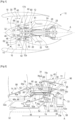
- FIG 2 is a larger scale view of part of the figure 1 , and in particular of the zone Z located between the fan disk 32a and the reducer 33, in which an electric machine 62 is installed.
- the electric machine 62 is mounted coaxially downstream of the fan 14.
- this annular-shaped zone Z is delimited radially on the inside by the fan shaft 32 of the reducer and radially on the outside by the elements which internally delimit the flow vein of the primary flow 36.
- These elements comprise on the one hand an annular shell 64 located upstream and an internal annular wall 66 located downstream connected to the radially internal ends of the arms 42.
- the wall 66 extends in the extension of the shell 64 which is an internal shell and which is connected by the annular row of fixed vanes 68 for straightening the primary flow 36 extending in the internal vein to an external shell 70 forming part of the inlet casing 40.
- the ferrules 64, 70 define between them the air inlet of the flow vein of the primary flow 36.
- the ferrule 70 extends between the aforementioned spout 34 and an external annular wall 72 located downstream of the ferrule 70 and which forms part of the inlet casing 40 because it is connected to the radially external ends of the arms 42.
- the ferrule 64 is therefore surrounded by the inlet casing 40 which delimits with this ferrule 64 a section of the flow vein of the primary flow 36.
- the annular zone Z is divided into two annular portions, respectively upstream and downstream, by the bearing support 52.
- this support has a generally truncated cone shape flared towards the downstream. Its upstream and radially internal end carries the external ring of the bearing 46, the internal ring of which is fixed to the fan shaft 32. The downstream and radially external end of the support 52 is fixed to the inlet casing 40.
- the outer ring of the or each bearing 48 is fixed to the support 52, substantially in its middle, the or each inner ring being fixed to the fan shaft 32.
- the bearing support 52 comprises two annular sections, respectively upstream 52a, and downstream 52b.
- the upstream section 52a extends from the bearing 46 to a radially external annular flange 52aa
- the downstream section 52b extends from a radially internal annular flange 52ba to a radially external annular flange 52bb for fixing to the upstream end of the inlet casing 40.
- each outer ring of the bearing 48 is fixed to a ring 74 which comprises a radially outer annular flange 74a interposed between the flanges 52aa and 52ba.
- a ring 74 which comprises a radially outer annular flange 74a interposed between the flanges 52aa and 52ba.
- These flanges 52aa, 74a, 52ba are applied axially against each other and comprise orifices for the passage of fixing means of the screw-nut type.
- zone Z represents a part of a lubrication enclosure for bearings 46, 48 and 50 as well as for the reducer 33 which is housed in this enclosure, being arranged axially between bearings 46, 48, on the one hand, and bearing 50, on the other hand.
- the upstream portion of the zone Z represents the installation location of the electrical machine 62, which is therefore isolated from the enclosure E by the bearing support 52.
- the machine 62 has a generally annular shape and comprises a rotor 62a and a stator 62b.
- the rotor 62a has a generally cylindrical shape extending around the axis A and is carried by a support element 76 which itself has a generally cylindrical shape.
- the rotor 62a is arranged around this element 76.
- the stator 62b also has a generally cylindrical shape and is integrated into an annular member 78 with a generally C-shaped axial section.
- This member 78 comprises two annular parts, respectively internal 78b and external 78a, which extend around each other and whose downstream ends are connected to each other by an annular bottom 78c.
- the member 78 thus defines an opening which is here oriented axially upstream and in which the rotor 62a and the support element 76 are housed.
- the stator 62b is integrated into the external part 78a of the member or forms this external part 78a.
- This external part 78a is surrounded, here directly by the ferrule 64.
- the portion 78b of the member 78 extends radially inside the rotor 62a and the support element 76 and bearings 80, 82 are mounted between this element 76 and the portion 78b in order to guide the rotor 62a in rotation with respect to the stator 62b.
- the portion 78b thus forms a support for the bearings 80, 82.
- the bearings 80, 82 are here two in number and spaced axially from each other.
- the upstream bearing 80 is a roller bearing and the downstream bearing 82 is a ball bearing.
- An annular closing element 84 is attached and fixed to the upstream end of the support element 76.
- This closing element 84 has a general radial orientation and is fixed by its external periphery to the upstream end of the element 76.
- the element 84 comprises at its external periphery a cylindrical rim 84a which is clamped axially against an internal annular rib of the support element 76 by a nut 86 attached axially from upstream.
- the inner periphery of the element 84 has an inner diameter smaller than the main inner diameter of the part 78b of the member and carries a series of internal rectilinear grooves 88.
- the inner periphery of the element 84 further comprises an annular web 84b extending axially downstream and cooperating in a sealing manner with the upstream end of the part 78b. The sealing is ensured by a labyrinth seal whose annular lips are for example carried by the web 84b and the abradable coating is carried by the part 78b.
- An annular connecting element 90 is used to drive the rotor 62a.
- This element 90 has a generally cylindrical shape and comprises at its end upstream an annular flange 90a for fixing to the fan disk 32, and at its downstream end a series of grooves 90b for coupling to grooves 88 of the closing element 84.
- the grooves 88, 90b can advantageously be of the swivel type to isolate the machine as much as possible from the rest of the engine.
- the bearings 80, 82 are advantageously lubricated and are located in a mini annular lubrication enclosure which is sealed upstream by the seal between the web 84b and the part 78b, and downstream by the seal between a web 78ca and the element 76.
- the lubricating oil of the bearings 80, 82 is intended to be evacuated from this mini enclosure by axial holes 92 provided in the bottom 78c, just at the internal periphery of the webs 78ca and 78cb. These holes 92 allow the oil to penetrate an annular space extending between the bottom 78c and the section 52b of the bearing support 52.
- Axial holes 94 are further provided on this section 52b, substantially opposite the holes 92, so that this oil penetrates into the enclosure and is evacuated as part of the evacuation of oil from this enclosure. It is therefore understood that the lubricating oil of the bearings 80, 82 will flow by centrifugation to the veil 78ca, will pass through the holes 92, will flow over the veil 78cb, then will pass through the holes 94 to reach the lubrication enclosure of the reducer 33.
- the oil can be evacuated through one of the arms 42 of the input casing 40. Another of the arms 42 can be used to convey the supply oil of the bearings 80, 82, to the aforementioned mini enclosure.
- the stator 62b is connected by an electric cable 96 to a control circuit, this cable 96 passing here through a tubular arm 42 of the input casing 40.
- the stator 62b is carried by the annular ferrule 64.
- the electric machine 62 is therefore in direct contact with the shell 64 and with the blades 42, 68 via the shell 64.
- the electric machine 62 can thus be cooled by the primary flow 36 coming into contact with the shell 64 and the blades 42, 68.
- the ferrule 64 and/or the blades 42, 68 comprise elements 100 configured to generate disturbances in the primary flow 36.
- the elements 100 are configured to increase the exchange coefficient h and/or the exchange surface S between the primary flow 36 and the electric machine.
- the exchange surfaces between the primary flow 36 and the electric machine comprise the surface of the internal vein of the casing surrounding the stator of the electric machine, i.e. the surface of the shell 64 as well as the surface of the blades 42, 68 which act as cooling fins.
- the elements 100 are thus located on one or more exchange surfaces 150 located on the shell 64 and/or the blades 42, 68 intended to be swept by the primary flow 36.
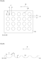
- the elements 100 are for example formed in a hollow or protruding shape on the surface(s) 150 of the shell 64 and/or the blades 42, 68.
- the hollow or protruding shape of the elements 100 makes it possible both to act as a disruptor of the primary flow 36 so as to increase the exchange coefficient and to increase the exchange surface between the primary flow and the electric machine.
- the surface 150 or each of the surfaces 150 comprises for example a matrix of identical hollow elements 100 distributed in rows and columns.
- Each of the elements 100 has for example in cross section a concave curved shape and represents a particular example of hollow-shaped elements. This is a structure “golf ball” type with a succession of hollows of depth and diameter to be determined according to the cooling requirement.
- Each of the elements 100 here has a width or dimension D measured according to the flow direction of the primary flow 36 and is between 2 and 30 mm, and a depth P less than or equal to D.
- the elements 100 are spaced apart by a dimension L1 in the flow direction of the primary flow 36 and by a dimension L3 in a direction perpendicular to the flow direction of the primary flow 36.
- the parameters D, L1, L2 and P are chosen in order to have the best compromise between the criteria of cooling performance, manufacturing, aerodynamic impact in the vein, and cost. Furthermore, these dimensions can also be variable in the surface 150 for optimal sizing.
- All or part of the surface 150 can benefit from this modeling.
- the surface of the ferrule 64 will be preferred over the surfaces of the blades 42, 68, in order to limit the impact on performance.
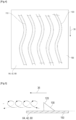
- the surface 150 or each of the surfaces 150 comprises, for example, a series of elements 100 in the form of elongated grooves 110 extending substantially in a flow direction of the primary flow 36. They extend longitudinally, in particular in the flow direction of the primary flow 36. It will be preferable to make grooves in the flow direction so as not to disturb the flow in the vein too much, but grooves orthogonal to the flow direction can also be envisaged.
- the elements 100 in the form of grooves 110 make it possible to increase the exchange surface and the exchange coefficient and therefore to improve the cooling of the electric machine.
- the 110 grooves integrated into the cooling surface can be straight or wavy in order to allow even more exchange surface.
- the groove-shaped elements 100 can be positioned on all or part of the surface 150 to increase its surface area.
- elements 100 in the form of a groove 110 makes it possible to simplify the manufacture of the surfaces 150 as well as to limit the mass of material, it is also possible to provide elements 100 in the form of bridges on the surface(s) 150, in particular by adding material.
- the surface 150 or each of the surfaces 150 may comprise a series of projecting elements 100 formed by fins 120.
- these fins 120 increase the exchange coefficient and therefore the exchange capacity without causing as much pressure loss as a complete modeling of the surface 150.
- the turbulence makes it possible to set the air close to the surface 150 in motion. The heated air does not stagnate, it moves by turbulence towards the colder secondary flow, before returning against the surface 150. The vortex thus created renews the cold air in contact with the hot surface 150 of the shell of the electric machine.
- the 120 fins for example, have a triangular or delta shape which promotes the generation of powerful vortices.
- the fins 120 will generate a pressure loss like an exchanger fin but are here mobile or retractable so as to regulate the disturbances in the primary flow 36.
- the circumferential density of the 120 fins will depend on the desired level of heat exchange and pressure loss.
- 120 fins may be placed in several rows to maximize heat exchange.
- the embodiment example here includes elements 100 in the form of a fin 120 but several other forms of disruptors may be possible. preferably, the elements 100 are “vortex generator” type disruptors as are the fins 120.
- the elements 100 comprise plasma generation actuators 130 on the or each of the surfaces intended to be swept by the primary flow 36.
- the actuators 130 are ideally powered by the electrical machine 62, but another electrical source can also power them. They each comprise a covered electrode 131 and an exposed electrode 132 offset from each other in the flow direction of the primary flow 36.
- the covered electrode 131 is separated from the exposed electrode 132 by a dielectric material 133 and is located in a support 134.
- the actuators 130 are regularly distributed around the electric machine 62, for example on the circumference of the shell.
- the plasma actuator 130 activated via the application of an electric current, induces a disturbance of the local flow speed, which will be developed downstream in turbulence. It makes it possible to set the primary flow 36 in motion without the need for any mechanical part and without generating significant heat. Placed along the circumference of the shell, compared to the other flow control techniques previously presented, these electric actuators 130 devoid of moving parts make it possible to accelerate the air on the shell and the blades 42, 68 and therefore to increase the heat exchanges, without or almost, themselves disturbing the flow of the primary flow 36 when they are not activated. On the other hand, the use of these actuators 130 allows active control of the cooling efficiency by sending more or less, or even no electric current at all, in order to more or less disturb the flow of the primary flow 36.
- zone Z is located downstream of the reducer 33 and upstream of the intermediate casing 61.
- This annular zone Z is delimited radially on the inside by the main shaft 58 of the low pressure body 12a as well as by the input shaft 56 of the reducer 33, and radially to the outside by the elements which internally delimit the flow vein I of the primary flow 36.
- These elements comprise, from upstream to downstream, on the one hand an internal annular wall 66a, an annular shroud 64a, then disks 172a of wheels 172 and internal platforms 174a of the bladed rectifiers 174 of the low pressure compressor 20.
- the wall 66a surrounds the reducer 33 and is part of the input housing 40 because it is connected to the radially internal ends of the arms 42, the radially external ends of which are connected to another external annular wall 66b.
- the ferrule 64a extends around the electric machine 62 and in the extension of the wall 66a.
- the shell 64a is an inner shell and is surrounded by an outer shell 64b, the shells 64a, 64b defining between them a portion of the flow path I of the primary flow 36 downstream of the inlet casing 40 and upstream of the low-pressure compressor 20 and the intermediate casing 61.
- the shell 64b extends from the downstream end of the wall 66b to a wall 20a which surrounds the wheels 172 and the rectifiers 174 of the low-pressure compressor 20.
- the shell 64b can be connected or formed in one piece with this wall 20a.
- this wall 20a comprises on the one hand means 176 for guiding in rotation and for variable setting of the vanes of the rectifiers 174 around substantially radial axes, and abradable annular coatings 178 surrounding the wheels 172.
- the ferrule 64a has its downstream end which is also connected or fixed to means 176 for guiding the rotation of the rectifier blades 174 around the same axes.
- the discs 172a of the wheels 172 of the compressor 20 are fixed to a journal 188 which is driven by the shaft 58 via an intermediate shaft 190.
- the journal 188 has an annular shape and has a general T-shape in axial section.
- the journal 188 comprises a radial annular branch 188a whose internal periphery is connected to a cylindrical branch 188b.
- the external periphery of the radial branch 188a is fixed by screws to flanges discs 172a of the wheels 172, and the cylindrical branch 188b comprises internal splines 188c for coupling to external splines of the intermediate shaft 190.
- the intermediate shaft 190 has a generally tubular shape and comprises an upstream section 190a and a downstream section 190b.
- the journal 188 is mounted on the downstream section 190b of the intermediate shaft 190, this downstream section 190b comprising internal splines 190c for coupling to external splines of the main shaft 58, as well as a cylindrical shoulder 190d for axial support downstream of the journal 188 and in particular of the downstream end of its cylindrical branch 188b.
- the intermediate shaft 190 may further comprise an external cylindrical surface 190e for centering the branch 188b and therefore of the journal 188.
- the upstream section 190a of the intermediate shaft 190 extends around the downstream end of the input shaft 56 of the reducer 33.
- This input shaft 56 comprises internal splines 56a for coupling with external splines of the main shaft 58.
- a nut 192 is tightened axially at the upstream end of the main shaft 58 and bears axially on the input shaft 56 to tighten it axially against the intermediate shaft 190 which itself bears axially on a cylindrical shoulder 170a of the main shaft 58.
- the intermediate shaft 190 carries the inner ring 50a of the bearing 50, here with balls, the outer ring 50b of which is carried by the bearing support 60.
- This support 60 has a generally truncated cone shape and is flared axially downstream. Its downstream end of larger diameter is fixed to the intermediate casing 61.
- This type of bearing 50 is conventionally lubricated and is located in an annular lubrication enclosure which is sealed to prevent any oil leakage, particularly upstream, in the zone Z where the electric machine 62 is located.
- the rotor 62a is here fixed to an annular member 194 extending around the axis A.
- the member 194 has a general T shape in axial section.
- the member 194 comprises a radial annular branch 194a whose internal periphery is connected to a cylindrical branch 194b.
- the outer periphery of the radial branch 194a is fixed by screws to the rotor 62a, and the cylindrical branch 94b comprises internal splines 194c for coupling to external splines of the intermediate shaft 190, and in particular of its upstream section 190a.
- the downstream end of the cylindrical branch 194b is on the one hand in axial support on the upstream end of the cylindrical branch 188b of the journal 188, and cooperates on the other hand with the cylindrical centering surface 190e carried by the intermediate shaft 190.
- a nut 196 is tightened axially at the upstream end of the intermediate shaft 190 and bears axially on the member 194 to urge it axially against the journal 188.
- the cylindrical branch 194b of the member 194 carries an internal ring 198a of a bearing 198, here with rollers, the external ring 198b of which is carried by another annular bearing support 200.
- This support 200 has a generally truncated cone shape and is axially flared towards the upstream. Its upstream end of larger diameter is fixed to the stator 62b of the electric machine 62.
- the stator 62b comprises at its upstream end a radially internal annular flange for fixing several flanges including one 200a of the bearing support 200.
- the flange 62ba of the stator 62b is also fixed to a flange 40a of the input casing 40, as well as to flanges of sealing covers 202 and/or deflectors.
- the inner periphery of the bearing support 200 may be equipped with an oil film damping system 204, known as squeeze-film. It may further comprise a cylindrical rim 200b oriented downstream and comprising an internal annular coating made of abradable material.
- Two annular sealing covers 206 can be fixed to the member 194 and in particular to its radial branch 194a, and carry radially external annular wipers intended to cooperate on the one hand with the coating carried by the rim 200b, as well as with a similar coating carried by one of the covers 202 fixed to the flange 62ba of the stator 62b.
- the bearing 198 is conventionally lubricated and is located in an annular lubrication enclosure which is sealed to prevent any oil leakage, particularly downstream, in the zone Z where the electric machine 62 is located.
- the stator 62b is connected by an electric cable 96 to a control circuit, this cable 96 passing here through a tubular arm 42 of the input casing 40.
- the electric machine 62 and in particular its stator 62b is located as close as possible to the primary flux 36 as in the exemplary embodiment illustrated in figure 2 , thus making it possible to have a machine which is cooled by the primary flow 36.
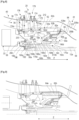
- FIG 8 illustrates an alternative embodiment of a turbomachine according to the invention.
- the zone Z of implantation of the electric machine 62 is here located downstream of the reducer 33 and the compressor 20, and upstream of the intermediate casing 61.
- This annular-shaped zone Z is delimited radially on the inside by the main shaft 58 of the low-pressure body 12a as well as by the input shaft 56 of the reducer 33, and radially on the outside by the elements which internally delimit the flow path I of the primary flow 36.
- These elements here comprise, from upstream to downstream, the disks 172a of the wheels 172 and the internal platforms 174a of the bladed rectifiers 174 of the low-pressure compressor 20, the annular shroud 64a, then an internal annular wall 208b.
- the wall 208b is part of the intermediate casing because it is connected to the radially internal ends of arms 210 whose radially external ends are connected to another external annular wall 208a.
- the shell 64a extends around the electric machine 62 and in the extension of the disks 172a of the wheels 172 and the internal platforms 174a of the bladed rectifiers 174 of the compressor 20.
- the shell 64a is an internal shell and is surrounded by an external shell 64b, the shells 64a, 64b defining between them a portion of the flow vein I of the primary flow 36 downstream of the low pressure compressor 20. and upstream of the intermediate casing 61.
- the ferrule 64b extends from the downstream end of the wall 20a to an outer annular wall 208a which is connected to the radially outer ends of the arms 210 and therefore forms part of the intermediate casing 61.
- the ferrule 64b may be connected or formed in one piece with the wall 20a.
- this wall 20a comprises on the one hand means 176 for guiding in rotation and for variable setting of the vanes of the rectifiers 174 around substantially radial axes, and abradable annular coatings 178 surrounding the wheels 172.
- the ferrule 64a comprises at its upstream end a cylindrical rim 212 oriented upstream and carrying an annular coating of abradable material intended to cooperate with wipers 180d carried by the disk 172a of the downstream wheel of the compressor 20.
- the discs 172a of the wheels 172 of the compressor 20 are fixed to a journal 188 which is driven by the shaft 58 via an intermediate shaft 190.
- the stator 62b comprises at its downstream end an annular flange 62ba for fixing several flanges including one of the internal annular wall 208b.
- the flange 62ba of the stator 62b is also fixed to a flange of the bearing support 60.
- the inner periphery of the bearing support 60 can be equipped with an oil film damping system 204, known as squeeze-film.
- the bearing 198 is conventionally lubricated and is located in an annular lubrication enclosure which is sealed to prevent any oil leakage, particularly downstream, in the zone Z where the electric machine 62 is located.
- the stator 62b is connected by an electric cable 96 to a control circuit, this cable 96 passing here through a tubular arm 110 of the intermediate casing 61.
- the ferrule 64a which extends, preferably directly, around the stator 62b, has its radially external surface which is swept by the flow 36.
- the ferrule 64a ensures the exchange of calories by thermal conduction between the stator 62b and the flow 36.
- the elements 100 could then for example be located on the ferrule 64a and/or on the bladed rectifiers 174.
- FIG 9 illustrates another variant embodiment of the invention.
- the zone Z of installation of the electric machine 62 is here similar to that of the embodiment of the figure 8 .
- the 62 electric machine is similar to that of the figure 8 except that the cover C of its stator 62b is separate from the ferrule 64a.
- the other characteristics of this variant embodiment are similar to those of the embodiment of the figure 8 .
Landscapes
- Engineering & Computer Science (AREA)
- Mechanical Engineering (AREA)
- General Engineering & Computer Science (AREA)
- Power Engineering (AREA)
- Structures Of Non-Positive Displacement Pumps (AREA)
- Motor Or Generator Cooling System (AREA)
- Connection Of Motors, Electrical Generators, Mechanical Devices, And The Like (AREA)
- Physics & Mathematics (AREA)
- Thermal Sciences (AREA)
Claims (15)
- Turbotriebwerk (10) eines Luftfahrzeugs, umfassend einen Gasgenerator (12) und ein Gebläse, das dem Gasgenerator (12) vorgelagert und konfiguriert ist, um einen Eintritts-Gasstrom (F) zu erzeugen, von dem ein Teil in einer Vene des Gasgenerators fließt, um einen primären Strom (36) zu bilden, und von dem ein anderer Teil in einer Vene um den Gasgenerator (12) herum fließt, um einen sekundären Strom (38) zu bilden, wobei das Turbotriebwerk (10) ferner eine elektrische Maschine (62) umfasst, die dem Gebläse (14) nachgelagert koaxial montiert ist und die einen Rotor (62a), der von einem Stator (62b) umgeben ist, der von einem ringförmigen Haltering (64, 64a) getragen wird, umfasst, wobei dieser Haltering (64, 64a) von einem Gehäuse (40) des Gasgenerators (12) umgeben wird, das mit diesem Haltering (64, 64a) einen Abschnitt der Durchflussvene des primären Stroms (36) abgrenzt, feste Schaufeln (42, 68, 174) zur Begradigung dieses primären Stroms (36), der sich in dieser Vene erstreckt, umfasst, wobei die elektrische Maschine (62) mit dem Haltering (64) und mittels des Halterings (64) mit den Schaufeln (42, 68, 174) in direktem Kontakt vorliegt, dadurch gekennzeichnet, dass der Haltering (64, 64a) und/oder die Schaufeln (42, 68, 174) Elemente (100) umfassen, die konfiguriert sind, um Perturbationen in dem primären Strom (36) zu erzeugen.
- Turbotriebwerk (10) nach Anspruch 1, wobei die Elemente (100) vertieft oder auf einer oder den Oberflächen (150) des Halterings (64, 64a) und/oder der Schaufeln (42, 68, 174) hervorstehend gebildet sind, wobei die Oberfläche (150) oder jede dieser Oberflächen (150) dazu bestimmt ist, durch den primären Strom (36) angeströmt zu werden.
- Turbotriebwerk (10) nach Anspruch 2, wobei die Oberfläche (150) oder jede der Oberflächen (150) eine Matrix von identischen vertieften Elementen (100) umfasst, die in Reihen und Spalten verteilt sind.
- Turbotriebwerk (10) nach Anspruch 3, wobei jedes der Elemente (100) im Querschnitt eine konkav gekrümmte Form aufweist.
- Turbotriebwerk (10) nach Anspruch 3 oder 4, wobei jedes der Elemente (100) eine Breite oder Abmessung D zwischen 2 und 30 mm und eine Tiefe P kleiner als oder gleich D aufweist.
- Turbotriebwerk (10) nach Anspruch 2, wobei die Oberfläche (150) oder jede der Oberflächen (150) eine Reihe von Elementen (100) in Form von länglichen Rillen (110) umfasst, die sich im Wesentlichen in einer Durchflussrichtung des primären Stroms (36) erstrecken.
- Turbotriebwerk (10) nach Anspruch 6, wobei die Rillen (110) wellenförmig sind.
- Turbotriebwerk (10) nach Anspruch 2, wobei die Oberfläche (150) oder jede der Oberflächen (150) eine Reihe von hervorstehenden Elementen (100) umfasst, die durch Rippen (120) gebildet sind.
- Turbotriebwerk (10) nach Anspruch 8, wobei die Rippen (120) eine dreieckige oder Delta-Form aufweisen.
- Turbotriebwerk (10) nach Anspruch 8 oder 9, wobei die Rippen (120) derart beweglich oder zurückziehbar sind, um die Perturbationen in der primären Strömung (36) zu regeln.
- Turbotriebwerk (10) nach einem der vorstehenden Ansprüche, wobei die Elemente (100) Aktuatoren (130) zum Erzeugen von Plasma auf der oder jeder der Oberfläche(n) (150) umfassen, die dazu bestimmt ist/sind, von dem primären Strom (36) angeströmt zu werden.
- Turbotriebwerk (10) nach Anspruch 11, wobei die Aktuatoren (130) von der elektrischen Maschine (62) gespeist werden.
- Turbotriebwerk (10) nach Anspruch 11 oder 12, wobei die Aktuatoren (130) gleichmäßig um die elektrische Maschine (62) herum verteilt sind.
- Turbotriebwerk (10) nach einem der vorstehenden Ansprüche, wobei der Haltering (64, 64a) eine interne ringförmige Oberfläche, die den Stator (62b) der elektrischen Maschine (62) umgibt, und eine externe ringförmige Oberfläche umfasst, die sich um die interne ringförmige Oberfläche herum erstreckt und die den Abschnitt der Durchflussvene des primären Stroms (36) definiert.
- Turbotriebwerk (10) nach einem der vorstehenden Ansprüche, wobei die Elemente (100) durch ein oder mehrere wärmeleitende(s) Stück(e) an dem Stator (62b) derart verbunden sind, um einen Wärmeaustausch durch Konduktion sicherzustellen.
Applications Claiming Priority (2)
| Application Number | Priority Date | Filing Date | Title |
|---|---|---|---|
| FR2002896A FR3108654B1 (fr) | 2020-03-25 | 2020-03-25 | Turbomachine d’aeronef equipee d’une machine electrique |
| PCT/FR2021/050489 WO2021191553A1 (fr) | 2020-03-25 | 2021-03-23 | Turbomachine d'aeronef equipee d'une machine electrique |
Publications (2)
| Publication Number | Publication Date |
|---|---|
| EP4127412A1 EP4127412A1 (de) | 2023-02-08 |
| EP4127412B1 true EP4127412B1 (de) | 2025-01-29 |
Family
ID=70614262
Family Applications (1)
| Application Number | Title | Priority Date | Filing Date |
|---|---|---|---|
| EP21717150.3A Active EP4127412B1 (de) | 2020-03-25 | 2021-03-23 | Turbomaschine eines luftfahrzeugs, ausgestattet mit einer elektromaschine |
Country Status (5)
| Country | Link |
|---|---|
| US (1) | US12289035B2 (de) |
| EP (1) | EP4127412B1 (de) |
| CN (1) | CN115315566B (de) |
| FR (1) | FR3108654B1 (de) |
| WO (1) | WO2021191553A1 (de) |
Families Citing this family (4)
| Publication number | Priority date | Publication date | Assignee | Title |
|---|---|---|---|---|
| FR3114351B1 (fr) * | 2020-09-18 | 2022-08-12 | Safran Aircraft Engines | Raccordement electrique d’une machine electrique dans une turbomachine d’aeronef |
| WO2022228734A2 (de) * | 2021-04-26 | 2022-11-03 | Malte Schwarze | Effiziente schubkrafterzeugung |
| CN116641797B (zh) * | 2023-05-19 | 2026-01-30 | 南京航空航天大学 | 一种行星齿轮式动力组件的滑油润滑冷却装置及方法 |
| US20250369367A1 (en) * | 2024-05-29 | 2025-12-04 | Rtx Corporation | Cooling features for a component of a gas turbine engine |
Family Cites Families (13)
| Publication number | Priority date | Publication date | Assignee | Title |
|---|---|---|---|---|
| GB1041587A (en) * | 1962-08-27 | 1966-09-07 | Bristol Siddeley Engines Ltd | Improvements in gas turbine engines |
| US5334897A (en) * | 1993-05-24 | 1994-08-02 | North American Philips Corporation | Electric motor with encased housing |
| FR2842565B1 (fr) | 2002-07-17 | 2005-01-28 | Snecma Moteurs | Demarreur-generateur integre pour turbomachine |
| US7874163B2 (en) | 2004-12-01 | 2011-01-25 | United Technologies Corporation | Starter generator system for a tip turbine engine |
| FR2922265B1 (fr) * | 2007-10-12 | 2013-11-22 | Snecma | Turboreacteur incorporant un generateur de courant electrique. |
| US8375695B2 (en) | 2009-06-30 | 2013-02-19 | General Electric Company | Aircraft gas turbine engine counter-rotatable generator |
| EP2407638A1 (de) * | 2010-07-15 | 2012-01-18 | Siemens Aktiengesellschaft | Abgasdiffusor für eine Gasturbine und Verfahren zum Betreiben einer Gasturbine mit einem solchen Abgasdiffusor |
| US9109452B2 (en) * | 2012-06-05 | 2015-08-18 | United Technologies Corporation | Vortex generators for improved film effectiveness |
| WO2015077755A1 (en) * | 2013-11-25 | 2015-05-28 | United Technologies Corporation | Film cooled multi-walled structure with one or more indentations |
| EP2963241B1 (de) * | 2014-06-30 | 2019-03-06 | Safran Aero Boosters SA | Leitelement für die Gaströmung in einer Strömungsmaschine |
| US10801410B2 (en) * | 2018-04-12 | 2020-10-13 | Raytheon Technologies Corporation | Thermal management of tail cone mounted generator |
| US10978934B2 (en) * | 2018-08-27 | 2021-04-13 | General Electric Company | Engine with a permanent magnet electric machine |
| WO2021065100A1 (ja) * | 2019-09-30 | 2021-04-08 | 株式会社Ihi | 発電機及び当該発電機を備える航空機用多軸式ガスタービンエンジン |
-
2020
- 2020-03-25 FR FR2002896A patent/FR3108654B1/fr active Active
-
2021
- 2021-03-23 US US17/908,748 patent/US12289035B2/en active Active
- 2021-03-23 CN CN202180022941.3A patent/CN115315566B/zh active Active
- 2021-03-23 WO PCT/FR2021/050489 patent/WO2021191553A1/fr not_active Ceased
- 2021-03-23 EP EP21717150.3A patent/EP4127412B1/de active Active
Also Published As
| Publication number | Publication date |
|---|---|
| US20230125576A1 (en) | 2023-04-27 |
| WO2021191553A1 (fr) | 2021-09-30 |
| EP4127412A1 (de) | 2023-02-08 |
| CN115315566B (zh) | 2025-08-22 |
| CN115315566A (zh) | 2022-11-08 |
| FR3108654A1 (fr) | 2021-10-01 |
| FR3108654B1 (fr) | 2022-03-04 |
| US12289035B2 (en) | 2025-04-29 |
Similar Documents
| Publication | Publication Date | Title |
|---|---|---|
| EP4127412B1 (de) | Turbomaschine eines luftfahrzeugs, ausgestattet mit einer elektromaschine | |
| EP3870810B1 (de) | Gebläsemodul ausgerüstet mit einer elektrischen maschine für eine turbomaschine eines luftfahrzeugs | |
| EP3575562B1 (de) | Leistungsübertragungssystem, das eine schmierölrückgewinnungsvorrichtung umfasst, und mit einem solchen leistungsübertragungssystem ausgestattetes turbotriebwerk | |
| EP3682141B1 (de) | Drehpunkt für ein gleitlager und verfahren zur herstellung | |
| FR3087223A1 (fr) | Turbomachine a turbine contrarotative pour un aeronef | |
| EP3870813A1 (de) | Flugzeugturbinentriebwerk mit einer elektrischen maschine | |
| FR3104193A1 (fr) | Recuperation d’huile de lubrification d’un reducteur de turbomachine d’aeronef | |
| WO2020084219A1 (fr) | Turbomachine d'aeronef equipee d'une machine electrique | |
| BE1024941A1 (fr) | Controle actif de jeu pour compresseur de turbomachine | |
| EP2917518B1 (de) | Aufnahme eines entlüftungsrohr einer turbomachine | |
| EP4069945B1 (de) | Starre stange zur elektrischen verbindung einer maschine in einem flugtriebwerk | |
| EP4069948B1 (de) | Elektrisches modul für eine turbomaschine eines flugzeugs | |
| EP4069946B1 (de) | Elektrische verbindung für eine elektrische maschine in einem flugzeugturbinenmotor | |
| EP3870812B1 (de) | Flugzeugturbomaschine ausgerüstet mit einer elektrischen maschine | |
| EP3682140B1 (de) | Drehpunkt für gleitlager und zahnradgetriebe | |
| EP4102109A1 (de) | Mechanisches bauteil für turbotriebwerk eines luftfahrzeugs und entsprechendes turbotriebwerk | |
| FR3055354B1 (fr) | Turbomachine comprenant des moyens d'etancheite et procede de montage de la turbomachine correspondant | |
| FR2491137A1 (fr) | Mecanisme de turbines a gaz | |
| EP4073364B1 (de) | Turbomaschine mit gegenläufiger turbine für ein flugzeug | |
| EP4605640A1 (de) | Turbomaschine mit einem wärmetauscher ausgestattetem rekuperationszyklus | |
| WO2023111466A1 (fr) | Echangeur de chaleur a double etage et turbomachine equipee d'un tel echangeur de chaleur | |
| FR2953486A1 (fr) | Moyeu d'helice a anneau polygonal plein et turbomachine equipee d'un tel moyeu |
Legal Events
| Date | Code | Title | Description |
|---|---|---|---|
| STAA | Information on the status of an ep patent application or granted ep patent |
Free format text: STATUS: UNKNOWN |
|
| STAA | Information on the status of an ep patent application or granted ep patent |
Free format text: STATUS: THE INTERNATIONAL PUBLICATION HAS BEEN MADE |
|
| PUAI | Public reference made under article 153(3) epc to a published international application that has entered the european phase |
Free format text: ORIGINAL CODE: 0009012 |
|
| STAA | Information on the status of an ep patent application or granted ep patent |
Free format text: STATUS: REQUEST FOR EXAMINATION WAS MADE |
|
| 17P | Request for examination filed |
Effective date: 20220923 |
|
| AK | Designated contracting states |
Kind code of ref document: A1 Designated state(s): AL AT BE BG CH CY CZ DE DK EE ES FI FR GB GR HR HU IE IS IT LI LT LU LV MC MK MT NL NO PL PT RO RS SE SI SK SM TR |
|
| DAV | Request for validation of the european patent (deleted) | ||
| DAX | Request for extension of the european patent (deleted) | ||
| GRAP | Despatch of communication of intention to grant a patent |
Free format text: ORIGINAL CODE: EPIDOSNIGR1 |
|
| STAA | Information on the status of an ep patent application or granted ep patent |
Free format text: STATUS: GRANT OF PATENT IS INTENDED |
|
| GRAS | Grant fee paid |
Free format text: ORIGINAL CODE: EPIDOSNIGR3 |
|
| INTG | Intention to grant announced |
Effective date: 20241115 |
|
| GRAA | (expected) grant |
Free format text: ORIGINAL CODE: 0009210 |
|
| STAA | Information on the status of an ep patent application or granted ep patent |
Free format text: STATUS: THE PATENT HAS BEEN GRANTED |
|
| AK | Designated contracting states |
Kind code of ref document: B1 Designated state(s): AL AT BE BG CH CY CZ DE DK EE ES FI FR GB GR HR HU IE IS IT LI LT LU LV MC MK MT NL NO PL PT RO RS SE SI SK SM TR |
|
| REG | Reference to a national code |
Ref country code: GB Ref legal event code: FG4D Free format text: NOT ENGLISH |
|
| REG | Reference to a national code |
Ref country code: CH Ref legal event code: EP |
|
| REG | Reference to a national code |
Ref country code: DE Ref legal event code: R096 Ref document number: 602021025382 Country of ref document: DE |
|
| REG | Reference to a national code |
Ref country code: IE Ref legal event code: FG4D Free format text: LANGUAGE OF EP DOCUMENT: FRENCH |
|
| PGFP | Annual fee paid to national office [announced via postgrant information from national office to epo] |
Ref country code: DE Payment date: 20250218 Year of fee payment: 5 |
|
| PGFP | Annual fee paid to national office [announced via postgrant information from national office to epo] |
Ref country code: AT Payment date: 20250417 Year of fee payment: 5 |
|
| PGFP | Annual fee paid to national office [announced via postgrant information from national office to epo] |
Ref country code: FR Payment date: 20250219 Year of fee payment: 5 |
|
| PGFP | Annual fee paid to national office [announced via postgrant information from national office to epo] |
Ref country code: GB Payment date: 20250220 Year of fee payment: 5 |
|
| REG | Reference to a national code |
Ref country code: NL Ref legal event code: MP Effective date: 20250129 |
|
| PG25 | Lapsed in a contracting state [announced via postgrant information from national office to epo] |
Ref country code: NL Free format text: LAPSE BECAUSE OF FAILURE TO SUBMIT A TRANSLATION OF THE DESCRIPTION OR TO PAY THE FEE WITHIN THE PRESCRIBED TIME-LIMIT Effective date: 20250129 |
|
| PG25 | Lapsed in a contracting state [announced via postgrant information from national office to epo] |
Ref country code: RS Free format text: LAPSE BECAUSE OF FAILURE TO SUBMIT A TRANSLATION OF THE DESCRIPTION OR TO PAY THE FEE WITHIN THE PRESCRIBED TIME-LIMIT Effective date: 20250429 |
|
| PG25 | Lapsed in a contracting state [announced via postgrant information from national office to epo] |
Ref country code: FI Free format text: LAPSE BECAUSE OF FAILURE TO SUBMIT A TRANSLATION OF THE DESCRIPTION OR TO PAY THE FEE WITHIN THE PRESCRIBED TIME-LIMIT Effective date: 20250129 |
|
| PG25 | Lapsed in a contracting state [announced via postgrant information from national office to epo] |
Ref country code: PL Free format text: LAPSE BECAUSE OF FAILURE TO SUBMIT A TRANSLATION OF THE DESCRIPTION OR TO PAY THE FEE WITHIN THE PRESCRIBED TIME-LIMIT Effective date: 20250129 |
|
| PG25 | Lapsed in a contracting state [announced via postgrant information from national office to epo] |
Ref country code: ES Free format text: LAPSE BECAUSE OF FAILURE TO SUBMIT A TRANSLATION OF THE DESCRIPTION OR TO PAY THE FEE WITHIN THE PRESCRIBED TIME-LIMIT Effective date: 20250129 |
|
| REG | Reference to a national code |
Ref country code: LT Ref legal event code: MG9D |
|
| PG25 | Lapsed in a contracting state [announced via postgrant information from national office to epo] |
Ref country code: IS Free format text: LAPSE BECAUSE OF FAILURE TO SUBMIT A TRANSLATION OF THE DESCRIPTION OR TO PAY THE FEE WITHIN THE PRESCRIBED TIME-LIMIT Effective date: 20250529 Ref country code: NO Free format text: LAPSE BECAUSE OF FAILURE TO SUBMIT A TRANSLATION OF THE DESCRIPTION OR TO PAY THE FEE WITHIN THE PRESCRIBED TIME-LIMIT Effective date: 20250429 |
|
| REG | Reference to a national code |
Ref country code: AT Ref legal event code: MK05 Ref document number: 1763614 Country of ref document: AT Kind code of ref document: T Effective date: 20250129 |
|
| PG25 | Lapsed in a contracting state [announced via postgrant information from national office to epo] |
Ref country code: HR Free format text: LAPSE BECAUSE OF FAILURE TO SUBMIT A TRANSLATION OF THE DESCRIPTION OR TO PAY THE FEE WITHIN THE PRESCRIBED TIME-LIMIT Effective date: 20250129 |
|
| PG25 | Lapsed in a contracting state [announced via postgrant information from national office to epo] |
Ref country code: LV Free format text: LAPSE BECAUSE OF FAILURE TO SUBMIT A TRANSLATION OF THE DESCRIPTION OR TO PAY THE FEE WITHIN THE PRESCRIBED TIME-LIMIT Effective date: 20250129 Ref country code: PT Free format text: LAPSE BECAUSE OF FAILURE TO SUBMIT A TRANSLATION OF THE DESCRIPTION OR TO PAY THE FEE WITHIN THE PRESCRIBED TIME-LIMIT Effective date: 20250529 |
|
| PG25 | Lapsed in a contracting state [announced via postgrant information from national office to epo] |
Ref country code: GR Free format text: LAPSE BECAUSE OF FAILURE TO SUBMIT A TRANSLATION OF THE DESCRIPTION OR TO PAY THE FEE WITHIN THE PRESCRIBED TIME-LIMIT Effective date: 20250430 Ref country code: BG Free format text: LAPSE BECAUSE OF FAILURE TO SUBMIT A TRANSLATION OF THE DESCRIPTION OR TO PAY THE FEE WITHIN THE PRESCRIBED TIME-LIMIT Effective date: 20250129 |
|
| PG25 | Lapsed in a contracting state [announced via postgrant information from national office to epo] |
Ref country code: AT Free format text: LAPSE BECAUSE OF FAILURE TO SUBMIT A TRANSLATION OF THE DESCRIPTION OR TO PAY THE FEE WITHIN THE PRESCRIBED TIME-LIMIT Effective date: 20250129 |
|
| PG25 | Lapsed in a contracting state [announced via postgrant information from national office to epo] |
Ref country code: SE Free format text: LAPSE BECAUSE OF FAILURE TO SUBMIT A TRANSLATION OF THE DESCRIPTION OR TO PAY THE FEE WITHIN THE PRESCRIBED TIME-LIMIT Effective date: 20250129 |
|
| PG25 | Lapsed in a contracting state [announced via postgrant information from national office to epo] |
Ref country code: SM Free format text: LAPSE BECAUSE OF FAILURE TO SUBMIT A TRANSLATION OF THE DESCRIPTION OR TO PAY THE FEE WITHIN THE PRESCRIBED TIME-LIMIT Effective date: 20250129 |
|
| PG25 | Lapsed in a contracting state [announced via postgrant information from national office to epo] |
Ref country code: DK Free format text: LAPSE BECAUSE OF FAILURE TO SUBMIT A TRANSLATION OF THE DESCRIPTION OR TO PAY THE FEE WITHIN THE PRESCRIBED TIME-LIMIT Effective date: 20250129 |
|
| PG25 | Lapsed in a contracting state [announced via postgrant information from national office to epo] |
Ref country code: MC Free format text: LAPSE BECAUSE OF FAILURE TO SUBMIT A TRANSLATION OF THE DESCRIPTION OR TO PAY THE FEE WITHIN THE PRESCRIBED TIME-LIMIT Effective date: 20250129 |
|
| PG25 | Lapsed in a contracting state [announced via postgrant information from national office to epo] |
Ref country code: IT Free format text: LAPSE BECAUSE OF FAILURE TO SUBMIT A TRANSLATION OF THE DESCRIPTION OR TO PAY THE FEE WITHIN THE PRESCRIBED TIME-LIMIT Effective date: 20250129 |
|
| PG25 | Lapsed in a contracting state [announced via postgrant information from national office to epo] |
Ref country code: EE Free format text: LAPSE BECAUSE OF FAILURE TO SUBMIT A TRANSLATION OF THE DESCRIPTION OR TO PAY THE FEE WITHIN THE PRESCRIBED TIME-LIMIT Effective date: 20250129 Ref country code: CZ Free format text: LAPSE BECAUSE OF FAILURE TO SUBMIT A TRANSLATION OF THE DESCRIPTION OR TO PAY THE FEE WITHIN THE PRESCRIBED TIME-LIMIT Effective date: 20250129 |
|
| REG | Reference to a national code |
Ref country code: CH Ref legal event code: H13 Free format text: ST27 STATUS EVENT CODE: U-0-0-H10-H13 (AS PROVIDED BY THE NATIONAL OFFICE) Effective date: 20251023 |
|
| PG25 | Lapsed in a contracting state [announced via postgrant information from national office to epo] |
Ref country code: RO Free format text: LAPSE BECAUSE OF FAILURE TO SUBMIT A TRANSLATION OF THE DESCRIPTION OR TO PAY THE FEE WITHIN THE PRESCRIBED TIME-LIMIT Effective date: 20250129 |
|
| PG25 | Lapsed in a contracting state [announced via postgrant information from national office to epo] |
Ref country code: SK Free format text: LAPSE BECAUSE OF FAILURE TO SUBMIT A TRANSLATION OF THE DESCRIPTION OR TO PAY THE FEE WITHIN THE PRESCRIBED TIME-LIMIT Effective date: 20250129 |
|
| REG | Reference to a national code |
Ref country code: DE Ref legal event code: R097 Ref document number: 602021025382 Country of ref document: DE |
|
| PG25 | Lapsed in a contracting state [announced via postgrant information from national office to epo] |
Ref country code: LU Free format text: LAPSE BECAUSE OF NON-PAYMENT OF DUE FEES Effective date: 20250323 |
|
| PLBE | No opposition filed within time limit |
Free format text: ORIGINAL CODE: 0009261 |
|
| STAA | Information on the status of an ep patent application or granted ep patent |
Free format text: STATUS: NO OPPOSITION FILED WITHIN TIME LIMIT |
|
| REG | Reference to a national code |
Ref country code: BE Ref legal event code: MM Effective date: 20250331 |
|
| 26N | No opposition filed |
Effective date: 20251030 |
|
| PG25 | Lapsed in a contracting state [announced via postgrant information from national office to epo] |
Ref country code: BE Free format text: LAPSE BECAUSE OF NON-PAYMENT OF DUE FEES Effective date: 20250331 |
|
| PG25 | Lapsed in a contracting state [announced via postgrant information from national office to epo] |
Ref country code: CH Free format text: LAPSE BECAUSE OF NON-PAYMENT OF DUE FEES Effective date: 20250331 |
|
| PG25 | Lapsed in a contracting state [announced via postgrant information from national office to epo] |
Ref country code: IE Free format text: LAPSE BECAUSE OF NON-PAYMENT OF DUE FEES Effective date: 20250323 |