EP4127409B1 - Turbomaschinen-bläserlaufschaufel, bläser und turbomaschine mit einer solchen schaufel - Google Patents
Turbomaschinen-bläserlaufschaufel, bläser und turbomaschine mit einer solchen schaufel Download PDFInfo
- Publication number
- EP4127409B1 EP4127409B1 EP21732359.1A EP21732359A EP4127409B1 EP 4127409 B1 EP4127409 B1 EP 4127409B1 EP 21732359 A EP21732359 A EP 21732359A EP 4127409 B1 EP4127409 B1 EP 4127409B1
- Authority
- EP
- European Patent Office
- Prior art keywords
- upstream
- blade
- metallic
- nose
- recess
- Prior art date
- Legal status (The legal status is an assumption and is not a legal conclusion. Google has not performed a legal analysis and makes no representation as to the accuracy of the status listed.)
- Active
Links
Images

Classifications
-
- F—MECHANICAL ENGINEERING; LIGHTING; HEATING; WEAPONS; BLASTING
- F01—MACHINES OR ENGINES IN GENERAL; ENGINE PLANTS IN GENERAL; STEAM ENGINES
- F01D—NON-POSITIVE DISPLACEMENT MACHINES OR ENGINES, e.g. STEAM TURBINES
- F01D5/00—Blades; Blade-carrying members; Heating, heat-insulating, cooling or antivibration means on the blades or the members
- F01D5/12—Blades
- F01D5/14—Form or construction
- F01D5/147—Construction, i.e. structural features, e.g. of weight-saving hollow blades
-
- F—MECHANICAL ENGINEERING; LIGHTING; HEATING; WEAPONS; BLASTING
- F01—MACHINES OR ENGINES IN GENERAL; ENGINE PLANTS IN GENERAL; STEAM ENGINES
- F01D—NON-POSITIVE DISPLACEMENT MACHINES OR ENGINES, e.g. STEAM TURBINES
- F01D21/00—Shutting-down of machines or engines, e.g. in emergency; Regulating, controlling, or safety means not otherwise provided for
- F01D21/04—Shutting-down of machines or engines, e.g. in emergency; Regulating, controlling, or safety means not otherwise provided for responsive to undesired position of rotor relative to stator or to breaking-off of a part of the rotor, e.g. indicating such position
- F01D21/045—Shutting-down of machines or engines, e.g. in emergency; Regulating, controlling, or safety means not otherwise provided for responsive to undesired position of rotor relative to stator or to breaking-off of a part of the rotor, e.g. indicating such position special arrangements in stators or in rotors dealing with breaking-off of part of rotor
-
- F—MECHANICAL ENGINEERING; LIGHTING; HEATING; WEAPONS; BLASTING
- F01—MACHINES OR ENGINES IN GENERAL; ENGINE PLANTS IN GENERAL; STEAM ENGINES
- F01D—NON-POSITIVE DISPLACEMENT MACHINES OR ENGINES, e.g. STEAM TURBINES
- F01D5/00—Blades; Blade-carrying members; Heating, heat-insulating, cooling or antivibration means on the blades or the members
- F01D5/12—Blades
- F01D5/14—Form or construction
- F01D5/20—Specially-shaped blade tips to seal space between tips and stator
-
- F—MECHANICAL ENGINEERING; LIGHTING; HEATING; WEAPONS; BLASTING
- F01—MACHINES OR ENGINES IN GENERAL; ENGINE PLANTS IN GENERAL; STEAM ENGINES
- F01D—NON-POSITIVE DISPLACEMENT MACHINES OR ENGINES, e.g. STEAM TURBINES
- F01D5/00—Blades; Blade-carrying members; Heating, heat-insulating, cooling or antivibration means on the blades or the members
- F01D5/12—Blades
- F01D5/28—Selecting particular materials; Particular measures relating thereto; Measures against erosion or corrosion
- F01D5/282—Selecting composite materials, e.g. blades with reinforcing filaments
-
- F—MECHANICAL ENGINEERING; LIGHTING; HEATING; WEAPONS; BLASTING
- F04—POSITIVE - DISPLACEMENT MACHINES FOR LIQUIDS; PUMPS FOR LIQUIDS OR ELASTIC FLUIDS
- F04D—NON-POSITIVE-DISPLACEMENT PUMPS
- F04D29/00—Details, component parts, or accessories
- F04D29/26—Rotors specially for elastic fluids
- F04D29/32—Rotors specially for elastic fluids for axial flow pumps
- F04D29/321—Rotors specially for elastic fluids for axial flow pumps for axial flow compressors
- F04D29/324—Blades
-
- F—MECHANICAL ENGINEERING; LIGHTING; HEATING; WEAPONS; BLASTING
- F05—INDEXING SCHEMES RELATING TO ENGINES OR PUMPS IN VARIOUS SUBCLASSES OF CLASSES F01-F04
- F05D—INDEXING SCHEME FOR ASPECTS RELATING TO NON-POSITIVE-DISPLACEMENT MACHINES OR ENGINES, GAS-TURBINES OR JET-PROPULSION PLANTS
- F05D2220/00—Application
- F05D2220/30—Application in turbines
- F05D2220/32—Application in turbines in gas turbines
- F05D2220/323—Application in turbines in gas turbines for aircraft propulsion, e.g. jet engines
-
- F—MECHANICAL ENGINEERING; LIGHTING; HEATING; WEAPONS; BLASTING
- F05—INDEXING SCHEMES RELATING TO ENGINES OR PUMPS IN VARIOUS SUBCLASSES OF CLASSES F01-F04
- F05D—INDEXING SCHEME FOR ASPECTS RELATING TO NON-POSITIVE-DISPLACEMENT MACHINES OR ENGINES, GAS-TURBINES OR JET-PROPULSION PLANTS
- F05D2220/00—Application
- F05D2220/30—Application in turbines
- F05D2220/36—Application in turbines specially adapted for the fan of turbofan engines
-
- F—MECHANICAL ENGINEERING; LIGHTING; HEATING; WEAPONS; BLASTING
- F05—INDEXING SCHEMES RELATING TO ENGINES OR PUMPS IN VARIOUS SUBCLASSES OF CLASSES F01-F04
- F05D—INDEXING SCHEME FOR ASPECTS RELATING TO NON-POSITIVE-DISPLACEMENT MACHINES OR ENGINES, GAS-TURBINES OR JET-PROPULSION PLANTS
- F05D2240/00—Components
- F05D2240/20—Rotors
- F05D2240/30—Characteristics of rotor blades, i.e. of any element transforming dynamic fluid energy to or from rotational energy and being attached to a rotor
- F05D2240/303—Characteristics of rotor blades, i.e. of any element transforming dynamic fluid energy to or from rotational energy and being attached to a rotor related to the leading edge of a rotor blade
-
- F—MECHANICAL ENGINEERING; LIGHTING; HEATING; WEAPONS; BLASTING
- F05—INDEXING SCHEMES RELATING TO ENGINES OR PUMPS IN VARIOUS SUBCLASSES OF CLASSES F01-F04
- F05D—INDEXING SCHEME FOR ASPECTS RELATING TO NON-POSITIVE-DISPLACEMENT MACHINES OR ENGINES, GAS-TURBINES OR JET-PROPULSION PLANTS
- F05D2240/00—Components
- F05D2240/20—Rotors
- F05D2240/30—Characteristics of rotor blades, i.e. of any element transforming dynamic fluid energy to or from rotational energy and being attached to a rotor
- F05D2240/307—Characteristics of rotor blades, i.e. of any element transforming dynamic fluid energy to or from rotational energy and being attached to a rotor related to the tip of a rotor blade
-
- F—MECHANICAL ENGINEERING; LIGHTING; HEATING; WEAPONS; BLASTING
- F05—INDEXING SCHEMES RELATING TO ENGINES OR PUMPS IN VARIOUS SUBCLASSES OF CLASSES F01-F04
- F05D—INDEXING SCHEME FOR ASPECTS RELATING TO NON-POSITIVE-DISPLACEMENT MACHINES OR ENGINES, GAS-TURBINES OR JET-PROPULSION PLANTS
- F05D2250/00—Geometry
- F05D2250/20—Three-dimensional
- F05D2250/29—Three-dimensional machined; miscellaneous
- F05D2250/294—Three-dimensional machined; miscellaneous grooved
-
- F—MECHANICAL ENGINEERING; LIGHTING; HEATING; WEAPONS; BLASTING
- F05—INDEXING SCHEMES RELATING TO ENGINES OR PUMPS IN VARIOUS SUBCLASSES OF CLASSES F01-F04
- F05D—INDEXING SCHEME FOR ASPECTS RELATING TO NON-POSITIVE-DISPLACEMENT MACHINES OR ENGINES, GAS-TURBINES OR JET-PROPULSION PLANTS
- F05D2260/00—Function
- F05D2260/30—Retaining components in desired mutual position
- F05D2260/31—Retaining bolts or nuts
- F05D2260/311—Retaining bolts or nuts of the frangible or shear type
-
- F—MECHANICAL ENGINEERING; LIGHTING; HEATING; WEAPONS; BLASTING
- F05—INDEXING SCHEMES RELATING TO ENGINES OR PUMPS IN VARIOUS SUBCLASSES OF CLASSES F01-F04
- F05D—INDEXING SCHEME FOR ASPECTS RELATING TO NON-POSITIVE-DISPLACEMENT MACHINES OR ENGINES, GAS-TURBINES OR JET-PROPULSION PLANTS
- F05D2300/00—Materials; Properties thereof
- F05D2300/60—Properties or characteristics given to material by treatment or manufacturing
- F05D2300/603—Composites; e.g. fibre-reinforced
-
- Y—GENERAL TAGGING OF NEW TECHNOLOGICAL DEVELOPMENTS; GENERAL TAGGING OF CROSS-SECTIONAL TECHNOLOGIES SPANNING OVER SEVERAL SECTIONS OF THE IPC; TECHNICAL SUBJECTS COVERED BY FORMER USPC CROSS-REFERENCE ART COLLECTIONS [XRACs] AND DIGESTS
- Y02—TECHNOLOGIES OR APPLICATIONS FOR MITIGATION OR ADAPTATION AGAINST CLIMATE CHANGE
- Y02T—CLIMATE CHANGE MITIGATION TECHNOLOGIES RELATED TO TRANSPORTATION
- Y02T50/00—Aeronautics or air transport
- Y02T50/60—Efficient propulsion technologies, e.g. for aircraft
Definitions
- the invention relates to a turbomachine rotary fan blade, a turbomachine rotary fan provided therewith and a turbomachine provided therewith.
- the field of the invention relates to aircraft turbomachines, in particular turbojets or turboprops.
- the document US 2008/159868 relates to a turbomachine blade having a fusible part at the blade tip.
- the document EP 1 908 919 relates to a turbomachine blade having a hollow cavity opening at the tip of the blade.
- each blade has near its tip a weakened zone produced by means of a groove made, parallel to its tip, on the extrados face.
- This groove is filled with a resin which ensures the aerodynamic continuity of the extrados in the vicinity of the tip.
- the groove is made in the base material of the blade to a depth such that the remaining wall of base material of the weakened zone on the leading edge, intrados and trailing edge sides has sufficient strength to allow the planing of the layer of abradable material and is sufficiently fragile to break upon the occurrence of an impact between the tip of the blade and the inner wall of the retention casing.
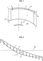
- the rotational movement R of the motor rotating the blade 2 with the association of various external elements such as for example the ingestion of birds, or vibratory phenomena, can induce sudden and significant contacts between the blade head 27 and the abradable 301 located on the casing 300 of the fan, as shown in FIG. Figure 1 .
- the radial clearance J at the head of the fan 280 and the volume of the blade 2 are sized so as to avoid the latter engaging in the abradable material to the point of damaging the engine.
- the blade In a first case, if this deformation induces an increase in clearance so as to reduce the forces and disengage the blade from the abradable material, the blade is defined as non-self-engaging. It is then considered that in this first case the behavior of the blade is healthy when it comes into contact with the abradable material.
- the blade is defined as self-engaging.
- the blade will continue to sink into the abradable and the forces on the blade will increase. The blade and the surrounding parts of it can then suffer serious damage.
- the simplest solution to avoid this self-engagement phenomenon or at least reduce its criticality is to increase the clearance at the blade tip in order to have an additional margin before the blade contacts the abradable. This strategy avoids any damage to the engine but can have a significant impact on the aerodynamic performance of the blade. Increasing the clearance at the tip increases the leakage flow and the associated losses in this area.
- a first objective of the invention is to obtain a rotating turbomachine fan blade, making it possible to limit the criticality of self-engagement on the leading edge of the blade head without deteriorating the aerodynamic performance.
- a second objective of the invention is to obtain a rotating turbomachine fan blade, making it possible to avoid configurations of the leading edge of the blade head which, in the event of self-engagement, are difficult to detach due to their geometric profile and increase the criticality of self-engagement.
- the prescribed wear metal projection provided at the metal blade head can be sufficient to prevent self-engagement of the entire blade from its leading edge.
- the wear of the prescribed wear metal projection of the blade head during of its possible rotation against the abradable material of the fan casing can be progressive to maintain a sufficient height of the blade tip reducing the leakage flow between the blade and this casing, while avoiding the self-engagement of the second case mentioned above.
- the prescribed breakage projection or fusible zone on a self-engaging blade allows, during contact, to disengage the blade, thus limiting damage to the blade tip. Thus, rather than changing many parts during a critical event leading to a phenomenon of self-engagement of the blade, only the blade can be repaired or replaced.
- the determination of the clearances at the blade tip no longer takes into account the self-engaging nature of a blade. It is then possible to reduce the clearances, which improves the aerodynamic performance of the blade.
- the sizing of a blade according to the engine target (diameter, rotation speed, etc.) will determine the optimal solution to achieve the prescribed rupture zone among the proposed embodiments.
- the longitudinally tapered thickness of the prescribed wear metal projection is constant at least over a portion of the determined non-zero height.
- the metal blade head portion has a thickness increasing in a direction from upstream to downstream, the at least one recess is delimited by edges of the metal upstream nose, the thickness occupied by the at least one recess relative to the edges increasing in the direction from upstream to downstream over a major part of a length of the metal upstream nose.
- the metal part of the blade head has a thickness increasing in a direction going from upstream to downstream, the at least one recess is delimited by edges of the metal upstream nose, said determined non-zero height, occupied by the at least one recess relative to the edges, decreasing in a direction going from upstream to downstream over a major part of a length of the metal upstream nose.
- the at least one recess is formed by at least one shoulder, which is connected to the first extrados flank of the metal upstream nose.
- the shoulder may incorporate a curve.
- the at least one recess is formed by a shoulder, which is connected to the second intrados flank of the metal upstream nose.
- the shoulder may incorporate a curve.
- the metal upstream nose comprises as a recess at least a first recess, which is formed by a first shoulder connected to the first extrados flank of the metal upstream nose, and at least a second recess, which is formed by a second shoulder connected to the second intrados flank of the metal upstream nose.
- the shoulder may include a curve.
- the shoulder is curved.
- the prescribed wear metal projection surrounds the at least one recess.
- the blade tip edge has a further prescribed wear projection, which is of longitudinally tapered thickness and which extends the prescribed metal wear projection.
- the further prescribed wear projection on the blade tip edge of the blade body is an additional projection supplementing the first projection of the metal reinforcing piece in its extension in the first longitudinal direction.
- a second subject of the invention is a rotary turbomachine fan, comprising a longitudinal rotary fan hub and a plurality of blades as described above, which are fixed at their blade root to the longitudinal rotary fan hub.
- a third object of the invention is a turbomachine comprising a rotary fan as described above, and, downstream of the fan, a low pressure compressor, a high pressure compressor, a combustion chamber, a high pressure turbine and a low pressure turbine.
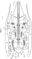
- turbomachine 1 shown in the Figure 3 is intended to be installed on an aircraft not shown to propel it into the air.
- the gas turbine engine or turbomachine assembly 1 extends around an axis AX or axial direction AX (or first longitudinal direction AX mentioned below) oriented from upstream to downstream. Subsequently, the terms “upstream”, respectively “downstream” or “front”, respectively “rear”, or “left” respectively “right” or “axially” are taken along the general direction of the gases flowing in the turbomachine along the axis AX.
- the direction from the inside to the outside is the radial direction DR (or third height direction DR mentioned below) starting from the axis AX.
- the turbomachine 1 is for example a double-spool one.
- the turbomachine 1 comprises a first stage formed by a rotary fan 280 and a central gas turbine engine 130, located downstream of the rotary fan 280.
- the gas generator 130 comprises, from upstream to downstream in the direction of gas flow, a low-pressure compressor CBP1, a high-pressure compressor CHP1, a combustion chamber 160, a high-pressure turbine THP1 and a low-pressure turbine TBP1, which delimit a primary gas flow FP1.
- the rotary fan 280 includes a set of rotating fan blades 2 extending radially outwardly from a rotating fan hub 250.
- the rotating fan blades 2 are externally surrounded by a fan housing 300, having one or more layers 301 of an abradable material on its surface opposite the blade tips 27 of the blades 2.
- the turbomachine 1 has an upstream intake end 290 located upstream of the fan 280, and a downstream exhaust end 310.
- the turbomachine 1 also comprises an inter-vein casing 360 which delimits a primary vein in which circulates the primary flow FP1 which passes downstream of the fan 280 through the low pressure compressor CBP1, the high pressure compressor CHP1, the high pressure turbine THP1 and the low pressure turbine TBP1.
- the inter-vein casing 360 comprises, from upstream to downstream, a casing 361 of the low pressure compressor CBP1, an intermediate casing 260, which is interposed between the low pressure compressor CBP1 and the high pressure compressor CHP1, a casing 362 of the high pressure compressor CHP1, a casing 363 of the high pressure turbine THP1 and a casing 190 of the low pressure turbine TBP1.
- the CBP1 low pressure compressor and the CHP1 high pressure compressor may each comprise one or more stages, each stage being formed by a set of fixed blades (or stator blades) and a set of rotating blades (or rotor blades).
- the fixed blades 101 of the low pressure compressor CBP1 are fixed to the casing 361.
- the rotary blades 102 of the low pressure compressor CBP1 are fixed to a first rotary transmission shaft 410.
- the fixed blades 103 of the high pressure compressor CHP1 are fixed to the casing 362.
- the rotary blades 104 of the high pressure compressor CHP1 are fixed to a second rotary transmission shaft 400.
- the THP1 high pressure turbine and the TBP1 low pressure turbine can each comprise one or more stages, each stage being formed by a set of fixed blades (or stator blades) and a set of rotating blades (or rotor blades).
- the fixed blades 105 of the high pressure turbine THP1 are fixed to the casing 363.
- the rotating blades 106 of the high pressure turbine THP1 are fixed to the second rotating transmission shaft 400.
- the fixed blades 107 of the low pressure turbine TBP1 are fixed to the casing 190.
- the rotating blades 108 of the low pressure turbine TBP1 are fixed to the first rotating transmission shaft 410.
- the rotating blades 108 of the low-pressure turbine TBP1 drive the rotating blades 102 of the low-pressure compressor CBP1 to rotate about the axis AX under the effect of the thrust of the gases coming from the combustion chamber 160.
- the rotating blades 106 of the high-pressure turbine THP1 drive the rotating blades 104 of the high-pressure compressor CHP1 to rotate about the axis AX under the effect of the thrust of the gases coming from the combustion chamber 160.
- the rotary fan blades 2 are upstream of the blades 101, 102, 103, 104, 105, 106, 107 and 108 and are of a different shape from them.
- turbomachine 1 In operation, air flows through the rotary fan 280 and a first portion FP1 (primary flow FP1) of the airflow is routed through the low-pressure compressor CBP1 and the high-pressure compressor CHP1, in which the airflow is compressed and sent to the combustion chamber 160.
- the hot combustion products (not shown in the figures) from the combustion chamber 160 are used to drive the turbines THP1 and TBP1 and thus produce the thrust of the turbomachine 1.
- the turbomachine 1 also includes a secondary vein 390 which is used to pass a secondary flow FS1 of the airflow discharged from the rotary fan 280 around the inter-vein casing 360.
- the secondary vein 390 extends between an inner wall 201 of a fairing 200 or nacelle 200 and the inter-vein casing 360 surrounding the engine with central gas turbine 130, the fan casing 300 being the upstream part of this fairing 200 or nacelle 200.
- Arms 340 connect the intermediate casing 260 to the internal wall 201 of the fairing 200 in the secondary vein 390 of the secondary flow FS1.
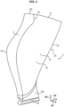
- the blade 2 comprises a body 20 made of a composite material, which extends between an upstream edge 22 and a downstream edge 23 distant from the upstream edge in the first longitudinal direction AX.
- the body 20 has a three-dimensional curvature in several plane sections taken perpendicular to the first longitudinal direction AX.
- the body 20 made of composite material extends between an extrados 24 and a intrados 25, distant from the extrados 25 along the second direction EP of thickness transverse to the first direction AX.
- the extrados 24 is turned outwards in the direction of rotation of the fan blade 2 when the fan hub 250 to which the blade root 26 is fixed rotates about the axial direction AX.
- the body 20 has a three-dimensional curvature in several plan sections taken perpendicular to the second direction EP of thickness.
- the extrados 24 is asymmetrical relative to the intrados 25.
- the body 20 made of composite material extends between a blade root 26 and the upper edge 27 of the blade head of the body 20, distant from the blade root 26 along the third height direction DR, transverse to the first and second directions AX and EP.
- the third height direction DR is oriented from bottom to top from the blade root 26 to the upper edge 27 of the blade head and to the metal part 27b of the blade head described below.
- the blade root 26 is used to be fixed to the longitudinal rotating hub 250 of the fan.
- the blade root 26 may have a thickened cross-section, which may for example be in the shape of a dovetail or the like, along the direction EP relative to an intermediate zone 26b located between the blade root 26 and the upper edge 27 of the blade head.
- the blade root 26 can thus be inserted into a peripheral housing of the fan hub 250 to be fixed there.
- the body 20 of the blade 2 is made of a composite material woven three-dimensionally in a resin.
- the body 20 made of composite material comprises a resin matrix in which is embedded a fibrous reinforcement 4 comprising warp strands extending at least in the third height direction DR and weft strands extending at least in the first longitudinal direction AX in the finished state of the blade 2.
- a possible manufacturing method of the body 20 of the blade 2 is as follows. The warp strands are woven three-dimensionally with the weft strands to form the fibrous reinforcement during a first weaving step.
- the fiber reinforcement is placed in a mold, where the fiber reinforcement is deformed according to a three-dimensional curvature imposed by a prescribed three-dimensional curvature of the interior walls of the mold, then resin is injected around the fiber reinforcement in the mold, to give the three-dimensional shape of the body 20 of the blade 2 in the finished state.
- the warp strands and the weft strands have the three-dimensional curvature of the body 20 in the finished state.
- the fiber reinforcement 4 may be formed from a single-piece fiber preform obtained by three-dimensional or multi-layer weaving with varying thickness.
- warp and weft strands which may in particular comprise carbon, glass, basalt, and/or aramid fibers.
- the matrix is typically a polymer matrix, for example epoxy, bismaleimide, or polyimide.
- the blade may be formed by molding using a vacuum resin injection process of the RTM (Resin Transfer Molding) type, or VARRTM (Vacuum Resin Transfer Molding).
- RTM Resin Transfer Molding
- VARRTM Vauum Resin Transfer Molding
- three-dimensional weaving it is understood that the warp strands follow sinuous paths in order to link together weft strands belonging to different weft strand layers except for delinks, it being noted that a three-dimensional weave, in particular an interlock weave, may include two-dimensional surface weaves. Different three-dimensional weave weaves may be used, such as interlock, multi-satin or multi-voile weaves.
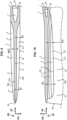
- Upstream of the upstream edge 22 is fixed, for example by gluing using a layer 7 of adhesive, a metal reinforcement part 3 (also called a shield) forming a leading edge 30 of the blade 2 ( Figure 4 ).
- the reinforcement part 3 has the function of facing the aerodynamic flow entering in flight to address the problem of blade erosion and protection of the blade against bird ingestion.
- a metal part 27b of the blade head of the metal reinforcement part 3 is described below with reference to figures 5 to 17 .
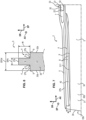
- the metal reinforcement part 3 comprises a metal upstream nose 31, which forms the leading edge 30 of the blade 2 and which is fixed to the upstream edge 22.
- the metal upstream nose 31 is formed of a first extrados flank 32b and a second intrados flank 33b, which connect to each other in the direction of the thickness direction EP and which end upstream at the leading edge 30.
- the metal reinforcement part 3 comprises a first fin 32, which is connected downstream of the first extrados flank 32b and which is fixed by the layer 7 of adhesive to an upstream part 28 of the extrados 24 of the body 2.
- the metal reinforcement part 3 comprises a second fin 33, which is connected downstream of the second intrados flank 33b and which is bonded by the layer 7 of adhesive to an upstream part 29 of the intrados 25 of the body 2.
- the metal upstream nose 31, the first fin 32 and the second fin 33 delimit a cavity in which the upstream edge 22 and the upstream parts 28, 29 of the extrados 24 and the intrados 25 are located.
- the metal upstream nose 31 is solid and is thicker than each fin 32 and 33 in the main zone 34 of part 3.
- the body 20, the metal upstream nose 31, the first fin 32 and the second fin 33 have a three-dimensional curvature in first sections taken in several distinct planes perpendicular to the first direction AX, in second sections taken in several distinct planes perpendicular to the second direction EP and in third sections taken in several distinct planes perpendicular to the third direction DR.
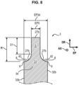
- the part 3 ends along the third direction DE of height above its main zone 34 by a metal part 27b of blade head, located upstream of the first edge 27 of blade head of the body 2 made of composite material.
- the upstream metal nose 31 comprises on the metal part 27b of the blade head one or more metal projection(s) 5 of prescribed wear.
- Each metal projection 5 of prescribed wear has a tapered thickness EP5 in the first longitudinal direction AX and a determined non-zero height H in the third height direction DR.
- the metal projection(s) 5 of prescribed wear is delimited by one or more recesses 4, which is/are of tapered thickness in the first longitudinal direction AX and which are arranged at least on the metal part 27b of the blade head of the upstream metal nose 31.
- the metal projection(s) 5 of prescribed wear is configured to detach at least partially in the presence of tangential friction going in the second thickness direction EP against the metal part 27b of the blade head.
- the recess(es) 4 and the prescribed wear metal protrusion(s) 5 extend upstream the first metal fin 32 and/or the second metal fin 33 and/or the upstream edge 22 of the body 21 made of composite material.
- the protrusion 5 thus acts as a fuse in the event of excessive contact with the abradable material 301 located on the casing 300 of the fan 280.
- the prescribed breakage protrusion 5 is present in a self-engaging part of the blade 2, that is to say a part that can come into contact with the abradable material 301 of the casing 300 of the fan 280, as defined above.
- the projection 5 will partially detach from the blade, which makes it possible to directly exit contact with the abradable 301 and will avoid self-engagement.
- the dimensions of the projection 5 can be determined based on the dimensions of the parts of the blade closest to the abradable 301.
- the projection 5 forms a thinning of the metal part 27b of the blade head.
- the recess(es) 4 has the determined non-zero height H above the main part 34 and is delimited downwards by a transition surface 8 connecting the projection 5 to the main part 34 of thickness EP34 greater than the thickness EP5 of the projection 5.
- the transition surface 8 faces upwards in the third height direction DR and may have, for example, a break 9 in slope or edge 9 connecting it to the main part 34 and/or to the projection 5.
- the longitudinally tapered thickness EP5 of the prescribed wear metal projection 5 is constant at least over a portion of the determined height H from the top.
- this portion of the height of the prescribed wear metal projection 5 does not offer increasing resistance during friction against the abradable material 301 of the fan casing 300 in the event of the start of self-engagement during rotation of the blade 2 and wears more easily, which reduces the risks of self-engagement and makes it possible to achieve the second objective indicated above.
- the longitudinally tapered thickness EP5 of the prescribed wear metal projection 5 is constant over the entire determined height H.
- the transition surface 8 may be flat and for example perpendicular to the projection 5.
- the longitudinally tapered thickness EP5 of the prescribed wear metal projection 5 is constant over an upper part 51 of the height H.
- the transition surface 8 may be curved (e.g. concave) in several plane sections, which are taken perpendicular to the first longitudinal direction AX as to the figures 7 to 10
- the transition surface 8 may form a fillet 42 and/or 43 or a shoulder 42 and/or 43 facing upwards.
- a first recess 4 may thus be provided, formed by a first curved shoulder 42 connected to the first extrados flank 32b of the upstream metal nose 31 and/or a second recess 4 formed by a second curved shoulder 43 connected to the second intrados flank 33b of the upstream metal nose 31.
- the projection 5 may be located on the side of the first extrados flank 32b of the upstream metal nose 31, the recess 4 being in this case on the side of the second intrados flank 33b of the upstream metal nose 31. In other embodiments not shown, the projection 5 may be located on the side of the second intrados flank 33b of the upstream metal nose 31, the recess 4 being in this case on the side of the first extrados flank 32b of the upstream metal nose 31.
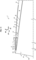
- the longitudinally tapered thickness EP5 of the prescribed wear metal projection 5 is constant over a major portion 311 of a length of the metal upstream nose 31 in the longitudinal direction AX.
- the major portion 311 of the length of the metal upstream nose 31 in the longitudinal direction AX represents at least 50% of the length of the metal upstream nose 31 in the longitudinal direction AX.
- the length of the metal upstream nose 31 in the longitudinal direction AX is taken between the leading edge 30 and the upstream edge 22, or between the leading edge 30 and the first metal fin 32, or between the leading edge 30 and the second metal fin 33.
- the metal part 27b of the blade head and/or the prescribed metal wear projection 5 has the thickness EP5 increasing in the direction from upstream to downstream along the longitudinal direction AX.
- the recess(es) 4 is delimited by the edges 9 of the metal upstream nose 31.
- the thickness e1, e2 occupied by the at least one recess 4 relative to the edges 9 increases in the direction from upstream to downstream along the longitudinal direction AX over a major part 311 of the length of the metal upstream nose 31.
- the major part 311 can have the definition mentioned above.
- the first edge 27 of the blade head of the body 2 made of composite material may have another thickness increasing in the direction from upstream to downstream along the longitudinal direction AX over an upstream portion, for example over at least 20% or at least 50% starting from the upstream edge 22, of the length of this first edge 27 of the blade head, taken along the longitudinal direction AX.
- the length of this first edge 27 of the blade head may be taken along the longitudinal direction AX between the upstream edge 22 and the downstream edge 23 of the body 20 made of composite material.
- the determined non-zero height H, h1, h2 occupied by the recess(es) 4 and by the projection 5 relative to the edges 9 decreases in the direction going from upstream to downstream following the longitudinal direction AX over a major part 311 of the length of the upstream metal nose 31.
- the major part 311 can have the definition mentioned above.
- the prescribed wear metal projection 5 surrounds the recess(es) 4.
- the projection 5 comprises two first and second longitudinally tapered parts 51 and 52, which extend in the DR direction of the height respectively the first extrados flank 32b of the upstream metal nose 31 and the second intrados flank 33b of the upstream metal nose 31.
- the recess 4 is delimited between the longitudinally tapered parts 51 and 52 and above a bottom 40 located between these longitudinally tapered parts 51 and 52. This makes it possible to maintain the aerodynamic profile of the blade, the external surfaces being unchanged.
- the recess 4 may be a hollow, which can be produced by machining.
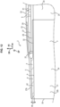
- the blade head edge 27 has another prescribed wear projection 6 (or second wear projection 6 prescribed), which is of tapered thickness along the longitudinal direction AX and which extends downstream the prescribed wear metal projection 5 (or first prescribed wear metal projection 5) along the longitudinal direction AX.
- the other prescribed wear projection 6 is therefore made of the composite material of the body 20 of the blade 2.
- the other projection 6 forms a thinning of the blade tip edge 27.
- the other projection 6 thus acts as a fuse in the event of excessive contact with the abradable 301 located on the casing 300 of the fan 280.
- the other prescribed breakage projection 6 is present in a self-engaging part of the blade 2, that is to say a part which can come into contact with the abradable material 301 of the casing 300 of the fan 280, as defined above.
- the other projection 6 will partially detach from the blade, which makes it possible to directly exit contact with the abradable 301 and will avoid self-engagement.
- the dimensions of the other projection 6 can be determined based on the dimensions of the parts of the blade closest to the abradable 301.
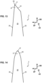
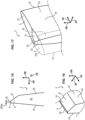
- the other prescribed wear projection 6 may be bordered by a chamfer 61 extending in the longitudinal direction AX and connected to the intrados 25 (or to the extrados 24 in other embodiments not shown), as illustrated in figures 12 , 13 and 14 at 17.
- Chamfer 61 can be flat.
- the other 6 may end upwards with a flat surface 62, which is tapered along the longitudinal direction AX and which has a non-zero thickness EP62 as shown in figures 12 And 15 to 17 .
- the chamfer 61 may extend over a portion of the length of the edge 27 of the blade head starting from its upstream edge 22, as shown in Figure 17 (where the adhesive layer 7 has not been shown), to form a local chamfer 61.
- the other 6 may end upwards with a rounded edge 64, which extends in the longitudinal direction AX and which is connected to the intrados 25 and to the extrados 24, as shown in Figure 14
- the rounded edge 64 has in several distinct planes transverse to the AX direction a radius of curvature less than that of the intrados 25 and the extrados 24.
Landscapes
- Engineering & Computer Science (AREA)
- Mechanical Engineering (AREA)
- General Engineering & Computer Science (AREA)
- Chemical & Material Sciences (AREA)
- Materials Engineering (AREA)
- Composite Materials (AREA)
- Architecture (AREA)
- Structures Of Non-Positive Displacement Pumps (AREA)
- Turbine Rotor Nozzle Sealing (AREA)
Claims (13)
- Rotationsgebläse-Laufschaufel (2) einer Turbomaschine, wobei die Laufschaufel (2) umfasst:einen Körper (20) aus einem Verbundmaterial, der eine stromaufwärtige Kante (22) und eine stromabwärtige Kante (23), zwischen denen sich der Körper (20) entlang einer ersten Längsrichtung (AX) erstreckt, eine Saugseite (24) und eine Druckseite (25), zwischen denen sich der Körper (20) entlang einer zweiten Dickenrichtung (EP), die zu der ersten Richtung (AX) quer liegt, erstreckt, einen Laufschaufelfuß (26) und eine Laufschaufelkopfkante (27), zwischen denen sich der Körper (20) entlang einer dritten Höhenrichtung (DR), die zu der ersten und der zweiten Richtung (AX, EP) quer liegt, erstreckt, aufweist, wobei der Laufschaufelfuß (26) die Funktion der Befestigung an einer Längsdrehnabe (250) des Gebläses erfüllt,ein metallisches Verstärkungsstück (3), das eine metallische stromaufwärtige Nase (31), die eine Vorderkante (30) der Laufschaufel bildet und die an der stromaufwärtigen Kante (22) befestigt ist, eine erste metallische Rippe (32), die stromabwärts einer ersten Saugseitenflanke (32b) der metallischen stromaufwärtigen Nase (31) verbunden ist und die an einem stromaufwärtigen Teil (28) der Saugseite (24) befestigt ist, und eine zweite metallische Rippe (33), die stromabwärts einer zweiten Druckseitenflanke (33b) der metallischen stromaufwärtigen Nase (31) verbunden ist und die an einem stromaufwärtigen Teil (29) der Druckseite (25) befestigt ist, umfasst, wobei die metallische stromaufwärtige Nase (31) einen metallischen Laufschaufelkopfteil (27b) aufweist, der sich stromaufwärts der Laufschaufelkopfkante (27) befindet,wobei die metallische stromaufwärtige Nase (31) mindestens auf dem metallischen Laufschaufelkopfteil (27b) mindestens eine Aussparung (4) umfasst, deren Dicke sich längsseitig (AX) verjüngt und die entlang der dritten Höhenrichtung (DR) auf den metallischen Laufschaufelkopfteil (27b) mündet,wobei die Laufschaufel dadurch gekennzeichnet ist, dassdie mindestens eine Aussparung (4) auf dem metallischen Laufschaufelkopfteil (27b) über eine bestimmte Höhe (H) ungleich null entlang der dritten Höhenrichtung (DR) mindestens einen vorgeschriebenen metallischen Verschleißvorsprung (5) begrenzt, der eine sich längsseitig (AX) verjüngende Dicke (EP5) auf einem Großteil (311) einer Länge der metallischen stromaufwärtigen Nase (31) entlang der ersten Längsrichtung (AX) aufweist, und der dazu konfiguriert ist, sich bei Vorliegen einer tangentialen Reibung, die in der zweiten Dickenrichtung (EP) gegen den metallischen Laufschaufelkopfteil (27b) geht, mindestens teilweise zu lösen,wobei die mindestens eine Aussparung (4) und der mindestens eine vorgeschriebene metallische Verschleißvorsprung (5) in der ersten Längsrichtung (AX) nach stromaufwärts die erste metallische Rippe (32) und/oder die zweite metallische Rippe (33) und/oder die stromaufwärtige Kante (22) des Körpers (20) aus Verbundmaterial verlängern.
- Laufschaufel nach Anspruch 1, dadurch gekennzeichnet, dass die sich längsseitig (AX) verjüngende Dicke (EP5) des vorgeschriebenen metallischen Verschleißvorsprungs (5) mindestens auf einem Teil (51, H) der bestimmten Höhe (H) ungleich null konstant ist.
- Laufschaufel nach Anspruch 1, dadurch gekennzeichnet, dass die sich längsseitig (AX) verjüngende Dicke (EP5) des vorgeschriebenen metallischen Verschleißvorsprungs (5) auf dem Großteil (311) der Länge der metallischen stromaufwärtigen Nase (31) konstant ist.
- Laufschaufel nach einem beliebigen der vorhergehenden Ansprüche, dadurch gekennzeichnet, dass der metallische Laufschaufelkopfteil (27b) eine Dicke (EP5) aufweist, die in einer Richtung von stromaufwärts nach stromabwärts zunimmt, die mindestens eine Aussparung (4) durch Stege (9) der metallischen stromaufwärtigen Nase (31) begrenzt ist, wobei die Dicke (e1, e2), die von der mindestens einen Aussparung (4) im Verhältnis zu den Stegen (9) eingenommen wird, in der Richtung von stromaufwärts nach stromabwärts auf dem Großteil (311) der Länge der metallischen stromaufwärtigen Nase (31) zunimmt.
- Laufschaufel nach einem beliebigen der vorhergehenden Ansprüche, dadurch gekennzeichnet, dass der metallische Laufschaufelkopfteil (27b) eine Dicke aufweist, die in einer Richtung von stromaufwärts nach stromabwärts zunimmt, die mindestens eine Aussparung (4) durch Stege (9) der metallischen stromaufwärtigen Nase (31) begrenzt ist, wobei die bestimmte Höhe (H, h1, h2) ungleich null, die von der mindestens einen Aussparung (4) im Verhältnis zu den Stegen (9) eingenommen wird, in einer Richtung von stromaufwärts nach stromabwärts auf dem Großteil (311) der Länge der metallischen stromaufwärtigen Nase (31) abnimmt.
- Laufschaufel nach einem beliebigen der vorhergehenden Ansprüche, dadurch gekennzeichnet, dass die mindestens eine Aussparung (4) durch mindestens eine Schulter (42) gebildet wird, die mit der ersten Saugseitenflanke (32b) der metallischen stromaufwärtigen Nase (31) verbunden ist.
- Laufschaufel nach einem beliebigen der vorhergehenden Ansprüche, dadurch gekennzeichnet, dass die mindestens eine Aussparung (4) durch eine Schulter (43) gebildet wird, die mit der zweiten Druckseitenflanke (33b) der metallischen stromaufwärtigen Nase (31) verbunden ist.
- Laufschaufel nach einem beliebigen der Ansprüche 1 bis 5, dadurch gekennzeichnet, dass die metallische stromaufwärtige Nase (31) als Aussparung (4) mindestens eine erste Aussparung (42), die von einer ersten Schulter (42) gebildet wird, die mit der ersten Saugseitenflanke (32b) der metallischen stromaufwärtigen Nase (31) verbunden ist, und mindestens eine zweite Aussparung (43), die durch eine zweite Schulter gebildet wird, die mit der zweiten Druckseitenflanke (33b) der metallischen stromaufwärtigen Nase (31) verbunden ist, umfasst.
- Laufschaufel nach einem beliebigen der Ansprüche 6 bis 8, dadurch gekennzeichnet, dass die Schulter (42, 43) gekrümmt ist.
- Laufschaufel nach einem beliebigen der Ansprüche 1 bis 5, dadurch gekennzeichnet, dass der vorgeschriebene metallische Verschleißvorsprung (5) die mindestens eine Aussparung (4) umgibt.
- Laufschaufel nach einem beliebigen der Ansprüche 1 bis 5, dadurch gekennzeichnet, dass die Laufschaufelkopfkante (27)einen anderen vorgeschriebenen Verschleißvorsprung (6) umfasst, der eine sich längsseitig (AX) verjüngende Dicke aufweist und der den vorgeschriebenen metallischen Verschleißvorsprung (5) verlängert.
- Rotationsgebläse (280) einer Turbomaschine, umfassend eine Längsdrehnabe (250) und eine Vielzahl von Laufschaufeln (2) nach einem beliebigen der vorhergehenden Ansprüche, die an ihrem Laufschaufelfuß (26) an der Längsdrehnabe (250) befestigt sind.
- Turbomaschine (1), umfassend ein Rotationsgebläse (280) nach Anspruch 12, und stromabwärts des Gebläses (280) einen Niederdruck-Verdichter (CBP1), einen Hochdruck-Verdichter (CHP1), eine Brennkammer (160), eine Hochdruckturbine (THP1) und eine Niederdruckturbine (TBP1).
Applications Claiming Priority (2)
| Application Number | Priority Date | Filing Date | Title |
|---|---|---|---|
| FR2002990A FR3108662B1 (fr) | 2020-03-26 | 2020-03-26 | Aube de soufflante rotative de turbomachine, soufflante et turbomachine munies de celle-ci |
| PCT/FR2021/050500 WO2021191559A1 (fr) | 2020-03-26 | 2021-03-24 | Aube de soufflante rotative de turbomachine, soufflante et turbomachine munies de celle-ci |
Publications (2)
| Publication Number | Publication Date |
|---|---|
| EP4127409A1 EP4127409A1 (de) | 2023-02-08 |
| EP4127409B1 true EP4127409B1 (de) | 2025-04-23 |
Family
ID=70614276
Family Applications (1)
| Application Number | Title | Priority Date | Filing Date |
|---|---|---|---|
| EP21732359.1A Active EP4127409B1 (de) | 2020-03-26 | 2021-03-24 | Turbomaschinen-bläserlaufschaufel, bläser und turbomaschine mit einer solchen schaufel |
Country Status (5)
| Country | Link |
|---|---|
| US (1) | US11920494B2 (de) |
| EP (1) | EP4127409B1 (de) |
| CN (1) | CN115461525B (de) |
| FR (1) | FR3108662B1 (de) |
| WO (1) | WO2021191559A1 (de) |
Families Citing this family (1)
| Publication number | Priority date | Publication date | Assignee | Title |
|---|---|---|---|---|
| FR3115079B1 (fr) * | 2020-10-12 | 2022-10-14 | Safran Aircraft Engines | Aube en materiau composite comprenant un bouclier de bord d’attaque, turbomachine comprenant l’aube |
Family Cites Families (12)
| Publication number | Priority date | Publication date | Assignee | Title |
|---|---|---|---|---|
| GB1107024A (en) | 1965-11-04 | 1968-03-20 | Parsons C A & Co Ltd | Improvements in and relating to blades for turbo-machines |
| FR2832191B1 (fr) | 2001-11-14 | 2004-10-08 | Snecma Moteurs | Aube de soufflante a sommet fragilise |
| GB0216952D0 (en) * | 2002-07-20 | 2002-08-28 | Rolls Royce Plc | Gas turbine engine casing and rotor blade arrangement |
| FR2906320B1 (fr) | 2006-09-26 | 2008-12-26 | Snecma Sa | Aube composite de turbomachine a renfort metallique |
| US7780410B2 (en) * | 2006-12-27 | 2010-08-24 | General Electric Company | Method and apparatus for gas turbine engines |
| US8016562B2 (en) * | 2007-11-20 | 2011-09-13 | Siemens Energy, Inc. | Turbine blade tip cooling system |
| US8790088B2 (en) * | 2011-04-20 | 2014-07-29 | General Electric Company | Compressor having blade tip features |
| US10107136B2 (en) | 2014-12-19 | 2018-10-23 | Rolls-Royce Plc | Blade |
| EP3034785B1 (de) | 2014-12-19 | 2019-01-30 | Rolls-Royce plc | Eine gasturbinen gebläseschaufel mit variabler bruchbeständigkeit |
| CA2972764A1 (en) | 2015-01-13 | 2016-07-21 | General Electric Company | A composite airfoil with fuse architecture |
| FR3043714B1 (fr) * | 2015-11-16 | 2017-12-22 | Snecma | Partie avant de turbomachine d'aeronef comprenant une soufflante unique entrainee par un reducteur, ainsi que des aubes directrices de sortie structurales agencees en partie en amont d'un bec de separation |
| US10815798B2 (en) * | 2018-02-08 | 2020-10-27 | General Electric Company | Turbine engine blade with leading edge strip |
-
2020
- 2020-03-26 FR FR2002990A patent/FR3108662B1/fr active Active
-
2021
- 2021-03-24 EP EP21732359.1A patent/EP4127409B1/de active Active
- 2021-03-24 WO PCT/FR2021/050500 patent/WO2021191559A1/fr not_active Ceased
- 2021-03-24 CN CN202180030967.2A patent/CN115461525B/zh active Active
- 2021-03-24 US US17/913,946 patent/US11920494B2/en active Active
Also Published As
| Publication number | Publication date |
|---|---|
| FR3108662A1 (fr) | 2021-10-01 |
| US20230129130A1 (en) | 2023-04-27 |
| WO2021191559A1 (fr) | 2021-09-30 |
| CN115461525A (zh) | 2022-12-09 |
| US11920494B2 (en) | 2024-03-05 |
| EP4127409A1 (de) | 2023-02-08 |
| CN115461525B (zh) | 2025-08-01 |
| FR3108662B1 (fr) | 2022-12-02 |
Similar Documents
| Publication | Publication Date | Title |
|---|---|---|
| EP2896790B1 (de) | Gebläseschaufel mit einer abdeckung mit abgeschrägten kanten | |
| WO2022208002A1 (fr) | Aube comprenant une structure en matériau composite et procédé de fabrication associé | |
| EP4093670B1 (de) | Schaufel mit verbundwerkstoffstruktur und zugehöriges herstellungsverfahren | |
| EP4115053B1 (de) | Fanschaufel mit einem einsatz aus steifen fasern | |
| EP3990752B1 (de) | Zwischenschaufelplattform mit einem opfer-kastenabschnitt | |
| EP3121375A1 (de) | Verbundwerkstoffschaufel eines kompressors eines axialen turbotriebwerks | |
| EP4117895A1 (de) | Schaufel mit einer struktur aus verbundstoff und zugehöriges herstellungsverfahren | |
| EP3996990B1 (de) | Propellerblatt | |
| EP4062034B1 (de) | Turbofanlaufschaufel, turbofan und damit versehene turbomaschine | |
| EP4127409B1 (de) | Turbomaschinen-bläserlaufschaufel, bläser und turbomaschine mit einer solchen schaufel | |
| FR3087831A1 (fr) | Aube comprenant une structure en materiau composite et une piece de raidissement metallique | |
| FR3116089A1 (fr) | Aube de soufflante rotative de turbomachine, soufflante et turbomachine munies de celle-ci | |
| FR3108663A1 (fr) | Aube de soufflante rotative de turbomachine, soufflante et turbomachine munies de celle-ci | |
| FR3108665A1 (fr) | Rotor de soufflante comprenant des aubes à centre de gravité en amont | |
| EP4115055B1 (de) | Fertigungsverfahren einer platform in verbundbauweise für den bläser eines flugzeugtriebwerks | |
| FR3158536A1 (fr) | Aube comportant un corps metallique et un noyau non metallique et procédé de fabrication d’une telle aube | |
| FR3158537A1 (fr) | Aube composite de turbomachine comprenant un pied d’aube monolithique | |
| FR3141966A1 (fr) | Elément de Rotor pour turbomachine à aubes composites liées à un disque métallique | |
| FR3158538A1 (fr) | Aube comportant un corps metallique et une enveloppe externe recouvrant une structure ajouree et/ou en treillis du corps metallique | |
| FR3136011A1 (fr) | Aube comprenant une structure en matériau composite et procédé de fabrication associé | |
| FR3152039A1 (fr) | aube de turbomachine monobloc | |
| FR3108664A1 (fr) | Rotor de soufflante comprenant des aubes à centre de gravité en amont |
Legal Events
| Date | Code | Title | Description |
|---|---|---|---|
| STAA | Information on the status of an ep patent application or granted ep patent |
Free format text: STATUS: UNKNOWN |
|
| STAA | Information on the status of an ep patent application or granted ep patent |
Free format text: STATUS: THE INTERNATIONAL PUBLICATION HAS BEEN MADE |
|
| PUAI | Public reference made under article 153(3) epc to a published international application that has entered the european phase |
Free format text: ORIGINAL CODE: 0009012 |
|
| STAA | Information on the status of an ep patent application or granted ep patent |
Free format text: STATUS: REQUEST FOR EXAMINATION WAS MADE |
|
| 17P | Request for examination filed |
Effective date: 20221019 |
|
| AK | Designated contracting states |
Kind code of ref document: A1 Designated state(s): AL AT BE BG CH CY CZ DE DK EE ES FI FR GB GR HR HU IE IS IT LI LT LU LV MC MK MT NL NO PL PT RO RS SE SI SK SM TR |
|
| DAV | Request for validation of the european patent (deleted) | ||
| DAX | Request for extension of the european patent (deleted) | ||
| GRAP | Despatch of communication of intention to grant a patent |
Free format text: ORIGINAL CODE: EPIDOSNIGR1 |
|
| STAA | Information on the status of an ep patent application or granted ep patent |
Free format text: STATUS: GRANT OF PATENT IS INTENDED |
|
| INTG | Intention to grant announced |
Effective date: 20250107 |
|
| GRAS | Grant fee paid |
Free format text: ORIGINAL CODE: EPIDOSNIGR3 |
|
| GRAA | (expected) grant |
Free format text: ORIGINAL CODE: 0009210 |
|
| STAA | Information on the status of an ep patent application or granted ep patent |
Free format text: STATUS: THE PATENT HAS BEEN GRANTED |
|
| AK | Designated contracting states |
Kind code of ref document: B1 Designated state(s): AL AT BE BG CH CY CZ DE DK EE ES FI FR GB GR HR HU IE IS IT LI LT LU LV MC MK MT NL NO PL PT RO RS SE SI SK SM TR |
|
| REG | Reference to a national code |
Ref country code: GB Ref legal event code: FG4D Free format text: NOT ENGLISH |
|
| REG | Reference to a national code |
Ref country code: CH Ref legal event code: EP |
|
| REG | Reference to a national code |
Ref country code: DE Ref legal event code: R096 Ref document number: 602021029612 Country of ref document: DE |
|
| REG | Reference to a national code |
Ref country code: IE Ref legal event code: FG4D Free format text: LANGUAGE OF EP DOCUMENT: FRENCH |
|
| REG | Reference to a national code |
Ref country code: NL Ref legal event code: MP Effective date: 20250423 |
|
| PG25 | Lapsed in a contracting state [announced via postgrant information from national office to epo] |
Ref country code: NL Free format text: LAPSE BECAUSE OF FAILURE TO SUBMIT A TRANSLATION OF THE DESCRIPTION OR TO PAY THE FEE WITHIN THE PRESCRIBED TIME-LIMIT Effective date: 20250423 |
|
| REG | Reference to a national code |
Ref country code: AT Ref legal event code: MK05 Ref document number: 1787932 Country of ref document: AT Kind code of ref document: T Effective date: 20250423 |
|
| PG25 | Lapsed in a contracting state [announced via postgrant information from national office to epo] |
Ref country code: FI Free format text: LAPSE BECAUSE OF FAILURE TO SUBMIT A TRANSLATION OF THE DESCRIPTION OR TO PAY THE FEE WITHIN THE PRESCRIBED TIME-LIMIT Effective date: 20250423 Ref country code: PT Free format text: LAPSE BECAUSE OF FAILURE TO SUBMIT A TRANSLATION OF THE DESCRIPTION OR TO PAY THE FEE WITHIN THE PRESCRIBED TIME-LIMIT Effective date: 20250825 Ref country code: ES Free format text: LAPSE BECAUSE OF FAILURE TO SUBMIT A TRANSLATION OF THE DESCRIPTION OR TO PAY THE FEE WITHIN THE PRESCRIBED TIME-LIMIT Effective date: 20250423 |
|
| REG | Reference to a national code |
Ref country code: LT Ref legal event code: MG9D |
|
| PG25 | Lapsed in a contracting state [announced via postgrant information from national office to epo] |
Ref country code: NO Free format text: LAPSE BECAUSE OF FAILURE TO SUBMIT A TRANSLATION OF THE DESCRIPTION OR TO PAY THE FEE WITHIN THE PRESCRIBED TIME-LIMIT Effective date: 20250723 Ref country code: GR Free format text: LAPSE BECAUSE OF FAILURE TO SUBMIT A TRANSLATION OF THE DESCRIPTION OR TO PAY THE FEE WITHIN THE PRESCRIBED TIME-LIMIT Effective date: 20250724 |
|
| PG25 | Lapsed in a contracting state [announced via postgrant information from national office to epo] |
Ref country code: PL Free format text: LAPSE BECAUSE OF FAILURE TO SUBMIT A TRANSLATION OF THE DESCRIPTION OR TO PAY THE FEE WITHIN THE PRESCRIBED TIME-LIMIT Effective date: 20250423 |
|
| PG25 | Lapsed in a contracting state [announced via postgrant information from national office to epo] |
Ref country code: BG Free format text: LAPSE BECAUSE OF FAILURE TO SUBMIT A TRANSLATION OF THE DESCRIPTION OR TO PAY THE FEE WITHIN THE PRESCRIBED TIME-LIMIT Effective date: 20250423 |
|
| PG25 | Lapsed in a contracting state [announced via postgrant information from national office to epo] |
Ref country code: HR Free format text: LAPSE BECAUSE OF FAILURE TO SUBMIT A TRANSLATION OF THE DESCRIPTION OR TO PAY THE FEE WITHIN THE PRESCRIBED TIME-LIMIT Effective date: 20250423 |
|
| PG25 | Lapsed in a contracting state [announced via postgrant information from national office to epo] |
Ref country code: AT Free format text: LAPSE BECAUSE OF FAILURE TO SUBMIT A TRANSLATION OF THE DESCRIPTION OR TO PAY THE FEE WITHIN THE PRESCRIBED TIME-LIMIT Effective date: 20250423 |
|
| PG25 | Lapsed in a contracting state [announced via postgrant information from national office to epo] |
Ref country code: RS Free format text: LAPSE BECAUSE OF FAILURE TO SUBMIT A TRANSLATION OF THE DESCRIPTION OR TO PAY THE FEE WITHIN THE PRESCRIBED TIME-LIMIT Effective date: 20250723 |
|
| PG25 | Lapsed in a contracting state [announced via postgrant information from national office to epo] |
Ref country code: IS Free format text: LAPSE BECAUSE OF FAILURE TO SUBMIT A TRANSLATION OF THE DESCRIPTION OR TO PAY THE FEE WITHIN THE PRESCRIBED TIME-LIMIT Effective date: 20250823 |
|
| PG25 | Lapsed in a contracting state [announced via postgrant information from national office to epo] |
Ref country code: LV Free format text: LAPSE BECAUSE OF FAILURE TO SUBMIT A TRANSLATION OF THE DESCRIPTION OR TO PAY THE FEE WITHIN THE PRESCRIBED TIME-LIMIT Effective date: 20250423 |