EP4126751B1 - Getränkeausgabeverbinder, getränkeherstellungsvorrichtung und verfahren zur getränkeherstellung - Google Patents
Getränkeausgabeverbinder, getränkeherstellungsvorrichtung und verfahren zur getränkeherstellung Download PDFInfo
- Publication number
- EP4126751B1 EP4126751B1 EP21713026.9A EP21713026A EP4126751B1 EP 4126751 B1 EP4126751 B1 EP 4126751B1 EP 21713026 A EP21713026 A EP 21713026A EP 4126751 B1 EP4126751 B1 EP 4126751B1
- Authority
- EP
- European Patent Office
- Prior art keywords
- beverage
- cavity
- container
- section
- needle
- Prior art date
- Legal status (The legal status is an assumption and is not a legal conclusion. Google has not performed a legal analysis and makes no representation as to the accuracy of the status listed.)
- Active
Links
Images



Classifications
-
- B—PERFORMING OPERATIONS; TRANSPORTING
- B67—OPENING, CLOSING OR CLEANING BOTTLES, JARS OR SIMILAR CONTAINERS; LIQUID HANDLING
- B67D—DISPENSING, DELIVERING OR TRANSFERRING LIQUIDS, NOT OTHERWISE PROVIDED FOR
- B67D3/00—Apparatus or devices for controlling flow of liquids under gravity from storage containers for dispensing purposes
- B67D3/0029—Apparatus or devices for controlling flow of liquids under gravity from storage containers for dispensing purposes provided with holders for bottles or similar containers
-
- B—PERFORMING OPERATIONS; TRANSPORTING
- B67—OPENING, CLOSING OR CLEANING BOTTLES, JARS OR SIMILAR CONTAINERS; LIQUID HANDLING
- B67D—DISPENSING, DELIVERING OR TRANSFERRING LIQUIDS, NOT OTHERWISE PROVIDED FOR
- B67D3/00—Apparatus or devices for controlling flow of liquids under gravity from storage containers for dispensing purposes
- B67D3/0029—Apparatus or devices for controlling flow of liquids under gravity from storage containers for dispensing purposes provided with holders for bottles or similar containers
- B67D3/0035—Apparatus or devices for controlling flow of liquids under gravity from storage containers for dispensing purposes provided with holders for bottles or similar containers the bottle or container being held upside down and not provided with a closure, e.g. a bottle screwed onto a base of a dispenser
-
- B—PERFORMING OPERATIONS; TRANSPORTING
- B67—OPENING, CLOSING OR CLEANING BOTTLES, JARS OR SIMILAR CONTAINERS; LIQUID HANDLING
- B67D—DISPENSING, DELIVERING OR TRANSFERRING LIQUIDS, NOT OTHERWISE PROVIDED FOR
- B67D1/00—Apparatus or devices for dispensing beverages on draught
- B67D1/07—Cleaning beverage-dispensing apparatus
-
- B—PERFORMING OPERATIONS; TRANSPORTING
- B67—OPENING, CLOSING OR CLEANING BOTTLES, JARS OR SIMILAR CONTAINERS; LIQUID HANDLING
- B67D—DISPENSING, DELIVERING OR TRANSFERRING LIQUIDS, NOT OTHERWISE PROVIDED FOR
- B67D1/00—Apparatus or devices for dispensing beverages on draught
- B67D1/08—Details
- B67D1/0857—Cooling arrangements
-
- B—PERFORMING OPERATIONS; TRANSPORTING
- B67—OPENING, CLOSING OR CLEANING BOTTLES, JARS OR SIMILAR CONTAINERS; LIQUID HANDLING
- B67D—DISPENSING, DELIVERING OR TRANSFERRING LIQUIDS, NOT OTHERWISE PROVIDED FOR
- B67D3/00—Apparatus or devices for controlling flow of liquids under gravity from storage containers for dispensing purposes
- B67D3/0009—Apparatus or devices for controlling flow of liquids under gravity from storage containers for dispensing purposes provided with cooling arrangements
-
- B—PERFORMING OPERATIONS; TRANSPORTING
- B67—OPENING, CLOSING OR CLEANING BOTTLES, JARS OR SIMILAR CONTAINERS; LIQUID HANDLING
- B67D—DISPENSING, DELIVERING OR TRANSFERRING LIQUIDS, NOT OTHERWISE PROVIDED FOR
- B67D3/00—Apparatus or devices for controlling flow of liquids under gravity from storage containers for dispensing purposes
- B67D3/0012—Apparatus or devices for controlling flow of liquids under gravity from storage containers for dispensing purposes provided with mixing devices
-
- B—PERFORMING OPERATIONS; TRANSPORTING
- B67—OPENING, CLOSING OR CLEANING BOTTLES, JARS OR SIMILAR CONTAINERS; LIQUID HANDLING
- B67D—DISPENSING, DELIVERING OR TRANSFERRING LIQUIDS, NOT OTHERWISE PROVIDED FOR
- B67D1/00—Apparatus or devices for dispensing beverages on draught
- B67D1/08—Details
- B67D1/0889—Supports
- B67D1/0891—Supports for the beverage container
-
- B—PERFORMING OPERATIONS; TRANSPORTING
- B67—OPENING, CLOSING OR CLEANING BOTTLES, JARS OR SIMILAR CONTAINERS; LIQUID HANDLING
- B67D—DISPENSING, DELIVERING OR TRANSFERRING LIQUIDS, NOT OTHERWISE PROVIDED FOR
- B67D1/00—Apparatus or devices for dispensing beverages on draught
- B67D2001/0095—Constructional details
-
- B—PERFORMING OPERATIONS; TRANSPORTING
- B67—OPENING, CLOSING OR CLEANING BOTTLES, JARS OR SIMILAR CONTAINERS; LIQUID HANDLING
- B67D—DISPENSING, DELIVERING OR TRANSFERRING LIQUIDS, NOT OTHERWISE PROVIDED FOR
- B67D1/00—Apparatus or devices for dispensing beverages on draught
- B67D2001/0095—Constructional details
- B67D2001/0096—Means for pressurizing liquid
- B67D2001/0097—Means for pressurizing liquid using a pump
-
- B—PERFORMING OPERATIONS; TRANSPORTING
- B67—OPENING, CLOSING OR CLEANING BOTTLES, JARS OR SIMILAR CONTAINERS; LIQUID HANDLING
- B67D—DISPENSING, DELIVERING OR TRANSFERRING LIQUIDS, NOT OTHERWISE PROVIDED FOR
- B67D1/00—Apparatus or devices for dispensing beverages on draught
- B67D1/07—Cleaning beverage-dispensing apparatus
- B67D2001/075—Sanitising or sterilising the apparatus
-
- B—PERFORMING OPERATIONS; TRANSPORTING
- B67—OPENING, CLOSING OR CLEANING BOTTLES, JARS OR SIMILAR CONTAINERS; LIQUID HANDLING
- B67D—DISPENSING, DELIVERING OR TRANSFERRING LIQUIDS, NOT OTHERWISE PROVIDED FOR
- B67D2210/00—Indexing scheme relating to aspects and details of apparatus or devices for dispensing beverages on draught or for controlling flow of liquids under gravity from storage containers for dispensing purposes
- B67D2210/00002—Purifying means
- B67D2210/00013—Sterilising means
-
- B—PERFORMING OPERATIONS; TRANSPORTING
- B67—OPENING, CLOSING OR CLEANING BOTTLES, JARS OR SIMILAR CONTAINERS; LIQUID HANDLING
- B67D—DISPENSING, DELIVERING OR TRANSFERRING LIQUIDS, NOT OTHERWISE PROVIDED FOR
- B67D2210/00—Indexing scheme relating to aspects and details of apparatus or devices for dispensing beverages on draught or for controlling flow of liquids under gravity from storage containers for dispensing purposes
- B67D2210/00002—Purifying means
- B67D2210/00013—Sterilising means
- B67D2210/00026—Heaters
Definitions
- the present invention is directed to a beverage dispenser connector to be connected to a container for dispensing a beverage ingredient out of the container, a beverage production device comprising the beverage dispenser connector as well as corresponding liquid and gas supplies and a discharge section for discharging a beverage ingredient as well as a method for beverage production using the beverage production device according to the present invention.
- Connectors to be connected to a beverage container for discharging a beverage ingredient contained in the container out of said container are well known in the prior art.
- Such connectors are connected to pipes downstream the container for allowing a fluid flow of the beverage ingredient to be dispensed and transferred via the pipes.
- Such a connection is commonly known, e.g., in vending machines or soda dispensers as for instance from EP 2 017 221 A1 .
- a connector usually requires trained people to connect the connector to the product container without any bacterial or viral contamination. This operation requires a cleaning procedure using chemical products, which may be complex and risky to handle.
- a corresponding product e.g. beverage ingredient
- the present invention is directed to a beverage dispenser connector according to appended claim 1.
- the inlet preferably extends at least partially through the dispenser body.
- the outlet preferably extends at least partially through the dispenser body.
- the inlet and/or the outlet can be provided in an easy manner directly within the dispenser body, which further facilitates the layout and production of the connector.
- the corresponding inlet and outlet are securely provided and allow for an easy external connection of corresponding supplies as will be described herein below.
- the inlet comprises an inlet connection section for connecting an inlet line.
- the outlet may also comprise an outlet connection section for connecting an outlet line.
- a connection section can be any kind of port, neck, fitting, adapter for frictional connection and/or form fit to thus easily connect any corresponding supply lines, i.e. inlet and outlet lines, respectively.
- the connection section may comprise a snap-action connection, a screw connection, a bayonet connection and the like.
- the beverage dispenser connector may further comprise a triggering section for selectively moving the needle between the retractor position and the extended position.
- the triggering section may be positioned at an end of the needle being opposite to the piercing tip or between said end of the needle and the piercing tip.
- the triggering section preferably is configured to cooperate with a pneumatic, hydraulic, electric and/or mechanic actuator for selectively moving the needle. Therefore, the triggering section preferably is part of a pneumatic and/or hydraulic cylinder, and/or a gear to be connected to an electric motor and/or a crank. In a preferred embodiment, the triggering section is thus configured to move the needle upon pneumatic or hydraulic action.
- air supply e.g. pressured air
- hydraulic supply e.g.
- the needle can be operated.
- compressed fluid gas like air, or liquid like water
- the needle is operated by any other kind of actuator, e.g. an electric motor or a manually or motor-driven crank or the like.
- the needle comprises a sealing element for sealing off the inlet from the cavity in the extended position and allowing fluid flow from the inlet to the cavity in the retracted position. It is thus possible to selectively allow fluid flow into the cavity for sanitizing purposes in case the needle is in the retracted position and a connected container is thus not yet be opened. In the retracted position, the cavity can thus be fed with a sanitizing liquid via the inlet, while during beverage dispensing, i.e. in the extended position of the needle, the inlet is sealed off and thus separated from the cavity during drainage of the product being dispensed from the opened container.
- the cavity may comprise a first ring (or cylindrical) section directly surrounding the piercing tip in the retracted position of the needle, a second ring (or cylindrical) section surrounding the first ring section preferably at a defined radius and a sanitizing space connecting the first and second ring section and being open towards the opening.
- a quite flat cavity can be provided which allows for a defined fluid flow when entering a fluid via the inlet to thus allow for a most effective sanitization.
- the inlet directly extends into the first ring section and the outlet directly extends from the second ring section. This results in a clearly defined flow direction for an effective sanitization process.
- a beverage production device comprises a beverage dispenser connector according to the present invention being adapted to be connected to a delivery section of a container carrying a beverage ingredient.
- the beverage production device comprises a liquid supply being connected with the inlet (e.g. by a hose, line, pipe, or the like) for delivering a liquid (e.g. water, sanitizing liquid) into the cavity.
- the beverage production device further comprises a gas supply being connected with the inlet (e.g. by a hose, line, pipe, or the like) for delivering a gas (e.g. air) into the cavity.
- the beverage production device further comprises a discharge section being connected with the outlet for discharging a beverage ingredient from the cavity.
- the discharge section comprises a discharge outlet for dispensing a beverage product.
- a beverage production device which is equipped with the beverage dispenser connector according to the present invention to allow for an easy beverage production by simply integrating the beverage dispenser connector into corresponding supply system for easily discharging a corresponding beverage ingredient from a container via the cavity.
- the beverage dispenser connector Before opening the container, the beverage dispenser connector allows for an easy and safe sanitization of the needle, cavity, delivery section and preferably also the whole delivery lines up to the and including the discharge section.
- the liquid supply may comprise a water supply.
- the water can be used for sanitizing purposes.
- the liquid supply may also comprise a sanitizing liquid supply, e.g. for providing a chemically based sanitization product.
- the gas supply may comprise an air supply, preferably a compressor.
- the gas can simply be air or any other kind of gas.
- the beverage production device preferably further comprises a heating element for heating up the fluid in the respective supply, i.e. in the liquid supply (e.g. the water supply, the sanitizing liquid supply) and/or the gas supply.
- hot water or any other kind of sanitizing liquid can be easily supplied via the inlet into the cavity for sanitizing purposes.
- the liquid is preferably evacuated by supplying gas via the gas supply into the cavity. If heated, the gas flow may dry and further sanitize the cavity even more effectively.
- the discharge section may further comprise a mixing chamber being provided between the outlet and the discharge outlet for allowing a beverage product be mixed before being dispensed via the discharge outlet.
- the beverage production device provides means for allowing a sufficiently mixed beverage based on the beverage ingredient provided by the container to which the beverage dispenser connector is attached.
- the mixing chamber can preferably be connected to the liquid supply, more preferred to the water supply, and/or to an additional beverage ingredient container, preferably via a beverage dispenser connector according to the present invention.
- the use of a plurality of corresponding liquid/water supplies and/or additional beverage ingredient containers allows for preparation of any desired beverage product.
- the beverage production device may further comprise a container holder for holding a beverage ingredient container in place to be connected with the beverage dispenser connector.
- a container holder for holding a beverage ingredient container in place to be connected with the beverage dispenser connector.
- the beverage production device or its container holder may comprise a cooling section for cooling a container placed in/on/at the container holder.
- the additional equipment with a cooling section allows for a desired cooling of the content (i.e. beverage ingredient) of the container.
- the content of the container i.e. the beverage ingredient
- the beverage production device in general or the container holder in particular may further comprise a code reader - e.g. an optical reader or a wireless reader - for identifying a code carried on a beverage ingredient container preferably when or once being placed in/on/at the container holder.
- a code reader for identifying a corresponding code on the container allows for a more sophisticated control system and procedure.
- the device may identify the position of a corresponding beverage ingredient with respect to a particular beverage dispenser connector so that the overall beverage production can be easily controlled, e.g., automatically by simply placing the corresponding containers to the respective container holders.
- the present invention is further directed to a method for beverage production, which comprises the steps of:
- a sanitization method which ensures a proper cleaning of part (i.e. incl. the delivery section) of external surfaces of the beverage ingredient container covered by the cavity, which part is intended to be pierced to dispense the beverage ingredient after a cleaning protocol is finished.
- any bacteria or viruses present on this sensitive area to clean can be easily and safely removed or killed thanks to the supply of a corresponding sanitizing liquid (e.g. hot water or another sanitizing liquid) into the cavity and thus towards the sealed delivery section/closure.
- the sanitization steps can be initiated automatically once the beverage dispenser connector is attached to the container. Therefore, the beverage dispenser connector or the beverage production device may comprise a sensor for detecting the beverage dispenser connector be securely attached/locked to the corresponding container. The method can be carried out manually, semi-automatically or automatically, as desired.
- the container used for the present invention can be any type of food safe container and is preferably a bag-in-box (BIB), a foldable container like a tetra based container, and the like.
- the beverage ingredient container preferably is a collapsible container in order to keep the aseptic characteristic of the beverage ingredient contained in the container.
- the container has the delivery section, preferably sealed with a closure, to be penetrated by the needle for accessing/discharging the beverage ingredient contained in the container.
- the delivery section is adapted to receive the beverage dispenser connector, e.g. being attached by a screw connection, snap-on connection, bayonet connection, or any other kind of form fit and/or frictional connection.
- the delivery section or closure is preferably selectively protected - e.g. during transportation of the container - by a removeable protection cap/lid.
- the beverage ingredient carried in the container according to the present invention can be any type of beverage ingredient, from any type of liquid beverage product base to any type of additives.
- the liquid beverage product base can be water, soda, lemonade, soup, and so on.
- additive mainly relates to a liquid component, or to a liquid component comprising small solid particles.
- the liquid/water supply can also be used for dissolving a solid, e.g. powdered, beverage ingredient as an additive carried in the container for discharging the so dissolved beverage ingredient.
- Additive may preferably be understood as designating a liquid in an amount up to 5%, preferably 0.05% to 1%, preferably 0.1% to 0.5% by volume, of the main liquid material in the final beverage product.
- additive can be a flavour or aroma (for example orange, peach, lemon, etc.) like an edible flavouring concentrate, a tea or coffee extract, a fruit juice, a minerals mother solution, etc.
- the additive can be a mineral liquid concentrate, or a so-called “functional” concentrate or enhancer such as an additive comprising a vitamin, caffeine or another coffee extract.
- the expression "functional concentrate” refers to a product that has an effect on the consumer, such as a product that is probiotic, prophylactic, etc.
- the inlet can be sealed from the cavity, by the needle or its sealing element, when the needle is moved from the retracted position to the extended position. Hence, the corresponding movement of the needle results in a sealing of the inlet and thus additional transfer of a sanitizing liquid towards or via the cavity during dispensing of a beverage ingredient from the container can be securely avoided.
- the step of providing the beverage ingredient container may comprise the step of placing the beverage ingredient container in/on/at the container holder. This preferably for cooling the beverage ingredient container and thus its contents by the cooling section of the container holder. Hence, the beverage ingredient container can be easily provided in/on/at the beverage production device, while an additional chilling of the product by use of the cooling section results in a positive effect with respect to the shelf-life of the corresponding beverage ingredient within the container.
- the container holder comprises the code reader, a code carried on the beverage ingredient container can be identified, e.g., when placing the beverage ingredient container in/on/at the container holder. The data carried by the code and identified by the code reader can then be used for the beverage production in any desired way.
- the code may carry shelf-life data and the device may interrupt delivery of a particular container once the shelf-life exceeded.
- the content of the container can be identified by the code and may be used for delivery of required beverage ingredients for a beverage product being requested by a consumer.
- the beverage product can be mixed in the mixing chamber of the discharge section before being dispensed via the discharge outlet.
- a sufficiently mixed beverage product can be obtained.
- water, e.g. from the water supply, and/or additional beverage ingredients are delivered to the mixing chamber to be mixed with the beverage ingredient delivered from the beverage ingredient container before being dispensed via the discharge outlet.
- any desired beverage product can be obtained easily on demand.
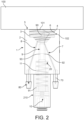
- the present invention is directed to a beverage dispenser connector 1 which can be best seen in Figures 2 to 4 .
- the beverage dispenser connector 1 comprises a dispenser body 2 defining a cavity 3 with an opening 4 to be open at a side 5 of the dispenser body 2.
- the beverage dispenser connector 1 further comprises a connection section 6 to attach the dispenser body 2 with the open cavity 3 over a delivery section 102 of a beverage ingredient container 100 to close the cavity 3 with the delivery section 102. This can be clearly seen in Figure 2 .
- the beverage dispenser connector 1 further comprises an inlet 7 to deliver a fluid into the cavity 3, as can also be clearly seen in Figure 2 .
- the inlet 7 may extend at least partially through the dispenser body 2, The inlet can be formed, for instance, as an integrally formed bore within the dispenser body 2.
- the inlet 7 may further comprise an inlet connection section 70 for connecting an inlet line (e.g. a hose, pipe, etc.) 270.
- the beverage dispenser connector 1 further comprises an outlet 8 to discharge the fluid out of the cavity 3.
- the outlet 8 may extend at least partially through the dispenser body 2 in a similar manner as defined for the inlet 7 described herein above.
- the outlet 8 may also be provided as an integrally formed bore within the dispenser body 2.
- the outlet 8 may comprise an outlet connection section 80 for connecting an outlet line (e.g. a hose, pipe, etc.) 280 to thus easily integrate the beverage dispenser connector 1 in a given supply system or beverage production device 200 as will be described in more detail herein below.
- the beverage dispenser connector 1 further comprises a needle 9 with a piercing tip 90 at a distal end thereof.
- the needle 9 is associated with the dispenser body 2 so as to be moveable between a retracted position (see Figure 2 ) in which the piercing tip 90 is positioned within the cavity 3, and an extended position (see Figures 3 and 4 ) in which the piercing tip 90 protrudes out of the cavity 3 via the opening 4.
- the beverage dispenser connector 1 may further comprise a triggering section 10 for selectively moving the needle 9 between the retracted position (e.g. Figure 2 ) and the extended position (e.g. Figures 3 and 4 ).
- the triggering section 10 can be configured to cooperate with a pneumatic actuator for selectively moving the needle 9.
- the triggering section 10 is part of a pneumatic cylinder 210 to allow for the pneumatic action be applied to the needle 9 for it to be moved.
- the triggering section 10 is preferably positioned at an end of the needle 9 being opposite to the piercing tip 90.
- this corresponding triggering section 10 is here provided at a lower portion of the needle 9 thus forming a part of a corresponding pneumatic cylinder 210.
- compressed fluid like compressed air
- the needle 9 will be pushed from the retracted position (see Figure 2 ) to the extended position (see Figure 3 and 4 ).
- the triggering section 10 may also be configured to cooperate with another type of actuator, e.g. a hydraulic, electric and/or mechanic actuator, for selectively moving the needle 9.
- the triggering section 10 may then be part of a corresponding hydraulic cylinder and/or comprises a gear to be connected to an electric motor and/or a crank.
- the triggering section 10 does not necessarily be positioned at an end of the needle 9 being opposite to the piercing tip 90, but it can also be positioned between the said end of the needle 9 and the piercing tip 90 or at any other location of the needle 9 being advantageous for applying a corresponding force to operate - i.e. move - the needle 9.
- the needle 9 can be forced/biased towards the retracted position, e.g. by a spring element 11 biased or loaded with a spring force at least during compression, i.e. when the needle 9 is moved from the retracted position to the extended position.
- the spring element 11 preferably sits between a flange section 91 of the needle 9 and an opposing stepped portion 20 in the dispenser body 2, as can be clearly seen in Figures 2 to 4 .
- the needle 9 may comprise a sealing element 92 for sealing off the inlet 7 from the cavity 3 in the extended position, as is clearly shown in Figures 3 and 4 .
- a sealing element 92 for sealing off the inlet 7 from the cavity 3 in the extended position, as is clearly shown in Figures 3 and 4 .
- the sealing element 92 further allows fluid flow from the inlet 7 to the cavity 3 in the retracted position (see Figure 2 ), as the sealing element 92 - in the retracted position of the needle 9 - releases the inlet 7 towards the cavity 3.
- the sealing element 92 may be an O-ring.
- the sealing element 92 may be positioned on the needle 9 and preferably partially sits in a circumferential outer groove 93 of the needle 9.
- the cavity 3 preferably comprises a first ring section 31 (here in the form of a cylindrical section) directly surrounding the piercing tip 90 in the retracted position (see Figure 2 ) of the needle 9, a second ring section 32 (here in the form of a cylindrical section) surrounding the first ring section 31 preferably at a defined radius R, and a sanitizing space 30 connecting the first ring section 31 and the second ring section 32 and being open towards the opening 4, i.e. facing the container 100 or its delivery section 102 during operation.
- a comparably small cavity 3 can be provided which allows for a defined fluid flow during a sanitizing process (see, e.g., Figure 4 ), which further ensures to avoid air bubbles being trapped within the cavity 3.
- air being trapped in the cavity 3 can be further avoided by the beverage dispenser connector 1 being oriented in an angled position.
- the inlet 7 preferably directly extends into the first ring section 31 and the outlet 8 directly extends from the second ring section 32. This allows for a defined and thus most efficient fluid flow and secure avoidance of any air being trapped within the cavity 3. This sanitization procedure is exemplarily shown in Figure 4 .
- the beverage dispenser connector 1 can be part of a beverage production device 200.
- the beverage dispenser connector 1 is then adapted to be connect to a delivery section 102 of a container 100 carrying a beverage ingredient.
- a liquid supply 201 is connected with the inlet 7 (e.g. via the inlet lines 270) for delivering a liquid into the cavity 3.
- the liquid supply 201 can comprise a water supply, preferably a hot water supply. Hence, water and preferably heated or hot water can be used as a sanitizing liquid for the beverage production device 200.
- the liquid supply 201 may further comprise a sanitizing liquid supply for supplying a sanitizing liquid other than (hot) water, e.g. a chemically based sanitization product/liquid.
- the beverage production device 200 further comprises a gas supply 202 being connected (e.g. via the inlet lines 270) with the inlet 7 for delivering a gas like air into the cavity 3.
- the gas supply 202 may comprise an air supply, like a compressor or any other kind of (compressed) air supply.
- the gas supply 202 may also be fluidly connected to the triggering section 10 as a pneumatic actuator for the needle 9.
- the beverage production device 200 preferably further comprises a heating element 207 for heating up the fluid in the liquid supply 201 (e.g. the water supply and/or the sanitizing liquid supply) and/or the gas supply 202.
- a heating element 207 for heating up the fluid in the liquid supply 201 (e.g. the water supply and/or the sanitizing liquid supply) and/or the gas supply 202.
- the beverage production device 200 further comprises a discharge section 203 being connected (e.g. via the outlet lines 280) with the outlet 8 for discharging a beverage ingredient from the cavity 3.
- the discharge section 203 comprises a discharge outlet 204 for dispensing a beverage product.
- a pump 208 like a peristaltic pump, may be provided between the beverage dispenser connector 1 and the discharge section 203, preferably integrated in-line in or with the outlet lines 280.
- the discharge section 203 may preferably further comprise a mixing chamber 205 being provided between the outlet 8 and the discharge outlet 204 for allowing a beverage product be mixed before being dispensed via the discharge section 203, i.e. the discharge outlet 204.
- the mixing chamber 205 is preferably connected to the liquid supply 201 (e.g. the water supply) and/or additional beverage ingredient container, preferably via a beverage dispenser connector 1 according to the present invention.
- the connection of the liquid/water supply 201 allows for water be directly delivered to the mixing chamber 205 as a basis for a beverage product, there be mixed by a desired combination of beverage ingredients from corresponding beverage ingredient containers preferably each being connected to the delivery system, i.e. the beverage production device 200, by a corresponding beverage dispenser connector 1.
- the direct connection of the liquid supply 201 to the mixing chamber 205 may allow for delivery of a sanitizing liquid directly into the mixing chamber 205, if desired.
- the water supply may be connected to a carbonisation system to add carbon dioxide to the water be used for the beverage production.
- the beverage ingredient container 100 to be used may be a foldable and preferably collapsible container 100 (see Figure 1D ), the delivery section 102 of which or its closure 101 being selectively protected - e.g. during transportation of the container 100 - by a removeable protection cap 103.
- Figure 1E the container 100 is shown in the unfolded operational state with the protective cap 103 be removed and thus the delivery section 102 be exposed.
- the container 100 can be collapsible to keep the aseptic characteristic of the beverage ingredient contained in the container 100.
- the beverage production device 200 may further comprise a container holder 206 for holding the beverage ingredient container 100 in place to be connected with the beverage dispenser connector 1. This is shown in Figure 1A with the unfolded container 100 positioned in place on the container holder 206.
- the beverage production device 200 or its container holder 206 may comprise a cooling section (here a cooling plate) 209 for cooling the container 100 being placed in/on/at the container holder 206.
- the content of the container 100 i.e. the beverage ingredient
- the beverage production device 200 or its container holder 206 may comprise a code reader (not shown) for identifying a code carried on a beverage ingredient container 100 preferably when being placed in/on/at the container holder 206.
- the code reader may be an optical reader or a wireless reader or any kind of code reader known in the prior art.
- a beverage production device 1 is provided with the needle 9 in the retraced position as shown, for instance, in Figure 2 .
- a container 100 carrying a beverage ingredient is provided, the container 100 having a delivery section 102 being sealed with a closure 101.
- the step of providing the beverage ingredient container 100 may further comprise the step of placing the beverage ingredient container 100 in/on/at the container holder 206.
- the container 100 can be securely hold in place, particularly with respect to the beverage dispenser connector 1.
- the container can be positioned in the container holder 206 for cooling the beverage ingredient container 100, i.e. its contents, by the cooling section 209 of the container holder 206.
- a code carried on the container 100 may be (automatically) read or identified by a code reader when the container 100 is placed in/on/at the container holder 206.
- the beverage dispenser connector 1 preferably its dispenser body 2 is attached with the open cavity 3 (i.e. with the opening 4 ahead) over the delivery section 102 of the container 100 to sealingly close the cavity 3 with the delivery section 102.
- a sanitizing liquid is delivered via the inlet 7 into the cavity 3 and preferably out of the cavity 3 via the outlet 8.
- a corresponding delivery section 102 of the container is sanitized.
- the piercing tip 90 of the needle 9 is also sanitized as being positioned within the cavity in the retracted position of the needle 9.
- a gas is delivered via the inlet 7 through the cavity 3 and out of the cavity 3 via the outlet 8 to drain the cavity 3 from sanitizing liquids.
- Steps 4 and 5 are shown exemplarily in Figures 2 and 4 .
- a sixth step and with reference to Figure 3 after drainage of the cavity 3, the needle 9 is moved from the retracted position to the extended position so that the piercing tip 90 penetrates the closure 101 to open the container 100. Due to the previous sanitizing step, bacterial or viral contamination of the beverage ingredient inside the container 100 can be securely avoided.
- the inlet 7 can be sealed, preferably by the needle 9 and more preferred by its sealing element 92, from the cavity 3 when being moved from the rejected position to the extended position to thus avoid further introduction of sanitizing liquids or air during beverage dispensing.
- the beverage ingredient is delivered out of the container 100 via the cavity 3 and the outlet 8 to a discharge section 203 for dispensing the beverage product.
- the beverage product can be mixed in the mixing chamber 205 of the discharge section 203 before being dispensed via the discharge section 203, i.e. the discharge outlet 204.
- water e.g. from the water supply, and/or additional beverage ingredients are delivered to the mixing chamber 205 to be mixed with the beverage ingredient delivered from the beverage ingredient container 100 before being dispensed via the discharge outlet 204.
Landscapes
- Engineering & Computer Science (AREA)
- Mechanical Engineering (AREA)
- Devices For Dispensing Beverages (AREA)
Claims (14)
- Getränkeabgabeeinrichtungsverbinder (1), umfassend- einen Abgabeeinrichtungskörper (2), der einen Hohlraum (3) mit einer Öffnung (4) definiert, um an einer Seite des Abgabeeinrichtungskörpers (2) offen zu sein,- einen Verbindungsabschnitt (6), um den Abgabeeinrichtungskörper (2) mit dem offenen Hohlraum (3) über einen Ausgabeabschnitt (102) eines Behälters (100) zu befestigen, um den Hohlraum (3) mit dem Ausgabeabschnitt (102) zu verschließen,- einen Einlass (7), um ein Fluid in den Hohlraum (3) auszugeben,- einen Auslass (8), um das Fluid aus dem Hohlraum (3) auszustoßen,- eine Nadel (9) mit einer Durchstechspitze (90), wobei die Nadel (9) dem Abgabeeinrichtungskörper (2) zugeordnet ist, so dass sie zwischen einer eingefahrenen Position, in der die Durchstechspitze (90) innerhalb des Hohlraums (3) positioniert ist, und einer ausgefahrenen Position, in der die Durchstechspitze (90) aus dem Hohlraum (3) über die Öffnung (4) herausragt, bewegbar ist,
dadurch gekennzeichnet, dass die Nadel (9) ein Dichtungselement (92) zum Abdichten des Einlasses (7) von dem Hohlraum (3) in der ausgefahrenen Position und Ermöglichen einer Fluidströmung von dem Einlass (7) zu dem Hohlraum (3) in der eingefahrenen Position umfasst. - Getränkeabgabeeinrichtungsverbinder (1) nach Anspruch 1, wobei sich der Einlass (7) mindestens teilweise durch den Abgabeeinrichtungskörper (2) erstreckt und/oder wobei sich der Auslass (8) mindestens teilweise durch den Abgabeeinrichtungskörper (2) erstreckt.
- Getränkeabgabeeinrichtungsverbinder (1) nach einem der vorstehenden Ansprüche, wobei der Einlass (7) einen Einlassverbindungsabschnitt (70) zum Verbinden einer Einlassleitung (270) umfasst und/oder wobei der Auslass (8) einen Auslassverbindungsabschnitt (80) zum Verbinden einer Auslassleitung (280) umfasst.
- Getränkeabgabeeinrichtungsverbinder (1) nach einem der vorstehenden Ansprüche, ferner umfassend einen Auslöseabschnitt (10) zum wahlweisen Bewegen der Nadel (9) zwischen der eingefahrenen Position und der ausgefahrenen Position,
wobei der Auslöseabschnitt (10) vorzugsweise an einem Ende der Nadel (9), das der Durchstechspitze (90) gegenüberliegt, oder zwischen dem Ende der Nadel (9) und der Durchstechspitze (90) positioniert ist. - Getränkeabgabeeinrichtungsverbinder (1) nach Anspruch 4, wobei der Auslöseabschnitt (10) konfiguriert ist, um mit einem pneumatischen, hydraulischen, elektrischen oder mechanischen Aktuator (202) zum wahlweisen Bewegen der Nadel (9) zusammenzuwirken, wobei der Auslöseabschnitt (10) Teil eines pneumatischen oder hydraulischen Zylinders (210) ist und/oder ein Getriebe umfasst, um mit einem Elektromotor oder einer Kurbel verbunden zu werden.
- Getränkeabgabeeinrichtungsverbinder (1) nach einem der vorstehenden Ansprüche, wobei der Hohlraum (3) einen ersten Ringabschnitt (31), der die Durchstechspitze (90) in der eingefahrenen Position der Nadel (9) direkt umgibt, einen zweiten Ringabschnitt (32), der den ersten Ringabschnitt (31) vorzugsweise in einem definierten Radius (R) umgibt, und einen Desinfektionsraum (30), der den ersten Ringabschnitt (31) und den zweiten Ringabschnitt (32) verbindet und in Richtung der Öffnung (4) offen ist, umfasst,
wobei sich vorzugsweise der Einlass (7) direkt in den ersten Ringabschnitt (31) erstreckt und sich der Auslass (8) direkt von dem zweiten Ringabschnitt (32) erstreckt. - Getränkeproduktionsvorrichtung (200), umfassend:- einen Getränkeabgabeeinrichtungsverbinder (1) nach einem der vorstehenden Ansprüche, der angepasst ist, um mit einem Ausgabeabschnitt (102) eines Behälters (100), der eine Getränkezutat trägt, verbunden zu werden,- eine Flüssigkeitszufuhr (201), die mit dem Einlass (7) zum Ausgeben einer Flüssigkeit in den Hohlraum (3) verbunden ist,- eine Gaszufuhr (202), die mit dem Einlass (7) zum Ausgeben eines Gases in den Hohlraum (3) verbunden ist,- einen Ausstoßabschnitt (203), der mit dem Auslass (8) zum Ausstoßen einer Getränkezutat aus dem Hohlraum (3) verbunden ist, wobei der Ausstoßabschnitt (203) einen Ausstoßauslass (204) zum Abgeben eines Getränkeprodukts umfasst.
- Getränkeproduktionsvorrichtung (200) nach Anspruch 7, wobei die Flüssigkeitszufuhr (201) eine Wasserzufuhr und/oder eine Desinfektionsflüssigkeitszufuhr umfasst, und/oderwobei die Gaszufuhr (202) eine Luftzufuhr, vorzugsweise einen Kompressor, umfasst,wobei die Getränkeproduktionsvorrichtung (200) vorzugsweise ferner ein Heizelement (207) zum Erhitzen des Fluids in der Flüssigkeitszufuhr (201) und/oder der Gaszufuhr (202) umfasst.
- Getränkeproduktionsvorrichtung (200) nach Anspruch 7 oder 8, wobei der Ausstoßabschnitt (203) ferner eine Mischkammer (205), die zwischen dem Auslass (8) und dem Ausstoßauslass (204) bereitgestellt ist, zum Ermöglichen umfasst, dass ein Getränkeprodukt gemischt wird, bevor es über den Ausstoßauslass (204) abgegeben wird, wobei die Mischkammer (205) vorzugsweise mit der Flüssigkeitszufuhr (201), stärker bevorzugt mit der Wasserzufuhr, und/oder mit einem zusätzlichen Getränkezutatenbehälter (100), vorzugsweise über den Getränkeabgabeeinrichtungsverbinder (1), verbunden ist.
- Getränkeproduktionsvorrichtung (200) nach einem der Ansprüche 7 bis 9, ferner umfassend einen Behälterhalter (206) zum Halten eines Getränkezutatenbehälters (100) an Ort und Stelle, um mit dem Getränkeabgabeeinrichtungsverbinder (1) verbunden zu werden, wobei die vorzugsweise die Getränkeproduktionsvorrichtung (200) und stärker bevorzugt ihr Behälterhalter (206) umfasst:- einen Kühlabschnitt (209) zum Kühlen eines Behälters, der in/auf/an dem Behälterhalter (206) platziert ist,- einen Codeleser zum Identifizieren eines Codes, der auf einem Getränkezutatenbehälter (100) getragen wird, vorzugsweise wenn er in/auf/an dem Behälterhalter (206) platziert ist.
- Getränkeproduktionsverfahren, umfassend die Schritte:- Bereitstellen einer Getränkeproduktionsvorrichtung (200) nach einem der Ansprüche 7 bis 10 mit der Nadel (9) in der eingefahrenen Position,- Bereitstellen eines Behälters (100), der eine Getränkezutat trägt und einen Ausgabeabschnitt (102) aufweist, der mit einem Verschluss (101) abgedichtet ist,- Befestigen des Abgabeeinrichtungskörpers (2) mit dem offenen Hohlraum (3) über den Ausgabeabschnitt (102) des Behälters (100), um den Hohlraum (3) mit dem Ausgabeabschnitt (102) dichtend zu verschließen,- Ausgeben einer Desinfektionsflüssigkeit über den Einlass (7) in den Hohlraum (3) und vorzugsweise aus dem Hohlraum (3) über den Auslass (8),- nach der Ausgabe der Desinfektionsflüssigkeit, Ausgeben eines Gases über den Einlass (7) durch den Hohlraum (3) und aus dem Hohlraum (3) heraus über den Auslass (8), um den Hohlraum (3) von Desinfektionsflüssigkeit zu entleeren,- nach dem Entleeren des Hohlraums (3), Bewegen der Nadel (9) von der eingefahrenen Position in die ausgefahrene Position, sodass die Durchstechspitze (90) den Verschluss (101) durchdringt, um den Behälter (100) zu öffnen, und- Ausgeben der Getränkezutat aus dem Behälter (100) über den Hohlraum (3) und den Auslass (8) an den Ausstoßabschnitt (203) zum Abgeben eines Getränkeprodukts.
- Verfahren nach Anspruch 11, wobei der Einlass (7) von dem Hohlraum (3), vorzugsweise durch die Nadel (9), abgedichtet ist, wenn die Nadel (9) von der eingefahrenen Position in die ausgefahrene Position bewegt wird.
- Verfahren nach Anspruch 11 oder 12, wobei das Bereitstellen des Getränkezutatenbehälters (100) den Schritt des Platzierens des Getränkezutatenbehälters (100) in/auf/an dem Behälterhalter (206), vorzugsweise zum Kühlen des Getränkezutatenbehälters (100) durch den Kühlabschnitt (209) des Behälterhalters (206) umfasst.
- Verfahren nach einem der Ansprüche 11 bis 13, wobei das Getränkeprodukt in der Mischkammer (205) des Abgabeabschnitts (203) gemischt wird, bevor es über den Ausstoßauslass (204) abgegeben wird,
wobei vorzugsweise Wasser, z. B. von der Wasserzufuhr, und/oder zusätzliche Getränkezutaten an die Mischkammer (205) ausgegeben werden, um mit der Getränkezutat, die von dem Getränkezutatenbehälter (1) ausgegeben wird, gemischt zu werden, bevor sie über den Ausstoßauslass (204) abgegeben werden.
Applications Claiming Priority (2)
| Application Number | Priority Date | Filing Date | Title |
|---|---|---|---|
| EP20166172 | 2020-03-27 | ||
| PCT/EP2021/057336 WO2021191173A1 (en) | 2020-03-27 | 2021-03-23 | Beverage dispenser connector, beverage production device and method for beverage production |
Publications (2)
| Publication Number | Publication Date |
|---|---|
| EP4126751A1 EP4126751A1 (de) | 2023-02-08 |
| EP4126751B1 true EP4126751B1 (de) | 2024-01-24 |
Family
ID=70056857
Family Applications (1)
| Application Number | Title | Priority Date | Filing Date |
|---|---|---|---|
| EP21713026.9A Active EP4126751B1 (de) | 2020-03-27 | 2021-03-23 | Getränkeausgabeverbinder, getränkeherstellungsvorrichtung und verfahren zur getränkeherstellung |
Country Status (3)
| Country | Link |
|---|---|
| US (1) | US12258259B2 (de) |
| EP (1) | EP4126751B1 (de) |
| WO (1) | WO2021191173A1 (de) |
Families Citing this family (1)
| Publication number | Priority date | Publication date | Assignee | Title |
|---|---|---|---|---|
| WO2021191173A1 (en) * | 2020-03-27 | 2021-09-30 | Societe Des Produits Nestle S.A. | Beverage dispenser connector, beverage production device and method for beverage production |
Citations (1)
| Publication number | Priority date | Publication date | Assignee | Title |
|---|---|---|---|---|
| JP4349985B2 (ja) * | 2004-07-15 | 2009-10-21 | フジテクノ株式会社 | 飲料サーバーおよび飲料サーバー用接続部 |
Family Cites Families (14)
| Publication number | Priority date | Publication date | Assignee | Title |
|---|---|---|---|---|
| CA2547135A1 (en) * | 2003-10-23 | 2005-05-06 | Don Miller | Container adapted to hold and dispense bagged fluids |
| US7347345B2 (en) * | 2004-06-02 | 2008-03-25 | Nestec S.A. | Device and method for hygienically delivering a liquid food |
| JP2006044698A (ja) | 2004-08-02 | 2006-02-16 | Sanden Corp | 飲料ディスペンサ |
| EP2017221A1 (de) | 2007-07-19 | 2009-01-21 | Nestec, Ltd. | Vorrichtung zur Abgabe einer Flüssigkeit |
| JP3164948U (ja) * | 2010-10-12 | 2010-12-24 | 慎一 矢野 | ウォーターサーバーに用いるニードル |
| US10202269B2 (en) * | 2011-12-26 | 2019-02-12 | Neviot—Nature Of Galilee Ltd. | Beverage dispenser and method for sanitation thereof |
| JP5855803B2 (ja) * | 2012-10-05 | 2016-02-09 | ネステク ソシエテ アノニム | 逆止め弁、注入アセンブリ、および飲料調製マシン |
| EP2906087B1 (de) * | 2012-10-09 | 2016-08-31 | Nestec S.A. | Getränkeherstellungsvorrichtung mit perforiervorrichtung und verfahren zur extraktion eines getränks aus einer derartigen vorrichtung |
| JP6227922B2 (ja) | 2013-08-01 | 2017-11-08 | 株式会社千石 | ウオーターサーバー |
| US9932218B2 (en) * | 2016-03-04 | 2018-04-03 | BIBO Barmaid LLC | Cold beverage dispenser and cutter assembly for cold beverage dispenser |
| FR3044653B1 (fr) * | 2015-12-08 | 2017-12-01 | 10-Vins | Installation pour la preparation a la degustation de boisson et procede d'ouverture d'un contenant de boisson a l'aide d'une telle installation |
| SE543593C2 (sv) * | 2017-09-27 | 2021-04-06 | Asept Int Ab | Kopplingsanordning för anslutning till en flexibel container för utmatning av livsmedelsprodukt |
| WO2021191173A1 (en) * | 2020-03-27 | 2021-09-30 | Societe Des Produits Nestle S.A. | Beverage dispenser connector, beverage production device and method for beverage production |
| EP4126749B1 (de) * | 2020-03-30 | 2025-07-23 | Société des Produits Nestlé S.A. | Getränkemischvorrichtung, getränkezubereitungsvorrichtung und verfahren zur herstellung eines getränkeprodukts |
-
2021
- 2021-03-23 WO PCT/EP2021/057336 patent/WO2021191173A1/en not_active Ceased
- 2021-03-23 US US17/906,516 patent/US12258259B2/en active Active
- 2021-03-23 EP EP21713026.9A patent/EP4126751B1/de active Active
Patent Citations (1)
| Publication number | Priority date | Publication date | Assignee | Title |
|---|---|---|---|---|
| JP4349985B2 (ja) * | 2004-07-15 | 2009-10-21 | フジテクノ株式会社 | 飲料サーバーおよび飲料サーバー用接続部 |
Also Published As
| Publication number | Publication date |
|---|---|
| WO2021191173A1 (en) | 2021-09-30 |
| EP4126751A1 (de) | 2023-02-08 |
| US12258259B2 (en) | 2025-03-25 |
| US20230242392A1 (en) | 2023-08-03 |
Similar Documents
| Publication | Publication Date | Title |
|---|---|---|
| US12281001B2 (en) | Beverage mixing device, beverage preparation device and method for preparing a beverage product | |
| EP2417052B1 (de) | Einsatz mit mischdüse und mischflüssigkeitspender | |
| US12245717B2 (en) | System for multi-ingredient beverage preparation from various container types | |
| US6116467A (en) | Beverage dispensing system | |
| US8910833B2 (en) | Dispensing machine valve and method | |
| EP2383553A1 (de) | Verpackung zur Lagerung und Dosierung einer Flüssigkeit | |
| JP2008050061A (ja) | 飲料濃縮液を分配するためのシステムおよび方法 | |
| JP2015504392A (ja) | 容器用アダプタ | |
| US12258259B2 (en) | Beverage dispenser connector, beverage production device and method for beverage production | |
| US20210206615A1 (en) | Mixing nozzle fitment | |
| US20140251147A1 (en) | Filter cap for filtering and dispensing a nutritional composition | |
| BE1017579A5 (nl) | Apparaat voor een multidrink systeem. | |
| US20200047988A1 (en) | Capsule |
Legal Events
| Date | Code | Title | Description |
|---|---|---|---|
| STAA | Information on the status of an ep patent application or granted ep patent |
Free format text: STATUS: UNKNOWN |
|
| STAA | Information on the status of an ep patent application or granted ep patent |
Free format text: STATUS: THE INTERNATIONAL PUBLICATION HAS BEEN MADE |
|
| PUAI | Public reference made under article 153(3) epc to a published international application that has entered the european phase |
Free format text: ORIGINAL CODE: 0009012 |
|
| STAA | Information on the status of an ep patent application or granted ep patent |
Free format text: STATUS: REQUEST FOR EXAMINATION WAS MADE |
|
| 17P | Request for examination filed |
Effective date: 20221027 |
|
| AK | Designated contracting states |
Kind code of ref document: A1 Designated state(s): AL AT BE BG CH CY CZ DE DK EE ES FI FR GB GR HR HU IE IS IT LI LT LU LV MC MK MT NL NO PL PT RO RS SE SI SK SM TR |
|
| DAV | Request for validation of the european patent (deleted) | ||
| DAX | Request for extension of the european patent (deleted) | ||
| P01 | Opt-out of the competence of the unified patent court (upc) registered |
Effective date: 20230527 |
|
| GRAP | Despatch of communication of intention to grant a patent |
Free format text: ORIGINAL CODE: EPIDOSNIGR1 |
|
| STAA | Information on the status of an ep patent application or granted ep patent |
Free format text: STATUS: GRANT OF PATENT IS INTENDED |
|
| INTG | Intention to grant announced |
Effective date: 20230915 |
|
| GRAS | Grant fee paid |
Free format text: ORIGINAL CODE: EPIDOSNIGR3 |
|
| GRAA | (expected) grant |
Free format text: ORIGINAL CODE: 0009210 |
|
| STAA | Information on the status of an ep patent application or granted ep patent |
Free format text: STATUS: THE PATENT HAS BEEN GRANTED |
|
| AK | Designated contracting states |
Kind code of ref document: B1 Designated state(s): AL AT BE BG CH CY CZ DE DK EE ES FI FR GB GR HR HU IE IS IT LI LT LU LV MC MK MT NL NO PL PT RO RS SE SI SK SM TR |
|
| REG | Reference to a national code |
Ref country code: GB Ref legal event code: FG4D |
|
| REG | Reference to a national code |
Ref country code: CH Ref legal event code: EP |
|
| REG | Reference to a national code |
Ref country code: DE Ref legal event code: R096 Ref document number: 602021008755 Country of ref document: DE |
|
| REG | Reference to a national code |
Ref country code: IE Ref legal event code: FG4D |
|
| REG | Reference to a national code |
Ref country code: NL Ref legal event code: FP |
|
| REG | Reference to a national code |
Ref country code: LT Ref legal event code: MG9D |
|
| PG25 | Lapsed in a contracting state [announced via postgrant information from national office to epo] |
Ref country code: IS Free format text: LAPSE BECAUSE OF FAILURE TO SUBMIT A TRANSLATION OF THE DESCRIPTION OR TO PAY THE FEE WITHIN THE PRESCRIBED TIME-LIMIT Effective date: 20240524 |
|
| PG25 | Lapsed in a contracting state [announced via postgrant information from national office to epo] |
Ref country code: LT Free format text: LAPSE BECAUSE OF FAILURE TO SUBMIT A TRANSLATION OF THE DESCRIPTION OR TO PAY THE FEE WITHIN THE PRESCRIBED TIME-LIMIT Effective date: 20240124 |
|
| PG25 | Lapsed in a contracting state [announced via postgrant information from national office to epo] |
Ref country code: GR Free format text: LAPSE BECAUSE OF FAILURE TO SUBMIT A TRANSLATION OF THE DESCRIPTION OR TO PAY THE FEE WITHIN THE PRESCRIBED TIME-LIMIT Effective date: 20240425 |
|
| REG | Reference to a national code |
Ref country code: AT Ref legal event code: MK05 Ref document number: 1652073 Country of ref document: AT Kind code of ref document: T Effective date: 20240124 |
|
| PG25 | Lapsed in a contracting state [announced via postgrant information from national office to epo] |
Ref country code: HR Free format text: LAPSE BECAUSE OF FAILURE TO SUBMIT A TRANSLATION OF THE DESCRIPTION OR TO PAY THE FEE WITHIN THE PRESCRIBED TIME-LIMIT Effective date: 20240124 Ref country code: RS Free format text: LAPSE BECAUSE OF FAILURE TO SUBMIT A TRANSLATION OF THE DESCRIPTION OR TO PAY THE FEE WITHIN THE PRESCRIBED TIME-LIMIT Effective date: 20240424 |
|
| PG25 | Lapsed in a contracting state [announced via postgrant information from national office to epo] |
Ref country code: ES Free format text: LAPSE BECAUSE OF FAILURE TO SUBMIT A TRANSLATION OF THE DESCRIPTION OR TO PAY THE FEE WITHIN THE PRESCRIBED TIME-LIMIT Effective date: 20240124 |
|
| PG25 | Lapsed in a contracting state [announced via postgrant information from national office to epo] |
Ref country code: AT Free format text: LAPSE BECAUSE OF FAILURE TO SUBMIT A TRANSLATION OF THE DESCRIPTION OR TO PAY THE FEE WITHIN THE PRESCRIBED TIME-LIMIT Effective date: 20240124 |
|
| PG25 | Lapsed in a contracting state [announced via postgrant information from national office to epo] |
Ref country code: RS Free format text: LAPSE BECAUSE OF FAILURE TO SUBMIT A TRANSLATION OF THE DESCRIPTION OR TO PAY THE FEE WITHIN THE PRESCRIBED TIME-LIMIT Effective date: 20240424 Ref country code: NO Free format text: LAPSE BECAUSE OF FAILURE TO SUBMIT A TRANSLATION OF THE DESCRIPTION OR TO PAY THE FEE WITHIN THE PRESCRIBED TIME-LIMIT Effective date: 20240424 Ref country code: LT Free format text: LAPSE BECAUSE OF FAILURE TO SUBMIT A TRANSLATION OF THE DESCRIPTION OR TO PAY THE FEE WITHIN THE PRESCRIBED TIME-LIMIT Effective date: 20240124 Ref country code: IS Free format text: LAPSE BECAUSE OF FAILURE TO SUBMIT A TRANSLATION OF THE DESCRIPTION OR TO PAY THE FEE WITHIN THE PRESCRIBED TIME-LIMIT Effective date: 20240524 Ref country code: HR Free format text: LAPSE BECAUSE OF FAILURE TO SUBMIT A TRANSLATION OF THE DESCRIPTION OR TO PAY THE FEE WITHIN THE PRESCRIBED TIME-LIMIT Effective date: 20240124 Ref country code: GR Free format text: LAPSE BECAUSE OF FAILURE TO SUBMIT A TRANSLATION OF THE DESCRIPTION OR TO PAY THE FEE WITHIN THE PRESCRIBED TIME-LIMIT Effective date: 20240425 Ref country code: FI Free format text: LAPSE BECAUSE OF FAILURE TO SUBMIT A TRANSLATION OF THE DESCRIPTION OR TO PAY THE FEE WITHIN THE PRESCRIBED TIME-LIMIT Effective date: 20240124 Ref country code: ES Free format text: LAPSE BECAUSE OF FAILURE TO SUBMIT A TRANSLATION OF THE DESCRIPTION OR TO PAY THE FEE WITHIN THE PRESCRIBED TIME-LIMIT Effective date: 20240124 Ref country code: BG Free format text: LAPSE BECAUSE OF FAILURE TO SUBMIT A TRANSLATION OF THE DESCRIPTION OR TO PAY THE FEE WITHIN THE PRESCRIBED TIME-LIMIT Effective date: 20240124 Ref country code: AT Free format text: LAPSE BECAUSE OF FAILURE TO SUBMIT A TRANSLATION OF THE DESCRIPTION OR TO PAY THE FEE WITHIN THE PRESCRIBED TIME-LIMIT Effective date: 20240124 |
|
| PG25 | Lapsed in a contracting state [announced via postgrant information from national office to epo] |
Ref country code: PT Free format text: LAPSE BECAUSE OF FAILURE TO SUBMIT A TRANSLATION OF THE DESCRIPTION OR TO PAY THE FEE WITHIN THE PRESCRIBED TIME-LIMIT Effective date: 20240524 Ref country code: PL Free format text: LAPSE BECAUSE OF FAILURE TO SUBMIT A TRANSLATION OF THE DESCRIPTION OR TO PAY THE FEE WITHIN THE PRESCRIBED TIME-LIMIT Effective date: 20240124 |
|
| PG25 | Lapsed in a contracting state [announced via postgrant information from national office to epo] |
Ref country code: SE Free format text: LAPSE BECAUSE OF FAILURE TO SUBMIT A TRANSLATION OF THE DESCRIPTION OR TO PAY THE FEE WITHIN THE PRESCRIBED TIME-LIMIT Effective date: 20240124 Ref country code: PT Free format text: LAPSE BECAUSE OF FAILURE TO SUBMIT A TRANSLATION OF THE DESCRIPTION OR TO PAY THE FEE WITHIN THE PRESCRIBED TIME-LIMIT Effective date: 20240524 Ref country code: PL Free format text: LAPSE BECAUSE OF FAILURE TO SUBMIT A TRANSLATION OF THE DESCRIPTION OR TO PAY THE FEE WITHIN THE PRESCRIBED TIME-LIMIT Effective date: 20240124 Ref country code: LV Free format text: LAPSE BECAUSE OF FAILURE TO SUBMIT A TRANSLATION OF THE DESCRIPTION OR TO PAY THE FEE WITHIN THE PRESCRIBED TIME-LIMIT Effective date: 20240124 |
|
| PG25 | Lapsed in a contracting state [announced via postgrant information from national office to epo] |
Ref country code: DK Free format text: LAPSE BECAUSE OF FAILURE TO SUBMIT A TRANSLATION OF THE DESCRIPTION OR TO PAY THE FEE WITHIN THE PRESCRIBED TIME-LIMIT Effective date: 20240124 |
|
| PG25 | Lapsed in a contracting state [announced via postgrant information from national office to epo] |
Ref country code: SM Free format text: LAPSE BECAUSE OF FAILURE TO SUBMIT A TRANSLATION OF THE DESCRIPTION OR TO PAY THE FEE WITHIN THE PRESCRIBED TIME-LIMIT Effective date: 20240124 |
|
| PG25 | Lapsed in a contracting state [announced via postgrant information from national office to epo] |
Ref country code: CZ Free format text: LAPSE BECAUSE OF FAILURE TO SUBMIT A TRANSLATION OF THE DESCRIPTION OR TO PAY THE FEE WITHIN THE PRESCRIBED TIME-LIMIT Effective date: 20240124 Ref country code: EE Free format text: LAPSE BECAUSE OF FAILURE TO SUBMIT A TRANSLATION OF THE DESCRIPTION OR TO PAY THE FEE WITHIN THE PRESCRIBED TIME-LIMIT Effective date: 20240124 |
|
| REG | Reference to a national code |
Ref country code: DE Ref legal event code: R097 Ref document number: 602021008755 Country of ref document: DE |
|
| PG25 | Lapsed in a contracting state [announced via postgrant information from national office to epo] |
Ref country code: SK Free format text: LAPSE BECAUSE OF FAILURE TO SUBMIT A TRANSLATION OF THE DESCRIPTION OR TO PAY THE FEE WITHIN THE PRESCRIBED TIME-LIMIT Effective date: 20240124 |
|
| PG25 | Lapsed in a contracting state [announced via postgrant information from national office to epo] |
Ref country code: SM Free format text: LAPSE BECAUSE OF FAILURE TO SUBMIT A TRANSLATION OF THE DESCRIPTION OR TO PAY THE FEE WITHIN THE PRESCRIBED TIME-LIMIT Effective date: 20240124 Ref country code: SK Free format text: LAPSE BECAUSE OF FAILURE TO SUBMIT A TRANSLATION OF THE DESCRIPTION OR TO PAY THE FEE WITHIN THE PRESCRIBED TIME-LIMIT Effective date: 20240124 Ref country code: EE Free format text: LAPSE BECAUSE OF FAILURE TO SUBMIT A TRANSLATION OF THE DESCRIPTION OR TO PAY THE FEE WITHIN THE PRESCRIBED TIME-LIMIT Effective date: 20240124 Ref country code: DK Free format text: LAPSE BECAUSE OF FAILURE TO SUBMIT A TRANSLATION OF THE DESCRIPTION OR TO PAY THE FEE WITHIN THE PRESCRIBED TIME-LIMIT Effective date: 20240124 Ref country code: CZ Free format text: LAPSE BECAUSE OF FAILURE TO SUBMIT A TRANSLATION OF THE DESCRIPTION OR TO PAY THE FEE WITHIN THE PRESCRIBED TIME-LIMIT Effective date: 20240124 |
|
| PG25 | Lapsed in a contracting state [announced via postgrant information from national office to epo] |
Ref country code: LU Free format text: LAPSE BECAUSE OF NON-PAYMENT OF DUE FEES Effective date: 20240323 |
|
| PG25 | Lapsed in a contracting state [announced via postgrant information from national office to epo] |
Ref country code: MC Free format text: LAPSE BECAUSE OF FAILURE TO SUBMIT A TRANSLATION OF THE DESCRIPTION OR TO PAY THE FEE WITHIN THE PRESCRIBED TIME-LIMIT Effective date: 20240124 |
|
| PG25 | Lapsed in a contracting state [announced via postgrant information from national office to epo] |
Ref country code: MC Free format text: LAPSE BECAUSE OF FAILURE TO SUBMIT A TRANSLATION OF THE DESCRIPTION OR TO PAY THE FEE WITHIN THE PRESCRIBED TIME-LIMIT Effective date: 20240124 Ref country code: LU Free format text: LAPSE BECAUSE OF NON-PAYMENT OF DUE FEES Effective date: 20240323 |
|
| PLBE | No opposition filed within time limit |
Free format text: ORIGINAL CODE: 0009261 |
|
| STAA | Information on the status of an ep patent application or granted ep patent |
Free format text: STATUS: NO OPPOSITION FILED WITHIN TIME LIMIT |
|
| REG | Reference to a national code |
Ref country code: BE Ref legal event code: MM Effective date: 20240331 |
|
| 26N | No opposition filed |
Effective date: 20241025 |
|
| PG25 | Lapsed in a contracting state [announced via postgrant information from national office to epo] |
Ref country code: BE Free format text: LAPSE BECAUSE OF NON-PAYMENT OF DUE FEES Effective date: 20240331 |
|
| PG25 | Lapsed in a contracting state [announced via postgrant information from national office to epo] |
Ref country code: IE Free format text: LAPSE BECAUSE OF NON-PAYMENT OF DUE FEES Effective date: 20240323 |
|
| PG25 | Lapsed in a contracting state [announced via postgrant information from national office to epo] |
Ref country code: IE Free format text: LAPSE BECAUSE OF NON-PAYMENT OF DUE FEES Effective date: 20240323 Ref country code: BE Free format text: LAPSE BECAUSE OF NON-PAYMENT OF DUE FEES Effective date: 20240331 |
|
| PG25 | Lapsed in a contracting state [announced via postgrant information from national office to epo] |
Ref country code: SI Free format text: LAPSE BECAUSE OF FAILURE TO SUBMIT A TRANSLATION OF THE DESCRIPTION OR TO PAY THE FEE WITHIN THE PRESCRIBED TIME-LIMIT Effective date: 20240124 |
|
| PG25 | Lapsed in a contracting state [announced via postgrant information from national office to epo] |
Ref country code: RO Free format text: LAPSE BECAUSE OF FAILURE TO SUBMIT A TRANSLATION OF THE DESCRIPTION OR TO PAY THE FEE WITHIN THE PRESCRIBED TIME-LIMIT Effective date: 20240124 |
|
| PGFP | Annual fee paid to national office [announced via postgrant information from national office to epo] |
Ref country code: CH Payment date: 20250401 Year of fee payment: 5 |
|
| PG25 | Lapsed in a contracting state [announced via postgrant information from national office to epo] |
Ref country code: CY Free format text: LAPSE BECAUSE OF FAILURE TO SUBMIT A TRANSLATION OF THE DESCRIPTION OR TO PAY THE FEE WITHIN THE PRESCRIBED TIME-LIMIT; INVALID AB INITIO Effective date: 20210323 |
|
| PG25 | Lapsed in a contracting state [announced via postgrant information from national office to epo] |
Ref country code: HU Free format text: LAPSE BECAUSE OF FAILURE TO SUBMIT A TRANSLATION OF THE DESCRIPTION OR TO PAY THE FEE WITHIN THE PRESCRIBED TIME-LIMIT; INVALID AB INITIO Effective date: 20210323 |
|
| GBPC | Gb: european patent ceased through non-payment of renewal fee |
Effective date: 20250323 |
|
| PG25 | Lapsed in a contracting state [announced via postgrant information from national office to epo] |
Ref country code: TR Free format text: LAPSE BECAUSE OF FAILURE TO SUBMIT A TRANSLATION OF THE DESCRIPTION OR TO PAY THE FEE WITHIN THE PRESCRIBED TIME-LIMIT Effective date: 20240124 |
|
| PG25 | Lapsed in a contracting state [announced via postgrant information from national office to epo] |
Ref country code: GB Free format text: LAPSE BECAUSE OF NON-PAYMENT OF DUE FEES Effective date: 20250323 |
|
| PGFP | Annual fee paid to national office [announced via postgrant information from national office to epo] |
Ref country code: NL Payment date: 20260213 Year of fee payment: 6 |
|
| REG | Reference to a national code |
Ref country code: CH Ref legal event code: U11 Free format text: ST27 STATUS EVENT CODE: U-0-0-U10-U11 (AS PROVIDED BY THE NATIONAL OFFICE) Effective date: 20260401 |
|
| PGFP | Annual fee paid to national office [announced via postgrant information from national office to epo] |
Ref country code: DE Payment date: 20260204 Year of fee payment: 6 |
|
| PGFP | Annual fee paid to national office [announced via postgrant information from national office to epo] |
Ref country code: IT Payment date: 20260220 Year of fee payment: 6 |
|
| PGFP | Annual fee paid to national office [announced via postgrant information from national office to epo] |
Ref country code: FR Payment date: 20260209 Year of fee payment: 6 |