EP4126565B1 - Reifen mit optimierter lauffläche in bezug auf die haftung auf trockenem boden - Google Patents
Reifen mit optimierter lauffläche in bezug auf die haftung auf trockenem boden Download PDFInfo
- Publication number
- EP4126565B1 EP4126565B1 EP21717148.7A EP21717148A EP4126565B1 EP 4126565 B1 EP4126565 B1 EP 4126565B1 EP 21717148 A EP21717148 A EP 21717148A EP 4126565 B1 EP4126565 B1 EP 4126565B1
- Authority
- EP
- European Patent Office
- Prior art keywords
- tread
- elements
- equal
- pitch
- tread pattern
- Prior art date
- Legal status (The legal status is an assumption and is not a legal conclusion. Google has not performed a legal analysis and makes no representation as to the accuracy of the status listed.)
- Active
Links
Images


Classifications
-
- B—PERFORMING OPERATIONS; TRANSPORTING
- B60—VEHICLES IN GENERAL
- B60C—VEHICLE TYRES; TYRE INFLATION; TYRE CHANGING; CONNECTING VALVES TO INFLATABLE ELASTIC BODIES IN GENERAL; DEVICES OR ARRANGEMENTS RELATED TO TYRES
- B60C11/00—Tyre tread bands; Tread patterns; Anti-skid inserts
- B60C11/03—Tread patterns
- B60C11/0302—Tread patterns directional pattern, i.e. with main rolling direction
-
- B—PERFORMING OPERATIONS; TRANSPORTING
- B60—VEHICLES IN GENERAL
- B60C—VEHICLE TYRES; TYRE INFLATION; TYRE CHANGING; CONNECTING VALVES TO INFLATABLE ELASTIC BODIES IN GENERAL; DEVICES OR ARRANGEMENTS RELATED TO TYRES
- B60C11/00—Tyre tread bands; Tread patterns; Anti-skid inserts
- B60C11/03—Tread patterns
- B60C11/0318—Tread patterns irregular patterns with particular pitch sequence
-
- B—PERFORMING OPERATIONS; TRANSPORTING
- B60—VEHICLES IN GENERAL
- B60C—VEHICLE TYRES; TYRE INFLATION; TYRE CHANGING; CONNECTING VALVES TO INFLATABLE ELASTIC BODIES IN GENERAL; DEVICES OR ARRANGEMENTS RELATED TO TYRES
- B60C11/00—Tyre tread bands; Tread patterns; Anti-skid inserts
- B60C11/03—Tread patterns
- B60C11/0327—Tread patterns characterised by special properties of the tread pattern
- B60C11/033—Tread patterns characterised by special properties of the tread pattern by the void or net-to-gross ratios of the patterns
-
- B—PERFORMING OPERATIONS; TRANSPORTING
- B60—VEHICLES IN GENERAL
- B60C—VEHICLE TYRES; TYRE INFLATION; TYRE CHANGING; CONNECTING VALVES TO INFLATABLE ELASTIC BODIES IN GENERAL; DEVICES OR ARRANGEMENTS RELATED TO TYRES
- B60C11/00—Tyre tread bands; Tread patterns; Anti-skid inserts
- B60C11/03—Tread patterns
- B60C11/13—Tread patterns characterised by the groove cross-section, e.g. for buttressing or preventing stone-trapping
- B60C11/1376—Three dimensional block surfaces departing from the enveloping tread contour
- B60C11/1392—Three dimensional block surfaces departing from the enveloping tread contour with chamfered block edges
-
- B—PERFORMING OPERATIONS; TRANSPORTING
- B60—VEHICLES IN GENERAL
- B60C—VEHICLE TYRES; TYRE INFLATION; TYRE CHANGING; CONNECTING VALVES TO INFLATABLE ELASTIC BODIES IN GENERAL; DEVICES OR ARRANGEMENTS RELATED TO TYRES
- B60C13/00—Tyre sidewalls; Protecting, decorating, marking, or the like, thereof
- B60C13/001—Decorating, marking or the like
-
- B—PERFORMING OPERATIONS; TRANSPORTING
- B60—VEHICLES IN GENERAL
- B60C—VEHICLE TYRES; TYRE INFLATION; TYRE CHANGING; CONNECTING VALVES TO INFLATABLE ELASTIC BODIES IN GENERAL; DEVICES OR ARRANGEMENTS RELATED TO TYRES
- B60C11/00—Tyre tread bands; Tread patterns; Anti-skid inserts
- B60C11/03—Tread patterns
- B60C11/12—Tread patterns characterised by the use of narrow slits or incisions, e.g. sipes
-
- B—PERFORMING OPERATIONS; TRANSPORTING
- B60—VEHICLES IN GENERAL
- B60C—VEHICLE TYRES; TYRE INFLATION; TYRE CHANGING; CONNECTING VALVES TO INFLATABLE ELASTIC BODIES IN GENERAL; DEVICES OR ARRANGEMENTS RELATED TO TYRES
- B60C11/00—Tyre tread bands; Tread patterns; Anti-skid inserts
- B60C11/0008—Tyre tread bands; Tread patterns; Anti-skid inserts characterised by the tread rubber
- B60C2011/0016—Physical properties or dimensions
- B60C2011/0025—Modulus or tan delta
-
- B—PERFORMING OPERATIONS; TRANSPORTING
- B60—VEHICLES IN GENERAL
- B60C—VEHICLE TYRES; TYRE INFLATION; TYRE CHANGING; CONNECTING VALVES TO INFLATABLE ELASTIC BODIES IN GENERAL; DEVICES OR ARRANGEMENTS RELATED TO TYRES
- B60C11/00—Tyre tread bands; Tread patterns; Anti-skid inserts
- B60C11/03—Tread patterns
- B60C11/0311—Patterns comprising tread lugs arranged parallel or oblique to the axis of rotation
- B60C2011/0313—Patterns comprising tread lugs arranged parallel or oblique to the axis of rotation directional type
-
- B—PERFORMING OPERATIONS; TRANSPORTING
- B60—VEHICLES IN GENERAL
- B60C—VEHICLE TYRES; TYRE INFLATION; TYRE CHANGING; CONNECTING VALVES TO INFLATABLE ELASTIC BODIES IN GENERAL; DEVICES OR ARRANGEMENTS RELATED TO TYRES
- B60C11/00—Tyre tread bands; Tread patterns; Anti-skid inserts
- B60C11/03—Tread patterns
- B60C2011/0337—Tread patterns characterised by particular design features of the pattern
- B60C2011/0339—Grooves
- B60C2011/0341—Circumferential grooves
- B60C2011/0355—Circumferential grooves characterised by depth
-
- B—PERFORMING OPERATIONS; TRANSPORTING
- B60—VEHICLES IN GENERAL
- B60C—VEHICLE TYRES; TYRE INFLATION; TYRE CHANGING; CONNECTING VALVES TO INFLATABLE ELASTIC BODIES IN GENERAL; DEVICES OR ARRANGEMENTS RELATED TO TYRES
- B60C11/00—Tyre tread bands; Tread patterns; Anti-skid inserts
- B60C11/03—Tread patterns
- B60C2011/0337—Tread patterns characterised by particular design features of the pattern
- B60C2011/0339—Grooves
- B60C2011/0358—Lateral grooves, i.e. having an angle of 45 to 90 degees to the equatorial plane
- B60C2011/0367—Lateral grooves, i.e. having an angle of 45 to 90 degees to the equatorial plane characterised by depth
-
- B—PERFORMING OPERATIONS; TRANSPORTING
- B60—VEHICLES IN GENERAL
- B60C—VEHICLE TYRES; TYRE INFLATION; TYRE CHANGING; CONNECTING VALVES TO INFLATABLE ELASTIC BODIES IN GENERAL; DEVICES OR ARRANGEMENTS RELATED TO TYRES
- B60C11/00—Tyre tread bands; Tread patterns; Anti-skid inserts
- B60C11/03—Tread patterns
- B60C11/12—Tread patterns characterised by the use of narrow slits or incisions, e.g. sipes
- B60C2011/129—Sipe density, i.e. the distance between the sipes within the pattern
- B60C2011/1295—Sipe density, i.e. the distance between the sipes within the pattern variable
Definitions
- the present invention relates to a tire for a motor vehicle called a "four-season" tire.
- the invention is more particularly suitable for a radial tire intended to equip a passenger vehicle or a van.
- the circumferential, axial and radial directions respectively designate a direction tangent to any circle centered on the axis of rotation of the tire, a direction parallel to the axis of rotation of the tire and a direction perpendicular to the axis of rotation. rotation of the tire.
- radially interior we mean closer, respectively further from the axis of rotation of the tire.
- axially interior, respectively axially exterior we mean closer, respectively further from the equatorial plane of the tire, the equatorial plane of the tire being the plane passing through the middle of the tread of the tire and perpendicular to the axis of rotation of the tire. pneumatic.
- a tire comprises a crown, intended to come into contact with a ground via a tread, the two axial ends of which are connected via two sidewalls to two beads ensuring the mechanical connection between the tire and the rim on which it is intended to be mounted.
- those skilled in the art define the tread of a tire mainly using the following design characteristics: the rolling surface making it possible to define the total width of the tread, and the tread pattern characterized by a volumetric notch rate.
- rolling surface of the tread we mean the surface which brings together all the points of the tire which will come into contact with a ground under usual driving conditions. These points which will come into contact with the ground belong to the contact faces of the blocks.
- the “usual driving conditions” are the conditions of use defined by the ETRTO (European Tire and Rim Technical Organization) standard. These conditions of use specify the reference inflation pressure corresponding to the load capacity of the tire indicated by its load index and its speed code. These conditions of use may also be called “nominal conditions” or “conditions of use”.
- the total width of the tread is the axial distance between the axial ends of the rolling surface, symmetrical with respect to the equatorial plane of the tire.
- an axial end of the rolling surface does not necessarily correspond to a clearly defined point. Knowing that the tread is delimited externally, on the one hand, by the rolling surface and, on the other hand, by two connecting surfaces with two flanks connecting said tread to two beads intended to ensure the connection with a mounting rim, an axial end can then be defined mathematically as the orthogonal projection, on the tread, of a theoretical point of intersection between the tangent to the rolling surface, in the axial end zone of the surface bearing, and the tangent to the connection surface, in the radially outer end zone of the connection surface.
- the total width of the tread corresponds substantially to the axial width of the contact surface when the tire is subjected to the recommended load and pressure conditions.
- the tread is generally constituted by the repetition of volumetric elements in relief called tread patterns in the circumferential direction which are separated from each other by cutouts.
- the sculpture patterns more particularly taken into account in the context of the invention are organized in at least two circumferential rows symmetrical with respect to the equatorial plane passing through the center of the tread, then angularly offset by a rotation of one row relative to the other around the axis of rotation of the tire.
- Each sculpture pattern therefore comprises two half-patterns symmetrical with respect to the equatorial plane, and offset by a distance of approximately 12 mm to 17 mm in the circumferential direction.
- Each half-pattern of tread extends axially between an edge of the tread to the center of the tread with a curvature in the axial direction whose orientation determines the direction of rotation of the tire. This pattern is associated with a repetition step, called the pattern step.
- the pitch of a tread pattern is the distance measured on a circumference of the tire between a point of this pattern and the translated image of this point on the immediately following pattern.
- a tread with a single tread pattern is called single-pitch.
- the tread of a tire for a passenger vehicle is constituted by a circumferential distribution of two or three tread patterns with a pitch length of between 20 mm and 40 mm.
- the patterns of the tread pattern are cut by cuts which may be grooves, incisions, or “barley grains”.
- groove is meant a cutout or notch whose distance between the walls of material which delimit said groove is greater than 2 mm and whose depth is greater than or equal to 1 mm.
- incision we mean a cut or notch whose distance between the walls of material which delimit said incision is less than or equal to 2 mm and whose depth is greater than or equal to 1 mm.
- the incision density SD in each of the tread patterns is at least equal to 10 mm -1 and at most equal to 70 mm -1 .
- the volumetric notch rate of the tread is defined as the ratio between the total volume of the grooves separating the raised elements and the total volume of the tread assumed to be not notched, radially between the bottom surface and the surface. rolling.
- the bottom surface is defined as the translated surface of the rolling surface, radially inwards, over a radial distance corresponding to the maximum radial depth of the grooves, called the radial thickness Hmax of the tread.
- the volume notch rate thus implicitly defines the volume of elastomeric material constituting the tread intended to be worn. It also has a direct impact on the contact surface of the tread with the ground and, consequently, on the contact pressures with the ground which determine tire wear.
- Each tread pattern is a volumetric element in relief presenting an attack face which is the face entering the contact area first when the tire passes over a ground.
- the edge of the radially outer leading face is hereinafter referred to as the leading edge.
- Each pattern also comprises a trailing face which is the face whose radially outer edge leaves the last of the contact area of the tire rolling on a ground, said edge of the radially outer trailing face being hereinafter referred to as edge leak.
- the edge is said to be chamfered if it includes a chamfer, in other words, the edge appears as if it had been planed to be replaced by a rectangular flat surface therefore positioned between the contact face of the rolling surface and one adjacent faces of the volume element considered.
- An edge chamfer is therefore a most often flat connecting surface inclined in the direction of the hollow at the front of the tread pattern according to the rolling direction of the tire.
- the choice of the material constituting the tread is an essential step in the design of a tire.
- it is an elastomeric material characterized by its dynamic properties, such as its glass transition temperature and/or its complex dynamic shear modulus G*.
- the glass transition temperature is a common physical characteristic of an elastomeric material, which corresponds to the temperature at which the material passes from a rubbery state to a rigid glassy state.
- the glass transition temperature Tg of an elastomeric mixture is generally determined when measuring the dynamic properties of the elastomeric mixture, on a viscoanalyzer (Metravib VA4000), according to standard ASTM D 5992-96.
- the measurement of dynamic properties is carried out on a sample of vulcanized elastomeric mixture, that is to say cooked to a conversion rate of at least 90%, the sample having the shape of a cylindrical test tube having a thickness equal to 2 mm and a section equal to 78.5 mm 2 .
- the response of the elastomeric mixture sample to a sinusoidal stress in alternating simple shear is recorded, having a peak-peak amplitude equal to 0.7 MPa and a frequency equal to 10 Hz.
- a temperature scan is carried out at rising speed. at constant temperature of +1.5°C/min.
- the results used are generally the complex dynamic shear module G*, comprising an elastic part G' and a viscous part G", and the dynamic loss tg ⁇ , equal to the ratio G"/G'.
- the glass transition temperature Tg is the temperature at which the dynamic loss tg ⁇ reaches a maximum during the temperature sweep.
- the value of G* measured at 60°C is representative of the rigidity of the rubber material, that is to say its resistance to elastic deformation.
- a so-called "four-season” tire for a passenger vehicle, is a tire which presents a compromise of grip on snowy ground and on wet ground while preserving performance on dry ground.
- These tires aim to drive safely all year round whatever the weather. They have generally received the 3PMSF (3 Peaks Mountain Snow Flake) winter regulatory certification, according to regulations relating to tire safety such as UNECE regulations R30 and R117, (United Nations Organization for the European Economic Committee) attesting their good grip performance on snowy and wet surfaces. This certification is notably indicated on one or both sidewalls of these types of tires.
- each sculpture pattern has a central zone extending generally at an angle ⁇ 1, said angle ⁇ 1 being at least greater than 35 degrees and at most less than 65 degrees with an axial direction.
- Each sculpture pattern also includes an edge zone extending generally at an angle ⁇ 3 at least greater than 0 degrees and at most less than 10 degrees with said axial direction.
- each sculpture pattern comprises a junction zone between the central zone and the edge zone of the pattern, said junction zone making an angle ⁇ 2 with said axial direction.
- Each sculpture pattern comprises three portions separated by oblique grooves and forming an edge portion, a central portion and an intermediate portion between the edge portion and the central portion. Only the edge portion includes a chamfer positioned on a leading face of this edge portion.
- the document WO2016134991 A1 shows a tire with a directional tread having curved blocks provided with chamfers.
- the inventors set themselves the objective of improving the grip compromise on dry ground without degrading other performances on wet, snowy and rolling noise for a “four-season” tire, mainly for passenger vehicles and light trucks.
- the principle of the invention is to chamfer the trailing edges of the patterns of the tread pattern which is constituted by the circumferential distribution of at least two patterns, MA and MB according to respective pitches (PA, PB).
- the invention establishes the correlation between the tread pitches and the chamfer widths of the trailing edges of the tread.
- Each half-pattern MA1, and its symmetry with respect to the equatorial plane MA2, of the sculpture pattern MA is partitioned into three portions Z1, Z2, Z3, which have their trailing edges chamfered, with chamfer widths ( L.C. 1 HAS , L.C. 2 HAS , L.C. 3 HAS ).
- the half patterns (MB1, MB2) of the MB carving pattern have the trailing edges chamfered with chamfer widths ( L.C. 1 B , L.C. 2 B , L.C. 3 B ) in portions Z1, Z2, and Z3.
- the succession of tread patterns (MA, MB) is determined by seeking to minimize rolling noise.
- the number of sculpture patterns MA and MB, as well as the associated steps (PA, PB) are determined.
- the surface notch rate is at least equal to 0.35 and at most equal to 0.60.
- the surface notch rate TES is greater than or equal to 0.4.
- the surface notch rate TES is greater than or equal to 0.45, and more preferably the notch rate is greater than 0.5.
- the inflated tire mounted on a rim is subjected to its load on a ground.
- the tire crushed by the load comes into contact with the ground via the tread, determining a contact surface with the ground AC.
- the tread is formed by tread patterns, separated from each other by grooves.
- the contact surface AC is therefore the reflection of the tread pattern with the trace of the pattern patterns separated by grooves.
- the sum of the areas of the carving patterns inside the surface AC is the surface Sc.
- the surface notch rate is equal to (AC-SC)/AC. The greater the notch rate, the greater the amount of tread material in the AC surface.
- a tire When braking, a tire develops forces which oppose the forward movement of the vehicle by shearing its tread.
- the structure of the tire is integral with the rim and the hub, the rotation speed of which is slowed down by the action of the brakes, for example on the brake pads.
- the ground points Scroll, driving the tread at a higher speed, as long as grip is maintained between the tread and the ground.
- tread compounds are such that the grip level decreases with increasing pressure under a tread pattern during dry braking.
- the inventors have observed that the presence of chamfers on the trailing edges leads to a reduction in the contact pressure which is accompanied at the same time by an improvement in braking on dry ground.
- the SD incision density seen above promotes the bending movement of tread patterns and thus generates excess pressure on the leading edge.
- the incision density SD of the intermediate sculpture pattern MB equal to at least 10 mm -1 and at most equal to 70 mm -1 , preferably between equal to at least 25 mm -1 and at most equal to 50 mm -1 , allows you to find the desired compromise between grip performance on dry ground and on snowy ground.
- the invention also proposes a compromise between rolling noise performance and grip performance on snowy or wet surfaces where the geometry of the chamfers is defined in a manner correlated with the patterns of the sculpture.
- the cadence of the impacts of the sculpture on the ground at the entrance to the contact area is punctuated by the order of succession of the motifs. If the patterns are all the same size, they follow one another at a perfectly regular rhythm. A single frequency will then be requested, which will produce a sound resembling that of a "siren". Having several sizes of patterns makes it possible to blur the sound signal emitted by the tread of the tire, that is to say to reduce the emergences, to tend towards white noise.
- the succession of tread patterns is designed to reduce whirring and flapping.
- Two patterns may differ in width, notch, and/or associated pitch.
- the ratio between the pitch PA of the first sculpting pattern MA formed by the half-patterns (MA1, MA2) divided by the pitch PB of the second sculpting pattern MB formed by the half-patterns (MB1, MB2), PA/PB is at least equal to 0.80 and at most equal to 0.90.
- the ratio between the pitch PA of the first sculpting pattern MA formed by the half-patterns (MA1, MA2) divided by the pitch PB of the second sculpting pattern MB formed by the half-patterns (MB1, MB2), PA/PB is at least equal to 0.85.
- tread patterns and pitches are first determined by seeking to minimize whirring and flapping noise. Then, the pattern pitch ratios are used to determine the widths of the pattern chamfers. It is an iterative design process, which upon convergence leads to the tire of the invention.
- the tread comprising a third sculpture pattern MC formed of two half-patterns (MC1, MC2), symmetrical with respect to the equatorial plane (C) and of pitch PC, with PB less than PC, the ratio of the pitches PB /PC is greater than or equal to the PA/PB step ratio.
- the patterns of the sculpture have a radial height Hmax at most equal to 9 mm, and preferably at most equal to 7 mm.
- the overall volumetric notch rate TEV of the tread turnover is between [20%,40%], and preferably between [25%,35%].
- the notch rate has a racking effect to promote grip of the tire in the snow.
- This rack effect is amplified with a directional sculpture including cutouts.
- an overall TEV notch rate of between [20%, 40%] and preferably between [25%, 35%] is necessary to have a grip performance on snow in accordance with the invention.
- the volume notch rate also defines the volume of elastomeric material constituting the tread intended to be worn.
- the notching rate is therefore a sensitive parameter for determining trade-offs in tire performance such as wear, grip, and noise.
- the tread comprising a third tread pattern MC of pitch PC, the volumetric notch rate TEM of each tread pattern (MA, MB, MC) is substantially identical.
- the volumetric notching rate of a sculpture pattern is defined as the ratio between the volume of the cuts and the total volume of the pattern assumed to be unnotched, radially between the bottom surface and the rolling surface.
- the principle of adjusting the geometry of the tread patterns by a notching rate is to achieve a distribution of the mass of the tread as uniformly as possible around the axis of rotation of the tire.
- Dynamic unbalance or torque unbalance is a nuisance caused by non-uniformity resulting from an asymmetry of mass distribution relative to the center of rotation of the tire without movement of the center of gravity. This non-uniformity creates centrifugal forces when the tire is rotating which form a torque relative to the center of the casing and is the cause of discomfort caused by lateral vibrations.
- the non-uniformity of mass also generates a static unbalance resulting from an asymmetry of the mass distribution of the tire which corresponds to an eccentricity of the center of gravity in the plane of symmetry of the tire.
- the static unbalance creates when the tire is rotating a centrifugal force which is exerted on the plane of symmetry of the tire. It causes vertical vibrations felt in the vehicle.
- the tread comprising a third sculpture pattern MC of pitch PC, the maximum pitch of the sculpture patterns among (PA, PB, PC) is between 22 mm and 40 mm, preferably between 23 mm and 36 mm.
- the composition of the rubber material of the tread has a glass transition temperature Tg of between -40°C and -10°C and preferably between -35°C and -15°C and a complex dynamic shear modulus G * measured at 60°C between 0.5 MPa and 2 MPa, and preferably between 0.7 MPa and 1.5 MPa.
- the grip of the tire on the ground is governed by at least two physical phenomena: adhesion and indentation.
- adhesion and indentation For example, for a wet ground, the tread pattern evacuates water from the ground to allow adhesion by adhesion of the dry tread surface with the ground.
- the flexibility of the tread material allows to match the unevenness of the ground by indentation to hook the tire. The material must remain flexible and effective at temperatures below 7°C.
- an elastomeric material with a glass transition temperature Tg between -40°C and -10°C and preferably between -35°C and -15°C and a complex dynamic shear modulus G* measured at 60°C between 0.5 MPa and 2 MPa, and preferably between 0.7 MPa and 1.5 MPa gives the tread the adequate physical properties to meet the desired performance compromises.
- At least 30% of the leading and/or trailing edges and preferably at least 45% of the leading and/or trailing edges, and more preferably 100% of the leading and/or trailing edges have a chamfer.
- the tread can also in certain embodiments have chamfers on the leading edges which improve grip on snow-covered surfaces and wet;
- the tire has a 3PMSF (3 Peaks Mountain Snow Flake) certification indicated on at least one of its sidewalls.
- 3PMSF Peaks Mountain Snow Flake
- 3PMSF certification is issued by the government authorities of UNECE (United Nations Organization for the European Economic Committee) member countries, following the successful completion of a regulatory snow grip test.
- the terms of this test are defined in UNECE regulations R117 and R30 in accordance with the Geneva agreement for the approval of vehicles and their components including tires.
- Successful completion of this test confirms the level of performance of the tire in braking or traction on snow. Affixing the 3PMSF regulatory marking to the sidewall of the tire indicates to customers the officially tested level of performance on snow.
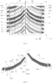
- FIG. 1 is a partial detail view of a half-MA1 pattern of the tread conforming to the invention and designated by the general reference 1-A, then three sectional views (EE, FF, GG) to illustrate the chamfers made on the trailing edges.
- FIG. 2 represents a complete MA pattern of the tread pattern, formed of two half-patterns MA1, MA2, symmetrical to each other in symmetry with respect to the equatorial plane ("C") passing through the center of the tread.
- FIG. 3 represents an unfolding of the tread in the circumferential direction (X) according to a first embodiment of the invention, with two sculpture patterns MA and MB.
- the sculpture patterns differ in their geometry (widths, cutouts, pitches, etc.).
- the MA pattern is represented with vertical hatching, and the MB pattern with wavelets.
- FIG. 4 represents an unfolding of the tread in the circumferential direction (X) according to a second embodiment of the invention, with three tread patterns, MA, MB and MC.
- the sculpture patterns differ in their geometry (widths, cutouts, pitches, etc.).
- the MC pattern is represented by black dots on a white background.
- FIG. 5 is a third embodiment of the invention. It stands out in relation to the figure 4 in that both the trailing edges and the leading edges are chamfered.
- FIG. 6 represents an MA sculpture pattern (MA1, MA2), with the leading and trailing edges chamfered.
- the figure represents the footprint of a tire of the invention inflated to its nominal pressure, and subjected to a vertical load.
- FIG. 1 represents a half-sculpture pattern referenced 1-A, and three sectional views: the sectional view EE following a sectional plane in the portion Z3, FF following a sectional plane in the portion Z2, and finally a sectional view GG following a cutting plane in portion Z1.
- the MA1 half-tread pattern is curved from an axial end of a 24G edge of the tread to the center (C) of the tread.
- the concavity of the half pattern oriented towards the center of the tread (C), determines the rolling direction of the tire designated by the reference 25.
- the half-pattern MA1 comprises three portions, a portion (Z3) contiguous to the edge 24G of the tread with an axial width of approximately one third of the total axial width of the half pattern, a central portion (Z1) of the same axial width as the portion (Z3), and an intermediate portion (Z2) contiguous to the other two portions.
- Each portion (Z1, Z2, Z3) is a volume element having an attack face which is the face whose radially outer edge first enters the contact area when of the passage of the tire on a ground.
- the edge of the radially outer leading face is hereinafter referred to as the leading edge.
- Each portion (Z1, Z2, Z3) has a face called the trailing face, the radially outer edge of which emerges last from the contact area of the tire rolling on a ground, this is the trailing edge.
- the trailing edge of each portion (Z1, Z2, Z3) is chamfered, that is to say it appears as if it had been planed to replace the projecting edge with a rectangular flat surface positioned between the rolling surface and the trailing face.
- Each portion (Z1, Z2, Z3) is ultimately provided with a chamfered edge referenced respectively (51, 52, 53).
- On the sections EE, FF, and GG are represented the chamfers of the three portions (Z1, Z2, Z3). These chamfers (51, 52, 53) are delimited by the trailing face 22, and the rolling surface 20.
- the width of a chamfer (51, 52, 53) of a portion is the normal distance between the face of leak and the edge of the chamfer belonging to the rolling surface.
- the width L.C. 3 HAS represents the width of the chamfer of the pattern MA in the central portion Z3.
- FIG 2 represents a complete sculpture pattern MA comprising two half-patterns (MA1, MA2) symmetrical with respect to the equatorial plane ("C") and offset in the circumferential direction by a length D.
- the repetition at the turn of the wheel of the sculpture pattern MA formed from half-patterns (MA1, MA2) leads to a so-called directional tread.
- the presence of a single MA tread pattern means that the tread is single pitch.
- FIG. 3 represents a first embodiment of the invention with a circumferential unfolding of the tread 10 of the tire which comprises two rows 20G and 20D of half-patterns symmetrical with respect to the equatorial plane C, and offset in the circumferential direction by a distance D.
- the sculpture patterns are separated at least in part by grooves 30 and extend radially outwards from a bottom surface 40 to the rolling surface 20 over a radial height H.
- Each pattern (MA, MB) is composed of two half-patterns (MA1, MA2) and (MB1, MB2) symmetrical with respect to the equatorial plane C, so that the pattern extends axially from a first edge 24G until 'to a second edge 24D over an axial width L.
- the pattern MA (respectively MB) is associated with a distribution pitch PA (respectively PB).
- the pitch of a pattern is the distance measured on a circumference of the running surface between a point on that pattern and the translated image of that point on the immediately following pattern.
- the trailing edges of each portion (Z1, Z2, Z3) of each pattern of the sculpture (MA, MB) are chamfered.
- the chamfers are referenced respectively (51, 52, 53) with associated widths ( L.C. 1 HAS , L.C. 2 HAS , L.C. 3 HAS ) for the MA pattern, and ( L.C. 1 B , L.C. 2 B , L.C. 3 B ) for the MB pattern.
- edges 24G, 24D of the tread 10 is meant the surfaces delimiting the boundaries between the tread 10 and the sidewalls 60. These two edges 24G, 24D are spaced apart from each other by a value W corresponding to the width of the tread 10. These two edges 24D, 24G are located at the same distance relative to a central axis C. This central axis C divides the tread 10 into two half-treads.
- the tread pattern includes an MA pattern, represented with vertical hatching and an MB pattern represented with wavelets.
- the number of tread patterns distributed in the circumferential direction results from the minimization of the rolling noise emitted by the tire as a function of the geometry of the patterns (width, pitch, cutouts, etc.).
- the tread shown in Figure 3 is called multi-pitch with two sculpture patterns MA and MB of respective steps PA and PB.
- the tread pattern comprises a third pattern MC.
- the MC pattern comprises two half-patterns (MC1, MC2) symmetrical with respect to the equatorial plane C.
- This third pattern is represented with graphic elements in the form of points on a white background.
- the step associated with this pattern is PC.
- FIG. 5 is a third embodiment of the invention. It stands out in relation to the Figure 4 in that both the trailing and leading edges are chamfered. The chamfers of the leading edges are referenced (61, 62, 63).
- FIG. 6 is an extract from the figure 5 which represents an enlargement of an MA sculpture pattern (MA1, MA2), with the leading and trailing edges chamfered.
- FIG. 7 represents a contact area of the tire inflated to its nominal pressure and crushed by the load carried.
- the dashed curve is the perimeter of the contact area which has surface AC.
- the hollows represented by the geometries with light backgrounds formed by the incisions 80 and the grooves 30, while the sculpture patterns are represented by the geometries with dark backgrounds, and represent a total surface SC.
- This figure illustrates the calculation of the surface notch rate which by definition is (AC-SC)/AC.
- the invention was more particularly studied for a passenger tire with a standardized designation, according to ETRTO (European Technical Organization for Rims and Tires), 205/65 R16 94V.
- ETRTO European Technical Organization for Rims and Tires
- a version conforming to the invention with three sculpture patterns MA, MB, and MC with respective variable pitches PA, PB, and PC was carried out.
- each sculpture pattern is associated with an elementary signal, for example sinusoidal.
- the associated signal is periodic and results from the summation of the elementary signals.
- the optimization of the initial arrangement with respect to the whirring and beating noise is carried out by carrying out simulations on different arrangements.
- the signal spectrum is analyzed in the frequency domain.
- the criteria for stopping the optimization process are linked to the amplitude of the siren and beat emergences, as well as their spread over the frequency axis.
- the total number of tread patterns is 73 on one wheel revolution, arranged according to the sequence: MB-MC -MC-MC-MA-MC-MB-MB-MA-MB-MA-MB-MA-MB-MC-MA-MA-MA-MA-MA-MB-MC-MC-MB-MA-MA-MC-MB -MA-MA-MC-MB -MC-MA-MA-MA-MB-MB-MB-MC-MC-MC-MC-MC-MB-MB-MB-MA-MA-MA-MA-MA-MB-MB-MC-MC-MC-MB-MB-MA-MA -MA-MB-MA-MC-MA-MA-MC-MA-MC-MA-MC-MA-MC-MA-MC-MA-MC-MA-MC-MA-MC-MA-MC-MA-MC-MA-MC-MC-MB-MB-MA-MA-MA-MA-MC-MA-MC-MC-MB-MB-MA-MA-MA-MA-MA-MA-MA-MA-MB-MB-MC-MB-MA-
- the circumference of the tire is equal to 2017.5 mm, and the width of the tread is 161 mm.
- the tread pattern of the manufactured tire includes 3 pattern patterns (MA, MB, MC) divided into 30 MA patterns, 18 MB patterns and finally 15 MC patterns.
- Each sculpture pattern (MA, MB, MC) is made up of two half-patterns (MA1, MA2), (MB1, MB2), and (MC1, MC2).
- the data in Table 1 are consolidated for the complete sculpture pattern (MA, MB, MC) combining the contributions of the two half-patterns.
- Each half-sculpture pattern is cut into three portions (Z1, Z2, Z3).
- We measure the average normal width of each portion by taking the normal distance between the leading and trailing edges without taking into account the chamfers.
- the average of the incision densities of the sculpture patterns (MA, MB, MC) on one revolution of the wheel is 36 mm -1 .
- the incision density of the MB carving pattern is 36 mm -1 .
- the surface notch rate is 48.6 ⁇ 0.02. Its value increases with the presence of chamfers on the trailing edges by 8% (with the trailing and leading edges 15%). Under these conditions performance is improved by the effect of contact pressure on the trailing edges.
- the volume notch rate is 30.5% ⁇ 0.004, which guarantees sufficient wet performance for an “all-season” tire.
- the following table summarizes the characteristics of chamfers. [Table 2] Chamfer width in edge portion (Z1) Chamfer width in the center portion (Z3) Chamfer width in the intermediate portion (Z2) mm mm mm MA Patterns 1.3 0.85 1.3 MB Patterns 1.5 1.5 1.5 MC Patterns 1.8 1.8 1.8
- the width of a chamfer in a portion (Z1, Z2, Z3) is the normal distance between the trailing face of the portion and the edge of the chamfer belonging to the rolling surface.
- the increase in TES has a positive effect on grip on snowy ground and also on wet ground because the chamfers are oriented favorably for the evacuation of water from the contact area. It is the same orientation as the main hollows which are widened with the presence of the chamfers.
Landscapes
- Engineering & Computer Science (AREA)
- Mechanical Engineering (AREA)
- Tires In General (AREA)
Claims (13)
- Reifen mit einem Laufstreifen (10), der dazu bestimmt ist, über eine Lauffläche (20) mit einem Boden in Kontakt zu gelangen:- wobei der Laufstreifen (10) erhabene Elemente oder Profilmuster (MA, MB) umfasst, die mindestens zum Teil voneinander durch Rillen (30) getrennt sind und sich radial nach außen von einer Bodenfläche (40) aus bis zu der Lauffläche (20) über eine radiale Höhe H von mindestens 6 mm und höchstens der radialen Höhe Hmax des Laufstreifens (10) erstrecken;- wobei jedes Profilmuster (MA, MB) zwei Teile, Halbmuster (MA1, MA2) und (MB1, MB2) genannt, umfasst, die symmetrisch in Bezug auf die durch das Zentrum des Laufstreifens (C) verlaufende Äquatorialebene sind und zueinander in Umfangsrichtung um einen Abstand D versetzt sind;- wobei jedes Halbmuster (MA1, MB1) und seine jeweilige symmetrische Entsprechung (MA2, MB2) gemäß einer axialen Richtung (YY'), von einem axialen Ende eines Rands (24G, 24D) des Laufstreifens bis zum Zentrum (C) des Laufstreifens (10) gekrümmt sind, so dass eine bevorzugte Abrollrichtung des Reifens definiert wird, und eine axiale Breite L haben;- wobei jedes Halbmuster (MA1, MB1; MA2, MB2) einen ersten seitlichen Abschnitt (Z3), der sich von einem axialen Ende des Rands des Laufstreifens (24G, 24D) aus über eine axiale Breite von höchstens einem Drittel der axialen Breite L des Halbmusters erstreckt, einen zweiten zentralen Abschnitt (Z1), der die gleiche axiale Breite wie der erste seitliche Abschnitt (Z3) hat, und einen dritten Zwischenabschnitt (Z2), der an die beiden anderen Abschnitte angrenzt, umfasst;- wobei jeder Abschnitt (Z1, Z2, Z3) jedes Halbmusters (MA1, MB1; MA2, MB2) ein Volumenelement ist, das eine Vorderseite aufweist, welche die Seite ist, deren radial äußere Kante beim Fahren des Reifens auf einem Boden als Erste in die Kontaktfläche gelangt, wobei die Kante der radial äußeren Vorderseite im Folgenden Vorderkante genannt wird;- wobei jeder Abschnitt (Z1, Z2, Z3) jedes Halbmusters (MA1, MB1; MA2, MB2) eine Hinterseite aufweist, welche die Seite ist, deren radial äußere Kante die Kontaktfläche des auf einem Boden abrollenden Reifens als Letzte verlässt, wobei die Kante der radial äußeren Hinterseite im Folgenden Hinterkante genannt wird;- wobei die Hinterkante jedes Abschnitts (Z1, Z2, Z3) jeweils ein gefastes Profil (51, 52, 53) hat, mit jeweiligen Breiten der Fasen

 - wobei die Breite einer Fase in einem Abschnitt (Z1, Z2, Z3) der normale Abstand zwischen der Hinterseite des Abschnitts und der zu der Lauffläche gehörenden Kante der Fase ist;- wobei der Laufstreifen durch eine periodische Verteilung in Umfangsrichtung eines ersten Profilmusters (MA), das aus dem Halbmuster (MA1) und seiner symmetrischen Entsprechung (MA2) gemäß einem Pitch PA gebildet wird, und eines zweiten Profilmusters (MB), das aus dem Halbmuster (MB1) und seiner symmetrischen Entsprechung (MB2) gemäß einem Pitch PB gebildet wird, erhalten wird, mit PA<PB;- wobei der Laufstreifen eine Kontaktfläche auf dem Boden AC beim Abrollen des Reifens bildet und ein Teil der Profilmuster ebenfalls eine Kontaktoberfläche SC auf der Kontaktfläche AC bildet, die einen flächenbezogenen Negativprofilanteil TES des Laufstreifens bestimmt, mit
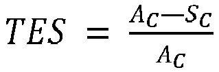 dadurch gekennzeichnet, dass in dem zweiten zentralen Abschnitt (Z1) und/oder in dem dritten Zwischenabschnitt (Z2) und/oder in dem ersten seitlichen Abschnitt (Z3) die Breiten der Fasen der Hinterkanten , wobei i von 1 bis 3 reicht, der Halbmuster(MA1, MA2) und (MB1, MB2) mit jeweiligen Pitches PA, PB mindestens eine der folgenden Ungleichungen erfüllen:a)
 b)
b) c)
c) und dass der flächenbezogene Negativprofilanteil TES mindestens 0,35 und höchstens 0,60 beträgt.
 - Reifen nach Anspruch 1, bei dem der flächenbezogene Negativprofilanteil TES größer als oder gleich 0,4 ist.
- Reifen nach einem der vorhergehenden Ansprüche von 1 bis 2, bei dem der flächenbezogene Negativprofilanteil TES größer als oder gleich 0,45 und bevorzugt größer als 0,5 ist.
- Reifen nach einem der vorhergehenden Ansprüche 1 bis 3, bei dem das Verhältnis zwischen dem Pitch PA des ersten Profilmusters (MA), das aus den Halbmustern (MA1, MA2) gebildet wird, dividiert durch den Pitch PB des zweiten Profilmusters (MB), das aus den Halbmustern (MB1, MB2) gebildet wird, PA/PB mindestens 0,80 und höchstens 0,90 beträgt.
- Reifen nach einem der Ansprüche von 1 bis 4, bei dem das Verhältnis zwischen dem Pitch PA des ersten Profilmusters (MA), das aus den Halbmustern (MA1, MA2) gebildet wird, dividiert durch den Pitch PB des zweiten Profilmusters (MB), das aus den Halbmustern (MB1, MB2) gebildet wird, PA/PB mindestens 0,85 beträgt.
- Reifen nach einem der Ansprüche 1 bis 5, bei dem die Breiten der Fasen der Vorder- und/oder Hinterkanten


 a.
a. b.
b. c.
c.
- Reifen nach einem der Ansprüche 1 bis 6, wobei der Laufstreifen ein drittes Profilmuster (MC), das aus zwei Halbmustern (MC1, MC2) gebildet wird, die in Bezug auf die Äquatorialebene (C) symmetrisch sind, mit dem Pitch PC umfasst, mit PB kleiner als PC, wobei das Verhältnis der Pitches PB/PC größer als oder gleich dem Verhältnis der Pitches PA/PB ist.
- Reifen nach einem der Ansprüche 1 bis 7, bei dem die Profilmuster eine radiale Höhe Hmax von höchstens 9 mm und bevorzugt von höchstens 7,0 mm haben.
- Reifen nach einem der Ansprüche 1 bis 8, wobei der globale volumenbezogene Negativprofilanteil TEV dem Verhältnis des Einschnittvolumens VE zum Gesamtvolumen VT des Laufstreifens entspricht, so dass TEV=VE/VT, wobei der globale volumenbezogene Negativprofilanteil TEV des Laufstreifens zwischen [20 %, 40 %] und bevorzugt zwischen [25 %, 35 %] beträgt.
- Reifen nach einem der Ansprüche 7 bis 9, wobei der Laufstreifen ein drittes Profilmuster MC mit dem Pitch PC umfasst, wobei der volumenbezogene Negativprofilanteil TEM jedes Profilmusters (MA, MB, MC) im Wesentlichen identisch ist.
- Reifen nach einem der Ansprüche 7 bis 10, wobei der Laufstreifen ein drittes Profilmuster (MC) mit dem Pitch PC umfasst, wobei der maximale Pitch der Profilmuster unter PA, PB, PC zwischen 22 mm und 40 mm, bevorzugt zwischen 23 mm und 36 mm beträgt.
- Reifen nach einem der Ansprüche 1 bis 11, wobei die Zusammensetzung des Kautschukmaterials des Laufstreifens eine Glasübergangstemperatur Tg zwischen -40 °C und -10 °C und bevorzugt zwischen -35 °C und 15 °C hat, wobei die Glasübergangstemperatur nach der Norm ASTM D 5992-96 gemessen wird, und einen komplexen dynamischen Schermodul G*, gemessen bei 60 °C, zwischen 0,5 MPa und 2 MPa und bevorzugt zwischen 0,7 MPa und 1,5 MPa hat.
- Reifen nach einem der Ansprüche 1 bis 12, bei dem mindestens 30 % der Vorder- und/oder Hinterkanten und bevorzugt mindestens 45 % der Vorder- und/oder Hinterkanten und noch bevorzugter 100 % der Vorder- und/oder Hinterkanten eine Fase haben.
Applications Claiming Priority (2)
| Application Number | Priority Date | Filing Date | Title |
|---|---|---|---|
| FR2002959A FR3108561B1 (fr) | 2020-03-26 | 2020-03-26 | Pneumatique comportant une bande de roulement optimisée en adhérence sur sol sec |
| PCT/FR2021/050487 WO2021191551A1 (fr) | 2020-03-26 | 2021-03-23 | Pneumatique comportant une bande de roulement optimisée en adhérence sur sol sec |
Publications (2)
| Publication Number | Publication Date |
|---|---|
| EP4126565A1 EP4126565A1 (de) | 2023-02-08 |
| EP4126565B1 true EP4126565B1 (de) | 2023-10-18 |
Family
ID=72709407
Family Applications (1)
| Application Number | Title | Priority Date | Filing Date |
|---|---|---|---|
| EP21717148.7A Active EP4126565B1 (de) | 2020-03-26 | 2021-03-23 | Reifen mit optimierter lauffläche in bezug auf die haftung auf trockenem boden |
Country Status (5)
| Country | Link |
|---|---|
| US (1) | US20230191847A1 (de) |
| EP (1) | EP4126565B1 (de) |
| CN (1) | CN115315361B (de) |
| FR (1) | FR3108561B1 (de) |
| WO (1) | WO2021191551A1 (de) |
Families Citing this family (2)
| Publication number | Priority date | Publication date | Assignee | Title |
|---|---|---|---|---|
| CN114630756B (zh) | 2019-11-06 | 2023-10-20 | 米其林集团总公司 | 包括胎面的轮胎 |
| JP2023134122A (ja) * | 2022-03-14 | 2023-09-27 | 住友ゴム工業株式会社 | タイヤ |
Family Cites Families (18)
| Publication number | Priority date | Publication date | Assignee | Title |
|---|---|---|---|---|
| JPS62292508A (ja) * | 1986-06-12 | 1987-12-19 | Yokohama Rubber Co Ltd:The | 雪氷路用タイヤ |
| JPH02179508A (ja) * | 1988-12-29 | 1990-07-12 | Yokohama Rubber Co Ltd:The | 空気入りタイヤ |
| KR0151660B1 (ko) * | 1995-04-24 | 1998-10-01 | 홍건희 | 타이어의 소음저감을 위한 최적의 피치배열구조 |
| JP4397494B2 (ja) * | 2000-01-26 | 2010-01-13 | 住友ゴム工業株式会社 | 空気入りタイヤ |
| EP2504179B1 (de) * | 2009-11-23 | 2014-10-22 | MICHELIN Recherche et Technique S.A. | Reifen mit seitenrille mit abkantung für verbesserte leistung auf schnee |
| KR20160052786A (ko) * | 2011-08-31 | 2016-05-12 | 미쉐린 러쉐르슈 에 떼크니크 에스.에이. | 개선된 눈길/건조 정지마찰력을 갖는 타이어 트레드 |
| US20140230980A1 (en) * | 2011-09-29 | 2014-08-21 | Michelin Recherche Et Technique S.A. | Tire with tread having improved snow and dry traction |
| KR101652558B1 (ko) * | 2012-08-22 | 2016-08-30 | 한국타이어 주식회사 | 블록 강성의 균일성이 향상된 공기입 타이어 |
| US10202006B2 (en) * | 2013-12-23 | 2019-02-12 | Pirelli Tyre S.P.A. | Tyre for vehicle wheels having improved tread pattern |
| FR3033142B1 (fr) | 2015-02-27 | 2017-02-24 | Michelin & Cie | Pneumatique avec bande de roulement directionnelle comportant une alternance de blocs et rainures incurves |
| FR3033145B1 (fr) * | 2015-02-27 | 2017-02-24 | Michelin & Cie | Pneumatique avec bande de roulement directionnelle comportant des blocs incurves pourvus de chanfreins |
| FR3044968B1 (fr) * | 2015-12-15 | 2017-12-08 | Michelin & Cie | Bande de roulement de pneumatique pour vehicule a usage agricole |
| JP6668782B2 (ja) * | 2016-01-26 | 2020-03-18 | 住友ゴム工業株式会社 | タイヤ |
| WO2017159712A1 (ja) * | 2016-03-15 | 2017-09-21 | 横浜ゴム株式会社 | 空気入りタイヤ |
| JP6414245B2 (ja) * | 2017-02-14 | 2018-10-31 | 横浜ゴム株式会社 | 空気入りタイヤ |
| DE102017203221A1 (de) * | 2017-02-28 | 2018-08-30 | Continental Reifen Deutschland Gmbh | Fahrzeugluftreifen |
| CN111386202B (zh) * | 2017-11-24 | 2022-04-05 | 米其林集团总公司 | 用于乘用车辆的轮胎 |
| CN111511584B (zh) | 2017-12-22 | 2022-04-19 | 普利司通欧洲有限公司 | 用于充气轮胎的胎面 |
-
2020
- 2020-03-26 FR FR2002959A patent/FR3108561B1/fr not_active Expired - Fee Related
-
2021
- 2021-03-23 WO PCT/FR2021/050487 patent/WO2021191551A1/fr not_active Ceased
- 2021-03-23 CN CN202180023379.6A patent/CN115315361B/zh active Active
- 2021-03-23 US US17/914,586 patent/US20230191847A1/en active Pending
- 2021-03-23 EP EP21717148.7A patent/EP4126565B1/de active Active
Also Published As
| Publication number | Publication date |
|---|---|
| CN115315361A (zh) | 2022-11-08 |
| CN115315361B (zh) | 2023-10-20 |
| FR3108561B1 (fr) | 2022-03-11 |
| EP4126565A1 (de) | 2023-02-08 |
| US20230191847A1 (en) | 2023-06-22 |
| FR3108561A1 (fr) | 2021-10-01 |
| WO2021191551A1 (fr) | 2021-09-30 |
Similar Documents
| Publication | Publication Date | Title |
|---|---|---|
| EP4003761B1 (de) | Reifen mit lauffläche | |
| EP4126566B1 (de) | Reifen mit einer lauffläche mit optimierter griffigkeit auf schneebedecktem grund | |
| EP0282765B1 (de) | Lauffläche für einen Gürtelreifen, dessen Einschnitte bogen- oder winkelförmig verlaufen | |
| EP4054860B1 (de) | Reifen mit einer lauffläche | |
| EP4003757B1 (de) | Reifen mit lauffläche | |
| EP4126565B1 (de) | Reifen mit optimierter lauffläche in bezug auf die haftung auf trockenem boden | |
| WO2021089958A1 (fr) | Pneumatique comportant une bande de roulement | |
| EP3658390B1 (de) | Reifen mit lauffläche mit einem sich entwickelnden laufflächenprofil mit lamellen | |
| EP4054858B1 (de) | Reifen mit einer lauffläche | |
| WO2017016931A1 (fr) | Bande de roulement pour pneu de poids lourd ameliorant le bruit en roulage | |
| EP4054863B1 (de) | Reifen mit einer lauffläche | |
| EP4054859B1 (de) | Reifen mit lauffläche | |
| FR3120011A1 (fr) | Pneumatique comportant une bande de roulement recreusable | |
| EP4054864B1 (de) | Reifen mit einer lauffläche | |
| EP4048531B1 (de) | Reifen mit verbessertem profil | |
| EP4048530B1 (de) | Reifen mit verbessertem profil | |
| EP3934922B1 (de) | Reifen mit laufstreifen | |
| EP4499417B1 (de) | Geräuscharmer reifen für schwerlastfahrzeug | |
| FR3127159A1 (fr) | Pneumatique avec des performances d’adhérence transversale améliorées sur sol enneigé | |
| FR3130691A1 (fr) | Pneumatique présentant un compromis de performances entre adhérence sur neige et bruit de roulement | |
| EP4399104A1 (de) | Reifen für einen stadtbus mit einer lauffläche mit verbessertem griff | |
| EP4504529A1 (de) | Reifen mit einer nachschneidenden lauffläche |
Legal Events
| Date | Code | Title | Description |
|---|---|---|---|
| STAA | Information on the status of an ep patent application or granted ep patent |
Free format text: STATUS: UNKNOWN |
|
| STAA | Information on the status of an ep patent application or granted ep patent |
Free format text: STATUS: THE INTERNATIONAL PUBLICATION HAS BEEN MADE |
|
| PUAI | Public reference made under article 153(3) epc to a published international application that has entered the european phase |
Free format text: ORIGINAL CODE: 0009012 |
|
| STAA | Information on the status of an ep patent application or granted ep patent |
Free format text: STATUS: REQUEST FOR EXAMINATION WAS MADE |
|
| 17P | Request for examination filed |
Effective date: 20221026 |
|
| AK | Designated contracting states |
Kind code of ref document: A1 Designated state(s): AL AT BE BG CH CY CZ DE DK EE ES FI FR GB GR HR HU IE IS IT LI LT LU LV MC MK MT NL NO PL PT RO RS SE SI SK SM TR |
|
| DAV | Request for validation of the european patent (deleted) | ||
| DAX | Request for extension of the european patent (deleted) | ||
| GRAP | Despatch of communication of intention to grant a patent |
Free format text: ORIGINAL CODE: EPIDOSNIGR1 |
|
| STAA | Information on the status of an ep patent application or granted ep patent |
Free format text: STATUS: GRANT OF PATENT IS INTENDED |
|
| INTG | Intention to grant announced |
Effective date: 20230721 |
|
| GRAS | Grant fee paid |
Free format text: ORIGINAL CODE: EPIDOSNIGR3 |
|
| GRAA | (expected) grant |
Free format text: ORIGINAL CODE: 0009210 |
|
| STAA | Information on the status of an ep patent application or granted ep patent |
Free format text: STATUS: THE PATENT HAS BEEN GRANTED |
|
| AK | Designated contracting states |
Kind code of ref document: B1 Designated state(s): AL AT BE BG CH CY CZ DE DK EE ES FI FR GB GR HR HU IE IS IT LI LT LU LV MC MK MT NL NO PL PT RO RS SE SI SK SM TR |
|
| REG | Reference to a national code |
Ref country code: GB Ref legal event code: FG4D Free format text: NOT ENGLISH |
|
| REG | Reference to a national code |
Ref country code: CH Ref legal event code: EP |
|
| REG | Reference to a national code |
Ref country code: DE Ref legal event code: R096 Ref document number: 602021006041 Country of ref document: DE |
|
| REG | Reference to a national code |
Ref country code: IE Ref legal event code: FG4D Free format text: LANGUAGE OF EP DOCUMENT: FRENCH |
|
| REG | Reference to a national code |
Ref country code: LT Ref legal event code: MG9D |
|
| REG | Reference to a national code |
Ref country code: NL Ref legal event code: MP Effective date: 20231018 |
|
| REG | Reference to a national code |
Ref country code: AT Ref legal event code: MK05 Ref document number: 1622118 Country of ref document: AT Kind code of ref document: T Effective date: 20231018 |
|
| PG25 | Lapsed in a contracting state [announced via postgrant information from national office to epo] |
Ref country code: NL Free format text: LAPSE BECAUSE OF FAILURE TO SUBMIT A TRANSLATION OF THE DESCRIPTION OR TO PAY THE FEE WITHIN THE PRESCRIBED TIME-LIMIT Effective date: 20231018 |
|
| PG25 | Lapsed in a contracting state [announced via postgrant information from national office to epo] |
Ref country code: GR Free format text: LAPSE BECAUSE OF FAILURE TO SUBMIT A TRANSLATION OF THE DESCRIPTION OR TO PAY THE FEE WITHIN THE PRESCRIBED TIME-LIMIT Effective date: 20240119 |
|
| PG25 | Lapsed in a contracting state [announced via postgrant information from national office to epo] |
Ref country code: IS Free format text: LAPSE BECAUSE OF FAILURE TO SUBMIT A TRANSLATION OF THE DESCRIPTION OR TO PAY THE FEE WITHIN THE PRESCRIBED TIME-LIMIT Effective date: 20240218 |
|
| PG25 | Lapsed in a contracting state [announced via postgrant information from national office to epo] |
Ref country code: LT Free format text: LAPSE BECAUSE OF FAILURE TO SUBMIT A TRANSLATION OF THE DESCRIPTION OR TO PAY THE FEE WITHIN THE PRESCRIBED TIME-LIMIT Effective date: 20231018 |
|
| PG25 | Lapsed in a contracting state [announced via postgrant information from national office to epo] |
Ref country code: AT Free format text: LAPSE BECAUSE OF FAILURE TO SUBMIT A TRANSLATION OF THE DESCRIPTION OR TO PAY THE FEE WITHIN THE PRESCRIBED TIME-LIMIT Effective date: 20231018 |
|
| PG25 | Lapsed in a contracting state [announced via postgrant information from national office to epo] |
Ref country code: ES Free format text: LAPSE BECAUSE OF FAILURE TO SUBMIT A TRANSLATION OF THE DESCRIPTION OR TO PAY THE FEE WITHIN THE PRESCRIBED TIME-LIMIT Effective date: 20231018 |
|
| PG25 | Lapsed in a contracting state [announced via postgrant information from national office to epo] |
Ref country code: LT Free format text: LAPSE BECAUSE OF FAILURE TO SUBMIT A TRANSLATION OF THE DESCRIPTION OR TO PAY THE FEE WITHIN THE PRESCRIBED TIME-LIMIT Effective date: 20231018 Ref country code: IS Free format text: LAPSE BECAUSE OF FAILURE TO SUBMIT A TRANSLATION OF THE DESCRIPTION OR TO PAY THE FEE WITHIN THE PRESCRIBED TIME-LIMIT Effective date: 20240218 Ref country code: GR Free format text: LAPSE BECAUSE OF FAILURE TO SUBMIT A TRANSLATION OF THE DESCRIPTION OR TO PAY THE FEE WITHIN THE PRESCRIBED TIME-LIMIT Effective date: 20240119 Ref country code: ES Free format text: LAPSE BECAUSE OF FAILURE TO SUBMIT A TRANSLATION OF THE DESCRIPTION OR TO PAY THE FEE WITHIN THE PRESCRIBED TIME-LIMIT Effective date: 20231018 Ref country code: BG Free format text: LAPSE BECAUSE OF FAILURE TO SUBMIT A TRANSLATION OF THE DESCRIPTION OR TO PAY THE FEE WITHIN THE PRESCRIBED TIME-LIMIT Effective date: 20240118 Ref country code: AT Free format text: LAPSE BECAUSE OF FAILURE TO SUBMIT A TRANSLATION OF THE DESCRIPTION OR TO PAY THE FEE WITHIN THE PRESCRIBED TIME-LIMIT Effective date: 20231018 Ref country code: PT Free format text: LAPSE BECAUSE OF FAILURE TO SUBMIT A TRANSLATION OF THE DESCRIPTION OR TO PAY THE FEE WITHIN THE PRESCRIBED TIME-LIMIT Effective date: 20240219 |
|
| PG25 | Lapsed in a contracting state [announced via postgrant information from national office to epo] |
Ref country code: SE Free format text: LAPSE BECAUSE OF FAILURE TO SUBMIT A TRANSLATION OF THE DESCRIPTION OR TO PAY THE FEE WITHIN THE PRESCRIBED TIME-LIMIT Effective date: 20231018 Ref country code: RS Free format text: LAPSE BECAUSE OF FAILURE TO SUBMIT A TRANSLATION OF THE DESCRIPTION OR TO PAY THE FEE WITHIN THE PRESCRIBED TIME-LIMIT Effective date: 20231018 Ref country code: PL Free format text: LAPSE BECAUSE OF FAILURE TO SUBMIT A TRANSLATION OF THE DESCRIPTION OR TO PAY THE FEE WITHIN THE PRESCRIBED TIME-LIMIT Effective date: 20231018 Ref country code: NO Free format text: LAPSE BECAUSE OF FAILURE TO SUBMIT A TRANSLATION OF THE DESCRIPTION OR TO PAY THE FEE WITHIN THE PRESCRIBED TIME-LIMIT Effective date: 20240118 Ref country code: LV Free format text: LAPSE BECAUSE OF FAILURE TO SUBMIT A TRANSLATION OF THE DESCRIPTION OR TO PAY THE FEE WITHIN THE PRESCRIBED TIME-LIMIT Effective date: 20231018 Ref country code: HR Free format text: LAPSE BECAUSE OF FAILURE TO SUBMIT A TRANSLATION OF THE DESCRIPTION OR TO PAY THE FEE WITHIN THE PRESCRIBED TIME-LIMIT Effective date: 20231018 |
|
| PG25 | Lapsed in a contracting state [announced via postgrant information from national office to epo] |
Ref country code: DK Free format text: LAPSE BECAUSE OF FAILURE TO SUBMIT A TRANSLATION OF THE DESCRIPTION OR TO PAY THE FEE WITHIN THE PRESCRIBED TIME-LIMIT Effective date: 20231018 |
|
| REG | Reference to a national code |
Ref country code: DE Ref legal event code: R097 Ref document number: 602021006041 Country of ref document: DE |
|
| PG25 | Lapsed in a contracting state [announced via postgrant information from national office to epo] |
Ref country code: CZ Free format text: LAPSE BECAUSE OF FAILURE TO SUBMIT A TRANSLATION OF THE DESCRIPTION OR TO PAY THE FEE WITHIN THE PRESCRIBED TIME-LIMIT Effective date: 20231018 |
|
| PG25 | Lapsed in a contracting state [announced via postgrant information from national office to epo] |
Ref country code: SK Free format text: LAPSE BECAUSE OF FAILURE TO SUBMIT A TRANSLATION OF THE DESCRIPTION OR TO PAY THE FEE WITHIN THE PRESCRIBED TIME-LIMIT Effective date: 20231018 |
|
| PG25 | Lapsed in a contracting state [announced via postgrant information from national office to epo] |
Ref country code: SM Free format text: LAPSE BECAUSE OF FAILURE TO SUBMIT A TRANSLATION OF THE DESCRIPTION OR TO PAY THE FEE WITHIN THE PRESCRIBED TIME-LIMIT Effective date: 20231018 Ref country code: SK Free format text: LAPSE BECAUSE OF FAILURE TO SUBMIT A TRANSLATION OF THE DESCRIPTION OR TO PAY THE FEE WITHIN THE PRESCRIBED TIME-LIMIT Effective date: 20231018 Ref country code: RO Free format text: LAPSE BECAUSE OF FAILURE TO SUBMIT A TRANSLATION OF THE DESCRIPTION OR TO PAY THE FEE WITHIN THE PRESCRIBED TIME-LIMIT Effective date: 20231018 Ref country code: IT Free format text: LAPSE BECAUSE OF FAILURE TO SUBMIT A TRANSLATION OF THE DESCRIPTION OR TO PAY THE FEE WITHIN THE PRESCRIBED TIME-LIMIT Effective date: 20231018 Ref country code: EE Free format text: LAPSE BECAUSE OF FAILURE TO SUBMIT A TRANSLATION OF THE DESCRIPTION OR TO PAY THE FEE WITHIN THE PRESCRIBED TIME-LIMIT Effective date: 20231018 Ref country code: DK Free format text: LAPSE BECAUSE OF FAILURE TO SUBMIT A TRANSLATION OF THE DESCRIPTION OR TO PAY THE FEE WITHIN THE PRESCRIBED TIME-LIMIT Effective date: 20231018 Ref country code: CZ Free format text: LAPSE BECAUSE OF FAILURE TO SUBMIT A TRANSLATION OF THE DESCRIPTION OR TO PAY THE FEE WITHIN THE PRESCRIBED TIME-LIMIT Effective date: 20231018 |
|
| PLBE | No opposition filed within time limit |
Free format text: ORIGINAL CODE: 0009261 |
|
| STAA | Information on the status of an ep patent application or granted ep patent |
Free format text: STATUS: NO OPPOSITION FILED WITHIN TIME LIMIT |
|
| 26N | No opposition filed |
Effective date: 20240719 |
|
| PG25 | Lapsed in a contracting state [announced via postgrant information from national office to epo] |
Ref country code: SI Free format text: LAPSE BECAUSE OF FAILURE TO SUBMIT A TRANSLATION OF THE DESCRIPTION OR TO PAY THE FEE WITHIN THE PRESCRIBED TIME-LIMIT Effective date: 20231018 |
|
| PG25 | Lapsed in a contracting state [announced via postgrant information from national office to epo] |
Ref country code: SI Free format text: LAPSE BECAUSE OF FAILURE TO SUBMIT A TRANSLATION OF THE DESCRIPTION OR TO PAY THE FEE WITHIN THE PRESCRIBED TIME-LIMIT Effective date: 20231018 |
|
| REG | Reference to a national code |
Ref country code: CH Ref legal event code: PL |
|
| PG25 | Lapsed in a contracting state [announced via postgrant information from national office to epo] |
Ref country code: LU Free format text: LAPSE BECAUSE OF NON-PAYMENT OF DUE FEES Effective date: 20240323 |
|
| PG25 | Lapsed in a contracting state [announced via postgrant information from national office to epo] |
Ref country code: MC Free format text: LAPSE BECAUSE OF FAILURE TO SUBMIT A TRANSLATION OF THE DESCRIPTION OR TO PAY THE FEE WITHIN THE PRESCRIBED TIME-LIMIT Effective date: 20231018 |
|
| PG25 | Lapsed in a contracting state [announced via postgrant information from national office to epo] |
Ref country code: MC Free format text: LAPSE BECAUSE OF FAILURE TO SUBMIT A TRANSLATION OF THE DESCRIPTION OR TO PAY THE FEE WITHIN THE PRESCRIBED TIME-LIMIT Effective date: 20231018 Ref country code: LU Free format text: LAPSE BECAUSE OF NON-PAYMENT OF DUE FEES Effective date: 20240323 |
|
| REG | Reference to a national code |
Ref country code: BE Ref legal event code: MM Effective date: 20240331 |
|
| PG25 | Lapsed in a contracting state [announced via postgrant information from national office to epo] |
Ref country code: BE Free format text: LAPSE BECAUSE OF NON-PAYMENT OF DUE FEES Effective date: 20240331 |
|
| PG25 | Lapsed in a contracting state [announced via postgrant information from national office to epo] |
Ref country code: IE Free format text: LAPSE BECAUSE OF NON-PAYMENT OF DUE FEES Effective date: 20240323 |
|
| PG25 | Lapsed in a contracting state [announced via postgrant information from national office to epo] |
Ref country code: IE Free format text: LAPSE BECAUSE OF NON-PAYMENT OF DUE FEES Effective date: 20240323 Ref country code: BE Free format text: LAPSE BECAUSE OF NON-PAYMENT OF DUE FEES Effective date: 20240331 Ref country code: CH Free format text: LAPSE BECAUSE OF NON-PAYMENT OF DUE FEES Effective date: 20240331 |
|
| PGFP | Annual fee paid to national office [announced via postgrant information from national office to epo] |
Ref country code: DE Payment date: 20250319 Year of fee payment: 5 |
|
| PGFP | Annual fee paid to national office [announced via postgrant information from national office to epo] |
Ref country code: FR Payment date: 20250326 Year of fee payment: 5 |
|
| PG25 | Lapsed in a contracting state [announced via postgrant information from national office to epo] |
Ref country code: CY Free format text: LAPSE BECAUSE OF FAILURE TO SUBMIT A TRANSLATION OF THE DESCRIPTION OR TO PAY THE FEE WITHIN THE PRESCRIBED TIME-LIMIT; INVALID AB INITIO Effective date: 20210323 |
|
| PG25 | Lapsed in a contracting state [announced via postgrant information from national office to epo] |
Ref country code: HU Free format text: LAPSE BECAUSE OF FAILURE TO SUBMIT A TRANSLATION OF THE DESCRIPTION OR TO PAY THE FEE WITHIN THE PRESCRIBED TIME-LIMIT; INVALID AB INITIO Effective date: 20210323 |
|
| PG25 | Lapsed in a contracting state [announced via postgrant information from national office to epo] |
Ref country code: FI Free format text: LAPSE BECAUSE OF FAILURE TO SUBMIT A TRANSLATION OF THE DESCRIPTION OR TO PAY THE FEE WITHIN THE PRESCRIBED TIME-LIMIT Effective date: 20231019 |
|
| GBPC | Gb: european patent ceased through non-payment of renewal fee |
Effective date: 20250323 |
|
| PG25 | Lapsed in a contracting state [announced via postgrant information from national office to epo] |
Ref country code: TR Free format text: LAPSE BECAUSE OF FAILURE TO SUBMIT A TRANSLATION OF THE DESCRIPTION OR TO PAY THE FEE WITHIN THE PRESCRIBED TIME-LIMIT Effective date: 20231018 |
|
| PG25 | Lapsed in a contracting state [announced via postgrant information from national office to epo] |
Ref country code: GB Free format text: LAPSE BECAUSE OF NON-PAYMENT OF DUE FEES Effective date: 20250323 |