EP4126260B1 - Ventilating firestop - Google Patents
Ventilating firestop Download PDFInfo
- Publication number
- EP4126260B1 EP4126260B1 EP21774578.5A EP21774578A EP4126260B1 EP 4126260 B1 EP4126260 B1 EP 4126260B1 EP 21774578 A EP21774578 A EP 21774578A EP 4126260 B1 EP4126260 B1 EP 4126260B1
- Authority
- EP
- European Patent Office
- Prior art keywords
- mesh
- intumescent
- firestop
- ventilating
- fire
- Prior art date
- Legal status (The legal status is an assumption and is not a legal conclusion. Google has not performed a legal analysis and makes no representation as to the accuracy of the status listed.)
- Active
Links
Images



Classifications
-
- A—HUMAN NECESSITIES
- A62—LIFE-SAVING; FIRE-FIGHTING
- A62C—FIRE-FIGHTING
- A62C2/00—Fire prevention or containment
- A62C2/06—Physical fire-barriers
- A62C2/065—Physical fire-barriers having as the main closure device materials, whose characteristics undergo an irreversible change under high temperatures, e.g. intumescent
-
- A—HUMAN NECESSITIES
- A62—LIFE-SAVING; FIRE-FIGHTING
- A62C—FIRE-FIGHTING
- A62C4/00—Flame traps allowing passage of gas but not of flame or explosion wave
Definitions
- the present invention relates to a ventilating firestop, comprising a self-supporting mesh carrying and reinforcing intumescent material.
- Intumescent-based passive vents are simple and effective firestop products. When ordinary intumescent-based vents are to stop fire within 5 min, or also to stop radiation or smoke from fire, they must be replaced by other types of fire dampers that are expensive, large or by specially manufactured intumescent vents that require straight contact surfaces and are less flexible to movements and require accurate fitting.
- Intumescent-based vents that are used for linear firestops in air cavities in facades, roof projections and roofs are prone to failure if the cladding or other construction parts bend or are consumed in a fire that create an opening for fire spread. The way that they are mounted is prone to error during fitting on site.
- Standard intumescent vents have a thick layer that takes a long time to close gaps of up to 50 mm. When the intumescent expands it can fall out. New requirements are to prevent large fires as a consequence of ordinary cavity vents failing. A requirement is that the products must retain firestopping performance even if the constructions move in fire or in wind and that they must stop fires that spread at speeds of around 3 m/min or pass a 100 mm high vent within 2s.
- US2013255893 A1 describes various forms for fire and smoke protection systems.
- the document describes a flexible fire protection which is rolled up on a roll and which is attached to a wall in front of an opening in a building.
- the flexible fire protection is in the form of a fire curtain which is rolled out to close the opening in the event of a fire.
- the flexible fire protection comprises a flexible woven material which is flame-resistant.
- the woven material has an interwoven fabric which provides improved resistance to the influence of external forces, such as from a powerful jet of water.
- the use of an intumescent is also mentioned, and it appears that the element is self-supporting.
- the solution is a closed construction that does not provide ventilation.
- US7413024 B1 shows a self-closing and plate-shaped vent which has a surrounding frame with a honeycomb-shaped structure coated with an intumescent.
- the vent When the vent is attached to a wall with an opening, the vent is normally open and allows flow of air through the opening. When exposed to heat from a fire, the intumescent material expands and closes the vent
- WO2018174720 A which corresponds to NO343232 B1 , and which describes a ventilating fire filter in a building construction comprising a three-dimensional structure of wickerwork-shaped strings covered by an intumescent.
- the three-dimensional structure is in the form of a cut-out self-supporting, frame-free piece of the structure that can be cut and flexible.
- the frame-free pieces of structure are fitted by being adapted and pushed into place in a cavity gap and are self-locking under the influence of heat.
- a common feature in known techniques is that fire insulation is not achieved until a volume is completely filled with an intumescent. Typical volumes are typically not filled until after 30s and up to 5 min, depending on the size of the air opening. It requires extensive use of elements for quenching gap and heat sink to prevent fire from passing in the period.
- a common solution in a first step is a fire gap element which stops flames before the air vent opening in a second stage is closed by an expanding intumescent which fills the entire vent and insulates the fire.
- the invention is further based on as much of the first heat as possible being absorbed in the intumescent material that forms shells. Heat that finds its way to another intumescent at the same time and thereby reduces heat uptake in the shell will delay the formation of the shell. This can happen if the intumescent for volume filling is close to that for the shell. Heat transfer by both flame radiation and convection shall not be lost to an "unnecessary" intumescent near the shell in the shell-forming phase, according to the invention.
- a further object is to provide a firestop of a spring-loaded mesh and with intumescent stripes which rapidly expands and forms a fire-insulating shell against the fire, especially in the attacking phase of the fire.
- the firestop can be used alone. Alternatively, it can have a quenching gap element for flame blocking in the open condition of the vent or a further intumescent for filling the dimensioned volume for a sufficiently long fire resistance time.
- a three-stage firestop can combine techniques where the typical step sequence is flame blocking, fire-insulating shells and a fire-insulating filled volume. Flame blocking in the open state and shell formation takes place in the attacking phase of the fire.
- a firestop vent according to the invention can be frame free, open to being cut, malleable and which, at the site of use or in the factory, can be fitted in one or more layers in hollow spaces, slits, sheets, canals built in a box or a frame.
- a firestop vent with a filling intumescent according to the invention can be designed to achieve a fixed expansion volume, self-locking by application of an expansion pocket, quenching gap, spark arrestor net, catch net for flammable droplets and, combined with a tight screen, it can stop flame radiation and smoke.
- the invention relates to a solution for ventilating firestop elements, such as air transfer grilles with fire resistance for use in buildings, where they are normally ventilated by air and block in the event of fire.
- a ventilating firestop can thus also be called a completely ventilatable firestop or fire damper.
- the invention is based on ventilating firestops with or without a quenching gap element, including an element of a self-supporting mesh applied with a semi-open intumescent pattern that forms a shell or a crust very quickly in fire heat.
- the shell-forming element is placed in the firestop so that it receives the heat as directly as possible.
- the intumescent pattern is fine meshed to provide a maximum surface area to take up the heat and provide a short distance so that an expanding intumescent mass from a thread in the pattern meets an expanding intumescent mass from the nearest thread early.
- the pattern is hereinafter also referred to as a stripe pattern. Pattern stripes may be angled arbitrary, cross each other or be in parallel to each other.
- the stripe pattern is attached to a reinforcing self-supporting mesh, typically of metal, made as a quenching gap element where it is required.
- An intumescent-based or other reactive or ablative materials that are used in the invention can, for example, be based on graphite, sodium silicate or ammonium phosphate and be characterised in that they expand at exposure to heat. Heat exposure will typically be 130 -180 °C, but high temperature activation can alternatively occur later, for example, from 300 °C upwards.
- the ventilating firestop according to the invention is preferably dimensioned so that a large and good contact surface between flames and an endothermic intumescent helps to prevent flame passage while the ventilating firestop is open, especially by extending the duration of the "quenching gap" effect when quenching gap element are used up to the time intumescent material has expanded and sealed the firestop element.
- one layer of quenching gap mesh can replace several quenching gap elements.
- quenching gap mesh that can be used in the invention is meant a mesh with openings smaller than a specific quenching gap for the combustible gas fire in intended use will be nourished.
- the ventilating firestop does not need to be fitted in any kind of frame or the like, and that the size can be adapted to the actual ventilation opening by cutting and/or cutting out to the desired dimension.
- a ventilating and yielding firestop according to the invention which, for example, is cut out of a plate will be self-supporting, i.e., it can be used as it is without a bracing or a frame to hold the intumescent material and can be attached by pressing or clamping in place by hand and/or by using clamps, screws, pins, glue, gaskets, etc. in openings. Furthermore, the yielding mesh will be able to follow the shape and/or movement of the structure and thus contribute to a more efficient firestop.
- a firestop according to the invention can be bent double or in several layers to achieve extended fire resistance time. Cut out flat firestops can be folded and adapted in layers fitted in entire building elements or in frames at the factory and can take up, for example, linear or rectangular shapes.
- Tests show that with a shield according to the invention, full fire insulation within 5 s against a typical 35 s for conventional vents is obtained in the same opening.
- the fine meshed stripes of intumescent readily have a surface and short mutual distance which, under the influence of heat, are enough for the stripes to quickly become expanded towards each other during the attacking phase of the fire for the formation of the shield.
- An intumescent located inside or outside the shield can form a coarse grid that slowly expands and fills the volume, giving fire insulation for extended time of fire resistance.
- the mesh can be formed as a flame-stopping mesh with mesh-openings of rectangular shape closing gaps.
- Said intumescent can in a first embodiment be applied to the mesh in a stripe pattern of parallel intumescent stripes.
- the intumescent can in a second embodiment be applied to the mesh in a check pattern of intumescent stripes.
- Said intumescent can be added on to the mesh as a stripe pattern carried out completely or partially in the form of close and evenly distributed dots or raised pegs or in the form of threads distributed in an air volume adjacent to the mesh.
- Mesh can be provided in a sheet form with longitudinal side edges where one or both of the longitudinally running side edges comprises a reinforcing flange.
- mesh can be produced in a sheet form or is cut into a sheet form with longitudinal side edges, where one or more side edges are folded to, or mounted on, a mounting flange.
- Mounting flanges on said side edges can be arranged for locking engagement with each other.
- the mesh can have longitudinally running side edges where a first side edge is formed with a S-shape and a second side edge is formed into a half ball shape, as the half ball shape is arranged in a locking arrangement by the insertion under the S-shape when this is fastened to a base.
- the mesh can be a malleable and spring-loaded mesh produced with spring wires for the formation of a spring-loaded effect.
- malleable and spring-loaded mesh can be produced with braided steel wires equipped with transverse spring wires for the formation of a spring-loaded effect.
- the malleable and spring-loaded mesh can also be produced with knitting steel wires equipped with transverse spring wires for the formation of a spring-loaded effect.
- the transverse spring wires can be arranged mutually spaced apart in the longitudinal direction of the mesh which is larger than a quenching gap and smaller than the maximum mesh size to prevent wastage of the expanded intumescent.
- the firestop can be comprising an expansion pocket
- the expansion pocket comprises an expandable intumescent interposed between several meshes, which pocket under expansion unfolds and become pressed against surrounding structure and edges.
- One or more of said spring wires and/or steel wires can be coated with an intumescent and be connected to a power source, said wires are arranged to be activated as heating wire(s).
- said intumescent stripes may be powder/electrode lacquered with metal, or have nano-fibred surfaces.
- said stripes of an intumescent can be extruded, glued or sprayed onto the mesh in parallel or in transverse with ventilating mesh openings between, in one or more layers.
- Said pattern of an intumescent can be attached with seams to the mesh, such as a seam of sacrificial-based polyester or cotton.
- the firestop can be cut or folded to comprise several mesh layers with inlaid, intermediate intumescent stripes between respective mesh layers with quenching gap.
- the present invention comprises a ventilating firestop which comprises a malleable and preferably spring-loaded mesh 12 with a fine mesh stripe pattern 14 of an intumescent which forms an insulating shell in the earliest phase of fire.
- the mesh 12 also includes stripes or bands of an intumescent for subsequent volume filling and fire insolation.
- the mesh 12 can be bent or rolled into a completely or approximate tubular shape so that an inner volume 22 is formed.
- the tube form can be circular, square or other shapes.
- the firestop according to the invention has a mesh with a mesh size that provides quenching gap, however, the firestop can be made with a mesh 12 without a quenching gap.
- quenching gap mesh is generally used in the description in connection with the figures, while the more generic term “mesh” is generally used in the patent claims.
- An intumescent 14 can be applied to the mesh 12 in the same way whether the mesh has a quenching gap or not.
- the quenching gap mesh 12 when this is used, has a mesh size which gives quenching gap, for example, a mesh size of between 0.8 and 8 mm.
- the mesh size i.e., the size of the openings 30 between the wires in the quenching gap net, must be less than or equal to the maximum size of the quenching gap in the particular application as determined by the gas mixture which is developed by the fire, in order to quench.
- a pattern of thin stripes, dots, pins or wires 14 of an intumescent can be applied to the mesh 12 and which can have a large surface area and a short mutual distance between them with open meshes or openings 30 between them in the plane in which the fire first strikes.
- Said intumescent can in a first embodiment be applied to the mesh in a stripe pattern of parallel intumescent stripes.
- the intumescent can in a second embodiment be applied to the mesh in a check pattern of intumescent stripes.
- the intended fire direction is upwards, and the fire is thus first noted in the lower part of the firestop 10. The effect which the fire applies is described in more detail in connection with figure 15 .
- the quenching gap mesh 12 can be made of braided or knitted spring threads 28, or the quenching gap mesh 12 can be made of braided or knitted steel threads 34 equipped with preferably spring threads 28 running in the transverse direction.
- the spring threads 28 can have a size of, for example, 1 mm.
- the steel wires 34 can also be yielding.
- the transverse spring wires 28 are usually arranged at a distance apart in the longitudinal direction of the quenching gap mesh 12 and with a mesh size which is larger than the quenching gap and smaller than maximum meshes in order to prevent a loss of expanded intumescent.
- maximum meshes is meant here the size of openings/meshes in which an expanded intumescent will be pushed through and fall down.
- the mesh size can vary with the type of intumescent.
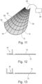
- FIGS 10 and 11 show a specific embodiment of the quenching gap mesh 12 as discussed above, while the remaining figures show the quenching gap mesh illustratively.
- one or more of the wires 28 or 34 are covered by the intumescent 14 and are connected via a wire 36 to a power source 38. On the activation of the power source 38, the wire(s) are heated up and said intumescent 14 will expand.
- the quenching gap mesh12 is initially intended to be produced in a flat form, but which can be bent into an approximately semicircular shape or in accordance with the invention into a tubular shape with a spring effect to withstand compression and at the same time react with protrusions or depressions on the surface where it is mounted.
- Figures 10 and 11 show, by way of example, that the transverse spring wires 28 substantially produce the spring effect while the longitudinal wires 34 are thinner and/or less rigid to provide a mesh which fills uneven surfaces.
- the quenching gap mesh 12 can be produced in a sheet form with longitudinal side edges 32, where one or both longitudinal side edges 32 comprises a mounting flange 16. This can be done, either the quenching gap mesh 12 is produced in a sheet form or is cut into a sheet form, in that one or more of the side edges 32 are folded to, or mounted on, a mounting flange 16.
- the mounting flange 16 can be used to fasten the firestop 10 in a cavity 22 between two building parts 20 by means of a screw, pin 18 or similar fastening means.
- the mounting flanges 16 can also be glued to the surface.
- Figure 5 shows such a fitting, where firstly the one mounting flange 16 on a first side edge 32 is attached to the base 20 by means of a screw or pin 18, and in figure 6 wherein also the second mounting flange 16 on the second side edge 32 is attached to the base 20 by means of the screw or pin 18.
- Figure 7 shows an example of a variant which is not formed into a closed tubular shape, and which is only attached to one side edge so that the other part is "free" to move.
- Mounting flanges 16 on the side edges 32 of the quenching gap mesh 12 can also be arranged to have a locking integration with each other.
- Figures 8 and 9 show an alternative embodiment of a ventilating firestop in which the quenching gap mesh 12 correspondingly has longitudinally running side edges 32, but where a first side edge is formed with an S-shape 24 and a second side edge is formed with a half ball shape 26.
- the half ball shape 26 can enter into a locking engagement by the insertion under the S-shape 24 when it is attached to the surface 20, as shown in figure 9 .
- the figures 12 and 13 further show variants of the mounting flange 16, where one or two vertical edges / folds can be folded by a folding and flange machine standing, for example, at right angles to the mesh. This makes the mounting flange 16 rigid enough to secure the quenching gap mesh 12 to hard or soft surfaces, such as wood or rock wool.
- Locking of the side edges 32 of the firestop 10 results in a fixed expansion volume 22 (as shown in fig. 14 and 15 ).
- the fixed expansion volume being similar to said cavity 22 between two building parts 20.
- Figures 14 and 15 show the difference between prior art and the invention, performed in a three-step function.
- Figure 14 shows an example of prior art where an intumescent 114 is placed in a mesh structure 112 between two building parts 20 to maximize air passage and such that the intumescent 114 can fill the entire void between the intumescent and opposite sides when all the intumescent is expanded in heat and in that it blocks against the fire (the figure to the right).
- an intumescent 14 is placed in several thin stripes which forms a fine mesh stripe pattern, in at least one plane transverse to the air direction facing the actual fire load and so closed that ventilation is good enough.
- a shield or shell barrier 40 is formed which quickly closes the vent completely in the first minutes of the attack phase (as shown in the figure in the middle). After that, sustained heat from the fire will activate the rest of the intumescent in the vent to give a lasting volume sealing during the full filling phase (as shown in the figure to the right).
- This other intumescent can also be fine meshed, but preferably coarse meshed and with wider stripes or bands. The intumescent for the formation of the shield and volume filling are separated from each other.
- the invention also works if the direction of the fire is opposite to that shown in figure 15 .
- a firestop 10 according to the invention can be comprising many fine stripes 14 of an intumescent rather than conventional thick stripes and gratings and in that the stripes are coated directly on the quenching gap mesh 12 with optimized ventilation distances in between.
- the heat of the flame and the large contact surface with an intumescent make the stripes expand very quickly to a closed shield 40 which blocks flames for many minutes.
- the heat activates an endothermic chemical process (heat consuming) in the intumescent material that takes heat from the fire gas / flames, and in that there is such a large area of intumescent surface concentrated at the outermost mesh layer that meets the flames, the process will further effectively extend the quenching gap effect such that several layers of quenching gap mesh can be avoided (several layers required in prior art).
- the wires can be extruded with heating element wire before coating on the quenching gap mesh 12, as shown in figure 11 .
- a short and adapted electrical current passage will cause the intumescent to expand and seal in a few seconds, while there is still only a little smoke in the room with the fire.
- Activation can happen from a smoke detector or manually, and a relatively small battery can be used.
- metal powder/electrode-lacquered intumescent stripes (current) or "nano hair” coatings with high heat transfer performance can be used.
- the firestop 10 can further be comprising an expansion pocket, for example, where the expansion pocket comprises an expandable intumescent interposed between several quenching gap meshes 12.
- a quenching gap mesh 12 with an intumescent stripe pattern 14 can be placed in the opening in a building structure as a strip or the like and attached as explained above.
- an externally perforated cover 42 can be used.
- the expansion pocket 44 contributes to that the firestop 10, under the influence of fire heat, can fill not only the ventilating empty space 22 in which it stands, but also fill in the expansion which can result from the building parts 20 bending in the fire and increasing the void space.
- the expansion pocket "inflates” with "limited space” for expansion. Whether the building parts are slightly compressed or give outwards, the expansion pocket will contribute to the firestop closing tightly against them when it is "inflated”.
- the expansion pocket can be in a mesh and will normally be ventilating, but not letting through an intumescent which is activated to expand in fire. Parts of the expansion pocket can be held together by threads or the like fastened between parts of the expansion pocket's mesh, where the threads can be sacrificed.
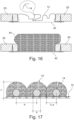
- Figure 16 shows that a ventilating expansion pocket can attach itself to a single fire sheet when it expands. Even if it is attached only from the outside, it can neither push itself out of the opening outwards nor inwards when it expands. It does not have a gasket as in ordinary vents between the frame and sheet and is mounted quickly.
- a firestop according to the invention can be produced in that an intumescent is applied in stripes 14 by extrusion.
- the stripe pattern 14 of an intumescent can alternatively be glued or sprayed on the quenching gap mesh 12 in parallel or transversely with the ventilating mesh openings 30 in between, in one or more layers. This also applies to extrusion.
- said stripes 14 of an intumescent can be fastened with seams to the quenching gap mesh 12, such as seams of sacrificial-based polyester or cotton.
- a firestop according to the invention can also be produced with several quenching gap meshes 12 with inlaid, intermediate intumescent stripes 14 between respective quenching gap meshes 12.
- the flat-produced firestops can be folded or rolled into one or more short rollers which are fitted together with, for example, two or more continuous steel wires which are cut and bent at the ends. This then constitutes an element for use in an air transfer grille, eaves vent, outer wall vent etc., where an intumescent will not glide over time. Transverse locks are secured without a throughgoing connection in the direction of fire spread and vents will be packed tightly and accurately and not bulge out in the middle.
- An example of optimal application in an air gap can be a 2 mm quenching gap mesh, but this is primarily needed only at the bottom where the fire hits.
- Other mesh can be in a spring thread of a coarser mesh, e.g., 12 mm. 12 mm is enough to hold most of the intumescent in place, but can push a suitably small amount through which seals against the connections.
- Figure 17 shows in more detail a cross-section of intumescent threads 14 at a distance a apart and with a diameter b in a fine meshed intumescent pattern on the load-bearing mesh 12.
- an expanding intumescent mass 14' meets between two wires 14 when the expanded thickness, for example, is 1 ⁇ 2 a for the formation of the shield 40.
- a can be larger than 2 b and less than 5 b , when the wire diameter b is 1-5 mm.
- the load-bearing mesh can be in metal, glass fiber or other poorly combustible material with a preferred wire diameter of 0.1-1 mm but not limited to this.
- Nearly finished expanding intumescent mass 14 is shown in dashed lines.
- An early-activated fire shield 40 including a load-bearing mesh 12, achieves at least thickness c.
- Shell thickness c can vary according to how long it shall insulate. A preferred thickness is 10-30 mm without listed articles. With listed articles in the form of a fixed quenching gap mesh, the thickness c can be less than 10 mm.
- a fire insulation time of 3-10 minutes has been achieved, but the shell according to the invention can be dimensioned to function for a longer time period. Additional fire insulation time can be achieved with the last step where more expanded intumescent fills the entire firestop.
- the fine mesh stripe pattern which forms the shield 40 and which expands rapidly can be very thin stripes, for example 2 ⁇ 2 mm, and be a short distance from each other and in all have a very large surface area per unit mass.
- the remaining stripes of intumescent mesh that fill the volume 22 can be more arbitrary and coarsely meshed, and in typical applications, bands of, for example, 35x3 mm in cross-section and with distances of 20-50 mm from each other can be used. Alternatively, the stripes for volume filling can also be fine meshed.
Landscapes
- Health & Medical Sciences (AREA)
- Public Health (AREA)
- Business, Economics & Management (AREA)
- Emergency Management (AREA)
- Building Environments (AREA)
- Glass Compositions (AREA)
- Looms (AREA)
- Percussion Or Vibration Massage (AREA)
- Fireproofing Substances (AREA)
- Fire-Extinguishing Compositions (AREA)
- Fire-Extinguishing By Fire Departments, And Fire-Extinguishing Equipment And Control Thereof (AREA)
Description
- The present invention relates to a ventilating firestop, comprising a self-supporting mesh carrying and reinforcing intumescent material.
- Intumescent-based passive vents are simple and effective firestop products. When ordinary intumescent-based vents are to stop fire within 5 min, or also to stop radiation or smoke from fire, they must be replaced by other types of fire dampers that are expensive, large or by specially manufactured intumescent vents that require straight contact surfaces and are less flexible to movements and require accurate fitting.
- Intumescent-based vents that are used for linear firestops in air cavities in facades, roof projections and roofs are prone to failure if the cladding or other construction parts bend or are consumed in a fire that create an opening for fire spread. The way that they are mounted is prone to error during fitting on site. Standard intumescent vents have a thick layer that takes a long time to close gaps of up to 50 mm. When the intumescent expands it can fall out. New requirements are to prevent large fires as a consequence of ordinary cavity vents failing. A requirement is that the products must retain firestopping performance even if the constructions move in fire or in wind and that they must stop fires that spread at speeds of around 3 m/min or pass a 100 mm high vent within 2s.
-
US2013255893 A1 describes various forms for fire and smoke protection systems. The document describes a flexible fire protection which is rolled up on a roll and which is attached to a wall in front of an opening in a building. The flexible fire protection is in the form of a fire curtain which is rolled out to close the opening in the event of a fire. Furthermore, the flexible fire protection comprises a flexible woven material which is flame-resistant. The woven material has an interwoven fabric which provides improved resistance to the influence of external forces, such as from a powerful jet of water. The use of an intumescent is also mentioned, and it appears that the element is self-supporting. However, the solution is a closed construction that does not provide ventilation. -
US7413024 B1 shows a self-closing and plate-shaped vent which has a surrounding frame with a honeycomb-shaped structure coated with an intumescent. When the vent is attached to a wall with an opening, the vent is normally open and allows flow of air through the opening. When exposed to heat from a fire, the intumescent material expands and closes the vent - Further reference is given to
WO2018174720 A , which corresponds toNO343232 B1 - A common feature in known techniques is that fire insulation is not achieved until a volume is completely filled with an intumescent. Typical volumes are typically not filled until after 30s and up to 5 min, depending on the size of the air opening. It requires extensive use of elements for quenching gap and heat sink to prevent fire from passing in the period.
- It is an object to provide a firestop device that is normally ventilating and that transforms into a full reactive firestop within a very short time when exposed to heat of fire.
- A common solution in a first step is a fire gap element which stops flames before the air vent opening in a second stage is closed by an expanding intumescent which fills the entire vent and insulates the fire. With the invention it is possible to introduce extra steps between the two mentioned, and which quickly shall form a thin shell of the first heat stress in the fire to shorten the time within which, for example, the quenching gap element is required to perform.
- The invention is further based on as much of the first heat as possible being absorbed in the intumescent material that forms shells. Heat that finds its way to another intumescent at the same time and thereby reduces heat uptake in the shell will delay the formation of the shell. This can happen if the intumescent for volume filling is close to that for the shell. Heat transfer by both flame radiation and convection shall not be lost to an "unnecessary" intumescent near the shell in the shell-forming phase, according to the invention.
- A further object is to provide a firestop of a spring-loaded mesh and with intumescent stripes which rapidly expands and forms a fire-insulating shell against the fire, especially in the attacking phase of the fire.
- The firestop can be used alone. Alternatively, it can have a quenching gap element for flame blocking in the open condition of the vent or a further intumescent for filling the dimensioned volume for a sufficiently long fire resistance time. A three-stage firestop can combine techniques where the typical step sequence is flame blocking, fire-insulating shells and a fire-insulating filled volume. Flame blocking in the open state and shell formation takes place in the attacking phase of the fire.
- A firestop vent according to the invention can be frame free, open to being cut, malleable and which, at the site of use or in the factory, can be fitted in one or more layers in hollow spaces, slits, sheets, canals built in a box or a frame.
- A firestop vent with a filling intumescent according to the invention can be designed to achieve a fixed expansion volume, self-locking by application of an expansion pocket, quenching gap, spark arrestor net, catch net for flammable droplets and, combined with a tight screen, it can stop flame radiation and smoke.
- The invention relates to a solution for ventilating firestop elements, such as air transfer grilles with fire resistance for use in buildings, where they are normally ventilated by air and block in the event of fire. A ventilating firestop can thus also be called a completely ventilatable firestop or fire damper.
- The invention is based on ventilating firestops with or without a quenching gap element, including an element of a self-supporting mesh applied with a semi-open intumescent pattern that forms a shell or a crust very quickly in fire heat. The shell-forming element is placed in the firestop so that it receives the heat as directly as possible. The intumescent pattern is fine meshed to provide a maximum surface area to take up the heat and provide a short distance so that an expanding intumescent mass from a thread in the pattern meets an expanding intumescent mass from the nearest thread early. The pattern is hereinafter also referred to as a stripe pattern. Pattern stripes may be angled arbitrary, cross each other or be in parallel to each other. The stripe pattern is attached to a reinforcing self-supporting mesh, typically of metal, made as a quenching gap element where it is required.
- An intumescent-based or other reactive or ablative materials that are used in the invention can, for example, be based on graphite, sodium silicate or ammonium phosphate and be characterised in that they expand at exposure to heat. Heat exposure will typically be 130 -180 °C, but high temperature activation can alternatively occur later, for example, from 300 °C upwards.
- The ventilating firestop according to the invention is preferably dimensioned so that a large and good contact surface between flames and an endothermic intumescent helps to prevent flame passage while the ventilating firestop is open, especially by extending the duration of the "quenching gap" effect when quenching gap element are used up to the time intumescent material has expanded and sealed the firestop element. For example, one layer of quenching gap mesh can replace several quenching gap elements.
- With quenching gap mesh that can be used in the invention is meant a mesh with openings smaller than a specific quenching gap for the combustible gas fire in intended use will be nourished.
- With self-supporting and able to be cut is meant that the ventilating firestop does not need to be fitted in any kind of frame or the like, and that the size can be adapted to the actual ventilation opening by cutting and/or cutting out to the desired dimension.
- A ventilating and yielding firestop according to the invention which, for example, is cut out of a plate will be self-supporting, i.e., it can be used as it is without a bracing or a frame to hold the intumescent material and can be attached by pressing or clamping in place by hand and/or by using clamps, screws, pins, glue, gaskets, etc. in openings. Furthermore, the yielding mesh will be able to follow the shape and/or movement of the structure and thus contribute to a more efficient firestop.
- A firestop according to the invention can be bent double or in several layers to achieve extended fire resistance time. Cut out flat firestops can be folded and adapted in layers fitted in entire building elements or in frames at the factory and can take up, for example, linear or rectangular shapes.
- The above-mentioned objects are achieved with a ventilating firestop according to
claim 1. - Tests show that with a shield according to the invention, full fire insulation within 5 s against a typical 35 s for conventional vents is obtained in the same opening.
- The fine meshed stripes of intumescent readily have a surface and short mutual distance which, under the influence of heat, are enough for the stripes to quickly become expanded towards each other during the attacking phase of the fire for the formation of the shield.
- An intumescent located inside or outside the shield can form a coarse grid that slowly expands and fills the volume, giving fire insulation for extended time of fire resistance.
- Furthermore, the mesh can be formed as a flame-stopping mesh with mesh-openings of rectangular shape closing gaps.
- Said intumescent can in a first embodiment be applied to the mesh in a stripe pattern of parallel intumescent stripes. Alternatively, the intumescent can in a second embodiment be applied to the mesh in a check pattern of intumescent stripes.
- Said intumescent can be added on to the mesh as a stripe pattern carried out completely or partially in the form of close and evenly distributed dots or raised pegs or in the form of threads distributed in an air volume adjacent to the mesh.
- Mesh can be provided in a sheet form with longitudinal side edges where one or both of the longitudinally running side edges comprises a reinforcing flange.
- Likewise, mesh can be produced in a sheet form or is cut into a sheet form with longitudinal side edges, where one or more side edges are folded to, or mounted on, a mounting flange.
- Mounting flanges on said side edges can be arranged for locking engagement with each other.
- In one variant, the mesh can have longitudinally running side edges where a first side edge is formed with a S-shape and a second side edge is formed into a half ball shape, as the half ball shape is arranged in a locking arrangement by the insertion under the S-shape when this is fastened to a base.
- The mesh can be a malleable and spring-loaded mesh produced with spring wires for the formation of a spring-loaded effect.
- Furthermore, the malleable and spring-loaded mesh can be produced with braided steel wires equipped with transverse spring wires for the formation of a spring-loaded effect.
- The malleable and spring-loaded mesh can also be produced with knitting steel wires equipped with transverse spring wires for the formation of a spring-loaded effect.
- The transverse spring wires can be arranged mutually spaced apart in the longitudinal direction of the mesh which is larger than a quenching gap and smaller than the maximum mesh size to prevent wastage of the expanded intumescent.
- Furthermore, the firestop can be comprising an expansion pocket, the expansion pocket comprises an expandable intumescent interposed between several meshes, which pocket under expansion unfolds and become pressed against surrounding structure and edges.
- One or more of said spring wires and/or steel wires can be coated with an intumescent and be connected to a power source, said wires are arranged to be activated as heating wire(s).
- In one embodiment, said intumescent stripes may be powder/electrode lacquered with metal, or have nano-fibred surfaces.
- Furthermore, said stripes of an intumescent can be extruded, glued or sprayed onto the mesh in parallel or in transverse with ventilating mesh openings between, in one or more layers.
- Said pattern of an intumescent can be attached with seams to the mesh, such as a seam of sacrificial-based polyester or cotton.
- The firestop can be cut or folded to comprise several mesh layers with inlaid, intermediate intumescent stripes between respective mesh layers with quenching gap.
- Preferred embodiments of the invention shall, in the following, be described in more detail with reference to the enclosed figures, in which:
-
Figure 1 shows a ventilating firestop according to the invention. -
Figure 2 shows the ventilating firestop shown infigure 1 fitted in an opening or a cavity in a building construction or the like. -
Figure 3 shows a variant of a ventilating firestop according to the invention. -
Figure 4 shows the ventilating firestop shown infigure 3 fitted in an opening or a cavity in a building construction or the like. -
Figure 5 shows an example of the ventilating firestop during fitting. -
Figure 6 shows the ventilating firestop after fitting. -
Figure 7 shows illustratively a ventilating firestop attached to only one side edge. -
Figure 8 shows a further variant of a ventilating firestop according to the invention. -
Figure 9 shows the ventilating firestop shown infigure 8 fitted in an opening or a cavity in a building construction or the like. -
Figure 10 shows in more detail a ventilating firestop according to the invention. -
Figure 11 shows a variant of the ventilating firestop according to the invention and which is fitted with heating wire. -
Figures 12 and 13 show illustratively variants of mounting flanges to the mesh. -
Figure 14 shows an example of a firestop according to the prior art under the influence of heat from fire. -
Figure 15 shows an example of a ventilating firestop which forms a shell according to the invention under the influence of heat from fire in the earliest phase. -
Figure 16 shows a variant of the invention where the ventilating firestop functions as an expanding pocket. -
Figure 17 shows in cross section how wires of an intumescent are placed on the mesh and expand towards each other. - As can be seen from the figures, in an embodiment example, the present invention comprises a ventilating firestop which comprises a malleable and preferably spring-loaded
mesh 12 with a finemesh stripe pattern 14 of an intumescent which forms an insulating shell in the earliest phase of fire. Themesh 12 also includes stripes or bands of an intumescent for subsequent volume filling and fire insolation. Themesh 12 can be bent or rolled into a completely or approximate tubular shape so that aninner volume 22 is formed. The tube form can be circular, square or other shapes. - The firestop according to the invention has a mesh with a mesh size that provides quenching gap, however, the firestop can be made with a
mesh 12 without a quenching gap. However, the term "quenching gap mesh" is generally used in the description in connection with the figures, while the more generic term "mesh" is generally used in the patent claims. An intumescent 14 can be applied to themesh 12 in the same way whether the mesh has a quenching gap or not. - The
quenching gap mesh 12, when this is used, has a mesh size which gives quenching gap, for example, a mesh size of between 0.8 and 8 mm. The mesh size, i.e., the size of theopenings 30 between the wires in the quenching gap net, must be less than or equal to the maximum size of the quenching gap in the particular application as determined by the gas mixture which is developed by the fire, in order to quench. - A pattern of thin stripes, dots, pins or
wires 14 of an intumescent can be applied to themesh 12 and which can have a large surface area and a short mutual distance between them with open meshes oropenings 30 between them in the plane in which the fire first strikes. Said intumescent can in a first embodiment be applied to the mesh in a stripe pattern of parallel intumescent stripes. Alternatively, the intumescent can in a second embodiment be applied to the mesh in a check pattern of intumescent stripes. Infigures 2, 4 ,5, 6 ,7 and9 the intended fire direction is upwards, and the fire is thus first noted in the lower part of thefirestop 10. The effect which the fire applies is described in more detail in connection withfigure 15 . - To produce a spring-loaded effect in the quenching gap,
mesh 12, thequenching gap mesh 12 can be made of braided or knittedspring threads 28, or thequenching gap mesh 12 can be made of braided or knittedsteel threads 34 equipped with preferablyspring threads 28 running in the transverse direction. Thespring threads 28 can have a size of, for example, 1 mm. Thesteel wires 34 can also be yielding. - The
transverse spring wires 28 are usually arranged at a distance apart in the longitudinal direction of thequenching gap mesh 12 and with a mesh size which is larger than the quenching gap and smaller than maximum meshes in order to prevent a loss of expanded intumescent. With maximum meshes is meant here the size of openings/meshes in which an expanded intumescent will be pushed through and fall down. The mesh size can vary with the type of intumescent. -
Figures 10 and11 show a specific embodiment of thequenching gap mesh 12 as discussed above, while the remaining figures show the quenching gap mesh illustratively. - In
figure 11 , one or more of thewires wire 36 to apower source 38. On the activation of thepower source 38, the wire(s) are heated up and said intumescent 14 will expand. - The quenching gap mesh12 is initially intended to be produced in a flat form, but which can be bent into an approximately semicircular shape or in accordance with the invention into a tubular shape with a spring effect to withstand compression and at the same time react with protrusions or depressions on the surface where it is mounted.
Figures 10 and11 show, by way of example, that thetransverse spring wires 28 substantially produce the spring effect while thelongitudinal wires 34 are thinner and/or less rigid to provide a mesh which fills uneven surfaces. - The
quenching gap mesh 12 can be produced in a sheet form with longitudinal side edges 32, where one or both longitudinal side edges 32 comprises a mountingflange 16. This can be done, either thequenching gap mesh 12 is produced in a sheet form or is cut into a sheet form, in that one or more of the side edges 32 are folded to, or mounted on, a mountingflange 16. - The mounting
flange 16 can be used to fasten thefirestop 10 in acavity 22 between two buildingparts 20 by means of a screw, pin 18 or similar fastening means. The mountingflanges 16 can also be glued to the surface.Figure 5 shows such a fitting, where firstly the one mountingflange 16 on afirst side edge 32 is attached to thebase 20 by means of a screw orpin 18, and infigure 6 wherein also the second mountingflange 16 on thesecond side edge 32 is attached to thebase 20 by means of the screw orpin 18. -
Figure 7 shows an example of a variant which is not formed into a closed tubular shape, and which is only attached to one side edge so that the other part is "free" to move. - Mounting
flanges 16 on the side edges 32 of thequenching gap mesh 12 can also be arranged to have a locking integration with each other. -
Figures 8 and 9 show an alternative embodiment of a ventilating firestop in which thequenching gap mesh 12 correspondingly has longitudinally running side edges 32, but where a first side edge is formed with an S-shape 24 and a second side edge is formed with ahalf ball shape 26. Thehalf ball shape 26 can enter into a locking engagement by the insertion under the S-shape 24 when it is attached to thesurface 20, as shown infigure 9 . - The
figures 12 and 13 further show variants of the mountingflange 16, where one or two vertical edges / folds can be folded by a folding and flange machine standing, for example, at right angles to the mesh. This makes the mountingflange 16 rigid enough to secure thequenching gap mesh 12 to hard or soft surfaces, such as wood or rock wool. - Locking of the side edges 32 of the
firestop 10 results in a fixed expansion volume 22 (as shown infig. 14 and 15 ). The fixed expansion volume being similar to saidcavity 22 between two buildingparts 20. -
Figures 14 and 15 show the difference between prior art and the invention, performed in a three-step function. -
Figure 14 shows an example of prior art where an intumescent 114 is placed in amesh structure 112 between two buildingparts 20 to maximize air passage and such that the intumescent 114 can fill the entire void between the intumescent and opposite sides when all the intumescent is expanded in heat and in that it blocks against the fire (the figure to the right). - According to the invention as shown in
figure 15 , an intumescent 14 is placed in several thin stripes which forms a fine mesh stripe pattern, in at least one plane transverse to the air direction facing the actual fire load and so closed that ventilation is good enough. In that the stripes expand towards each other in heat, a shield orshell barrier 40 is formed which quickly closes the vent completely in the first minutes of the attack phase (as shown in the figure in the middle). After that, sustained heat from the fire will activate the rest of the intumescent in the vent to give a lasting volume sealing during the full filling phase (as shown in the figure to the right). This other intumescent can also be fine meshed, but preferably coarse meshed and with wider stripes or bands. The intumescent for the formation of the shield and volume filling are separated from each other. - The invention also works if the direction of the fire is opposite to that shown in
figure 15 . - Thus, a
firestop 10 according to the invention can be comprising manyfine stripes 14 of an intumescent rather than conventional thick stripes and gratings and in that the stripes are coated directly on thequenching gap mesh 12 with optimized ventilation distances in between. The heat of the flame and the large contact surface with an intumescent make the stripes expand very quickly to aclosed shield 40 which blocks flames for many minutes. In the exposure phase, the heat activates an endothermic chemical process (heat consuming) in the intumescent material that takes heat from the fire gas / flames, and in that there is such a large area of intumescent surface concentrated at the outermost mesh layer that meets the flames, the process will further effectively extend the quenching gap effect such that several layers of quenching gap mesh can be avoided (several layers required in prior art). - In the next phase of the fire resistance time, more intumescent 14 expands downstream from said
shield 40, but slowly due to the heat shield to theshield 40, and it is beneficial for building up an even and compact volume of an expanded intumescent. - At the same time, it is a preferred application of the invention that it is rolled 360 degrees and into a tubular shape where the long sides are attached to each other. The effect of this is that expansion will always take place in a given
volume 22, either the environment forms the filter into an oval, into a flattened shape or into a square shape inside a suitable frame or otherwise. Because there are sealedstripes 14 with fine intumescent threads, also in the next layer the fire must pass, robust reliability is achieved. A fixed expansion volume further enables the use of an optimal amount of intumescent to ensure the longest possible fire resistance time, at the same time as any falling out of intumescent is virtually impossible. Intumescent that falls out / down leaves openings for fire and is known as one of the two biggest weaknesses with conventional solutions, where the passage of flames in the early phase is the other. - As an additional guarantee for rapid reaction also against smoke passage, the wires can be extruded with heating element wire before coating on the
quenching gap mesh 12, as shown infigure 11 . A short and adapted electrical current passage will cause the intumescent to expand and seal in a few seconds, while there is still only a little smoke in the room with the fire. Activation can happen from a smoke detector or manually, and a relatively small battery can be used. - As a further improvement of rapid expansion and less dust collection, metal powder/electrode-lacquered intumescent stripes (current) or "nano hair" coatings with high heat transfer performance can be used.
- The
firestop 10 can further be comprising an expansion pocket, for example, where the expansion pocket comprises an expandable intumescent interposed between several quenching gap meshes 12. - As shown in
figure 16 , aquenching gap mesh 12 with anintumescent stripe pattern 14 can be placed in the opening in a building structure as a strip or the like and attached as explained above. In addition, an externallyperforated cover 42 can be used. - The
expansion pocket 44 contributes to that thefirestop 10, under the influence of fire heat, can fill not only the ventilatingempty space 22 in which it stands, but also fill in the expansion which can result from thebuilding parts 20 bending in the fire and increasing the void space. The expansion pocket "inflates" with "limited space" for expansion. Whether the building parts are slightly compressed or give outwards, the expansion pocket will contribute to the firestop closing tightly against them when it is "inflated". The expansion pocket can be in a mesh and will normally be ventilating, but not letting through an intumescent which is activated to expand in fire. Parts of the expansion pocket can be held together by threads or the like fastened between parts of the expansion pocket's mesh, where the threads can be sacrificed. -
Figure 16 shows that a ventilating expansion pocket can attach itself to a single fire sheet when it expands. Even if it is attached only from the outside, it can neither push itself out of the opening outwards nor inwards when it expands. It does not have a gasket as in ordinary vents between the frame and sheet and is mounted quickly. - A firestop according to the invention can be produced in that an intumescent is applied in
stripes 14 by extrusion. - The
stripe pattern 14 of an intumescent can alternatively be glued or sprayed on thequenching gap mesh 12 in parallel or transversely with theventilating mesh openings 30 in between, in one or more layers. This also applies to extrusion. - Furthermore, said
stripes 14 of an intumescent can be fastened with seams to thequenching gap mesh 12, such as seams of sacrificial-based polyester or cotton. - A firestop according to the invention can also be produced with several quenching gap meshes 12 with inlaid, intermediate
intumescent stripes 14 between respective quenching gap meshes 12. - In use, the flat-produced firestops can be folded or rolled into one or more short rollers which are fitted together with, for example, two or more continuous steel wires which are cut and bent at the ends. This then constitutes an element for use in an air transfer grille, eaves vent, outer wall vent etc., where an intumescent will not glide over time. Transverse locks are secured without a throughgoing connection in the direction of fire spread and vents will be packed tightly and accurately and not bulge out in the middle.
- An example of optimal application in an air gap can be a 2 mm quenching gap mesh, but this is primarily needed only at the bottom where the fire hits. Other mesh can be in a spring thread of a coarser mesh, e.g., 12 mm. 12 mm is enough to hold most of the intumescent in place, but can push a suitably small amount through which seals against the connections.
-
Figure 17 shows in more detail a cross-section ofintumescent threads 14 at a distance a apart and with a diameter b in a fine meshed intumescent pattern on the load-bearing mesh 12. In the event of a fire, as shown, an expanding intumescent mass 14' meets between twowires 14 when the expanded thickness, for example, is ½ a for the formation of theshield 40. In a preferred embodiment, but not limited to, a can be larger than 2b and less than 5b, when the wire diameter b is 1-5 mm. - The load-bearing mesh can be in metal, glass fiber or other poorly combustible material with a preferred wire diameter of 0.1-1 mm but not limited to this.
- Nearly finished expanding intumescent mass 14 'is shown in dashed lines. An early-activated
fire shield 40, including a load-bearing mesh 12, achieves at least thickness c. Shell thickness c can vary according to how long it shall insulate. A preferred thickness is 10-30 mm without listed articles. With listed articles in the form of a fixed quenching gap mesh, the thickness c can be less than 10 mm. In tests of fire shells according to the invention, a fire insulation time of 3-10 minutes has been achieved, but the shell according to the invention can be dimensioned to function for a longer time period. Additional fire insulation time can be achieved with the last step where more expanded intumescent fills the entire firestop. - In a practical embodiment, the fine mesh stripe pattern which forms the
shield 40 and which expands rapidly can be very thin stripes, for example 2×2 mm, and be a short distance from each other and in all have a very large surface area per unit mass. - The remaining stripes of intumescent mesh that fill the
volume 22 can be more arbitrary and coarsely meshed, and in typical applications, bands of, for example, 35x3 mm in cross-section and with distances of 20-50 mm from each other can be used. Alternatively, the stripes for volume filling can also be fine meshed.
Claims (18)
- Ventilating firestop (10), comprisinga self-supporting mesh (12) fitted with an intumescent (14),wherebythe mesh (12) is malleable and is formed into a tubular shape forming an inner volume (22),wherein said mesh (12) is designed as a flame-stopping mesh with a mesh size that provides quenching gap,characterized in thatthe mesh (12) comprises first and second intumescent (14) applied to the mesh forming a stripe pattern of intumescent with spacing and ventilating openings (30) between the stripes,wherebysaid first intumescent (14) is on a fire load facing plane of the mesh (12) and has a fine meshed and a rapidly expandable pattern of stripes which, during a fire attack phase, expands towards each other to close said ventilating openings (30) and form a fire-insulating shield (40), andsaid second intumescent (14) is located on the mesh (12) separate from the first intumescent (14), and has a coarse meshed pattern of stripes expandable slower than those of the first intumescent (14) which, after formation of the fire-insulating shield (40), are expandable to subsequent fill up a remaining volume (22) of the firestop (10).
- Ventilating firestop (10) according to claim 1, characterised in that the finely meshed stripes (14) of intumescent have a surface and a short mutual distance which, under the influence of heat, is enough for the stripes (14) to rapid expand towards each other during the fire attack phase for the formation of the shield (40).
- Ventilating firestop (10) according to claim 1, characterised in that said intumescent (14) is applied to the mesh (12) in a stripe pattern of parallel intumescent stripes.
- Ventilating firestop (10) according to claim 1, characterised in that said intumescent (14) is applied to the mesh (12) in a check pattern of intumescent stripes.
- Ventilating firestop (10) according to claim 1, characterised in that said intumescent (14) is applied to the mesh (12) as a stripe pattern made wholly or partly in the form of closed and evenly distributed dots or upright pins or in the form of wires distributed in an air volume up to the mesh.
- Ventilating firestop according to claim 1, characterised in that the mesh (12) is produced in sheet form with longitudinal side edges (32), where one or both of the longitudinal side edges (32) comprises a mounting flange (16).
- Ventilating firestop according to claim 1, characterised in that the mesh (12) is produced in a sheet form or is cut into a sheet form with longitudinal side edges (32), and that one or more side edges (32) are folded to, or fitted onto, a mounting flange (16).
- Ventilating firestop according to claim 6 or 7, characterised in that mounting flanges (16) on said side edges (32) are arranged for locking engagement with each other.
- Ventilating firestop according to claim 1, characterised in that the mesh (12) comprises longitudinally running side edges (32), where a first side edge is formed with an S-shape (24) and a second side edge is formed with a hemispherical shape (26), the hemispherical shape (26) is arranged for locking engagement by insertion under the S-shape (24) when this is attached to a base (20).
- Ventilating firestop according to claim 1, characterised in that the mesh is a malleable and spring-loaded mesh (12) comprising spring wires (28) for formation of a spring-loaded effect.
- Ventilating firestop according to claim 10, characterised in that said malleable and spring-loaded mesh (12) is produced with braided steel wires (34) equipped with transverse-running spring wires (28) for the formation of the spring-loaded effect.
- Ventilating firestop according to claim 10, characterised in that said malleable and spring-loaded mesh (12) is produced with knitted steel wires (34) equipped with transverse-running spring wires (28) for the formation of the spring-loaded effect.
- Ventilating firestop according to claims 1 and 11 or 12, characterised in that said transverse-running spring wires (28) are arranged at a mutual distance apart in the longitudinally running direction of the mesh (12) which is larger than the quenching gap and smaller than the maximum mesh size to prevent fall out of expanded intumescent.
- Ventilating firestop according to claim 1, characterised in that said firestop comprises an expansion pocket (44), said expansion pocket comprises an expandable intumescent (14) interposed between several meshes (12).
- Ventilating firestop according to claims 10, 11 or 12, characterised in that one or more of said spring wires (28) and/or steel wires (34) are covered with an intumescent (14) and are connected to a power source (38), with said wires arranged as heating wire(s) to activate the intumescent.
- Ventilating firestop according to claim 1, characterised in that said intumescent (14) is powder/electrode lacquered with metal or is coated by nano-fiber surfaces.
- Ventilating firestop according to claim 1, characterised in that said (14) intumescent is extruded, glued, brushed or sprayed onto the mesh (12) in parallel or in intersections with ventilating mesh openings (30) between, in one or more layers.
- Ventilating firestop in accordance with claim 1, characterised in that said firestop comprises several meshes (12) with inlaid, intermediate intumescent stripes (14) between respective meshes (12) with quenching gap.
Applications Claiming Priority (2)
| Application Number | Priority Date | Filing Date | Title |
|---|---|---|---|
| NO20200349A NO345217B1 (en) | 2020-03-24 | 2020-03-24 | Ventilating fire stop |
| PCT/NO2021/050078 WO2021194352A1 (en) | 2020-03-24 | 2021-03-24 | Ventilating firestop |
Publications (4)
| Publication Number | Publication Date |
|---|---|
| EP4126260A1 EP4126260A1 (en) | 2023-02-08 |
| EP4126260A4 EP4126260A4 (en) | 2024-04-24 |
| EP4126260C0 EP4126260C0 (en) | 2025-01-22 |
| EP4126260B1 true EP4126260B1 (en) | 2025-01-22 |
Family
ID=73451196
Family Applications (1)
| Application Number | Title | Priority Date | Filing Date |
|---|---|---|---|
| EP21774578.5A Active EP4126260B1 (en) | 2020-03-24 | 2021-03-24 | Ventilating firestop |
Country Status (9)
| Country | Link |
|---|---|
| US (1) | US12239862B2 (en) |
| EP (1) | EP4126260B1 (en) |
| JP (1) | JP7723676B2 (en) |
| AU (1) | AU2021241377A1 (en) |
| CA (1) | CA3175146A1 (en) |
| ES (1) | ES3014850T3 (en) |
| IL (1) | IL296123B2 (en) |
| NO (1) | NO345217B1 (en) |
| WO (1) | WO2021194352A1 (en) |
Families Citing this family (1)
| Publication number | Priority date | Publication date | Assignee | Title |
|---|---|---|---|---|
| CN114699673B (en) * | 2022-03-30 | 2023-08-29 | 湖北宸元新材料科技有限公司 | Multilayer composite heat-insulating board and application thereof |
Family Cites Families (15)
| Publication number | Priority date | Publication date | Assignee | Title |
|---|---|---|---|---|
| GB2107183A (en) | 1981-08-14 | 1983-04-27 | Dixon International Ltd | Device for blocking a ventilation opening or duct under fire conditions |
| US5351448A (en) * | 1993-04-19 | 1994-10-04 | Balco, Inc. | Fire barrier |
| GB2331923B (en) | 1996-05-09 | 1999-07-21 | Environmental Seals Ltd | Thatched roof coverings |
| AU724332B1 (en) * | 2000-02-22 | 2000-09-14 | Nicholas Eric Tomlin | Fire and heat barrier |
| DE10060252A1 (en) | 2000-06-27 | 2002-01-10 | Illbruck Gmbh | Fire protection component (1) has metal support with through apertures separated by ribs, for example of stretch metal, achieving flow-opening barrier, which in event of fire seals against fire and smoke |
| US20090260303A1 (en) | 2002-07-05 | 2009-10-22 | Securo As | Method for fire blocking in a ventilation device and a fireblocking ventilation device |
| US7413024B1 (en) * | 2002-10-15 | 2008-08-19 | Vulcan Fire Technologies, Inc. | Self-closing vent assembly |
| JP5229985B2 (en) * | 2007-12-21 | 2013-07-03 | ニシオサプライズ株式会社 | Roof with fireproof and fireproof function and fireproof and fireproof net used therefor |
| US8151898B2 (en) * | 2009-04-23 | 2012-04-10 | Alphagen Materials Technology, Inc. | Fire suppression device and method for using |
| GB2475258A (en) * | 2009-11-11 | 2011-05-18 | Christopher John Coxon | Ventilator grille |
| GB2482318A (en) | 2010-07-29 | 2012-02-01 | Jcc Lighting Products Ltd | Intumescent covering for an electrical fitting |
| CA2801443A1 (en) | 2012-01-10 | 2013-07-10 | Stoebich Brandschutz Gmbh | Fire and smoke protection system |
| GB2533356B (en) * | 2014-12-17 | 2020-09-16 | Intumescent Systems Ltd | Ventilated cavity barriers |
| NO343232B1 (en) * | 2017-03-20 | 2018-12-10 | Scuti As | Air transfer and water draining firestop device |
| EP3517815A1 (en) * | 2018-01-24 | 2019-07-31 | HILTI Aktiengesellschaft | Assembly comprising a plurality of fire protection profiles and method for producing a fire protection profile |
-
2020
- 2020-03-24 NO NO20200349A patent/NO345217B1/en unknown
-
2021
- 2021-03-24 EP EP21774578.5A patent/EP4126260B1/en active Active
- 2021-03-24 ES ES21774578T patent/ES3014850T3/en active Active
- 2021-03-24 JP JP2022554419A patent/JP7723676B2/en active Active
- 2021-03-24 US US17/909,510 patent/US12239862B2/en active Active
- 2021-03-24 CA CA3175146A patent/CA3175146A1/en active Pending
- 2021-03-24 IL IL296123A patent/IL296123B2/en unknown
- 2021-03-24 WO PCT/NO2021/050078 patent/WO2021194352A1/en not_active Ceased
- 2021-03-24 AU AU2021241377A patent/AU2021241377A1/en active Pending
Also Published As
| Publication number | Publication date |
|---|---|
| AU2021241377A1 (en) | 2022-09-22 |
| US12239862B2 (en) | 2025-03-04 |
| EP4126260C0 (en) | 2025-01-22 |
| JP7723676B2 (en) | 2025-08-14 |
| IL296123A (en) | 2022-11-01 |
| ES3014850T3 (en) | 2025-04-25 |
| JP2023530539A (en) | 2023-07-19 |
| US20230116620A1 (en) | 2023-04-13 |
| CA3175146A1 (en) | 2021-09-30 |
| NO20200349A1 (en) | 2020-11-09 |
| IL296123B2 (en) | 2025-11-01 |
| IL296123B1 (en) | 2025-07-01 |
| EP4126260A4 (en) | 2024-04-24 |
| WO2021194352A1 (en) | 2021-09-30 |
| NO345217B1 (en) | 2020-11-09 |
| EP4126260A1 (en) | 2023-02-08 |
Similar Documents
| Publication | Publication Date | Title |
|---|---|---|
| AU2010254688B2 (en) | Method for fire blocking in a ventilation device and a fireblocking ventilation device | |
| CA2681672C (en) | Self-closing vent assembly | |
| WO2009152491A2 (en) | Device and method to provide air circulation space proximate to insulation material | |
| US12239862B2 (en) | Ventilating firestop | |
| CN110259351B (en) | Manufacturing process of high-efficiency energy-saving aluminum alloy fireproof window | |
| KR101995447B1 (en) | Composite exterior structure for construction with integral flat inorganic layer | |
| KR102083790B1 (en) | Fire Door for Heat Insulation and Heat Protection | |
| WO2018174720A1 (en) | Firestop device | |
| EP2995352B1 (en) | Corrugated fire-retardant shutter | |
| KR102140399B1 (en) | Fire prevention system of building exterior wall fire | |
| US12305384B2 (en) | Building insulation system | |
| JP2006104702A (en) | High heat insulating - combustion resisting foundation building material | |
| JP4113064B2 (en) | Wall of building, building, and fire prevention method | |
| KR200447227Y1 (en) | Sandwich composite panel | |
| EP4600432A2 (en) | A ventilated façade cladding system | |
| KR102844115B1 (en) | Fireproof Sleeve for Standing Duct | |
| CN209637001U (en) | A kind of fire prevention venting of dust explosion plate of stability and high efficiency | |
| JP4846328B2 (en) | Architectural wall body with flame barrier function, building with flame barrier function, and fire prevention method for building | |
| KR100646110B1 (en) | Insulation board for building | |
| CN216041839U (en) | Building fire-proof isolation belt | |
| US20040250487A1 (en) | Plastic ceiling board with fire extinguishing and heat insulating functions background of the invention | |
| JPH09165842A (en) | Eave soffit ventilating structure | |
| CZ14665U1 (en) | Sealing of joints and openings in fire-preventing partition building structures | |
| KR20160124358A (en) | Fireproof construction method of air conditioning duct joint of building |
Legal Events
| Date | Code | Title | Description |
|---|---|---|---|
| STAA | Information on the status of an ep patent application or granted ep patent |
Free format text: STATUS: THE INTERNATIONAL PUBLICATION HAS BEEN MADE |
|
| PUAI | Public reference made under article 153(3) epc to a published international application that has entered the european phase |
Free format text: ORIGINAL CODE: 0009012 |
|
| STAA | Information on the status of an ep patent application or granted ep patent |
Free format text: STATUS: REQUEST FOR EXAMINATION WAS MADE |
|
| 17P | Request for examination filed |
Effective date: 20221024 |
|
| AK | Designated contracting states |
Kind code of ref document: A1 Designated state(s): AL AT BE BG CH CY CZ DE DK EE ES FI FR GB GR HR HU IE IS IT LI LT LU LV MC MK MT NL NO PL PT RO RS SE SI SK SM TR |
|
| DAV | Request for validation of the european patent (deleted) | ||
| DAX | Request for extension of the european patent (deleted) | ||
| A4 | Supplementary search report drawn up and despatched |
Effective date: 20240326 |
|
| RIC1 | Information provided on ipc code assigned before grant |
Ipc: A62C 4/00 20060101ALI20240320BHEP Ipc: F16L 5/04 20060101ALI20240320BHEP Ipc: F16J 15/06 20060101ALI20240320BHEP Ipc: E04B 1/94 20060101ALI20240320BHEP Ipc: A62C 2/06 20060101AFI20240320BHEP |
|
| GRAP | Despatch of communication of intention to grant a patent |
Free format text: ORIGINAL CODE: EPIDOSNIGR1 |
|
| STAA | Information on the status of an ep patent application or granted ep patent |
Free format text: STATUS: GRANT OF PATENT IS INTENDED |
|
| INTG | Intention to grant announced |
Effective date: 20241028 |
|
| GRAS | Grant fee paid |
Free format text: ORIGINAL CODE: EPIDOSNIGR3 |
|
| GRAA | (expected) grant |
Free format text: ORIGINAL CODE: 0009210 |
|
| STAA | Information on the status of an ep patent application or granted ep patent |
Free format text: STATUS: THE PATENT HAS BEEN GRANTED |
|
| AK | Designated contracting states |
Kind code of ref document: B1 Designated state(s): AL AT BE BG CH CY CZ DE DK EE ES FI FR GB GR HR HU IE IS IT LI LT LU LV MC MK MT NL NO PL PT RO RS SE SI SK SM TR |
|
| REG | Reference to a national code |
Ref country code: GB Ref legal event code: FG4D |
|
| REG | Reference to a national code |
Ref country code: CH Ref legal event code: EP |
|
| REG | Reference to a national code |
Ref country code: IE Ref legal event code: FG4D |
|
| REG | Reference to a national code |
Ref country code: DE Ref legal event code: R096 Ref document number: 602021025147 Country of ref document: DE |
|
| U01 | Request for unitary effect filed |
Effective date: 20250212 |
|
| U07 | Unitary effect registered |
Designated state(s): AT BE BG DE DK EE FI FR IT LT LU LV MT NL PT RO SE SI Effective date: 20250218 |
|
| U20 | Renewal fee for the european patent with unitary effect paid |
Year of fee payment: 5 Effective date: 20250217 |
|
| REG | Reference to a national code |
Ref country code: ES Ref legal event code: FG2A Ref document number: 3014850 Country of ref document: ES Kind code of ref document: T3 Effective date: 20250425 |
|
| PG25 | Lapsed in a contracting state [announced via postgrant information from national office to epo] |
Ref country code: RS Free format text: LAPSE BECAUSE OF FAILURE TO SUBMIT A TRANSLATION OF THE DESCRIPTION OR TO PAY THE FEE WITHIN THE PRESCRIBED TIME-LIMIT Effective date: 20250422 |
|
| PG25 | Lapsed in a contracting state [announced via postgrant information from national office to epo] |
Ref country code: PL Free format text: LAPSE BECAUSE OF FAILURE TO SUBMIT A TRANSLATION OF THE DESCRIPTION OR TO PAY THE FEE WITHIN THE PRESCRIBED TIME-LIMIT Effective date: 20250122 |
|
| PGFP | Annual fee paid to national office [announced via postgrant information from national office to epo] |
Ref country code: ES Payment date: 20250522 Year of fee payment: 5 |
|
| PG25 | Lapsed in a contracting state [announced via postgrant information from national office to epo] |
Ref country code: IS Free format text: LAPSE BECAUSE OF FAILURE TO SUBMIT A TRANSLATION OF THE DESCRIPTION OR TO PAY THE FEE WITHIN THE PRESCRIBED TIME-LIMIT Effective date: 20250522 Ref country code: NO Free format text: LAPSE BECAUSE OF FAILURE TO SUBMIT A TRANSLATION OF THE DESCRIPTION OR TO PAY THE FEE WITHIN THE PRESCRIBED TIME-LIMIT Effective date: 20250422 |
|
| PG25 | Lapsed in a contracting state [announced via postgrant information from national office to epo] |
Ref country code: HR Free format text: LAPSE BECAUSE OF FAILURE TO SUBMIT A TRANSLATION OF THE DESCRIPTION OR TO PAY THE FEE WITHIN THE PRESCRIBED TIME-LIMIT Effective date: 20250122 |
|
| PG25 | Lapsed in a contracting state [announced via postgrant information from national office to epo] |
Ref country code: GR Free format text: LAPSE BECAUSE OF FAILURE TO SUBMIT A TRANSLATION OF THE DESCRIPTION OR TO PAY THE FEE WITHIN THE PRESCRIBED TIME-LIMIT Effective date: 20250423 |
|
| PGFP | Annual fee paid to national office [announced via postgrant information from national office to epo] |
Ref country code: CH Payment date: 20250401 Year of fee payment: 5 |
|
| PG25 | Lapsed in a contracting state [announced via postgrant information from national office to epo] |
Ref country code: SM Free format text: LAPSE BECAUSE OF FAILURE TO SUBMIT A TRANSLATION OF THE DESCRIPTION OR TO PAY THE FEE WITHIN THE PRESCRIBED TIME-LIMIT Effective date: 20250122 |
|
| PG25 | Lapsed in a contracting state [announced via postgrant information from national office to epo] |
Ref country code: MC Free format text: LAPSE BECAUSE OF FAILURE TO SUBMIT A TRANSLATION OF THE DESCRIPTION OR TO PAY THE FEE WITHIN THE PRESCRIBED TIME-LIMIT Effective date: 20250122 |
|
| PG25 | Lapsed in a contracting state [announced via postgrant information from national office to epo] |
Ref country code: CZ Free format text: LAPSE BECAUSE OF FAILURE TO SUBMIT A TRANSLATION OF THE DESCRIPTION OR TO PAY THE FEE WITHIN THE PRESCRIBED TIME-LIMIT Effective date: 20250122 |
|
| PG25 | Lapsed in a contracting state [announced via postgrant information from national office to epo] |
Ref country code: SK Free format text: LAPSE BECAUSE OF FAILURE TO SUBMIT A TRANSLATION OF THE DESCRIPTION OR TO PAY THE FEE WITHIN THE PRESCRIBED TIME-LIMIT Effective date: 20250122 |
|
| PLBE | No opposition filed within time limit |
Free format text: ORIGINAL CODE: 0009261 |
|
| STAA | Information on the status of an ep patent application or granted ep patent |
Free format text: STATUS: NO OPPOSITION FILED WITHIN TIME LIMIT |
|
| REG | Reference to a national code |
Ref country code: CH Ref legal event code: L10 Free format text: ST27 STATUS EVENT CODE: U-0-0-L10-L00 (AS PROVIDED BY THE NATIONAL OFFICE) Effective date: 20251203 |
|
| 26N | No opposition filed |
Effective date: 20251023 |
|
| U1N | Appointed representative for the unitary patent procedure changed after the registration of the unitary effect |
Representative=s name: ACAPO ONSAGERS AS; NO |
|
| PG25 | Lapsed in a contracting state [announced via postgrant information from national office to epo] |
Ref country code: IE Free format text: LAPSE BECAUSE OF NON-PAYMENT OF DUE FEES Effective date: 20250324 |
|
| U20 | Renewal fee for the european patent with unitary effect paid |
Year of fee payment: 6 Effective date: 20260205 |
|
| REG | Reference to a national code |
Ref country code: CH Ref legal event code: U11 Free format text: ST27 STATUS EVENT CODE: U-0-0-U10-U11 (AS PROVIDED BY THE NATIONAL OFFICE) Effective date: 20260401 |
|
| PGFP | Annual fee paid to national office [announced via postgrant information from national office to epo] |
Ref country code: GB Payment date: 20260213 Year of fee payment: 6 |