EP4125311A1 - Supporting device - Google Patents
Supporting device Download PDFInfo
- Publication number
- EP4125311A1 EP4125311A1 EP21205021.5A EP21205021A EP4125311A1 EP 4125311 A1 EP4125311 A1 EP 4125311A1 EP 21205021 A EP21205021 A EP 21205021A EP 4125311 A1 EP4125311 A1 EP 4125311A1
- Authority
- EP
- European Patent Office
- Prior art keywords
- mounting portion
- rack
- supporting device
- mounting
- post
- Prior art date
- Legal status (The legal status is an assumption and is not a legal conclusion. Google has not performed a legal analysis and makes no representation as to the accuracy of the status listed.)
- Granted
Links
Images






Classifications
-
- F—MECHANICAL ENGINEERING; LIGHTING; HEATING; WEAPONS; BLASTING
- F16—ENGINEERING ELEMENTS AND UNITS; GENERAL MEASURES FOR PRODUCING AND MAINTAINING EFFECTIVE FUNCTIONING OF MACHINES OR INSTALLATIONS; THERMAL INSULATION IN GENERAL
- F16B—DEVICES FOR FASTENING OR SECURING CONSTRUCTIONAL ELEMENTS OR MACHINE PARTS TOGETHER, e.g. NAILS, BOLTS, CIRCLIPS, CLAMPS, CLIPS OR WEDGES; JOINTS OR JOINTING
- F16B12/00—Jointing of furniture or the like, e.g. hidden from exterior
- F16B12/10—Jointing of furniture or the like, e.g. hidden from exterior using pegs, bolts, tenons, clamps, clips, or the like
-
- H—ELECTRICITY
- H05—ELECTRIC TECHNIQUES NOT OTHERWISE PROVIDED FOR
- H05K—PRINTED CIRCUITS; CASINGS OR CONSTRUCTIONAL DETAILS OF ELECTRIC APPARATUS; MANUFACTURE OF ASSEMBLAGES OF ELECTRICAL COMPONENTS
- H05K7/00—Constructional details common to different types of electric apparatus
- H05K7/14—Mounting supporting structure in casing or on frame or rack
- H05K7/1485—Servers; Data center rooms, e.g. 19-inch computer racks
- H05K7/1488—Cabinets therefor, e.g. chassis or racks or mechanical interfaces between blades and support structures
- H05K7/1489—Cabinets therefor, e.g. chassis or racks or mechanical interfaces between blades and support structures characterized by the mounting of blades therein, e.g. brackets, rails, trays
-
- A—HUMAN NECESSITIES
- A47—FURNITURE; DOMESTIC ARTICLES OR APPLIANCES; COFFEE MILLS; SPICE MILLS; SUCTION CLEANERS IN GENERAL
- A47B—TABLES; DESKS; OFFICE FURNITURE; CABINETS; DRAWERS; GENERAL DETAILS OF FURNITURE
- A47B96/00—Details of cabinets, racks or shelf units not covered by a single one of groups A47B43/00 - A47B95/00; General details of furniture
- A47B96/14—Bars, uprights, struts, or like supports, for cabinets, brackets, or the like
- A47B96/1408—Bars, uprights, struts, or like supports, for cabinets, brackets, or the like regularly perforated
-
- H—ELECTRICITY
- H05—ELECTRIC TECHNIQUES NOT OTHERWISE PROVIDED FOR
- H05K—PRINTED CIRCUITS; CASINGS OR CONSTRUCTIONAL DETAILS OF ELECTRIC APPARATUS; MANUFACTURE OF ASSEMBLAGES OF ELECTRICAL COMPONENTS
- H05K7/00—Constructional details common to different types of electric apparatus
- H05K7/18—Construction of rack or frame
- H05K7/183—Construction of rack or frame support rails therefor
Definitions
- the present invention relates to a supporting device and more particularly to a supporting device for use with a rack.
- US Patent No. 8,727,138 B2 discloses a slide rail that can be installed on and removed from a rack without using a tool.
- the slide rail can be used to support an object (e.g., the chassis of a piece of electronic equipment).
- the two ends of the slide rail are each provided with a latch assembly and can be mounted on a front vertical rack rail (or post) and a rear vertical rack rail (or post) of the rack via the latch assemblies respectively.
- the slide rail is mounted and locked on the rack.
- a user may manually operate the release handle of each latch assembly in order to drive the corresponding first and second latch arms from the locking position to an unlocking position (as shown in FIG. 7B of the '138 patent), thereby allowing the corresponding two pins to be moved out of the corresponding holes of the corresponding vertical rack rail respectively, and the slide rail to be subsequently detached from the rack.
- US Patent No. 8,770,528 B2 discloses a support frame assembly that can be mounted on a front post and a rear post of a rack via a front bracket and a rear bracket respectively.
- the front bracket and the rear bracket have substantially the same structural configuration.
- the front bracket includes a plurality of connection members and a fastening member, and the connection members can be longitudinally inserted into the corresponding holes of the front post respectively, with the fastening member (or more specifically a fastening portion thereof) locked to the front post by the elastic force of a resilient leg.
- the two brackets can mount the support frame assembly on the rack.
- the latch arms or fastening member disclosed in each of the foregoing two patents can be brought to a locking position by an elastic force and thus locked to a rack.
- This also means that the elastic force must be overcome in order to unlock the latch arms or fastening member from the rack (i.e., to move the latch arms or fastening member from the locking position to an unlocking portion), or the slide rail or support frame assembly cannot be detached from the rack.
- Such a design is inconvenient to the user, especially when it is required to manually remove the elastic force from both the front bracket and the rear bracket.
- the present invention relates to a supporting device for use with a rack.
- a supporting device is adapted to be mounted on a rack.
- the supporting device includes a longitudinal portion, a first mounting portion, and an elastic member.
- the first mounting portion is provided on the longitudinal portion.
- the elastic member is also provided on the longitudinal portion and is configured to be in one of a locking state and a non-locking state.
- the elastic member is provided with a second mounting portion.
- the second mounting portion is relatively far away from the first mounting portion when the elastic member is in the non-locking state, and the second mounting portion is relatively close to the first mounting portion when the elastic member is in the locking state.
- the elastic member when the first mounting portion is mounted at the first predetermined position on the rack but the force is not applied to the elastic member, the elastic member is in the non-locking state, and the second mounting portion is therefore not mounted at the second predetermined position on the rack such that the first mounting portion is allowed to move away from the first predetermined position on the rack.
- the supporting device further includes a supporting portion bent with respect to the longitudinal portion.
- the supporting portion is configured to support an object, and the object can apply the force and thereby depress the elastic member such that the elastic member is changed from the non-locking state to the locking state.
- the longitudinal portion has two opposite sides defined respectively as a first side and a second side
- the elastic member includes a connecting portion, a guiding portion, and an elastic portion provided between the connecting portion and the guiding portion.
- the connecting portion is connected to the first side of the longitudinal portion, and the elastic portion is tilted up with respect to the first side.
- the longitudinal portion includes a through hole, the through hole brings the first side and the second side into communication with each other, and the second mounting portion is provided on the elastic portion of the elastic member and is configured to be passed from the first side through the through hole to the second side.
- the supporting portion is substantially perpendicularly connected to the longitudinal portion.
- the rack includes a front post and a rear post, each including a plurality of mounting holes, and the longitudinal portion has a first end and a second end.
- the first mounting portion is adjacent to the first end of the longitudinal portion, and the longitudinal portion is further provided with an auxiliary mounting portion adjacent to the second end of the longitudinal portion.
- the first mounting portion is configured to be mounted at the first predetermined position of any of the mounting holes of the front post, and the auxiliary mounting portion is configured to be mounted at the first predetermined position of any of the mounting holes of the rear post.
- each of the first mounting portion and the auxiliary mounting portion includes a first extension section and a second extension section.
- the first extension sections are connected to the longitudinal portion.
- Each second extension section is bent with respect to the corresponding first extension section.
- Each first extension section and the corresponding second extension section jointly constitute a hook to be hung on a hole wall of any of the mounting holes of the front post or of the rear post.
- each second extension section is substantially perpendicularly connected to the corresponding first extension section.
- the first extension section of the first mounting portion is supported by the hole wall, and the second extension section of the first mounting portion is spaced apart from the front post by a transverse distance.
- the transverse distance allows the supporting device to be displaced transversely with respect to the rack.
- a supporting device is adapted to be mounted on a rack that includes a first post with a plurality of mounting holes.
- the supporting device includes a longitudinal portion, a first mounting portion, and a second mounting portion.
- the first mounting portion and the second mounting portion are both provided on the longitudinal portion.
- the first mounting portion includes a first extension section and a second extension section.
- the first extension section is connected to the longitudinal portion.
- the second extension section is bent with respect to the first extension section.
- the first extension section and the second extension section jointly constitute a hook to be hung on a hole wall of any of the mounting holes of the first post and thus located at a first predetermined position.
- the first extension section of the first mounting portion When the first mounting portion is hung on the hole wall of one of the mounting holes, the first extension section of the first mounting portion is supported by the hole wall, and the second extension section of the first mounting portion is spaced apart from the first post by a transverse distance.
- the transverse distance allows the supporting device to be displaced transversely with respect to the rack.
- the second mounting portion When the supporting device reaches a second position after being transversely displaced with respect to the rack from a first position, the second mounting portion is mounted at a second predetermined position on the rack to prevent the first mounting portion from moving away from the first predetermined position on the rack.
- the first extension section of the first mounting portion has a first transverse length
- the second mounting portion has a second transverse length less than the first transverse length
- the first mounting portion when the first mounting portion is mounted at the first predetermined position on the rack but the second mounting portion is not mounted at the second predetermined position on the rack, the first mounting portion is allowed to move away from the first predetermined position on the rack.
- the supporting device further includes a supporting portion bent with respect to the longitudinal portion.
- the supporting portion is configured to support an object, and the object can drive the supporting device into transverse displacement from the first position to the second position with respect to the rack.
- the supporting portion is substantially perpendicularly connected to the longitudinal portion.
- the rack further includes a second post with a plurality of mounting holes
- the longitudinal portion has a first end and a second end.
- the first mounting portion is adjacent to the first end of the longitudinal portion, and the longitudinal portion is further provided with an auxiliary mounting portion adjacent to the second end of the longitudinal portion.
- the first mounting portion is configured to be mounted at the first predetermined position of any of the mounting holes of the first post, and the auxiliary mounting portion is configured to be mounted at the first predetermined position of any of the mounting holes of the second post.
- the auxiliary mounting portion has substantially the same structural configuration as the first mounting portion, and the auxiliary mounting portion is configured to be hung on a hole wall of any of the mounting holes of the second post.
- the second extension section is substantially perpendicularly connected to the first extension section.
- a pair of supporting devices 22 can be used to mount an object 20 on a rack.
- the object 20 has a front portion 20a and a rear portion 20b.
- the rack has a left side and a right side that have substantially the same structural configuration.
- the left side of the rack includes at least one post, such as but not limited to a first post 24 (e.g., a front post) and a second post 26 (e.g., a rear post), wherein the first post 24 and the second post 26 have substantially the same structural configuration (for example, both the first post 24 and the second post 26 include a plurality of mounting holes 28 that are arranged at intervals along the height direction of the first and the second posts 24 and 26).
- the pair of supporting devices 22 have substantially the same structural configuration.
- Each supporting device 22 includes a longitudinal portion 30, at least one first mounting portion 32, and an elastic member 34.
- each supporting device 22 further includes a supporting portion 36 bent with respect to the corresponding longitudinal portion 30, and each supporting portion 36 is substantially perpendicularly connected to the corresponding longitudinal portion 30 and is configured to support a bottom portion of the object 20.
- the X-axis direction is defined as the longitudinal direction, the Y-axis direction as the transverse (or lateral) direction, and the Z-axis direction as the vertical direction (or the height direction of the first and the second posts 24 and 26).
- the X axis, the Y axis, and the Z axis are perpendicular to one another.
- each mounting hole 28 of the first post 24 and of the second post 26 have substantially the same structural configuration.
- Each mounting hole 28 is defined by the contours of its hole walls.
- each mounting hole 28 is defined jointly by a lower hole wall W1, an upper hole wall W2, a front hole wall W3, and a rear hole wall W4 (see FIG. 3 ).
- the structural configuration of each mounting hole 28 is not limited to that disclosed herein.
- the at least one first mounting portion 32 and the elastic member 34 of the supporting device 22 are both provided on the longitudinal portion 30.
- the elastic member 34 is provided with a second mounting portion 35, such as but not limited to a projection.
- the longitudinal portion 30 of the supporting device 22 has two opposite sides defined respectively as a first side S 1 and a second side S2.
- Each first mounting portion 32 includes a first extension section K1 and a second extension section K2.
- the first extension sections K1 are connected to the longitudinal portion 30, and the first extension sections K1 extend transversely (or laterally) beyond the second side S2.
- Each second extension section K2 is bent with respect to the corresponding first extension section K1, and in this embodiment, each second extension section K2 is substantially perpendicularly connected to the corresponding first extension section K1 by way of example.
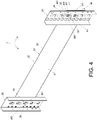
- Each first extension section K1 and the corresponding second extension section K2 jointly constitute a hook to be hung on a hole wall (e.g., the lower hole wall W1) of any of the mounting holes 28 of the first post 24 such that the corresponding first mounting portion 32 is mounted at a first predetermined position L1 on the first post 24 (see FIG. 4 ).
- the longitudinal portion 30 of the supporting device 22 has a first end 30a and a second end 30b (such as but not limited to a front end and a rear end).
- the first mounting portions 32 are adjacent to the first end 30a of the longitudinal portion 30, and the longitudinal portion 30 is further provided with at least one auxiliary mounting portion 38 adjacent to the second end 30b of the longitudinal portion 30.
- the number of the at least one auxiliary mounting portion 38 is the same as that of the at least one first mounting portion 32.
- the auxiliary mounting portions 38 have substantially the same structural configuration as the first mounting portions 32, and the way in which the auxiliary mounting portions 38 are mounted on the second post 26 is substantially the same as the way in which the first mounting portions 32 are mounted on the first post 24.
- each auxiliary mounting portion 38 is configured to be hung on a hole wall (e.g., the lower hole wall W1) of any of the mounting holes 28 of the second post 26 and thus be mounted at a first predetermined position L1 on the second post 26 (see FIG. 4 ).
- the elastic member 34 includes a connecting portion 40, a guiding portion 42, and an elastic portion 44 provided between the connecting portion 40 and the guiding portion 42.
- the connecting portion 40 is connected (e.g., fixedly connected) to a predetermined portion 43 of the first side S1 of the longitudinal portion 30.
- the elastic portion 44 is tilted up at a predetermined angle with respect to the first side S1 of the longitudinal portion 30 (see FIG. 5 ).
- the guiding portion 42 is bent with respect to the elastic portion 44 toward the first side S1 of the longitudinal portion 30 (see FIG. 5 ), and the guiding portion 42 includes, for example but not limited to, an inclined surface or a curved surface.
- the longitudinal portion 30 includes a through hole 46 that brings the first side S 1 and the second side S2 into communication with each other, the second mounting portion 35 is provided on the elastic portion 44 of the elastic member 34, and the second mounting portion 35 can be passed from the first side S 1 to the second side S2 through the through hole 46.
- the position of the second mounting portion 35 corresponds to one of the mounting holes 28 of the first post 24 (see FIG. 4 ).
- each first mounting portion 32 when each first mounting portion 32 is hung on a hole wall (e.g., the lower hole wall W1) of one of the mounting holes 28 of the first post 24, the first extension section K1 of each first mounting portion 32 is supported by the hole wall (e.g., the lower hole wall W1) of the corresponding mounting hole 28, and the second extension section K2 of each first mounting portion 32 is spaced apart from the first post 24 by a transverse distance.
- This transverse distance allows the supporting device 22 to be transversely displaced with respect to the rack (see FIG. 4 ).
- the supporting device 22 is mounted (or hung) on the first post 24 and the second post 26 of the rack via the first mounting portions 32 and the auxiliary mounting portions 38 respectively, and the elastic member 34 is in a non-locking state X1 (e.g., an unlocking state as shown in FIG. 6 ).
- a non-locking state X1 e.g., an unlocking state as shown in FIG. 6
- the elastic portion 44 of the elastic member 34 is tilted up at the predetermined angle with respect to the first side S 1 of the longitudinal portion 30 (see FIG. 6 ), and the second mounting portion 35 corresponds in position to one of the mounting holes 28 of the first post 24 (as shown in FIG.
- the object 20 can now be displaced in a predetermined direction D in order to be mounted on the supporting device 22.
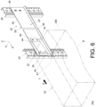
- the rear portion 20b of the object 20 will come into contact with the guiding portion 42 of the elastic member 34 (see FIG. 6 ), thus not only making it easier for a portion (e.g., a lateral side L) of the object 20 to move past the elastic member 34, but also allowing a bottom portion B of the object 20 to be partially supported by the supporting portion 36 (see FIG. 6 and FIG. 7 ).
- FIG. 6 and FIG. 7 it can be seen in FIG. 6 and FIG. 7 that when the elastic member 34 is in the non-locking state X1 (see FIG. 6 ), the second mounting portion 35 is relatively far away from the first mounting portions 32 (see FIG. 7 ); for example, the second mounting portion 35 is not aligned with the first mounting portions 32 in the vertical direction (the Z-axis direction).
- the elastic member 34 is changed from the non-locking state X1 to a locking state X2 such that the second mounting portion 35 is mounted at a second predetermined position L2 on the first post 24 of the rack (e.g., with the second mounting portion 35 inserted in one of the mounting holes 28 of the first post 24, as shown in FIG.
- the mounting gap between the second mounting portion 35 and the upper hole wall W2 of the mounting hole 28 in which the second mounting portion 35 is inserted is smaller than the extension length of the second extension section K2 of each first mounting portion 32, in order to prevent the first mounting portions 32 from moving away from their respective first predetermined positions L1 on the first post 24 of the rack (see FIG. 9 ).
- the second predetermined position L2 corresponds to the same mounting hole 28 as a first predetermined position L1. More specifically, the first predetermined positions L1 are mounting positions whereas the second predetermined position L2 is a locking position.
- the object 20 can be further pushed in the predetermined direction D in order to be mounted on the supporting device 22 completely.
- the aforesaid portion (e.g., the lateral side L) of the object 20 applies the force F and thereby depresses the elastic portion 44 of the elastic member 34 (as shown in FIG. 8 , with the elastic portion 44 of the elastic member 34 accumulating an elastic force that tends to act in the opposite direction of the force F) such that the elastic member 34 is changed from the non-locking state X1 to the locking state X2.
- the second mounting portion 35 ends up mounted at the second predetermined position L2 on the first post 24 of the rack (e.g., inserted in the corresponding mounting hole 28 of the first post 24, as shown in FIG.
- the elastic portion 44 of the elastic member 34 releases the accumulated elastic force and returns from the locking state X2 to the non-locking state X1 such that the second mounting portion 35 is no longer mounted at the second predetermined position L2 on the first post 24 of the rack (e.g., the second mounting portion 35 is moved away from the corresponding mounting hole 28 of the first post 24 of the rack), thereby allowing the first mounting portions 32 to move away from their respective first predetermined positions L1 on the first post 24 of the rack in the height direction H and hence from the corresponding mounting holes
- FIG. 10 depicts the supporting device 200 according to another embodiment of the present invention.
- the supporting device 200 in this embodiment is different from the supporting device 22 in the previous embodiment mainly in that the supporting device 200 does not include the elastic member 34 in the previous embodiment (i.e., the second mounting portion 204 of the supporting device 200 is not provided on the elastic member 34). More specifically, both the first mounting portion 202 and the second mounting portion 204 of the supporting device 200 are provided directly on the longitudinal portion 206.
- the first mounting portion 202 includes a first extension section K1' and a second extension section K2'.
- the first extension section K1' is connected to the longitudinal portion 206, and the first extension section K1' extends transversely (or laterally) beyond the second side S2 of the longitudinal portion 206.
- the second extension section K2' is bent with respect to the first extension section K1', and in this embodiment, the second extension section K2' is substantially perpendicularly connected to the first extension section K1' by way of example.
- the second mounting portion 204 extends transversely (or laterally) beyond the second side S2 of the longitudinal portion 206 too and is a projection by way of example.
- the first extension section K1' of the first mounting portion 202 has a first transverse length T1 extending from the second side S2 of the longitudinal portion 206, and the second mounting portion 204 has a second transverse length T2 extending from the second side S2 of the longitudinal portion 206.
- the second transverse length T2 is less than the first transverse length T1.
- the first extension section K1' and the second extension section K2' of the first mounting portion 202 jointly constitute a hook to be hung on a hole wall (e.g., the lower hole wall W1) of any of the mounting holes 28 of the first post 24 of the rack such that the first mounting portion 202 is mounted at a first predetermined position L1 on the first post 24.
- a hole wall e.g., the lower hole wall W1 of any of the mounting holes 28 of the first post 24 of the rack such that the first mounting portion 202 is mounted at a first predetermined position L1 on the first post 24.
- the first extension section K1' of the first mounting portion 202 is supported by the hole wall (e.g., the lower hole wall W1), and the second extension section K2' of the first mounting portion 202 is spaced apart from the first post 24 by a transverse distance T (see FIG. 12 ).
- the transverse distance T allows the supporting device 200 to be transversely displaced with respect to the rack.
- the supporting device 200 can be at a first position P1 (see FIG. 11 ) or a second position P2 (see FIG. 12 ) with respect to the rack.
- the second mounting portion 204 is mounted at a second predetermined position L2 on the first post 24 (e.g., the second mounting portion 204 is inserted in another mounting hole 28, say mounting hole 28', of the first post 24, as shown in FIG. 12 ) to prevent the first mounting portion 202 from moving away from the first predetermined position L1 on the rack (e.g., to prevent the first mounting portion 202 from moving away from the lower hole wall W1 of the corresponding mounting hole 28 of the first post 24 in the height direction H, as shown in FIG. 12 ); consequently, the supporting device 200 is locked to the rack.
- the first predetermined position L1 and the second predetermined position L2 correspond to different mounting holes 28 respectively.
- the first predetermined position L1 is a mounting position whereas the second predetermined position L2 is a locking position.
- the mounting gap between the second mounting portion 204 and the upper hole wall W2 of the mounting hole 28' is smaller than the extension length of the second extension section K2' of the first mounting portion 202, in order to prevent the first mounting portion 202 from moving away from the first predetermined position L1 on the first post 24 of the rack (see FIG. 12 ).
- the first mounting portion 202 is mounted at the first predetermined position L1 on the first post 24 of the rack (e.g., when the first mounting portion 202 is hung on the lower hole wall W1 of the corresponding mounting hole 28 of the first post 24) but the second mounting portion 204 is not mounted at the second predetermined position L2 on the rack (e.g., when the second mounting portion 204 has yet to be inserted in the mounting hole 28' of the first post 24, as shown in FIG. 11 ), the first mounting portion 202 is allowed to move away from the first predetermined position L1 on the first post 24 of the rack.
- the supporting portion 208 of the supporting device 200 is configured to support the object 20, and the object 20 can drive the supporting device 200 into transverse displacement from the first position P1 to the second position P2 with respect to the rack.
- a portion e.g., the lateral side L
- the supporting device 200 pushes the supporting device 200 and thereby displaces the supporting device 200 transversely from the first position P1 (see FIG. 11 ) to the second position P2 (see FIG. 12 ) with respect to the rack.
- one of the longitudinal portion 206 and the object 20 is provided with a guiding feature 207 such as an inclined surface or a curved surface (as shown in FIG. 10 and FIG. 11 ).
- the guiding feature 207 is adjacent to the first end 206a of the longitudinal portion 206 so that while the object 20 is being displaced in the predetermined direction D in order to be mounted on the supporting device 200, the guiding feature 207 makes it easier for the object 20 to push, and thereby transversely displace, the supporting device 200 from the first position P1 (see FIG. 11 ) to the second position P2 (see FIG. 12 ).
- the auxiliary mounting portion 210 is configured to be hung on a hole wall (e.g., the lower hole wall W1) of any of the mounting holes 28 of the post 26 so as to be mounted at a first predetermined position L1 on the second post 26 (as shown in FIG. 11 and FIG. 12 ).
- a hole wall e.g., the lower hole wall W1 of any of the mounting holes 28 of the post 26 so as to be mounted at a first predetermined position L1 on the second post 26 (as shown in FIG. 11 and FIG. 12 ).
- the supporting device 22/200 of the present invention has the following features:
Landscapes
- Engineering & Computer Science (AREA)
- General Engineering & Computer Science (AREA)
- Microelectronics & Electronic Packaging (AREA)
- Mechanical Engineering (AREA)
- Computer Hardware Design (AREA)
- Drawers Of Furniture (AREA)
- Assembled Shelves (AREA)
- Warehouses Or Storage Devices (AREA)
Abstract
Description
- The present invention relates to a supporting device and more particularly to a supporting device for use with a rack.
-
US Patent No. 8,727,138 B2 discloses a slide rail that can be installed on and removed from a rack without using a tool. The slide rail can be used to support an object (e.g., the chassis of a piece of electronic equipment). The two ends of the slide rail are each provided with a latch assembly and can be mounted on a front vertical rack rail (or post) and a rear vertical rack rail (or post) of the rack via the latch assemblies respectively. When the two longitudinal pins of each latch assembly are inserted respectively into the corresponding holes of the corresponding vertical rack rail, and the first latch arm and the second latch arm of each latch assembly are at a locking position due to the elastic force of an elastic member and thus locked to the corresponding vertical rack rail (as shown inFIG. 7A of the '138 patent), the slide rail is mounted and locked on the rack. A user may manually operate the release handle of each latch assembly in order to drive the corresponding first and second latch arms from the locking position to an unlocking position (as shown inFIG. 7B of the '138 patent), thereby allowing the corresponding two pins to be moved out of the corresponding holes of the corresponding vertical rack rail respectively, and the slide rail to be subsequently detached from the rack. -
US Patent No. 8,770,528 B2 discloses a support frame assembly that can be mounted on a front post and a rear post of a rack via a front bracket and a rear bracket respectively. The front bracket and the rear bracket have substantially the same structural configuration. For example, the front bracket includes a plurality of connection members and a fastening member, and the connection members can be longitudinally inserted into the corresponding holes of the front post respectively, with the fastening member (or more specifically a fastening portion thereof) locked to the front post by the elastic force of a resilient leg. Thus, the two brackets can mount the support frame assembly on the rack. - It can be known from the above that the latch arms or fastening member disclosed in each of the foregoing two patents can be brought to a locking position by an elastic force and thus locked to a rack. This also means that the elastic force must be overcome in order to unlock the latch arms or fastening member from the rack (i.e., to move the latch arms or fastening member from the locking position to an unlocking portion), or the slide rail or support frame assembly cannot be detached from the rack. Such a design, however, is inconvenient to the user, especially when it is required to manually remove the elastic force from both the front bracket and the rear bracket.
- In view of the evolution of market demands and rack designs, it is worthwhile to develop a different product from those described above.
- The present invention relates to a supporting device for use with a rack.
- The objective of the invention is achieved by the subject-matter of the independent claims. Advantageous embodiments are disclosed by the dependent claims.
- According to one aspect of the present invention, a supporting device is adapted to be mounted on a rack. The supporting device includes a longitudinal portion, a first mounting portion, and an elastic member. The first mounting portion is provided on the longitudinal portion. The elastic member is also provided on the longitudinal portion and is configured to be in one of a locking state and a non-locking state. The elastic member is provided with a second mounting portion. When the first mounting portion is mounted at a first predetermined position on the rack and a force is applied to the elastic member, the elastic member is changed from the non-locking state to the locking state such that the second mounting portion is mounted at a second predetermined position on the rack to prevent the first mounting portion from moving away from the first predetermined position on the rack.
- The second mounting portion is relatively far away from the first mounting portion when the elastic member is in the non-locking state, and the second mounting portion is relatively close to the first mounting portion when the elastic member is in the locking state.
- Preferably, when the first mounting portion is mounted at the first predetermined position on the rack but the force is not applied to the elastic member, the elastic member is in the non-locking state, and the second mounting portion is therefore not mounted at the second predetermined position on the rack such that the first mounting portion is allowed to move away from the first predetermined position on the rack.
- Preferably, the supporting device further includes a supporting portion bent with respect to the longitudinal portion. The supporting portion is configured to support an object, and the object can apply the force and thereby depress the elastic member such that the elastic member is changed from the non-locking state to the locking state.
- Preferably, the longitudinal portion has two opposite sides defined respectively as a first side and a second side, and the elastic member includes a connecting portion, a guiding portion, and an elastic portion provided between the connecting portion and the guiding portion. The connecting portion is connected to the first side of the longitudinal portion, and the elastic portion is tilted up with respect to the first side.
- Preferably, the longitudinal portion includes a through hole, the through hole brings the first side and the second side into communication with each other, and the second mounting portion is provided on the elastic portion of the elastic member and is configured to be passed from the first side through the through hole to the second side.
- Preferably, the supporting portion is substantially perpendicularly connected to the longitudinal portion.
- Preferably, the rack includes a front post and a rear post, each including a plurality of mounting holes, and the longitudinal portion has a first end and a second end. The first mounting portion is adjacent to the first end of the longitudinal portion, and the longitudinal portion is further provided with an auxiliary mounting portion adjacent to the second end of the longitudinal portion. The first mounting portion is configured to be mounted at the first predetermined position of any of the mounting holes of the front post, and the auxiliary mounting portion is configured to be mounted at the first predetermined position of any of the mounting holes of the rear post.
- Preferably, each of the first mounting portion and the auxiliary mounting portion includes a first extension section and a second extension section. The first extension sections are connected to the longitudinal portion. Each second extension section is bent with respect to the corresponding first extension section. Each first extension section and the corresponding second extension section jointly constitute a hook to be hung on a hole wall of any of the mounting holes of the front post or of the rear post.
- Preferably, each second extension section is substantially perpendicularly connected to the corresponding first extension section.
- Preferably, when the first mounting portion is hung on the hole wall of one of the mounting holes, the first extension section of the first mounting portion is supported by the hole wall, and the second extension section of the first mounting portion is spaced apart from the front post by a transverse distance. The transverse distance allows the supporting device to be displaced transversely with respect to the rack.
- According to yet another aspect of the present invention, a supporting device is adapted to be mounted on a rack that includes a first post with a plurality of mounting holes. The supporting device includes a longitudinal portion, a first mounting portion, and a second mounting portion. The first mounting portion and the second mounting portion are both provided on the longitudinal portion. The first mounting portion includes a first extension section and a second extension section. The first extension section is connected to the longitudinal portion. The second extension section is bent with respect to the first extension section. The first extension section and the second extension section jointly constitute a hook to be hung on a hole wall of any of the mounting holes of the first post and thus located at a first predetermined position. When the first mounting portion is hung on the hole wall of one of the mounting holes, the first extension section of the first mounting portion is supported by the hole wall, and the second extension section of the first mounting portion is spaced apart from the first post by a transverse distance. The transverse distance allows the supporting device to be displaced transversely with respect to the rack. When the supporting device reaches a second position after being transversely displaced with respect to the rack from a first position, the second mounting portion is mounted at a second predetermined position on the rack to prevent the first mounting portion from moving away from the first predetermined position on the rack.
- Preferably, the first extension section of the first mounting portion has a first transverse length, and the second mounting portion has a second transverse length less than the first transverse length.
- Preferably, when the first mounting portion is mounted at the first predetermined position on the rack but the second mounting portion is not mounted at the second predetermined position on the rack, the first mounting portion is allowed to move away from the first predetermined position on the rack.
- Preferably, the supporting device further includes a supporting portion bent with respect to the longitudinal portion. The supporting portion is configured to support an object, and the object can drive the supporting device into transverse displacement from the first position to the second position with respect to the rack.
- Preferably, the supporting portion is substantially perpendicularly connected to the longitudinal portion.
- Preferably, the rack further includes a second post with a plurality of mounting holes, and the longitudinal portion has a first end and a second end. The first mounting portion is adjacent to the first end of the longitudinal portion, and the longitudinal portion is further provided with an auxiliary mounting portion adjacent to the second end of the longitudinal portion. The first mounting portion is configured to be mounted at the first predetermined position of any of the mounting holes of the first post, and the auxiliary mounting portion is configured to be mounted at the first predetermined position of any of the mounting holes of the second post.
- Preferably, the auxiliary mounting portion has substantially the same structural configuration as the first mounting portion, and the auxiliary mounting portion is configured to be hung on a hole wall of any of the mounting holes of the second post.
- Preferably, the second extension section is substantially perpendicularly connected to the first extension section.
-
-
FIG. 1 is a perspective view showing an object mounted on a rack via a pair of supporting devices according to an embodiment of the present invention; -
FIG. 2 is a perspective view showing that the pair of supporting devices according to the embodiment of the present invention are mounted on the rack; -
FIG. 3 is an exploded perspective view of one of the supporting devices according to the embodiment of the present invention, with the supporting device detached from the rack; -
FIG. 4 shows that supporting device according to the embodiment of the present invention is mounted on the rack; -
FIG. 5 shows the supporting device and the rack according to the embodiment of the present invention from another viewing angle; -
FIG. 6 shows from a first viewing angle that the object can be displaced in a predetermined direction in order to be mounted on the supporting device, which is mounted on the rack, according to the embodiment of the present invention; -
FIG. 7 shows from a second viewing angle that the object can be displaced in the predetermined direction in order to be mounted on the supporting device on the rack; -
FIG. 8 shows from the first viewing angle that the object can be further displaced in the predetermined direction in order to be mounted on the supporting device on the rack; -
FIG. 9 shows from the second viewing angle that the object can be further displaced in the predetermined direction in order to be mounted on the supporting device on the rack; -
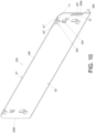
FIG. 10 is a perspective view of the supporting device according to another embodiment of the invention; -
FIG. 11 shows that the supporting device according to said another embodiment of the invention is mounted on a rack, with an object displaced in a predetermined direction in order to be mounted on the supporting device; and -
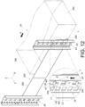
FIG. 12 shows that the supporting device according to said another embodiment of the invention is mounted on the rack, with the object further displaced in the predetermined direction in order to be mounted on the supporting device. - Referring to
FIG. 1 andFIG. 2 , a pair of supportingdevices 22 according to an embodiment of the present invention can be used to mount anobject 20 on a rack. Theobject 20 has afront portion 20a and arear portion 20b. The rack has a left side and a right side that have substantially the same structural configuration. For example, the left side of the rack includes at least one post, such as but not limited to a first post 24 (e.g., a front post) and a second post 26 (e.g., a rear post), wherein thefirst post 24 and thesecond post 26 have substantially the same structural configuration (for example, both thefirst post 24 and thesecond post 26 include a plurality of mountingholes 28 that are arranged at intervals along the height direction of the first and thesecond posts 24 and 26). The pair of supportingdevices 22 have substantially the same structural configuration. Each supportingdevice 22 includes alongitudinal portion 30, at least one first mountingportion 32, and anelastic member 34. Preferably, each supportingdevice 22 further includes a supportingportion 36 bent with respect to the correspondinglongitudinal portion 30, and each supportingportion 36 is substantially perpendicularly connected to the correspondinglongitudinal portion 30 and is configured to support a bottom portion of theobject 20. - It is worth mentioning that in the coordinate system used in
FIG. 1 andFIG. 2 , the X-axis direction is defined as the longitudinal direction, the Y-axis direction as the transverse (or lateral) direction, and the Z-axis direction as the vertical direction (or the height direction of the first and thesecond posts 24 and 26). The X axis, the Y axis, and the Z axis are perpendicular to one another. - Referring to
FIG. 3 ,FIG. 4 , andFIG. 5 , the mountingholes 28 of thefirst post 24 and of thesecond post 26 have substantially the same structural configuration. Each mountinghole 28 is defined by the contours of its hole walls. For example, each mountinghole 28 is defined jointly by a lower hole wall W1, an upper hole wall W2, a front hole wall W3, and a rear hole wall W4 (seeFIG. 3 ). In practice, the structural configuration of each mountinghole 28 is not limited to that disclosed herein. - The at least one first mounting
portion 32 and theelastic member 34 of the supportingdevice 22 are both provided on thelongitudinal portion 30. In this embodiment, there are a plurality of first mountingportions 32 by way of example only. Theelastic member 34 is provided with a second mountingportion 35, such as but not limited to a projection. - Preferably, the
longitudinal portion 30 of the supportingdevice 22 has two opposite sides defined respectively as afirst side S 1 and a second side S2. Each first mountingportion 32 includes a first extension section K1 and a second extension section K2. The first extension sections K1 are connected to thelongitudinal portion 30, and the first extension sections K1 extend transversely (or laterally) beyond the second side S2. Each second extension section K2 is bent with respect to the corresponding first extension section K1, and in this embodiment, each second extension section K2 is substantially perpendicularly connected to the corresponding first extension section K1 by way of example. Each first extension section K1 and the corresponding second extension section K2 jointly constitute a hook to be hung on a hole wall (e.g., the lower hole wall W1) of any of the mountingholes 28 of thefirst post 24 such that the corresponding first mountingportion 32 is mounted at a first predetermined position L1 on the first post 24 (seeFIG. 4 ). - Preferably, the
longitudinal portion 30 of the supportingdevice 22 has afirst end 30a and asecond end 30b (such as but not limited to a front end and a rear end). The first mountingportions 32 are adjacent to thefirst end 30a of thelongitudinal portion 30, and thelongitudinal portion 30 is further provided with at least one auxiliary mountingportion 38 adjacent to thesecond end 30b of thelongitudinal portion 30. In this embodiment, the number of the at least one auxiliary mountingportion 38 is the same as that of the at least one first mountingportion 32. Theauxiliary mounting portions 38 have substantially the same structural configuration as the first mountingportions 32, and the way in which theauxiliary mounting portions 38 are mounted on thesecond post 26 is substantially the same as the way in which the first mountingportions 32 are mounted on thefirst post 24. More specifically, each auxiliary mountingportion 38 is configured to be hung on a hole wall (e.g., the lower hole wall W1) of any of the mountingholes 28 of thesecond post 26 and thus be mounted at a first predetermined position L1 on the second post 26 (seeFIG. 4 ). - The
elastic member 34 includes a connectingportion 40, a guidingportion 42, and anelastic portion 44 provided between the connectingportion 40 and the guidingportion 42. The connectingportion 40 is connected (e.g., fixedly connected) to apredetermined portion 43 of the first side S1 of thelongitudinal portion 30. Theelastic portion 44 is tilted up at a predetermined angle with respect to the first side S1 of the longitudinal portion 30 (seeFIG. 5 ). The guidingportion 42 is bent with respect to theelastic portion 44 toward the first side S1 of the longitudinal portion 30 (seeFIG. 5 ), and the guidingportion 42 includes, for example but not limited to, an inclined surface or a curved surface. - Preferably, the
longitudinal portion 30 includes a throughhole 46 that brings thefirst side S 1 and the second side S2 into communication with each other, the second mountingportion 35 is provided on theelastic portion 44 of theelastic member 34, and the second mountingportion 35 can be passed from thefirst side S 1 to the second side S2 through the throughhole 46. The position of the second mountingportion 35 corresponds to one of the mountingholes 28 of the first post 24 (seeFIG. 4 ). - Preferably, when each first mounting
portion 32 is hung on a hole wall (e.g., the lower hole wall W1) of one of the mountingholes 28 of thefirst post 24, the first extension section K1 of each first mountingportion 32 is supported by the hole wall (e.g., the lower hole wall W1) of the corresponding mountinghole 28, and the second extension section K2 of each first mountingportion 32 is spaced apart from thefirst post 24 by a transverse distance. This transverse distance allows the supportingdevice 22 to be transversely displaced with respect to the rack (seeFIG. 4 ). - Referring to
FIG. 6 andFIG. 7 , the supportingdevice 22 is mounted (or hung) on thefirst post 24 and thesecond post 26 of the rack via the first mountingportions 32 and the auxiliary mountingportions 38 respectively, and theelastic member 34 is in a non-locking state X1 (e.g., an unlocking state as shown inFIG. 6 ). When theelastic member 34 is in the non-locking state X1, theelastic portion 44 of theelastic member 34 is tilted up at the predetermined angle with respect to thefirst side S 1 of the longitudinal portion 30 (seeFIG. 6 ), and the second mountingportion 35 corresponds in position to one of the mountingholes 28 of the first post 24 (as shown inFIG. 7 , in which the second mountingportion 35 has yet to enter that mountinghole 28 of the first post 24). Theobject 20 can now be displaced in a predetermined direction D in order to be mounted on the supportingdevice 22. During the mounting process, therear portion 20b of theobject 20 will come into contact with the guidingportion 42 of the elastic member 34 (seeFIG. 6 ), thus not only making it easier for a portion (e.g., a lateral side L) of theobject 20 to move past theelastic member 34, but also allowing a bottom portion B of theobject 20 to be partially supported by the supporting portion 36 (seeFIG. 6 andFIG. 7 ). It can be seen inFIG. 6 andFIG. 7 that when theelastic member 34 is in the non-locking state X1 (seeFIG. 6 ), the second mountingportion 35 is relatively far away from the first mounting portions 32 (seeFIG. 7 ); for example, the second mountingportion 35 is not aligned with the first mountingportions 32 in the vertical direction (the Z-axis direction). - Referring to
FIG. 8 andFIG. 9 , when the first mountingportions 32 are mounted at their respective first predetermined positions L1 on thefirst post 24 of the rack (e.g., when each first mountingportion 32 is hung on the lower hole wall W1 of one of the mountingholes 28 of thefirst post 24, as shown inFIG. 9 ) and a force F is applied to the elastic member 34 (seeFIG. 8 ), theelastic member 34 is changed from the non-locking state X1 to a locking state X2 such that the second mountingportion 35 is mounted at a second predetermined position L2 on thefirst post 24 of the rack (e.g., with the second mountingportion 35 inserted in one of the mountingholes 28 of thefirst post 24, as shown inFIG. 9 ), thereby preventing the first mountingportions 32 from moving away from their respective first predetermined positions L1 on thefirst post 24 of the rack (e.g., preventing each first mountingportion 32 from moving away from the lower hole wall W1 of the corresponding mountinghole 28 of thefirst post 24 in a height direction H, as shown inFIG. 9 ); as a result, the supportingdevice 22 is locked to the rack. Preferably, when the second mountingportion 35 is mounted at the second predetermined position L2 on thefirst post 24 of the rack, the mounting gap between the second mountingportion 35 and the upper hole wall W2 of the mountinghole 28 in which the second mountingportion 35 is inserted is smaller than the extension length of the second extension section K2 of each first mountingportion 32, in order to prevent the first mountingportions 32 from moving away from their respective first predetermined positions L1 on thefirst post 24 of the rack (seeFIG. 9 ). It is worth mentioning that the second predetermined position L2 corresponds to the same mountinghole 28 as a first predetermined position L1. More specifically, the first predetermined positions L1 are mounting positions whereas the second predetermined position L2 is a locking position. - The
object 20 can be further pushed in the predetermined direction D in order to be mounted on the supportingdevice 22 completely. During the mounting process, the aforesaid portion (e.g., the lateral side L) of theobject 20 applies the force F and thereby depresses theelastic portion 44 of the elastic member 34 (as shown inFIG. 8 , with theelastic portion 44 of theelastic member 34 accumulating an elastic force that tends to act in the opposite direction of the force F) such that theelastic member 34 is changed from the non-locking state X1 to the locking state X2. The second mountingportion 35 ends up mounted at the second predetermined position L2 on thefirst post 24 of the rack (e.g., inserted in the corresponding mountinghole 28 of thefirst post 24, as shown inFIG. 9 ) to prevent the first mountingportions 32 from moving away from their respective first predetermined positions L1 on thefirst post 24 of the rack (e.g., to prevent each first mountingportion 32 from moving away from the lower hole wall W1 of the corresponding mountinghole 28 of thefirst post 24 in the height direction H, as shown inFIG. 9 ), and the supportingdevice 22 is thus securely locked to the rack. When theobject 20 reaches a fully retracted position after being further displaced in the predetermined direction D, the bottom portion B of theobject 20 is supported entirely by the supportingportion 36 of the supporting device 22 (seeFIG. 1 ). It can be seen inFIG. 8 andFIG. 9 that when theelastic member 34 is in the locking state X2 (seeFIG. 8 ), the second mountingportion 35 is relatively close to the first mounting portions 32 (seeFIG. 9 ); for example, the second mountingportion 35 is adjacent to or aligned with the first mountingportions 32 in the vertical direction (the Z-axis direction). - It is worth mentioning that when the first mounting portions 32 are mounted at their respective first predetermined positions L1 on the first post 24 of the rack (e.g., when each first mounting portion 32 is mounted on the lower hole wall W1 of one of the mounting holes 28 of the first post 24) but the force F is not applied to the elastic member 34 (e.g., when the lateral side L of the object 20 has yet to depress the elastic portion 44 of the elastic member 34, or when the object 20 has been detached from the supporting device 22), the elastic portion 44 of the elastic member 34 releases the accumulated elastic force and returns from the locking state X2 to the non-locking state X1 such that the second mounting portion 35 is no longer mounted at the second predetermined position L2 on the first post 24 of the rack (e.g., the second mounting portion 35 is moved away from the corresponding mounting hole 28 of the first post 24 of the rack), thereby allowing the first mounting portions 32 to move away from their respective first predetermined positions L1 on the first post 24 of the rack in the height direction H and hence from the corresponding mounting holes 28 of the first post 24 of the rack respectively, and the auxiliary mounting portions 38 to move away from the corresponding mounting holes 28 of the second post 26 of the rack respectively, too. The supporting
device 22, therefore, can be detached from the rack (or more specifically from thefirst post 24 andsecond post 26 of the rack) with ease. -
FIG. 10 depicts the supportingdevice 200 according to another embodiment of the present invention. The supportingdevice 200 in this embodiment is different from the supportingdevice 22 in the previous embodiment mainly in that the supportingdevice 200 does not include theelastic member 34 in the previous embodiment (i.e., the second mountingportion 204 of the supportingdevice 200 is not provided on the elastic member 34). More specifically, both the first mountingportion 202 and the second mountingportion 204 of the supportingdevice 200 are provided directly on thelongitudinal portion 206. The first mountingportion 202 includes a first extension section K1' and a second extension section K2'. The first extension section K1' is connected to thelongitudinal portion 206, and the first extension section K1' extends transversely (or laterally) beyond the second side S2 of thelongitudinal portion 206. The second extension section K2' is bent with respect to the first extension section K1', and in this embodiment, the second extension section K2' is substantially perpendicularly connected to the first extension section K1' by way of example. Thesecond mounting portion 204 extends transversely (or laterally) beyond the second side S2 of thelongitudinal portion 206 too and is a projection by way of example. The first extension section K1' of the first mountingportion 202 has a first transverse length T1 extending from the second side S2 of thelongitudinal portion 206, and the second mountingportion 204 has a second transverse length T2 extending from the second side S2 of thelongitudinal portion 206. The second transverse length T2 is less than the first transverse length T1. - Referring to
FIG. 11 andFIG. 12 , the first extension section K1' and the second extension section K2' of the first mountingportion 202 jointly constitute a hook to be hung on a hole wall (e.g., the lower hole wall W1) of any of the mountingholes 28 of thefirst post 24 of the rack such that the first mountingportion 202 is mounted at a first predetermined position L1 on thefirst post 24. - When the first mounting
portion 202 is hung on a hole wall (e.g., the lower hole wall W1) of one of the mountingholes 28 of thefirst post 24, the first extension section K1' of the first mountingportion 202 is supported by the hole wall (e.g., the lower hole wall W1), and the second extension section K2' of the first mountingportion 202 is spaced apart from thefirst post 24 by a transverse distance T (seeFIG. 12 ). The transverse distance T allows the supportingdevice 200 to be transversely displaced with respect to the rack. For example, the supportingdevice 200 can be at a first position P1 (seeFIG. 11 ) or a second position P2 (seeFIG. 12 ) with respect to the rack. - When the supporting
device 200 arrives at the second position P2 (seeFIG. 12 ) after being transversely displaced with respect to the rack from the first position P1 (seeFIG. 11 ), the second mountingportion 204 is mounted at a second predetermined position L2 on the first post 24 (e.g., the second mountingportion 204 is inserted in another mountinghole 28, say mounting hole 28', of thefirst post 24, as shown inFIG. 12 ) to prevent the first mountingportion 202 from moving away from the first predetermined position L1 on the rack (e.g., to prevent the first mountingportion 202 from moving away from the lower hole wall W1 of the corresponding mountinghole 28 of thefirst post 24 in the height direction H, as shown inFIG. 12 ); consequently, the supportingdevice 200 is locked to the rack. In this embodiment, the first predetermined position L1 and the second predetermined position L2 correspond to different mountingholes 28 respectively. The first predetermined position L1 is a mounting position whereas the second predetermined position L2 is a locking position. - Preferably, when the second mounting
portion 204 is mounted at the second predetermined position L2 on thefirst post 24 of the rack, the mounting gap between the second mountingportion 204 and the upper hole wall W2 of the mounting hole 28' is smaller than the extension length of the second extension section K2' of the first mountingportion 202, in order to prevent the first mountingportion 202 from moving away from the first predetermined position L1 on thefirst post 24 of the rack (seeFIG. 12 ). - Preferably, when the first mounting
portion 202 is mounted at the first predetermined position L1 on thefirst post 24 of the rack (e.g., when the first mountingportion 202 is hung on the lower hole wall W1 of the corresponding mountinghole 28 of the first post 24) but the second mountingportion 204 is not mounted at the second predetermined position L2 on the rack (e.g., when the second mountingportion 204 has yet to be inserted in the mounting hole 28' of thefirst post 24, as shown inFIG. 11 ), the first mountingportion 202 is allowed to move away from the first predetermined position L1 on thefirst post 24 of the rack. - Preferably, the supporting
portion 208 of the supportingdevice 200 is configured to support theobject 20, and theobject 20 can drive the supportingdevice 200 into transverse displacement from the first position P1 to the second position P2 with respect to the rack. For example, in the course in which theobject 20 is displaced in the predetermined direction D in order to be mounted on the supportingdevice 200, a portion (e.g., the lateral side L) of theobject 20 pushes the supportingdevice 200 and thereby displaces the supportingdevice 200 transversely from the first position P1 (seeFIG. 11 ) to the second position P2 (seeFIG. 12 ) with respect to the rack. - Preferably, one of the
longitudinal portion 206 and theobject 20 is provided with a guidingfeature 207 such as an inclined surface or a curved surface (as shown inFIG. 10 andFIG. 11 ). Here, by way of example, the guidingfeature 207 is adjacent to thefirst end 206a of thelongitudinal portion 206 so that while theobject 20 is being displaced in the predetermined direction D in order to be mounted on the supportingdevice 200, the guidingfeature 207 makes it easier for theobject 20 to push, and thereby transversely displace, the supportingdevice 200 from the first position P1 (seeFIG. 11 ) to the second position P2 (seeFIG. 12 ). - Preferably, the
auxiliary mounting portion 210 is configured to be hung on a hole wall (e.g., the lower hole wall W1) of any of the mountingholes 28 of thepost 26 so as to be mounted at a first predetermined position L1 on the second post 26 (as shown inFIG. 11 andFIG. 12 ). - It can be known from the above that the supporting
device 22/200 of the present invention has the following features: - 1. In the first embodiment of the present invention, the
elastic member 34 can be changed from the non-locking state X1 to the locking state X2 by the force F applied to theelastic member 34 when the first mountingportions 32 are mounted at their respective first predetermined positions L1 on the rack, thus mounting the second mountingportion 35 at the second predetermined position L2 on the rack to prevent the first mountingportions 32 from moving away from their respective first predetermined positions L1 on the rack and to thereby lock the supportingdevice 22 to the rack. When the first mountingportions 32 are mounted at their respective first predetermined positions L1 on the rack but the force F is not applied to theelastic member 34, theelastic member 34 returns elastically from the locking state X2 to the non-locking state X1 such that the second mountingportion 35 is no longer mounted at the second predetermined position L2 on the rack. The first mountingportions 32 are therefore allowed to move away from their respective first predetermined positions L1 on the rack to unlock the supportingdevice 22 from the rack. In terms of actual application, when theelastic member 34 is not depressed by theobject 20 or when theobject 20 has been detached from the supportingdevice 22, theelastic member 34 is not subjected to the force F and hence returns elastically from the locking state X2 to the non-locking state XI, in which the second mountingportion 35 is not mounted at the second predetermined position L2 on the rack, meaning the supportingdevice 22 is not locked to, and can be easily detached from, the rack. - 2. In the second embodiment of the present invention, the supporting
device 200 can be displaced transversely with respect to the rack when the first mountingportion 202 is mounted (hung) on a hole wall (e.g., the lower hole wall W1) of one of the mountingholes 28 of thefirst post 24 and thus located at the first predetermined position L1. When the supportingdevice 200 is at the first position PI, the second mountingportion 204 of the supportingdevice 200 is not mounted at the second predetermined position L2 on thefirst post 24 of the rack, so the first mountingportion 202 can be moved away from the first predetermined position L1 on thefirst post 24 of the rack to unlock the supportingdevice 200 from the rack, allowing a user to easily detach the supportingdevice 200 from the rack. Once the supportingdevice 200 is transversely displaced with respect to the rack from the first position P1 to the second position P2, however, the second mountingportion 204 is mounted at the second predetermined position L2 on thefirst post 24 of the rack to prevent the first mountingportion 202 from moving away from the first predetermined position L1 on thefirst post 24 of the rack and to thereby lock the supportingdevice 200 to the rack. - While the present invention has been disclosed through the preferred embodiments described above, those embodiments are not intended to be restrictive of the scope of the invention. The scope of the patent protection sought by the applicant is defined by the appended claims.
Claims (15)
- A supporting device (22) adapted to be mounted on a rack, the supporting device (22) comprising:a longitudinal portion (30); anda first mounting portion (32) provided on the longitudinal portion (30);characterized inthat the supporting device (22) further comprises an elastic member (34) provided on the longitudinal portion (30), the elastic member (34) being configured to be in one of a locking state (X2) and a non-locking state (XI), the elastic member (34) being provided with a second mounting portion (35);wherein when the first mounting portion (32) is mounted at a first predetermined position (L1) on the rack and a force (F) is applied to the elastic member (34), the elastic member (34) is changed from the non-locking state (X1) to the locking state (X2) such that the second mounting portion (35) is mounted at a second predetermined position (L2) on the rack to prevent the first mounting portion (32) from moving away from the first predetermined position (L1) on the rack.
- The supporting device (22) as claimed in claim 1, wherein the second mounting portion (35) is relatively far away from the first mounting portion (32) when the elastic member (34) is in the non-locking state (XI); wherein the second mounting portion (35) is relatively close to the first mounting portion (32) when the elastic member (34) is in the locking state (X2).
- The supporting device (22) as claimed in claim 1 or 2, wherein when the first mounting portion (32) is mounted at the first predetermined position (L1) on the rack but the force (F) is not applied to the elastic member (34), the elastic member (34) is in the non-locking state (XI), and the second mounting portion (35) is therefore not mounted at the second predetermined position (L2) on the rack such that the first mounting portion (32) is allowed to move away from the first predetermined position (L1) on the rack.
- The supporting device (22) as claimed in any one of claims 1-3, further comprising a supporting portion (36) bent with respect to the longitudinal portion (30), wherein the supporting portion (36) is configured to support an object (20), and the object (20) is able to apply the force (F) and thereby depress the elastic member (34) such that the elastic member (34) is changed from the non-locking state (X1) to the locking state (X2).
- The supporting device (22) as claimed in any one of claims 1-4, wherein the longitudinal portion (30) has two opposite sides defined respectively as a first side (S1) and a second side (S2); and wherein the elastic member (34) includes a connecting portion (40), a guiding portion (42), and an elastic portion (44) provided between the connecting portion (40) and the guiding portion (42), the connecting portion (40) is connected to the first side (S1) of the longitudinal portion (30), and the elastic portion (44) is tilted up with respect to the first side (S 1); and wherein the longitudinal portion (30) includes a through hole (46), the through hole (46) brings the first side (S1) and the second side (S2) into communication with each other, the second mounting portion (35) is provided on the elastic portion (44) of the elastic member (34), and the second mounting portion (35) is configured to be passed from the first side (S1) through the through hole (46) to the second side (S2).
- The supporting device (22) as claimed in any one of claims 1-5, wherein the rack includes a front post (24) and a rear post (26), and each of the front post (24) and the rear post (26) includes a plurality of mounting holes (28); wherein the longitudinal portion (30) has a first end (30a) and a second end (30b), the first mounting portion (32) is adjacent to the first end (30a) of the longitudinal portion (30), and the longitudinal portion (30) is further provided with an auxiliary mounting portion (38) adjacent to the second end (30b) of the longitudinal portion (30); and wherein the first mounting portion (32) is configured to be mounted at the first predetermined position (L1) of any of the mounting holes (28) of the front post (24), and the auxiliary mounting portion (38) is configured to be mounted at the first predetermined position (L1) of any of the mounting holes (28) of the rear post (26).
- The supporting device (22) as claimed in any one of claims 1-6, wherein each of the first mounting portion (32) and the auxiliary mounting portion (38) includes a first extension section (K1) and a second extension section (K2), the first extension sections (K1) are connected to the longitudinal portion (30), each said second extension section (K2) is bent with respect to a corresponding said first extension section (K1), and each said first extension section (K1) and the corresponding second extension section (K2) jointly constitute a hook to be hung on a hole wall (W1) of any of the mounting holes (28) of the front post (24) or of the rear post (26).
- The supporting device (22) as claimed in claim 7, wherein each said second extension section (K2) is substantially perpendicularly connected to the corresponding first extension section (K1); and wherein when the first mounting portion (32) is hung on the hole wall (W1) of one of the mounting holes (28) of the front post (24), the first extension section (K1) of the first mounting portion (32) is supported by the hole wall (W1), and the second extension section (K2) of the first mounting portion (32) is spaced apart from the front post (24) by a transverse distance, the transverse distance allowing the supporting device (22) to be displaced transversely with respect to the rack.
- A supporting device (200) adapted to be mounted on a rack, wherein the rack includes a first post (24), and the first post (24) includes a plurality of mounting holes (28), the supporting device (200) comprising:a longitudinal portion (206); anda first mounting portion (202) and a second mounting portion (204), both provided on the longitudinal portion (206);wherein the first mounting portion (202) includes a first extension section (K1') and a second extension section (K2'), the first extension section (K1') is connected to the longitudinal portion (206), the second extension section (K2') is bent with respect to the first extension section (K1'), and the first extension section (K1') and the second extension section (K2') jointly constitute a hook to be hung on a hole wall (W1) of any of the mounting holes (28) of the first post (24) and thus located at a first predetermined position (LI);wherein when the first mounting portion (202) is hung on the hole wall (W1) of one of the mounting holes (28), the first extension section (K1') of the first mounting portion (202) is supported by the hole wall (W1);characterized inthat the second extension section (K2') of the first mounting portion (202) is spaced apart from the first post (24) by a transverse distance (T), the transverse distance (T) allowing the supporting device (200) to be displaced transversely with respect to the rack;wherein when the supporting device (200) reaches a second position (P2) after being transversely displaced with respect to the rack from a first position (P1), the second mounting portion (204) is mounted at a second predetermined position (L2) on the rack to prevent the first mounting portion (202) from moving away from the first predetermined position (L1) on the rack.
- The supporting device (200) as claimed in claim 9, wherein the first extension section (K1') of the first mounting portion (202) has a first transverse length (T1), and the second mounting portion (204) has a second transverse length (T2) less than the first transverse length (T1).
- The supporting device (200) as claimed in claim 10, wherein when the first mounting portion (202) is mounted at the first predetermined position (L1) on the rack but the second mounting portion (204) is not mounted at the second predetermined position (L2) on the rack, the first mounting portion (202) is allowed to move away from the first predetermined position (L1) on the rack.
- The supporting device (200) as claimed in any one of claims 9-11, further comprising a supporting portion (208) bent with respect to the longitudinal portion (206), wherein the supporting portion (208) is configured to support an object (20), and the object (20) is able to drive the supporting device (200) into transverse displacement from the first position (P1) to the second position (P2) with respect to the rack.
- The supporting device (200) as claimed in any one of claims 9-12, wherein the rack further includes a second post (26), and the second post (26) includes a plurality of mounting holes (28); wherein the longitudinal portion (206) has a first end (206a) and a second end (30b), the first mounting portion (202) is adjacent to the first end (206a) of the longitudinal portion (206), and the longitudinal portion (206) is further provided with an auxiliary mounting portion (210) adjacent to the second end (30b) of the longitudinal portion (206); wherein the first mounting portion (202) is configured to be mounted at the first predetermined position (L1) of any of the mounting holes (28) of the first post (24), and the auxiliary mounting portion (210) is configured to be mounted at the first predetermined position (L1) of any of the mounting holes (28) of the second post (26); wherein the auxiliary mounting portion (210) is substantially identical to the first mounting portion (202) in structural configuration, and the auxiliary mounting portion (210) is configured to be hung on a hole wall (W1) of any of the mounting holes (28) of the second post (26).
- The supporting device (200) as claimed in claim 13, wherein the second extension section (K2') is substantially perpendicularly connected to the first extension section (K1').
- The supporting device (22) as claimed in claim 4 or 12, wherein the supporting portion (36) is substantially perpendicularly connected to the longitudinal portion (30).
Applications Claiming Priority (1)
| Application Number | Priority Date | Filing Date | Title |
|---|---|---|---|
| TW110127629A TWI753843B (en) | 2021-07-26 | 2021-07-26 | Supporting device |
Publications (2)
| Publication Number | Publication Date |
|---|---|
| EP4125311A1 true EP4125311A1 (en) | 2023-02-01 |
| EP4125311B1 EP4125311B1 (en) | 2026-01-07 |
Family
ID=78413816
Family Applications (1)
| Application Number | Title | Priority Date | Filing Date |
|---|---|---|---|
| EP21205021.5A Active EP4125311B1 (en) | 2021-07-26 | 2021-10-27 | Supporting device |
Country Status (4)
| Country | Link |
|---|---|
| US (1) | US12055169B2 (en) |
| EP (1) | EP4125311B1 (en) |
| JP (1) | JP7260622B2 (en) |
| TW (1) | TWI753843B (en) |
Families Citing this family (3)
| Publication number | Priority date | Publication date | Assignee | Title |
|---|---|---|---|---|
| TWI852504B (en) * | 2023-04-25 | 2024-08-11 | 緯創資通股份有限公司 | Lifting module and electronic device |
| US12588758B2 (en) * | 2023-11-14 | 2026-03-31 | Textron Innovations Inc. | Rack shelf systems and method for loading payloads into a rack shelf system |
| US12289857B1 (en) * | 2024-03-19 | 2025-04-29 | Martas Precision Slide Co., Ltd. | Bracket for open rack |
Citations (7)
| Publication number | Priority date | Publication date | Assignee | Title |
|---|---|---|---|---|
| US5470143A (en) * | 1994-03-24 | 1995-11-28 | Steelcase Inc. | Self-locking snap-on suspension unit for furniture cabinets and the like |
| US7975860B2 (en) * | 2008-04-21 | 2011-07-12 | International Business Machines Corporation | Toolless rail mounting for a computer system rack |
| US20110233355A1 (en) * | 2010-03-24 | 2011-09-29 | Hong Fu Jin Precision Industry (Shenzhen) Co., Ltd. | Mounting appratus for slide rail |
| US8727138B2 (en) | 2011-11-04 | 2014-05-20 | International Business Machines Corporation | Toolless rail enabling simplified installation and removal |
| US20140175033A1 (en) * | 2012-12-26 | 2014-06-26 | Hon Hai Precision Industry Co., Ltd. | Electronic device rack |
| US8770528B2 (en) | 2008-09-25 | 2014-07-08 | King Slide Works Co., Ltd. | Bracket assembly for a rack |
| US20150173510A1 (en) * | 2013-12-19 | 2015-06-25 | Hong Fu Jin Precision Industry (Shenzhen) Co., Ltd. | Slide rail device |
Family Cites Families (7)
| Publication number | Priority date | Publication date | Assignee | Title |
|---|---|---|---|---|
| US6398041B1 (en) * | 1999-12-03 | 2002-06-04 | Hewlett-Packard Company | Snap system for retaining slide mounted rack system into multiple racks without tools |
| US6769551B2 (en) * | 2002-07-26 | 2004-08-03 | Dell Products L.P. | System and method for utilizing non-dedicated rack space |
| CN103379790A (en) * | 2012-04-25 | 2013-10-30 | 鸿富锦精密工业(深圳)有限公司 | Machine cabinet |
| TWI568381B (en) | 2015-12-21 | 2017-02-01 | 川湖科技股份有限公司 | Slide rail assembly and guiding mechanism thereof |
| TWI664889B (en) | 2016-09-24 | 2019-07-01 | 川湖科技股份有限公司 | Bracket device |
| TWI664892B (en) * | 2018-05-30 | 2019-07-01 | 川湖科技股份有限公司 | Bracket device for rack system and slide rail assembly |
| TWI721931B (en) * | 2020-09-24 | 2021-03-11 | 川湖科技股份有限公司 | Slide rail kit |
-
2021
- 2021-07-26 TW TW110127629A patent/TWI753843B/en active
- 2021-10-20 US US17/505,807 patent/US12055169B2/en active Active
- 2021-10-27 EP EP21205021.5A patent/EP4125311B1/en active Active
- 2021-12-01 JP JP2021195097A patent/JP7260622B2/en active Active
Patent Citations (7)
| Publication number | Priority date | Publication date | Assignee | Title |
|---|---|---|---|---|
| US5470143A (en) * | 1994-03-24 | 1995-11-28 | Steelcase Inc. | Self-locking snap-on suspension unit for furniture cabinets and the like |
| US7975860B2 (en) * | 2008-04-21 | 2011-07-12 | International Business Machines Corporation | Toolless rail mounting for a computer system rack |
| US8770528B2 (en) | 2008-09-25 | 2014-07-08 | King Slide Works Co., Ltd. | Bracket assembly for a rack |
| US20110233355A1 (en) * | 2010-03-24 | 2011-09-29 | Hong Fu Jin Precision Industry (Shenzhen) Co., Ltd. | Mounting appratus for slide rail |
| US8727138B2 (en) | 2011-11-04 | 2014-05-20 | International Business Machines Corporation | Toolless rail enabling simplified installation and removal |
| US20140175033A1 (en) * | 2012-12-26 | 2014-06-26 | Hon Hai Precision Industry Co., Ltd. | Electronic device rack |
| US20150173510A1 (en) * | 2013-12-19 | 2015-06-25 | Hong Fu Jin Precision Industry (Shenzhen) Co., Ltd. | Slide rail device |
Also Published As
| Publication number | Publication date |
|---|---|
| TWI753843B (en) | 2022-01-21 |
| JP2023017677A (en) | 2023-02-07 |
| US20230029230A1 (en) | 2023-01-26 |
| US12055169B2 (en) | 2024-08-06 |
| EP4125311B1 (en) | 2026-01-07 |
| JP7260622B2 (en) | 2023-04-18 |
| TW202304347A (en) | 2023-02-01 |
Similar Documents
| Publication | Publication Date | Title |
|---|---|---|
| US20230029230A1 (en) | Supporting device | |
| US7404736B2 (en) | Patch panel and strain relief bar assembly | |
| US10292493B2 (en) | Bracket device | |
| JP7194771B2 (en) | slide rail kit | |
| EP3231325B1 (en) | Bracket device | |
| EP3352547B1 (en) | Slide rail assembly | |
| EP3637968A1 (en) | Cable management assembly | |
| CN115701754B (en) | Supporting device | |
| US20250160515A1 (en) | Fitting assembly and fitting device thereof | |
| JP2006014791A (en) | Shelf plate attaching structure in self-assembly shelf | |
| TWI584764B (en) | Bracket device | |
| JP2018062246A (en) | Lock member mounting structure and mounting method | |
| JP6758149B2 (en) | Lock member mounting structure | |
| EP4427634B1 (en) | Furniture assembly | |
| JP7790013B2 (en) | Support Assembly | |
| TWI600395B (en) | Bracket device | |
| TWI908158B (en) | Supporting assembly and method for mounting the same to rack | |
| CN114554772B (en) | Slide rail assembly | |
| EP3716743B1 (en) | Removable cable arm bracket | |
| JP4231198B2 (en) | Shelf board support device | |
| CN119907213A (en) | Slide rail kit | |
| JP7208745B2 (en) | Mounting structure and mounting method of lock member | |
| CN110557916B (en) | Bracket device for rack system and slide rail assembly | |
| CN113876129A (en) | bracket device | |
| TW202517183A (en) | Slide rail kit |
Legal Events
| Date | Code | Title | Description |
|---|---|---|---|
| PUAI | Public reference made under article 153(3) epc to a published international application that has entered the european phase |
Free format text: ORIGINAL CODE: 0009012 |
|
| STAA | Information on the status of an ep patent application or granted ep patent |
Free format text: STATUS: THE APPLICATION HAS BEEN PUBLISHED |
|
| STAA | Information on the status of an ep patent application or granted ep patent |
Free format text: STATUS: REQUEST FOR EXAMINATION WAS MADE |
|
| AK | Designated contracting states |
Kind code of ref document: A1 Designated state(s): AL AT BE BG CH CY CZ DE DK EE ES FI FR GB GR HR HU IE IS IT LI LT LU LV MC MK MT NL NO PL PT RO RS SE SI SK SM TR |
|
| 17P | Request for examination filed |
Effective date: 20230125 |
|
| RBV | Designated contracting states (corrected) |
Designated state(s): AL AT BE BG CH CY CZ DE DK EE ES FI FR GB GR HR HU IE IS IT LI LT LU LV MC MK MT NL NO PL PT RO RS SE SI SK SM TR |
|
| GRAP | Despatch of communication of intention to grant a patent |
Free format text: ORIGINAL CODE: EPIDOSNIGR1 |
|
| STAA | Information on the status of an ep patent application or granted ep patent |
Free format text: STATUS: GRANT OF PATENT IS INTENDED |
|
| INTG | Intention to grant announced |
Effective date: 20250904 |
|
| GRAS | Grant fee paid |
Free format text: ORIGINAL CODE: EPIDOSNIGR3 |
|
| GRAA | (expected) grant |
Free format text: ORIGINAL CODE: 0009210 |
|
| STAA | Information on the status of an ep patent application or granted ep patent |
Free format text: STATUS: THE PATENT HAS BEEN GRANTED |
|
| AK | Designated contracting states |
Kind code of ref document: B1 Designated state(s): AL AT BE BG CH CY CZ DE DK EE ES FI FR GB GR HR HU IE IS IT LI LT LU LV MC MK MT NL NO PL PT RO RS SE SI SK SM TR |
|
| REG | Reference to a national code |
Ref country code: CH Ref legal event code: F10 Free format text: ST27 STATUS EVENT CODE: U-0-0-F10-F00 (AS PROVIDED BY THE NATIONAL OFFICE) Effective date: 20260107 Ref country code: GB Ref legal event code: FG4D |
|
| REG | Reference to a national code |
Ref country code: DE Ref legal event code: R096 Ref document number: 602021045908 Country of ref document: DE |
|
| REG | Reference to a national code |
Ref country code: IE Ref legal event code: FG4D |