EP4125153A1 - Bus bar assembly with plated electrical contact surface - Google Patents
Bus bar assembly with plated electrical contact surface Download PDFInfo
- Publication number
- EP4125153A1 EP4125153A1 EP22186083.6A EP22186083A EP4125153A1 EP 4125153 A1 EP4125153 A1 EP 4125153A1 EP 22186083 A EP22186083 A EP 22186083A EP 4125153 A1 EP4125153 A1 EP 4125153A1
- Authority
- EP
- European Patent Office
- Prior art keywords
- bus bar
- bore
- insert
- contact
- bar assembly
- Prior art date
- Legal status (The legal status is an assumption and is not a legal conclusion. Google has not performed a legal analysis and makes no representation as to the accuracy of the status listed.)
- Granted
Links
Images




Classifications
-
- H—ELECTRICITY
- H01—ELECTRIC ELEMENTS
- H01R—ELECTRICALLY-CONDUCTIVE CONNECTIONS; STRUCTURAL ASSOCIATIONS OF A PLURALITY OF MUTUALLY-INSULATED ELECTRICAL CONNECTING ELEMENTS; COUPLING DEVICES; CURRENT COLLECTORS
- H01R4/00—Electrically-conductive connections between two or more conductive members in direct contact, i.e. touching one another; Means for effecting or maintaining such contact; Electrically-conductive connections having two or more spaced connecting locations for conductors and using contact members penetrating insulation
- H01R4/10—Electrically-conductive connections between two or more conductive members in direct contact, i.e. touching one another; Means for effecting or maintaining such contact; Electrically-conductive connections having two or more spaced connecting locations for conductors and using contact members penetrating insulation effected solely by twisting, wrapping, bending, crimping, or other permanent deformation
-
- H—ELECTRICITY
- H02—GENERATION; CONVERSION OR DISTRIBUTION OF ELECTRIC POWER
- H02G—INSTALLATION OF ELECTRIC CABLES OR LINES, OR OF COMBINED OPTICAL AND ELECTRIC CABLES OR LINES
- H02G5/00—Installations of bus-bars
- H02G5/005—Laminated bus-bars
-
- H—ELECTRICITY
- H01—ELECTRIC ELEMENTS
- H01R—ELECTRICALLY-CONDUCTIVE CONNECTIONS; STRUCTURAL ASSOCIATIONS OF A PLURALITY OF MUTUALLY-INSULATED ELECTRICAL CONNECTING ELEMENTS; COUPLING DEVICES; CURRENT COLLECTORS
- H01R4/00—Electrically-conductive connections between two or more conductive members in direct contact, i.e. touching one another; Means for effecting or maintaining such contact; Electrically-conductive connections having two or more spaced connecting locations for conductors and using contact members penetrating insulation
- H01R4/58—Electrically-conductive connections between two or more conductive members in direct contact, i.e. touching one another; Means for effecting or maintaining such contact; Electrically-conductive connections having two or more spaced connecting locations for conductors and using contact members penetrating insulation characterised by the form or material of the contacting members
- H01R4/62—Connections between conductors of different materials; Connections between or with aluminium or steel-core aluminium conductors
-
- H—ELECTRICITY
- H02—GENERATION; CONVERSION OR DISTRIBUTION OF ELECTRIC POWER
- H02G—INSTALLATION OF ELECTRIC CABLES OR LINES, OR OF COMBINED OPTICAL AND ELECTRIC CABLES OR LINES
- H02G5/00—Installations of bus-bars
- H02G5/007—Butt joining of bus-bars by means of a common bolt, e.g. splice joint
-
- F—MECHANICAL ENGINEERING; LIGHTING; HEATING; WEAPONS; BLASTING
- F16—ENGINEERING ELEMENTS AND UNITS; GENERAL MEASURES FOR PRODUCING AND MAINTAINING EFFECTIVE FUNCTIONING OF MACHINES OR INSTALLATIONS; THERMAL INSULATION IN GENERAL
- F16B—DEVICES FOR FASTENING OR SECURING CONSTRUCTIONAL ELEMENTS OR MACHINE PARTS TOGETHER, e.g. NAILS, BOLTS, CIRCLIPS, CLAMPS, CLIPS OR WEDGES; JOINTS OR JOINTING
- F16B17/00—Connecting constructional elements or machine parts by a part of or on one member entering a hole in the other and involving plastic deformation
- F16B17/006—Connecting constructional elements or machine parts by a part of or on one member entering a hole in the other and involving plastic deformation of rods or tubes to sheets or plates
-
- F—MECHANICAL ENGINEERING; LIGHTING; HEATING; WEAPONS; BLASTING
- F16—ENGINEERING ELEMENTS AND UNITS; GENERAL MEASURES FOR PRODUCING AND MAINTAINING EFFECTIVE FUNCTIONING OF MACHINES OR INSTALLATIONS; THERMAL INSULATION IN GENERAL
- F16B—DEVICES FOR FASTENING OR SECURING CONSTRUCTIONAL ELEMENTS OR MACHINE PARTS TOGETHER, e.g. NAILS, BOLTS, CIRCLIPS, CLAMPS, CLIPS OR WEDGES; JOINTS OR JOINTING
- F16B19/00—Bolts without screw-thread; Pins, including deformable elements; Rivets
- F16B19/02—Bolts or sleeves for positioning of machine parts, e.g. notched taper pins, fitting pins, sleeves, eccentric positioning rings
-
- F—MECHANICAL ENGINEERING; LIGHTING; HEATING; WEAPONS; BLASTING
- F16—ENGINEERING ELEMENTS AND UNITS; GENERAL MEASURES FOR PRODUCING AND MAINTAINING EFFECTIVE FUNCTIONING OF MACHINES OR INSTALLATIONS; THERMAL INSULATION IN GENERAL
- F16B—DEVICES FOR FASTENING OR SECURING CONSTRUCTIONAL ELEMENTS OR MACHINE PARTS TOGETHER, e.g. NAILS, BOLTS, CIRCLIPS, CLAMPS, CLIPS OR WEDGES; JOINTS OR JOINTING
- F16B2200/00—Constructional details of connections not covered for in other groups of this subclass
- F16B2200/93—Fastener comprising feature for establishing a good electrical connection, e.g. electrostatic discharge or insulation feature
-
- F—MECHANICAL ENGINEERING; LIGHTING; HEATING; WEAPONS; BLASTING
- F16—ENGINEERING ELEMENTS AND UNITS; GENERAL MEASURES FOR PRODUCING AND MAINTAINING EFFECTIVE FUNCTIONING OF MACHINES OR INSTALLATIONS; THERMAL INSULATION IN GENERAL
- F16B—DEVICES FOR FASTENING OR SECURING CONSTRUCTIONAL ELEMENTS OR MACHINE PARTS TOGETHER, e.g. NAILS, BOLTS, CIRCLIPS, CLAMPS, CLIPS OR WEDGES; JOINTS OR JOINTING
- F16B39/00—Locking of screws, bolts or nuts
- F16B39/22—Locking of screws, bolts or nuts in which the locking takes place during screwing down or tightening
- F16B39/28—Locking of screws, bolts or nuts in which the locking takes place during screwing down or tightening by special members on, or shape of, the nut or bolt
- F16B39/282—Locking by means of special shape of work-engaging surfaces, e.g. notched or toothed nuts
-
- F—MECHANICAL ENGINEERING; LIGHTING; HEATING; WEAPONS; BLASTING
- F16—ENGINEERING ELEMENTS AND UNITS; GENERAL MEASURES FOR PRODUCING AND MAINTAINING EFFECTIVE FUNCTIONING OF MACHINES OR INSTALLATIONS; THERMAL INSULATION IN GENERAL
- F16B—DEVICES FOR FASTENING OR SECURING CONSTRUCTIONAL ELEMENTS OR MACHINE PARTS TOGETHER, e.g. NAILS, BOLTS, CIRCLIPS, CLAMPS, CLIPS OR WEDGES; JOINTS OR JOINTING
- F16B5/00—Joining sheets or plates, e.g. panels, to one another or to strips or bars parallel to them
- F16B5/02—Joining sheets or plates, e.g. panels, to one another or to strips or bars parallel to them by means of fastening members using screw-thread
- F16B5/025—Joining sheets or plates, e.g. panels, to one another or to strips or bars parallel to them by means of fastening members using screw-thread specially designed to compensate for misalignement or to eliminate unwanted play
-
- H—ELECTRICITY
- H01—ELECTRIC ELEMENTS
- H01R—ELECTRICALLY-CONDUCTIVE CONNECTIONS; STRUCTURAL ASSOCIATIONS OF A PLURALITY OF MUTUALLY-INSULATED ELECTRICAL CONNECTING ELEMENTS; COUPLING DEVICES; CURRENT COLLECTORS
- H01R4/00—Electrically-conductive connections between two or more conductive members in direct contact, i.e. touching one another; Means for effecting or maintaining such contact; Electrically-conductive connections having two or more spaced connecting locations for conductors and using contact members penetrating insulation
- H01R4/28—Clamped connections, spring connections
- H01R4/30—Clamped connections, spring connections utilising a screw or nut clamping member
- H01R4/304—Clamped connections, spring connections utilising a screw or nut clamping member having means for improving contact
-
- H—ELECTRICITY
- H01—ELECTRIC ELEMENTS
- H01R—ELECTRICALLY-CONDUCTIVE CONNECTIONS; STRUCTURAL ASSOCIATIONS OF A PLURALITY OF MUTUALLY-INSULATED ELECTRICAL CONNECTING ELEMENTS; COUPLING DEVICES; CURRENT COLLECTORS
- H01R4/00—Electrically-conductive connections between two or more conductive members in direct contact, i.e. touching one another; Means for effecting or maintaining such contact; Electrically-conductive connections having two or more spaced connecting locations for conductors and using contact members penetrating insulation
- H01R4/28—Clamped connections, spring connections
- H01R4/30—Clamped connections, spring connections utilising a screw or nut clamping member
- H01R4/34—Conductive members located under head of screw
Definitions
- This provisional patent application is directed to a bus bar assembly with a plated electrical contact surface.
- the resistance of an electrical connection to an electrical bus bar is reduced and stabilized by plating an electrically conductive material, such as tin or silver, on the contact portion of the bus bar.
- the plating material may be applied directly to the contact area of the bus bar.
- directly plating the bus bar has several drawbacks in processing cost. Selectively plating the contact portion requires specialized tooling and additional processing which increases production costs. Plating the entire bus bar is a simpler process but requires more of the costlier tin or silver-plating materials. Therefore, a bus bar with a lower cost plated electrical contact surface remains desired.
- a bus bar assembly includes a bus bar formed of a first electrically conductive material having a planar contact portion.
- the bus bar defines a first bore extending through the contact portion.
- the bus bar assembly further includes a contact insert that is formed of a second electrically conductive material that has a greater hardness than the first electrically conductive material.
- the contact insert defines a first surface that is mechanically and electrically connected to the contact portion of the bus bar.
- the contact insert also defines a second surface plated with a third electrically conductive material different than the second electrically conductive material.
- the contact insert additionally defines a smooth second bore coaxial with the first bore and extending from the first surface to the second surface.
- an annular ring on the second surface around the second bore is plated.
- the third electrically conductive material is silver or tin.
- the first bore has a generally cylindrical shape.
- the contact insert has a generally cylindrical shape.
- the contact insert defines a cylindrical collar extending from the second surface and defining an annular groove therein.
- the collar is in an interference fit with an inner wall of the first bore such that a portion of the bus bar is deformed and disposed within the annular groove.
- the collar includes a lip extending over the groove.
- a diameter of the lip is less than a diameter of the collar.
- the second surface defines a plurality of alternating projections and indentations radially extending from the collar.
- the bus bar defines a cylindrical indentation in the contact portion surrounding the first bore.
- the bus bar defines a cylindrical indentation in the contact portion surrounding the first bore.
- An outer surface of the contact located intermediate the first and second surfaces defines a plurality of serrations extending from the outer surface. This plurality of serrations in an interference fit with the indentation such that a portion of the bus bar is deformed and disposed between the plurality of serrations.
- the plurality of serrations is non-parallel to an axis of the second bore and are non-perpendicular to the axis of the second bore.
- the second surface defines a plurality of alternating projections and indentations radially extending from the second bore.
- the first surface of the contact insert is welded to the contact portion of the bus bar.
- the contact insert defines a cylindrical collar extending from the second surface and defining a plurality of serrations therein.
- the collar is in an interference fit with an inner wall of the first bore such that a portion of the bus bar is deformed and disposed within the plurality of serrations.
- plurality of serrations extends along the collar is a direction parallel to an axis of the second bore.
- the collar and the second bore have an obround cylindrical shape.
- a method of manufacturing a bus bar assembly includes the steps of:
- the method further includes the steps of
- the welding process is selected from a list consisting of sonic welding, laser welding, resistance welding, spin welding, brazing, and soldering processes.
- the welding process is a torsional sonic welding process.
- the contact insert defines a cylindrical collar extending from the second surface and defining an annular groove therein.
- the method further includes the step of forming an interference fit between a collar extending from the contact insert and an inner wall of the first bore such that a portion of the bus bar is deformed and disposed within an annular groove.
- the bus bar defines a cylindrical indentation in the contact portion surrounding the first bore.
- An outer surface of the contact located intermediate the first and second surfaces defines a plurality of serrations extending from the outer surface.
- the method further additionally includes the step of forming an interference fit between a plurality of serrations on an outer edge of the contact insert and the first bore such that a portion of the bus bar is deformed and disposed between the plurality of serrations.
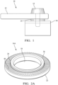
- Fig 1 illustrates a non-limiting example of a bus bar assembly 10.
- the bus bar assembly includes a bus bar 12.
- a bus bar 12 is a bar or strip formed of a solid electrically conductive metal, e.g., a copper or aluminum-based alloy that is configured to carry high electrical currents, e.g., more than 100 amperes. Bus bars are typically used in high power electrical applications such as power stations, industrial power distributions, and electrical vehicles.
- the bus bar assembly 10 also includes an electrical contact insert, hereinafter referred to as the insert 14, that is configured to provide a mechanical and electrical connection feature between the bus bar 12 and an electrical device 16, such as a battery or electric motor.
- the insert 14 is a formed piece of conductive copper material that has a greater hardness than the bus bar.
- FIG.2A-5B A first example of an insert 14A is shown in Figs.2A-5B .
- the insert 14A has a cylindrical shape with a smooth through hole or bore 18 through the center of the insert 14A that is configured to receive a fastener 20, such as a bolt or threaded stud, to attach the bus bar assembly 10 to the electrical device 16.
- the insert 14A may be used in bolted connections where a plated contact surface between the bus bar 12 and the electrical device 16 is desired.
- the insert 14A is plated with an electrically conductive metallic material such as tin or silver, preferably only on a device contact surface 22 which is the bottom surface as shown in Fig. 2A , Fig. 2C , Fig. 3A , and Figs.4-5B .
- the smooth bore 18 allows the fastener 20 to easily pass through and avoids potential cross-threading issues that may occur with a threaded through hole.
- This insert 14A also includes a collar 24 that protrudes from a bus bar contact surface 26 which is arranged generally opposite the device contact surface 22 is shown as the top surface of the insert 14A in Fig. 2A , Fig. 2C , Fig. 3A , and Figs.4-5B .
- the collar 24 has an annular groove 28 that defines stepped surfaces or levels around the perimeter of the collar 24.
- the bus bar 12 also has a cylindrical through hole or bore 30 extending through a contact portion 32 of the bus bar 12.
- the bus bar 12 also defines a cylindrical indentation 34 that surrounds the bus bar bore 30 and is coaxial with the bus bar bore 30.
- the collar 24 and the indentation 34 are sized such that they are in an interference or press fit condition when the collar 24 is inserted within the indentation 34.
- the annular groove 28 includes a lip 36 extending over the groove 28, thereby forming a top edge 38, an inner edge 40, and a bottom edge 42 within the groove 28. As can be seen in Fig. 5A , diameter of the lip 36 is less than a diameter of the collar 24.
- the top edge 38 is non-perpendicular to the inner edge 40 and non-parallel to the bottom edge 42.
- the side walls 44 of the indentation 34 in the bus bar 12 are deformed with at least some the material displaced from the side walls 44 entering and preferably filling the groove 28 in the collar 24, thereby securing the insert 14A within the indentation 34.
- the device contact surface 22 also defines a plurality of alternating projections and indentations 46 that radially extend from the collar 24. This plurality of alternating projections and indentations 46 displaces some of the material on the bottom surface 48 of the indentation 34, thereby inhibiting the insert 14A from twisting within the indentation 34 when a torquing force is applied to the bus bar assembly 10, e.g., by the treaded fastener 20 within the bore 18 of the insert 14A.
- FIG.6A-7 A second example of an insert 14B is shown in Figs.6A-7 .
- This insert also has a cylindrical shape with a smooth through hole or bore 18 through the center of the insert 14B that is configured to receive a fastener 20, such as a bolt or threaded stud, to attach the bus bar assembly 10 to the electrical device 16.
- the insert 14B may be used in bolted connections where a plated contact surface between the bus bar 12 and the electrical device 16 is desired.
- the insert 14B is plated with an electrically conductive metallic material such as tin or silver, preferably only on a device contact surface 22 which is the bottom surface as shown in Fig. 6A, Fig. 6C , and Fig.7 .
- the smooth bore 18 allows the fastener 20 to easily pass through and avoids potential cross-threading issues that may occur with a threaded through hole.
- the insert 14B defines a plurality of serrations 50 that protrudes from an outer edge 52 of the insert 14B.
- the plurality of serrations 50 is arranged at an angle on the outer edge 52 of the insert 14B such that it is both non-parallel and non-perpendicular to an axis X of the bore 18 in the insert 14B.
- the bus bar 12 also has a cylindrical through hole or bore 30 extending through a contact portion 32 of the bus bar 12.
- the bus bar 12 also defines a cylindrical indentation 34 that surrounds the bus bar bore 30 and is coaxial with the bus bar bore 30.
- the plurality of serrations 50 and the indentation 34 are sized such that they are in an interference or press fit condition when the insert 14B is placed within the indentation 34. As shown in Figs.
- the side walls 44 of the indentation 34 in the bus bar 12 are deformed by the plurality of serrations 50 with at least some the material displaced from the side walls 44 entering and preferably filling spaces between the serrations 50, thereby securing the insert 14B within the indentation 34.
- the angled plurality of serrations 50 causes the insert 14B to rotate slightly as the insert 14B is pressed into the indentation 34.
- the plurality of serrations 50 has sharp edges that provide broaching features that break through surface oxides on the bus bar 12 to improve electrical performance and mechanical retention.
- the device contact surface 22 also defines a plurality of alternating projections and indentations 46 in a bus bar contact surface 26 which is arranged generally opposite the device contact surface 22 which is shown as the top surface of the insert in Fig. 6A, Fig. 6C , and Fig.7 .
- the plurality of alternating projections and indentations 46 radially extend from the bore 18. This plurality of alternating projections and indentations 46 displace some of the material on the bottom surface 48 of the indentation 34, thereby inhibiting the insert 14B from twisting within the indentation 34 when a torquing force is applied to the bus bar assembly 10, e.g., by the treaded fastener 20 within the bore 18 of the insert 14B.
- bus bar 12 shows a bore 18 extending through the bus bar 12 surrounded by an indentation 34
- alternative embodiments of a bus bar may only have a bore extending with a uniform diameter through the count portion and the collar or serrations may deform the inner wall of the bore to secure the insert to the bus bar.
- FIG. 8A-8C A third example of an insert 14C is shown in Figs. 8A-8C .
- the insert 14C also has a cylindrical shape with a smooth through hole or bore 18 through the center of the insert 14C that is configured to receive a fastener 20, such as a bolt or threaded stud, to attach the bus bar assembly 10 to the electrical device 16.
- the insert 14C may be used in bolted connections where a plated contact surface between the bus bar 12 and the electrical device 16 is desired.
- the insert 14C is plated with an electrically conductive metallic material such as tin or silver, preferably only on an inner portion 56 of a device contact surface 22 which is the top surface as shown in Figs. 8A-8C .
- the smooth bore 18 allows the fastener 20 to easily pass through and avoids potential cross-threading issues that may occur with a threaded through hole.
- a bus bar contact surface 26 of the insert 14C is generally flat and is welded to a contact portion 32 of the bus bar 12 thereby mechanically and electrically connecting the insert 14C to the contact portion 32 of the bus bar 12.
- the welding is preferably performed using a tortional sonic welding process, However, other sonic welding, laser welding, resistance welding, spin welding, brazing, or soldering processes may also be used in some applications of the bus bar.
- the welding the insert 14C to the contact portion 32 also inhibits the insert 14C from twisting when a torquing force is applied to the bus bar assembly 10, e.g., by a treaded fastener 20 within the bore 18 of the insert 14C.
- FIG. 9A-9C A fourth example of an insert 14D is shown in Figs. 9A-9C .
- the insert 14D has a round or obround cylindrical shape with a smooth through hole or bore 18 through the center of the insert 14D that is configured to receive a fastener 20, such as a bolt or threaded stud, to attach the bus bar assembly 10 to the electrical device 16.
- the bore may also have a round or obround shape.
- An outer surface of the collar 18 defines a plurality of serrations 60 that extend in a direction generally parallel to the bore 18.
- the plurality of serrations 60 are sized such that they are in an interference or press fit condition when the insert 14D is placed within the bus bar bore 30. As shown in Figs.
- the insert 14D is pressed into the bus bar bore 30, the side walls of the bus bar bore 30 are deformed by the plurality of serrations 60 with at least some the material displaced from the side walls entering and preferably filling spaces between the serrations 60, thereby securing the insert 14D within the bus bar bore 30.
- the plurality of serrations 60 has sharp edges that provide broaching features that break through surface oxides in the bus bar bore 30 to improve electrical performance and mechanical retention.
- the insert 14D may be used in bolted connections, as shown in Figs. 11A and 11B , where a plated contact surface between the bus bar 12 and the electrical device 16 is desired.
- the smooth bore 18 allows the fastener 20 to easily pass through and avoids potential cross-threading issues that may occur with a threaded through hole.
- the insert 14D may be mechanically pressed into the bus bar bore 30 to provide a friction fit or may be torsionally welded to the bus bar 12.
- Fig. 12 shows a method 200 of manufacturing a bus bar assembly, such as the bus bar assembly 10 described above.
- the method 200 includes the following steps:
- 'one or more' includes a function being performed by one element, a function being performed by more than one element, e.g., in a distributed fashion, several functions being performed by one element, several functions being performed by several elements, or any combination of the above.
- first, second, etc. are, in some instances, used herein to describe various elements, these elements should not be limited by these terms. These terms are only used to distinguish one element from another.
- a first contact could be termed a second contact, and, similarly, a second contact could be termed a first contact, without departing from the scope of the various described embodiments.
- the first contact and the second contact are both contacts, but they are not the same contact.
- the term “if' is, optionally, construed to mean “when” or “upon” or “in response to determining” or “in response to detecting,” depending on the context.
- the phrase “if it is determined” or “if [a stated condition or event] is detected” is, optionally, construed to mean “upon determining” or “in response to determining” or “upon detecting [the stated condition or event]” or “in response to detecting [the stated condition or event],” depending on the context.
Landscapes
- Connections Effected By Soldering, Adhesion, Or Permanent Deformation (AREA)
Abstract
Description
- This provisional patent application is directed to a bus bar assembly with a plated electrical contact surface.
- The resistance of an electrical connection to an electrical bus bar is reduced and stabilized by plating an electrically conductive material, such as tin or silver, on the contact portion of the bus bar. The plating material may be applied directly to the contact area of the bus bar. However, directly plating the bus bar has several drawbacks in processing cost. Selectively plating the contact portion requires specialized tooling and additional processing which increases production costs. Plating the entire bus bar is a simpler process but requires more of the costlier tin or silver-plating materials. Therefore, a bus bar with a lower cost plated electrical contact surface remains desired.
- According to one or more aspects of the present disclosure, a bus bar assembly includes a bus bar formed of a first electrically conductive material having a planar contact portion. The bus bar defines a first bore extending through the contact portion. The bus bar assembly further includes a contact insert that is formed of a second electrically conductive material that has a greater hardness than the first electrically conductive material. The contact insert defines a first surface that is mechanically and electrically connected to the contact portion of the bus bar. The contact insert also defines a second surface plated with a third electrically conductive material different than the second electrically conductive material. The contact insert additionally defines a smooth second bore coaxial with the first bore and extending from the first surface to the second surface.
- In one or more embodiments of the bus bar assembly according to the previous paragraph, an annular ring on the second surface around the second bore is plated.
- In one or more embodiments of the bus bar assembly according to any one of the previous paragraphs, the third electrically conductive material is silver or tin.
- In one or more embodiments of the bus bar assembly according to any one of the previous paragraphs, the first bore has a generally cylindrical shape.
- In one or more embodiments of the bus bar assembly according to any one of the previous paragraphs, the contact insert has a generally cylindrical shape.
- In one or more embodiments of the bus bar assembly according to any one of the previous paragraphs, the contact insert defines a cylindrical collar extending from the second surface and defining an annular groove therein. The collar is in an interference fit with an inner wall of the first bore such that a portion of the bus bar is deformed and disposed within the annular groove.
- In one or more embodiments of the bus bar assembly according to any one of the previous paragraphs, the collar includes a lip extending over the groove.
- In one or more embodiments of the bus bar assembly according to any one of the previous paragraphs, a diameter of the lip is less than a diameter of the collar.
- In one or more embodiments of the bus bar assembly according to any one of the previous paragraphs, the second surface defines a plurality of alternating projections and indentations radially extending from the collar.
- In one or more embodiments of the bus bar assembly according to any one of the previous paragraphs, the bus bar defines a cylindrical indentation in the contact portion surrounding the first bore.
- In one or more embodiments of the bus bar assembly according to any one of the previous paragraphs, the bus bar defines a cylindrical indentation in the contact portion surrounding the first bore. An outer surface of the contact located intermediate the first and second surfaces defines a plurality of serrations extending from the outer surface. this plurality of serrations in an interference fit with the indentation such that a portion of the bus bar is deformed and disposed between the plurality of serrations.
- In one or more embodiments of the bus bar assembly according to any one of the previous paragraphs, the plurality of serrations is non-parallel to an axis of the second bore and are non-perpendicular to the axis of the second bore.
- In one or more embodiments of the bus bar assembly according to any one of the previous paragraphs, the second surface defines a plurality of alternating projections and indentations radially extending from the second bore.
- In one or more embodiments of the bus bar assembly according to any one of the previous paragraphs, the first surface of the contact insert is welded to the contact portion of the bus bar.
- In one or more embodiments of the bus bar assembly according to any one of the previous paragraphs, the contact insert defines a cylindrical collar extending from the second surface and defining a plurality of serrations therein. The collar is in an interference fit with an inner wall of the first bore such that a portion of the bus bar is deformed and disposed within the plurality of serrations.
- In one or more embodiments of the bus bar assembly according to any one of the previous paragraphs, plurality of serrations extends along the collar is a direction parallel to an axis of the second bore.
- In one or more embodiments of the bus bar assembly according to any one of the previous paragraphs, the collar and the second bore have an obround cylindrical shape.
- According to one or more aspects of the present disclosure, a method of manufacturing a bus bar assembly includes the steps of:
- providing a bus bar formed of a first electrically conductive material having a planar contact portion and defining a smooth first bore extending through the contact portion;
- providing a contact insert formed of a second electrically conductive material that has a greater hardness than the first electrically conductive material, the contact insert defining a first surface and a second surface opposite the first surface that is plated with a third electrically conductive material different than the second electrically conductive material and defining a smooth second bore;
- arranging the contact insert on the contact portion such that the second bore is coaxial with the first bore; and
- mechanically and electrically attaching the first surface of the contact insert to the contact portion of the bus bar.
- In one or more embodiments of the method according to the previous paragraph, the method further includes the steps of
- inserting an alignment tool within the second bore of the contact insert;
- aligning an axis of the second bore with an axis of the first bore using the alignment tool; and
- attaching the contact insert to the contact portion using a welding process.
- In one or more embodiments of the method according to any one of the previous paragraphs, the welding process is selected from a list consisting of sonic welding, laser welding, resistance welding, spin welding, brazing, and soldering processes.
- In one or more embodiments of the method according to any one of the previous paragraphs, the welding process is a torsional sonic welding process.
- In one or more embodiments of the method according to any one of the previous paragraphs, the contact insert defines a cylindrical collar extending from the second surface and defining an annular groove therein. The method further includes the step of forming an interference fit between a collar extending from the contact insert and an inner wall of the first bore such that a portion of the bus bar is deformed and disposed within an annular groove.
- In one or more embodiments of the method according to any one of the previous paragraphs, the bus bar defines a cylindrical indentation in the contact portion surrounding the first bore. An outer surface of the contact located intermediate the first and second surfaces defines a plurality of serrations extending from the outer surface. The method further additionally includes the step of forming an interference fit between a plurality of serrations on an outer edge of the contact insert and the first bore such that a portion of the bus bar is deformed and disposed between the plurality of serrations.
- The present invention will now be described, by way of example with reference to the accompanying drawings, in which:
-
Fig. 1 shows a side view of a bus bar assembly including an electrical contact insert according to some embodiments; -
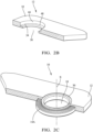
Fig. 2A shows a perspective view of an electrical contact insert according to some embodiments; -
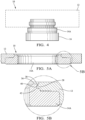
Fig. 2B shows a cross section perspective view of a bus bar of the bus bar assembly according to some embodiments; -
Fig. 2C shows an assembly view of the electrical contact insert ofFig. 2A and the bus bar ofFig. 2B according to some embodiments; -
Fig. 3A shows a bottom view of the electrical contact insert ofFig. 2A according to some embodiments; -
Fig. 3B shows a top view of the electrical contact insert ofFig. 2A according to some embodiments; -
Fig. 3C shows a partial cross section side view of the electrical contact insert ofFig. 2A according to some embodiments; -
Fig. 4 shows a side view of a bus bar assembly according to some embodiments; -
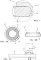
Fig. 5A is a cross section view of a bus bar assembly according to some embodiments; -
Fig. 5B is a close-up cross section view of a bus bar assembly according to some embodiments; -
Fig. 6A shows a perspective view of an electrical contact insert according to some embodiments; -
Fig. 6B shows a cross section perspective view of a bus bar of the bus bar assembly according to some embodiments; -
Fig. 6C shows an assembly view of the electrical contact insert ofFig. 6A and the bus bar ofFig. 6B according to some embodiments; -
Fig. 7 is a close-up cross section view of a bus bar assembly according to some embodiments; -
Fig. 8A is a top view of an electrical contact insert according to some embodiments; -
Fig. 8B is a side view of an electrical contact insert according to some embodiments; -
Fig. 8C is a side view of a process of attaching the contact insert ofFigs. 8A and 8B to a bus bar according to some embodiments; -
Figs. 9A to 9C are perspective views of electrical contact inserts according to some embodiments; -
Figs. 10A to 10C are perspective views of bus bar assemblies including electrical contact inserts ofFig. 9A to 9C according to some embodiments; -
Fig. 11A is a perspective view of bus bar assemblies including the electrical contact inserts ofFig. 9A to 9C according to some embodiments; -
Fig. 11B is a cross section view of the bus bar assemblies ofFig. 11A according to some embodiments; -
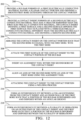
Fig. 12 is a flow chart of a method of manufacturing a bus bar assembly according to some embodiments. -
Fig 1 illustrates a non-limiting example of abus bar assembly 10. The bus bar assembly includes abus bar 12. Abus bar 12 is a bar or strip formed of a solid electrically conductive metal, e.g., a copper or aluminum-based alloy that is configured to carry high electrical currents, e.g., more than 100 amperes. Bus bars are typically used in high power electrical applications such as power stations, industrial power distributions, and electrical vehicles. Thebus bar assembly 10 also includes an electrical contact insert, hereinafter referred to as theinsert 14, that is configured to provide a mechanical and electrical connection feature between thebus bar 12 and anelectrical device 16, such as a battery or electric motor. Theinsert 14 is a formed piece of conductive copper material that has a greater hardness than the bus bar. - A first example of an
insert 14A is shown inFigs.2A-5B . Theinsert 14A has a cylindrical shape with a smooth through hole or bore 18 through the center of theinsert 14A that is configured to receive afastener 20, such as a bolt or threaded stud, to attach thebus bar assembly 10 to theelectrical device 16. Theinsert 14A may be used in bolted connections where a plated contact surface between thebus bar 12 and theelectrical device 16 is desired. Theinsert 14A is plated with an electrically conductive metallic material such as tin or silver, preferably only on adevice contact surface 22 which is the bottom surface as shown inFig. 2A ,Fig. 2C ,Fig. 3A , andFigs.4-5B . Thesmooth bore 18 allows thefastener 20 to easily pass through and avoids potential cross-threading issues that may occur with a threaded through hole. - This
insert 14A also includes acollar 24 that protrudes from a busbar contact surface 26 which is arranged generally opposite thedevice contact surface 22 is shown as the top surface of theinsert 14A inFig. 2A ,Fig. 2C ,Fig. 3A , andFigs.4-5B . Thecollar 24 has anannular groove 28 that defines stepped surfaces or levels around the perimeter of thecollar 24. - As can be seen in
Fig 2B , thebus bar 12 also has a cylindrical through hole or bore 30 extending through acontact portion 32 of thebus bar 12. Thebus bar 12 also defines acylindrical indentation 34 that surrounds the bus bar bore 30 and is coaxial with the bus bar bore 30. Thecollar 24 and theindentation 34 are sized such that they are in an interference or press fit condition when thecollar 24 is inserted within theindentation 34. Theannular groove 28 includes alip 36 extending over thegroove 28, thereby forming atop edge 38, aninner edge 40, and abottom edge 42 within thegroove 28. As can be seen inFig. 5A , diameter of thelip 36 is less than a diameter of thecollar 24. Thetop edge 38 is non-perpendicular to theinner edge 40 and non-parallel to thebottom edge 42. As shown inFigs. 5A and 5B , as thecollar 24 of theinsert 14A is pressed into theindentation 34, theside walls 44 of theindentation 34 in thebus bar 12 are deformed with at least some the material displaced from theside walls 44 entering and preferably filling thegroove 28 in thecollar 24, thereby securing theinsert 14A within theindentation 34. - The
device contact surface 22 also defines a plurality of alternating projections andindentations 46 that radially extend from thecollar 24. This plurality of alternating projections andindentations 46 displaces some of the material on thebottom surface 48 of theindentation 34, thereby inhibiting theinsert 14A from twisting within theindentation 34 when a torquing force is applied to thebus bar assembly 10, e.g., by thetreaded fastener 20 within thebore 18 of theinsert 14A. - A second example of an
insert 14B is shown inFigs.6A-7 . This insert also has a cylindrical shape with a smooth through hole or bore 18 through the center of theinsert 14B that is configured to receive afastener 20, such as a bolt or threaded stud, to attach thebus bar assembly 10 to theelectrical device 16. Theinsert 14B may be used in bolted connections where a plated contact surface between thebus bar 12 and theelectrical device 16 is desired. Theinsert 14B is plated with an electrically conductive metallic material such as tin or silver, preferably only on adevice contact surface 22 which is the bottom surface as shown inFig. 6A, Fig. 6C , andFig.7 . Thesmooth bore 18 allows thefastener 20 to easily pass through and avoids potential cross-threading issues that may occur with a threaded through hole. - The
insert 14B defines a plurality ofserrations 50 that protrudes from anouter edge 52 of theinsert 14B. The plurality ofserrations 50 is arranged at an angle on theouter edge 52 of theinsert 14B such that it is both non-parallel and non-perpendicular to an axis X of thebore 18 in theinsert 14B. - As can be seen in
Fig 6B , thebus bar 12 also has a cylindrical through hole or bore 30 extending through acontact portion 32 of thebus bar 12. Thebus bar 12 also defines acylindrical indentation 34 that surrounds the bus bar bore 30 and is coaxial with the bus bar bore 30. The plurality ofserrations 50 and theindentation 34 are sized such that they are in an interference or press fit condition when theinsert 14B is placed within theindentation 34. As shown inFigs. 5A and 5B , as theinsert 14B is pressed into theindentation 34, theside walls 44 of theindentation 34 in thebus bar 12 are deformed by the plurality ofserrations 50 with at least some the material displaced from theside walls 44 entering and preferably filling spaces between theserrations 50, thereby securing theinsert 14B within theindentation 34. In addition, the angled plurality ofserrations 50 causes theinsert 14B to rotate slightly as theinsert 14B is pressed into theindentation 34. - The plurality of
serrations 50 has sharp edges that provide broaching features that break through surface oxides on thebus bar 12 to improve electrical performance and mechanical retention. - The
device contact surface 22 also defines a plurality of alternating projections andindentations 46 in a busbar contact surface 26 which is arranged generally opposite thedevice contact surface 22 which is shown as the top surface of the insert inFig. 6A, Fig. 6C , andFig.7 . The plurality of alternating projections andindentations 46 radially extend from thebore 18. This plurality of alternating projections andindentations 46 displace some of the material on thebottom surface 48 of theindentation 34, thereby inhibiting theinsert 14B from twisting within theindentation 34 when a torquing force is applied to thebus bar assembly 10, e.g., by thetreaded fastener 20 within thebore 18 of theinsert 14B. - While the preceding examples of the
bus bar 12 show abore 18 extending through thebus bar 12 surrounded by anindentation 34, alternative embodiments of a bus bar may only have a bore extending with a uniform diameter through the count portion and the collar or serrations may deform the inner wall of the bore to secure the insert to the bus bar. - A third example of an
insert 14C is shown inFigs. 8A-8C . Theinsert 14C also has a cylindrical shape with a smooth through hole or bore 18 through the center of theinsert 14C that is configured to receive afastener 20, such as a bolt or threaded stud, to attach thebus bar assembly 10 to theelectrical device 16. Theinsert 14C may be used in bolted connections where a plated contact surface between thebus bar 12 and theelectrical device 16 is desired. Theinsert 14C is plated with an electrically conductive metallic material such as tin or silver, preferably only on aninner portion 56 of adevice contact surface 22 which is the top surface as shown inFigs. 8A-8C . Thesmooth bore 18 allows thefastener 20 to easily pass through and avoids potential cross-threading issues that may occur with a threaded through hole. - A bus
bar contact surface 26 of theinsert 14C is generally flat and is welded to acontact portion 32 of thebus bar 12 thereby mechanically and electrically connecting theinsert 14C to thecontact portion 32 of thebus bar 12. The welding is preferably performed using a tortional sonic welding process, However, other sonic welding, laser welding, resistance welding, spin welding, brazing, or soldering processes may also be used in some applications of the bus bar. The welding theinsert 14C to thecontact portion 32 also inhibits theinsert 14C from twisting when a torquing force is applied to thebus bar assembly 10, e.g., by atreaded fastener 20 within thebore 18 of theinsert 14C. - A fourth example of an
insert 14D is shown inFigs. 9A-9C . Theinsert 14D has a round or obround cylindrical shape with a smooth through hole or bore 18 through the center of theinsert 14D that is configured to receive afastener 20, such as a bolt or threaded stud, to attach thebus bar assembly 10 to theelectrical device 16. The bore may also have a round or obround shape. An outer surface of thecollar 18 defines a plurality ofserrations 60 that extend in a direction generally parallel to thebore 18. The plurality ofserrations 60 are sized such that they are in an interference or press fit condition when theinsert 14D is placed within the bus bar bore 30. As shown inFigs. 10A-10C , theinsert 14D is pressed into the bus bar bore 30, the side walls of the bus bar bore 30 are deformed by the plurality ofserrations 60 with at least some the material displaced from the side walls entering and preferably filling spaces between theserrations 60, thereby securing theinsert 14D within the bus bar bore 30. The plurality ofserrations 60 has sharp edges that provide broaching features that break through surface oxides in the bus bar bore 30 to improve electrical performance and mechanical retention. - The
insert 14D may be used in bolted connections, as shown inFigs. 11A and 11B , where a plated contact surface between thebus bar 12 and theelectrical device 16 is desired. Thesmooth bore 18 allows thefastener 20 to easily pass through and avoids potential cross-threading issues that may occur with a threaded through hole. - The
insert 14D may be mechanically pressed into the bus bar bore 30 to provide a friction fit or may be torsionally welded to thebus bar 12. -
Fig. 12 shows amethod 200 of manufacturing a bus bar assembly, such as thebus bar assembly 10 described above. Themethod 200 includes the following steps: -
STEP 202, PROVIDE A BUS BAR FORMED OF A FIRST ELECTRICALLY CONDUCTIVE MATERIAL HAVING A PLANAR CONTACT PORTION AND DEFINING A SMOOTH FIRST BORE EXTENDING THROUGH THE CONTACT PORTION, includes providing abus bar 12 formed of a first electrically conductive material having aplanar contact portion 32 and defining a smoothfirst bore 30 extending through thecontact portion 32 as shown inFigs. 2B and6B ; -
STEP 204, PROVIDE A CONTACT INSERT FORMED OF A SECOND ELECTRICALLY CONDUCTIVE MATERIAL THAT HAS A GREATER HARDNESS THAN THE FIRST ELECTRICALLY CONDUCTIVE MATERIAL, THE CONTACT INSERT DEFINING A FIRST SURFACE AND A SECOND SURFACE OPPOSITE THE FIRST SURFACE THAT IS PLATED WITH A THIRD ELECTRICALLY CONDUCTIVE MATERIAL DIFFERENT THAN THE SECOND ELECTRICALLY CONDUCTIVE MATERIAL AND DEFINING A SMOOTH SECOND BORE, includes providing acontact insert 14 formed of a second electrically conductive material that has a greater hardness than the first electrically conductive material. Thecontact insert 14 defines afirst surface 26 and asecond surface 22 opposite thefirst surface 26 that is plated with a third electrically conductive material that is different than the second electrically conductive material. Thecontact insert 14 defines a smoothsecond bore 18 extending therethrough as shown inFig. 1 ; -
STEP 206, ARRANGE THE CONTACT INSERT ON THE CONTACT PORTION SUCH THAT THE SECOND BORE IS COAXIAL WITH THE FIRST BORE, includes arranging thecontact insert 14 on thecontact portion 32 such that thesecond bore 18 is coaxial with thefirst bore 30 as shown inFig. 1 ; -
STEP 208, ATTACH THE FIRST SURFACE OF THE CONTACT INSERT TO THE CONTACT PORTION OF THE BUS BAR, includes attaching thefirst surface 26 of thecontact insert 14 to thecontact portion 32 of thebus bar 12 as shown inFig. 1 ; -
STEP 210, INSERT AN ALIGNMENT TOOL WITHIN THE SECOND BORE OF THE CONTACT INSERT, is an optional step that includes inserting analignment tool 58 within thesecond bore 18 of the contact insert 14C as shown inFig. 8C ; -
STEP 212, ALIGN AN AXIS OF THE SECOND BORE WITH AN AXIS OF THE FIRST BORE USING THE ALIGNMENT TOOL, is an optional step that includes aligning an axis X of thesecond bore 18 with an axis X of thefirst bore 30 using thealignment tool 58 as shown inFig. 8C ; -
STEP 214, ATTACH THE CONTACT INSERT TO THE CONTACT PORTION USING A WELDING PROCESS, is an optional process that includes attaching the contact insert 14C to thecontact portion 32 using a welding process as shown inFig. 8C . The welding process may be laser welding, resistance welding, spin welding, brazing, soldering, or sonic welding, and is preferably a torsional sonic welding process; -
STEP 216, FORM AN INTERFERENCE FIT BETWEEN A COLLAR EXTENDING FROM THE CONTACT INSERT AND AN INNER WALL OF THE FIRST BORE SUCH THAT A PORTION OF THE BUS BAR IS DEFORMED AND DISPOSED WITHIN AN ANNULAR GROOVE, is an optional step that includes forming an interference fit between acollar 18 of acontact insert 14A and aninner wall 44 of anindentation portion 34 of thefirst bore 30 such that a portion of thebus bar 12 is deformed and disposed within anannular groove 28 defined in thecollar 18, seeFigs 5A and 5B ; and -
STEP 218, FORM AN INTERFERENCE FIT BETWEEN A PLURALITY OF SERRATIONS ON AN OUTER EDGE OF THE CONTACT INSERT AND THE FIRST BORE SUCH THAT A PORTION OF THE BUS BAR IS DEFORMED AND DISPOSED BETWEEN THE PLURALITY OF SERRATIONS, is an optional step that includes forming an interference fit between the plurality ofserrations 50 on anouter edge 52 of thecontact insert 14B and anindentation portion 34 of thefirst bore 30 such that a portion of thebus bar 12 is deformed and disposed between the plurality ofserrations 50, seeFig. 7 . - While this invention has been described in terms of the preferred embodiments thereof, it is not intended to be so limited, but rather only to the extent set forth in the claims that follow. For example, the above-described embodiments (and/or aspects thereof) may be used in combination with each other. In addition, many modifications may be made to configure a situation or material to the teachings of the invention without departing from its scope. Dimensions, types of materials, orientations of the various components, and the number and positions of the various components described herein are intended to define parameters of certain embodiments and are by no means limiting and are merely prototypical embodiments.
- Many other embodiments and modifications within the spirit and scope of the claims will be apparent to those of skill in the art upon reviewing the above description. The scope of the invention should, therefore, be determined with reference to the following claims, along with the full scope of equivalents to which such claims are entitled.
- As used herein, 'one or more' includes a function being performed by one element, a function being performed by more than one element, e.g., in a distributed fashion, several functions being performed by one element, several functions being performed by several elements, or any combination of the above.
- It will also be understood that, although the terms first, second, etc. are, in some instances, used herein to describe various elements, these elements should not be limited by these terms. These terms are only used to distinguish one element from another. For example, a first contact could be termed a second contact, and, similarly, a second contact could be termed a first contact, without departing from the scope of the various described embodiments. The first contact and the second contact are both contacts, but they are not the same contact.
- The terminology used in the description of the various described embodiments herein is for the purpose of describing embodiments only and is not intended to be limiting. As used in the description of the various described embodiments and the appended claims, the singular forms "a", "an" and "the" are intended to include the plural forms as well, unless the context clearly indicates otherwise. It will also be understood that the term "and/or" as used herein refers to and encompasses all possible combinations of one or more of the associated listed items. It will be further understood that the terms "includes," "including," "comprises," and/or "comprising," when used in this specification, specify the presence of stated features, integers, steps, operations, elements, and/or components, but do not preclude the presence or addition of one or more other features, integers, steps, operations, elements, components, and/or groups thereof.
- As used herein, the term "if' is, optionally, construed to mean "when" or "upon" or "in response to determining" or "in response to detecting," depending on the context. Similarly, the phrase "if it is determined" or "if [a stated condition or event] is detected" is, optionally, construed to mean "upon determining" or "in response to determining" or "upon detecting [the stated condition or event]" or "in response to detecting [the stated condition or event]," depending on the context.
- Additionally, while terms of ordinance or orientation may be used herein these elements should not be limited by these terms. All terms of ordinance or orientation, unless stated otherwise, are used for purposes distinguishing one element from another, and do not denote any order of operations, direction or orientation unless stated otherwise.
Claims (15)
- A bus bar assembly (10), comprising:a bus bar (12) formed of a first electrically conductive material having a planar contact portion (32), wherein the bus bar (12) defines a first bore (18) extending through the contact portion (32); anda contact insert (14) formed of a second electrically conductive material that has a greater hardness than the first electrically conductive material, wherein the contact insert (14) defines a first surface (26) that is mechanically and electrically connected to the contact portion (32) of the bus bar (12) and wherein the contact insert (14) defines a second surface (22) plated with a third electrically conductive material different than the second electrically conductive material, and wherein the contact insert (14) defines a smooth second bore (30) coaxial with the first bore (18) and extending from the first surface (26) to the second surface (22).
- The bus bar assembly (10) according to claim 1, wherein an annular ring on the second surface (22) around the second bore (30) is plated.
- The bus bar assembly (10) according to claim 1 or 2, wherein the contact insert (14) defines a cylindrical collar (24) extending from the second surface (22) and defining an annular groove (28) therein and wherein the collar (24) is in an interference fit with an inner wall (44) of the first bore (18) such that a portion of the bus bar (12) is deformed and disposed within the annular groove (28).
- The bus bar assembly (10) according to claim 3, wherein the collar (24) includes a lip (36) extending over the groove (28).
- The bus bar assembly (10) according to claim 5, wherein a diameter of the lip (36) is less than a diameter of the collar (24).
- The bus bar assembly (10) according to any one of claims 3 to 5, wherein the second surface (22) defines a plurality of alternating projections and indentations (46) radially extending from the collar (24).
- The bus bar assembly (10) according to any one of claims 3 to 6, wherein the bus bar (12) defines a cylindrical indentation (34) in the contact portion (32) surrounding the first bore (18).
- The bus bar assembly (10) according to any one of claims 5 to 7, wherein the bus bar (12) defines a cylindrical indentation (34) in the contact portion (32) surrounding the first bore (18), wherein an outer surface of the contact located intermediate the first and second surfaces (26, 22) defines a plurality of serrations (50) extending from the outer surface, and wherein this plurality of serrations (50) in an interference fit with the indentation (34) such that a portion of the bus bar (12) is deformed and disposed between the plurality of serrations (50).
- The bus bar assembly (10) according to claim 8, wherein the plurality of serrations (50) is non-parallel to an axis (X) of the second bore (30) and are non-perpendicular to the axis (X) of the second bore (30).
- The bus bar assembly (10) according to claim 8 or 9, wherein the second surface (22) defines a plurality of alternating projections and indentations (46) radially extending from the second bore (30).
- The bus bar assembly (10) according to any one of the preceding claims, wherein the first surface (26) of the contact insert (14) is welded to the contact portion (32) of the bus bar (12).
- The bus bar assembly (10) according to any one of the preceding claims, wherein the contact insert (14) defines a cylindrical collar (24) extending from the contact portion (32) and defining a plurality of serrations (60) therein and wherein the collar (24) is in an interference fit with an inner wall of the first bore (18) such that a portion of the bus bar (12) is deformed and disposed within the plurality of serrations (60).
- The bus bar assembly (10) according to claim 12, wherein the plurality of serrations (60) extend along the collar (26) is a direction parallel to an axis (X) of the second bore (30).
- The bus bar assembly according to claim 12 or 13, wherein the collar (26) and the second bore (30) have an obround cylindrical shape.
- A method of manufacturing a bus bar assembly (10), comprising:providing a bus bar (12) formed of a first electrically conductive material having a planar contact portion (32) and defining a smooth first bore (18) extending through the contact portion (32);providing a contact insert (14) formed of a second electrically conductive material that has a greater hardness than the first electrically conductive material, the contact insert (14) defining a first surface (26) and a second surface (22) opposite the first surface (26) that is plated with a third electrically conductive material different than the second electrically conductive material and defining a smooth second bore (30);arranging the contact insert (14) on the contact portion (32) such that the second bore (30) is coaxial with the first bore (18); andmechanically and electrically attaching the first surface (26) of the contact insert (14) to the contact portion (32) of the bus bar (12).
Applications Claiming Priority (3)
| Application Number | Priority Date | Filing Date | Title |
|---|---|---|---|
| US202163226925P | 2021-07-29 | 2021-07-29 | |
| US202163270670P | 2021-10-22 | 2021-10-22 | |
| US17/852,854 US12237658B2 (en) | 2021-07-29 | 2022-06-29 | Bus bar assembly with plated electrical contact surface |
Publications (2)
| Publication Number | Publication Date |
|---|---|
| EP4125153A1 true EP4125153A1 (en) | 2023-02-01 |
| EP4125153B1 EP4125153B1 (en) | 2024-07-10 |
Family
ID=82656335
Family Applications (1)
| Application Number | Title | Priority Date | Filing Date |
|---|---|---|---|
| EP22186083.6A Active EP4125153B1 (en) | 2021-07-29 | 2022-07-20 | Bus bar assembly with plated electrical contact surface |
Country Status (3)
| Country | Link |
|---|---|
| US (1) | US12237658B2 (en) |
| EP (1) | EP4125153B1 (en) |
| CN (1) | CN115693231A (en) |
Cited By (2)
| Publication number | Priority date | Publication date | Assignee | Title |
|---|---|---|---|---|
| DE102022128989A1 (en) * | 2022-11-02 | 2024-05-02 | Te Connectivity Germany Gmbh | CONNECTING ARRANGEMENT AND METHOD FOR PRODUCING A CONNECTING ARRANGEMENT |
| DE102023119375A1 (en) * | 2023-07-21 | 2025-01-23 | iwis smart connect GmbH | busbar |
Families Citing this family (5)
| Publication number | Priority date | Publication date | Assignee | Title |
|---|---|---|---|---|
| JP7393395B2 (en) * | 2021-08-06 | 2023-12-06 | 矢崎総業株式会社 | Bus bar |
| JP2025122941A (en) * | 2024-02-09 | 2025-08-22 | 株式会社オートネットワーク技術研究所 | connector |
| DE102024112514A1 (en) * | 2024-05-03 | 2025-11-06 | Te Connectivity Solutions Gmbh | Electrically conductive contact arrangement, module connector, connection arrangement and method for mechanical fastening |
| DE102024131783A1 (en) * | 2024-10-31 | 2026-04-30 | One Mobility Autokabel Gmbh | Connection arrangement and method for producing a connection arrangement |
| DE102024131782A1 (en) * | 2024-10-31 | 2026-04-30 | One Mobility Autokabel Gmbh | Connection arrangement and method for producing a connection arrangement |
Citations (5)
| Publication number | Priority date | Publication date | Assignee | Title |
|---|---|---|---|---|
| DE102006050708A1 (en) * | 2006-10-24 | 2008-05-08 | Auto Kabel Managementgesellschaft Mbh | Electrical flat conductor for use in electric vehicle, has casing arranged in opening and connected with diameter of opening along its surface in adhesively-joined manner, where casing has flange expanded in radial direction |
| WO2013039043A1 (en) * | 2011-09-12 | 2013-03-21 | サンコール株式会社 | Crimping structure for metal materials, and bus bar using said crimping structure |
| EP3297095A1 (en) * | 2016-09-16 | 2018-03-21 | Siemens Aktiengesellschaft | Copper current rail |
| US20190131609A1 (en) * | 2016-04-08 | 2019-05-02 | Autonetworks Technologies, Ltd. | Electrical connection structure |
| WO2020169295A1 (en) * | 2019-02-20 | 2020-08-27 | Auto-Kabel Management Gmbh | Electrical conductor and method for producing an electrical conductor |
Family Cites Families (14)
| Publication number | Priority date | Publication date | Assignee | Title |
|---|---|---|---|---|
| US2017493A (en) * | 1933-12-26 | 1935-10-15 | John B Glowacki | Nut |
| US6328615B1 (en) * | 2000-03-02 | 2001-12-11 | Itt Manufacturing Enterprises, Inc. | Contact formed of joined pieces |
| JP3767810B2 (en) * | 2001-04-27 | 2006-04-19 | 株式会社ヨコオ | Spring connector |
| US6902434B2 (en) | 2002-07-23 | 2005-06-07 | Cooper Technologies Company | Battery fuse bus bar assembly |
| US8480419B2 (en) | 2009-01-06 | 2013-07-09 | GM Global Technology Operations LLC | Low inductance connector assembly |
| JP2012009411A (en) * | 2010-05-24 | 2012-01-12 | Japan Aviation Electronics Industry Ltd | Conductor connection washer, connection mechanism using it and method of manufacturing conductor connection washer |
| US9673547B2 (en) * | 2012-05-11 | 2017-06-06 | Autonetworks Technologies, Ltd. | Plated terminal for connector and terminal pair |
| US20150236439A1 (en) * | 2012-08-31 | 2015-08-20 | Autonetworks Technologies, Ltd. | Plated terminal for connector, and terminal pair |
| US9184530B2 (en) * | 2012-10-10 | 2015-11-10 | Amphenol Corporation | Direct connect orthogonal connection systems |
| US9680246B2 (en) * | 2013-06-10 | 2017-06-13 | Oriental Electro Plating Corporation | Method for manufacturing plated laminate, and plated laminate |
| JP5962707B2 (en) * | 2013-07-31 | 2016-08-03 | 三菱マテリアル株式会社 | Copper alloy for electronic / electric equipment, copper alloy plastic working material for electronic / electric equipment, manufacturing method of copper alloy plastic working material for electronic / electric equipment, electronic / electric equipment parts and terminals |
| JP5668814B1 (en) * | 2013-08-12 | 2015-02-12 | 三菱マテリアル株式会社 | Copper alloy for electronic and electrical equipment, copper alloy sheet for electronic and electrical equipment, parts for electronic and electrical equipment, terminals and bus bars |
| JP6330689B2 (en) * | 2015-02-19 | 2018-05-30 | 株式会社オートネットワーク技術研究所 | Electrical contact pair and connector terminal pair |
| CN211295477U (en) * | 2019-12-16 | 2020-08-18 | 九阳股份有限公司 | Food preparation machine convenient to charge |
-
2022
- 2022-06-29 US US17/852,854 patent/US12237658B2/en active Active
- 2022-07-20 EP EP22186083.6A patent/EP4125153B1/en active Active
- 2022-07-29 CN CN202210904396.7A patent/CN115693231A/en active Pending
Patent Citations (6)
| Publication number | Priority date | Publication date | Assignee | Title |
|---|---|---|---|---|
| DE102006050708A1 (en) * | 2006-10-24 | 2008-05-08 | Auto Kabel Managementgesellschaft Mbh | Electrical flat conductor for use in electric vehicle, has casing arranged in opening and connected with diameter of opening along its surface in adhesively-joined manner, where casing has flange expanded in radial direction |
| WO2013039043A1 (en) * | 2011-09-12 | 2013-03-21 | サンコール株式会社 | Crimping structure for metal materials, and bus bar using said crimping structure |
| US20190131609A1 (en) * | 2016-04-08 | 2019-05-02 | Autonetworks Technologies, Ltd. | Electrical connection structure |
| EP3297095A1 (en) * | 2016-09-16 | 2018-03-21 | Siemens Aktiengesellschaft | Copper current rail |
| WO2020169295A1 (en) * | 2019-02-20 | 2020-08-27 | Auto-Kabel Management Gmbh | Electrical conductor and method for producing an electrical conductor |
| US20220085523A1 (en) * | 2019-02-20 | 2022-03-17 | Auto-Kabel Management Gmbh | Electrical Conductor and Method for Producing an Electrical Conductor |
Cited By (2)
| Publication number | Priority date | Publication date | Assignee | Title |
|---|---|---|---|---|
| DE102022128989A1 (en) * | 2022-11-02 | 2024-05-02 | Te Connectivity Germany Gmbh | CONNECTING ARRANGEMENT AND METHOD FOR PRODUCING A CONNECTING ARRANGEMENT |
| DE102023119375A1 (en) * | 2023-07-21 | 2025-01-23 | iwis smart connect GmbH | busbar |
Also Published As
| Publication number | Publication date |
|---|---|
| US20230036434A1 (en) | 2023-02-02 |
| CN115693231A (en) | 2023-02-03 |
| EP4125153B1 (en) | 2024-07-10 |
| US12237658B2 (en) | 2025-02-25 |
Similar Documents
| Publication | Publication Date | Title |
|---|---|---|
| US12237658B2 (en) | Bus bar assembly with plated electrical contact surface | |
| US8791374B1 (en) | Snap-in electrical connector | |
| EP2937943B1 (en) | Socket contact | |
| CN113454849B (en) | Electrical conductors and methods for making electrical conductors | |
| EP1535366B1 (en) | Electrical connector | |
| US20220247041A1 (en) | Electrical busbar with alignment features | |
| CN107667451B (en) | Cable crimping connection system and assembly method thereof, fastening sleeve | |
| JPH05217613A (en) | Electric grounding connector, electric grounding connector assembly and mounting method of electric grounding connector assembly on electric conductive panel | |
| KR101834028B1 (en) | Electrical connection arrangement and electrical connecting element and rechargeable battery arrangement therefor | |
| US20200132102A1 (en) | Stamped housings to facilitate assembly and related methods | |
| US11437765B1 (en) | Snap-in electrical connector | |
| US9873392B2 (en) | Terminal connection assembly for vehicle power distribution device | |
| US9705296B1 (en) | Snap-in electrical connector | |
| WO2004098810A1 (en) | Process for joining together components | |
| EP3582327B1 (en) | Connection terminal and terminal connection structure | |
| US20240047929A1 (en) | Stamped and formed electrical contact and method of producing same | |
| US9818502B1 (en) | Commonized electrical grounding device | |
| US20250246836A1 (en) | Modular electrical terminal set with interchangeable connection terminals | |
| WO2005025005A1 (en) | Grounding element and method for grounding | |
| JP5063857B2 (en) | Battery terminal | |
| EP4636269A1 (en) | Washer and screw connection assembly | |
| JP2002124246A (en) | Battery connection terminal and method of manufacturing the same | |
| EP4668500A1 (en) | Floating connector | |
| JP2025146009A (en) | Crimp terminal | |
| US20230092717A1 (en) | Ferrule for a coaxial cable terminal having overlapping crimp wings |
Legal Events
| Date | Code | Title | Description |
|---|---|---|---|
| PUAI | Public reference made under article 153(3) epc to a published international application that has entered the european phase |
Free format text: ORIGINAL CODE: 0009012 |
|
| STAA | Information on the status of an ep patent application or granted ep patent |
Free format text: STATUS: THE APPLICATION HAS BEEN PUBLISHED |
|
| AK | Designated contracting states |
Kind code of ref document: A1 Designated state(s): AL AT BE BG CH CY CZ DE DK EE ES FI FR GB GR HR HU IE IS IT LI LT LU LV MC MK MT NL NO PL PT RO RS SE SI SK SM TR |
|
| STAA | Information on the status of an ep patent application or granted ep patent |
Free format text: STATUS: REQUEST FOR EXAMINATION WAS MADE |
|
| 17P | Request for examination filed |
Effective date: 20230217 |
|
| RAP3 | Party data changed (applicant data changed or rights of an application transferred) |
Owner name: APTIV TECHNOLOGIES LIMITED |
|
| RBV | Designated contracting states (corrected) |
Designated state(s): AL AT BE BG CH CY CZ DE DK EE ES FI FR GB GR HR HU IE IS IT LI LT LU LV MC MK MT NL NO PL PT RO RS SE SI SK SM TR |
|
| RIC1 | Information provided on ipc code assigned before grant |
Ipc: F16B 39/282 20060101ALN20231222BHEP Ipc: F16B 19/02 20060101ALN20231222BHEP Ipc: F16B 17/00 20060101ALN20231222BHEP Ipc: F16B 5/02 20060101ALN20231222BHEP Ipc: C23C 18/31 20060101ALN20231222BHEP Ipc: H01R 4/34 20060101ALN20231222BHEP Ipc: H01R 4/30 20060101ALN20231222BHEP Ipc: H01R 4/62 20060101ALI20231222BHEP Ipc: H01R 4/10 20060101AFI20231222BHEP |
|
| GRAP | Despatch of communication of intention to grant a patent |
Free format text: ORIGINAL CODE: EPIDOSNIGR1 |
|
| STAA | Information on the status of an ep patent application or granted ep patent |
Free format text: STATUS: GRANT OF PATENT IS INTENDED |
|
| RIC1 | Information provided on ipc code assigned before grant |
Ipc: F16B 39/282 20060101ALN20240109BHEP Ipc: F16B 19/02 20060101ALN20240109BHEP Ipc: F16B 17/00 20060101ALN20240109BHEP Ipc: F16B 5/02 20060101ALN20240109BHEP Ipc: C23C 18/31 20060101ALN20240109BHEP Ipc: H01R 4/34 20060101ALN20240109BHEP Ipc: H01R 4/30 20060101ALN20240109BHEP Ipc: H01R 4/62 20060101ALI20240109BHEP Ipc: H01R 4/10 20060101AFI20240109BHEP |
|
| RIC1 | Information provided on ipc code assigned before grant |
Ipc: F16B 39/282 20060101ALN20240122BHEP Ipc: F16B 19/02 20060101ALN20240122BHEP Ipc: F16B 17/00 20060101ALN20240122BHEP Ipc: F16B 5/02 20060101ALN20240122BHEP Ipc: C23C 18/31 20060101ALN20240122BHEP Ipc: H01R 4/34 20060101ALN20240122BHEP Ipc: H01R 4/30 20060101ALN20240122BHEP Ipc: H01R 4/62 20060101ALI20240122BHEP Ipc: H01R 4/10 20060101AFI20240122BHEP |
|
| INTG | Intention to grant announced |
Effective date: 20240205 |
|
| GRAJ | Information related to disapproval of communication of intention to grant by the applicant or resumption of examination proceedings by the epo deleted |
Free format text: ORIGINAL CODE: EPIDOSDIGR1 |
|
| STAA | Information on the status of an ep patent application or granted ep patent |
Free format text: STATUS: REQUEST FOR EXAMINATION WAS MADE |
|
| GRAS | Grant fee paid |
Free format text: ORIGINAL CODE: EPIDOSNIGR3 |
|
| STAA | Information on the status of an ep patent application or granted ep patent |
Free format text: STATUS: GRANT OF PATENT IS INTENDED |
|
| GRAP | Despatch of communication of intention to grant a patent |
Free format text: ORIGINAL CODE: EPIDOSNIGR1 |
|
| INTC | Intention to grant announced (deleted) | ||
| P01 | Opt-out of the competence of the unified patent court (upc) registered |
Effective date: 20240418 |
|
| RAP1 | Party data changed (applicant data changed or rights of an application transferred) |
Owner name: APTIV TECHNOLOGIES AG |
|
| RIC1 | Information provided on ipc code assigned before grant |
Ipc: F16B 39/282 20060101ALN20240423BHEP Ipc: F16B 19/02 20060101ALN20240423BHEP Ipc: F16B 17/00 20060101ALN20240423BHEP Ipc: F16B 5/02 20060101ALN20240423BHEP Ipc: C23C 18/31 20060101ALN20240423BHEP Ipc: H01R 4/34 20060101ALN20240423BHEP Ipc: H01R 4/30 20060101ALN20240423BHEP Ipc: H01R 4/62 20060101ALI20240423BHEP Ipc: H01R 4/10 20060101AFI20240423BHEP |
|
| INTG | Intention to grant announced |
Effective date: 20240510 |
|
| GRAA | (expected) grant |
Free format text: ORIGINAL CODE: 0009210 |
|
| STAA | Information on the status of an ep patent application or granted ep patent |
Free format text: STATUS: THE PATENT HAS BEEN GRANTED |
|
| AK | Designated contracting states |
Kind code of ref document: B1 Designated state(s): AL AT BE BG CH CY CZ DE DK EE ES FI FR GB GR HR HU IE IS IT LI LT LU LV MC MK MT NL NO PL PT RO RS SE SI SK SM TR |
|
| REG | Reference to a national code |
Ref country code: CH Ref legal event code: EP |
|
| REG | Reference to a national code |
Ref country code: DE Ref legal event code: R096 Ref document number: 602022004429 Country of ref document: DE |
|
| RAP4 | Party data changed (patent owner data changed or rights of a patent transferred) |
Owner name: APTIV TECHNOLOGIES AG |
|
| REG | Reference to a national code |
Ref country code: LT Ref legal event code: MG9D |
|
| REG | Reference to a national code |
Ref country code: NL Ref legal event code: MP Effective date: 20240710 |
|
| PG25 | Lapsed in a contracting state [announced via postgrant information from national office to epo] |
Ref country code: PT Free format text: LAPSE BECAUSE OF FAILURE TO SUBMIT A TRANSLATION OF THE DESCRIPTION OR TO PAY THE FEE WITHIN THE PRESCRIBED TIME-LIMIT Effective date: 20241111 |
|
| REG | Reference to a national code |
Ref country code: AT Ref legal event code: MK05 Ref document number: 1702873 Country of ref document: AT Kind code of ref document: T Effective date: 20240710 |
|
| PG25 | Lapsed in a contracting state [announced via postgrant information from national office to epo] |
Ref country code: NL Free format text: LAPSE BECAUSE OF FAILURE TO SUBMIT A TRANSLATION OF THE DESCRIPTION OR TO PAY THE FEE WITHIN THE PRESCRIBED TIME-LIMIT Effective date: 20240710 |
|
| PG25 | Lapsed in a contracting state [announced via postgrant information from national office to epo] |
Ref country code: PT Free format text: LAPSE BECAUSE OF FAILURE TO SUBMIT A TRANSLATION OF THE DESCRIPTION OR TO PAY THE FEE WITHIN THE PRESCRIBED TIME-LIMIT Effective date: 20241111 Ref country code: NL Free format text: LAPSE BECAUSE OF FAILURE TO SUBMIT A TRANSLATION OF THE DESCRIPTION OR TO PAY THE FEE WITHIN THE PRESCRIBED TIME-LIMIT Effective date: 20240710 |
|
| PG25 | Lapsed in a contracting state [announced via postgrant information from national office to epo] |
Ref country code: NO Free format text: LAPSE BECAUSE OF FAILURE TO SUBMIT A TRANSLATION OF THE DESCRIPTION OR TO PAY THE FEE WITHIN THE PRESCRIBED TIME-LIMIT Effective date: 20241010 |
|
| PG25 | Lapsed in a contracting state [announced via postgrant information from national office to epo] |
Ref country code: GR Free format text: LAPSE BECAUSE OF FAILURE TO SUBMIT A TRANSLATION OF THE DESCRIPTION OR TO PAY THE FEE WITHIN THE PRESCRIBED TIME-LIMIT Effective date: 20241011 Ref country code: PL Free format text: LAPSE BECAUSE OF FAILURE TO SUBMIT A TRANSLATION OF THE DESCRIPTION OR TO PAY THE FEE WITHIN THE PRESCRIBED TIME-LIMIT Effective date: 20240710 Ref country code: FI Free format text: LAPSE BECAUSE OF FAILURE TO SUBMIT A TRANSLATION OF THE DESCRIPTION OR TO PAY THE FEE WITHIN THE PRESCRIBED TIME-LIMIT Effective date: 20240710 |
|
| PG25 | Lapsed in a contracting state [announced via postgrant information from national office to epo] |
Ref country code: BG Free format text: LAPSE BECAUSE OF FAILURE TO SUBMIT A TRANSLATION OF THE DESCRIPTION OR TO PAY THE FEE WITHIN THE PRESCRIBED TIME-LIMIT Effective date: 20240710 |
|
| PG25 | Lapsed in a contracting state [announced via postgrant information from national office to epo] |
Ref country code: LV Free format text: LAPSE BECAUSE OF FAILURE TO SUBMIT A TRANSLATION OF THE DESCRIPTION OR TO PAY THE FEE WITHIN THE PRESCRIBED TIME-LIMIT Effective date: 20240710 |
|
| PG25 | Lapsed in a contracting state [announced via postgrant information from national office to epo] |
Ref country code: AT Free format text: LAPSE BECAUSE OF FAILURE TO SUBMIT A TRANSLATION OF THE DESCRIPTION OR TO PAY THE FEE WITHIN THE PRESCRIBED TIME-LIMIT Effective date: 20240710 Ref country code: IS Free format text: LAPSE BECAUSE OF FAILURE TO SUBMIT A TRANSLATION OF THE DESCRIPTION OR TO PAY THE FEE WITHIN THE PRESCRIBED TIME-LIMIT Effective date: 20241110 |
|
| PG25 | Lapsed in a contracting state [announced via postgrant information from national office to epo] |
Ref country code: HR Free format text: LAPSE BECAUSE OF FAILURE TO SUBMIT A TRANSLATION OF THE DESCRIPTION OR TO PAY THE FEE WITHIN THE PRESCRIBED TIME-LIMIT Effective date: 20240710 |
|
| PG25 | Lapsed in a contracting state [announced via postgrant information from national office to epo] |
Ref country code: ES Free format text: LAPSE BECAUSE OF FAILURE TO SUBMIT A TRANSLATION OF THE DESCRIPTION OR TO PAY THE FEE WITHIN THE PRESCRIBED TIME-LIMIT Effective date: 20240710 Ref country code: RS Free format text: LAPSE BECAUSE OF FAILURE TO SUBMIT A TRANSLATION OF THE DESCRIPTION OR TO PAY THE FEE WITHIN THE PRESCRIBED TIME-LIMIT Effective date: 20241010 |
|
| PG25 | Lapsed in a contracting state [announced via postgrant information from national office to epo] |
Ref country code: RS Free format text: LAPSE BECAUSE OF FAILURE TO SUBMIT A TRANSLATION OF THE DESCRIPTION OR TO PAY THE FEE WITHIN THE PRESCRIBED TIME-LIMIT Effective date: 20241010 Ref country code: PL Free format text: LAPSE BECAUSE OF FAILURE TO SUBMIT A TRANSLATION OF THE DESCRIPTION OR TO PAY THE FEE WITHIN THE PRESCRIBED TIME-LIMIT Effective date: 20240710 Ref country code: NO Free format text: LAPSE BECAUSE OF FAILURE TO SUBMIT A TRANSLATION OF THE DESCRIPTION OR TO PAY THE FEE WITHIN THE PRESCRIBED TIME-LIMIT Effective date: 20241010 Ref country code: LV Free format text: LAPSE BECAUSE OF FAILURE TO SUBMIT A TRANSLATION OF THE DESCRIPTION OR TO PAY THE FEE WITHIN THE PRESCRIBED TIME-LIMIT Effective date: 20240710 Ref country code: IS Free format text: LAPSE BECAUSE OF FAILURE TO SUBMIT A TRANSLATION OF THE DESCRIPTION OR TO PAY THE FEE WITHIN THE PRESCRIBED TIME-LIMIT Effective date: 20241110 Ref country code: HR Free format text: LAPSE BECAUSE OF FAILURE TO SUBMIT A TRANSLATION OF THE DESCRIPTION OR TO PAY THE FEE WITHIN THE PRESCRIBED TIME-LIMIT Effective date: 20240710 Ref country code: GR Free format text: LAPSE BECAUSE OF FAILURE TO SUBMIT A TRANSLATION OF THE DESCRIPTION OR TO PAY THE FEE WITHIN THE PRESCRIBED TIME-LIMIT Effective date: 20241011 Ref country code: FI Free format text: LAPSE BECAUSE OF FAILURE TO SUBMIT A TRANSLATION OF THE DESCRIPTION OR TO PAY THE FEE WITHIN THE PRESCRIBED TIME-LIMIT Effective date: 20240710 Ref country code: ES Free format text: LAPSE BECAUSE OF FAILURE TO SUBMIT A TRANSLATION OF THE DESCRIPTION OR TO PAY THE FEE WITHIN THE PRESCRIBED TIME-LIMIT Effective date: 20240710 Ref country code: BG Free format text: LAPSE BECAUSE OF FAILURE TO SUBMIT A TRANSLATION OF THE DESCRIPTION OR TO PAY THE FEE WITHIN THE PRESCRIBED TIME-LIMIT Effective date: 20240710 Ref country code: AT Free format text: LAPSE BECAUSE OF FAILURE TO SUBMIT A TRANSLATION OF THE DESCRIPTION OR TO PAY THE FEE WITHIN THE PRESCRIBED TIME-LIMIT Effective date: 20240710 |
|
| PG25 | Lapsed in a contracting state [announced via postgrant information from national office to epo] |
Ref country code: LU Free format text: LAPSE BECAUSE OF NON-PAYMENT OF DUE FEES Effective date: 20240720 |
|
| PG25 | Lapsed in a contracting state [announced via postgrant information from national office to epo] |
Ref country code: LU Free format text: LAPSE BECAUSE OF NON-PAYMENT OF DUE FEES Effective date: 20240720 |
|
| REG | Reference to a national code |
Ref country code: DE Ref legal event code: R097 Ref document number: 602022004429 Country of ref document: DE |
|
| PG25 | Lapsed in a contracting state [announced via postgrant information from national office to epo] |
Ref country code: DK Free format text: LAPSE BECAUSE OF FAILURE TO SUBMIT A TRANSLATION OF THE DESCRIPTION OR TO PAY THE FEE WITHIN THE PRESCRIBED TIME-LIMIT Effective date: 20240710 Ref country code: RO Free format text: LAPSE BECAUSE OF FAILURE TO SUBMIT A TRANSLATION OF THE DESCRIPTION OR TO PAY THE FEE WITHIN THE PRESCRIBED TIME-LIMIT Effective date: 20240710 Ref country code: SM Free format text: LAPSE BECAUSE OF FAILURE TO SUBMIT A TRANSLATION OF THE DESCRIPTION OR TO PAY THE FEE WITHIN THE PRESCRIBED TIME-LIMIT Effective date: 20240710 |
|
| PG25 | Lapsed in a contracting state [announced via postgrant information from national office to epo] |
Ref country code: BE Free format text: LAPSE BECAUSE OF NON-PAYMENT OF DUE FEES Effective date: 20240731 Ref country code: EE Free format text: LAPSE BECAUSE OF FAILURE TO SUBMIT A TRANSLATION OF THE DESCRIPTION OR TO PAY THE FEE WITHIN THE PRESCRIBED TIME-LIMIT Effective date: 20240710 Ref country code: MC Free format text: LAPSE BECAUSE OF FAILURE TO SUBMIT A TRANSLATION OF THE DESCRIPTION OR TO PAY THE FEE WITHIN THE PRESCRIBED TIME-LIMIT Effective date: 20240710 |
|
| PG25 | Lapsed in a contracting state [announced via postgrant information from national office to epo] |
Ref country code: CZ Free format text: LAPSE BECAUSE OF FAILURE TO SUBMIT A TRANSLATION OF THE DESCRIPTION OR TO PAY THE FEE WITHIN THE PRESCRIBED TIME-LIMIT Effective date: 20240710 |
|
| PG25 | Lapsed in a contracting state [announced via postgrant information from national office to epo] |
Ref country code: SK Free format text: LAPSE BECAUSE OF FAILURE TO SUBMIT A TRANSLATION OF THE DESCRIPTION OR TO PAY THE FEE WITHIN THE PRESCRIBED TIME-LIMIT Effective date: 20240710 Ref country code: IT Free format text: LAPSE BECAUSE OF FAILURE TO SUBMIT A TRANSLATION OF THE DESCRIPTION OR TO PAY THE FEE WITHIN THE PRESCRIBED TIME-LIMIT Effective date: 20240710 |
|
| PLBE | No opposition filed within time limit |
Free format text: ORIGINAL CODE: 0009261 |
|
| STAA | Information on the status of an ep patent application or granted ep patent |
Free format text: STATUS: NO OPPOSITION FILED WITHIN TIME LIMIT |
|
| REG | Reference to a national code |
Ref country code: BE Ref legal event code: MM Effective date: 20240731 |
|
| 26N | No opposition filed |
Effective date: 20250411 |
|
| PG25 | Lapsed in a contracting state [announced via postgrant information from national office to epo] |
Ref country code: IE Free format text: LAPSE BECAUSE OF NON-PAYMENT OF DUE FEES Effective date: 20240720 |
|
| PG25 | Lapsed in a contracting state [announced via postgrant information from national office to epo] |
Ref country code: SE Free format text: LAPSE BECAUSE OF FAILURE TO SUBMIT A TRANSLATION OF THE DESCRIPTION OR TO PAY THE FEE WITHIN THE PRESCRIBED TIME-LIMIT Effective date: 20240710 |
|
| PGFP | Annual fee paid to national office [announced via postgrant information from national office to epo] |
Ref country code: DE Payment date: 20250618 Year of fee payment: 4 |
|
| PGFP | Annual fee paid to national office [announced via postgrant information from national office to epo] |
Ref country code: FR Payment date: 20250703 Year of fee payment: 4 |
|
| PG25 | Lapsed in a contracting state [announced via postgrant information from national office to epo] |
Ref country code: CY Free format text: LAPSE BECAUSE OF FAILURE TO SUBMIT A TRANSLATION OF THE DESCRIPTION OR TO PAY THE FEE WITHIN THE PRESCRIBED TIME-LIMIT; INVALID AB INITIO Effective date: 20220720 |
|
| REG | Reference to a national code |
Ref country code: CH Ref legal event code: H13 Free format text: ST27 STATUS EVENT CODE: U-0-0-H10-H13 (AS PROVIDED BY THE NATIONAL OFFICE) Effective date: 20260224 |
|
| PG25 | Lapsed in a contracting state [announced via postgrant information from national office to epo] |
Ref country code: HU Free format text: LAPSE BECAUSE OF FAILURE TO SUBMIT A TRANSLATION OF THE DESCRIPTION OR TO PAY THE FEE WITHIN THE PRESCRIBED TIME-LIMIT; INVALID AB INITIO Effective date: 20220720 |
|
| PG25 | Lapsed in a contracting state [announced via postgrant information from national office to epo] |
Ref country code: CH Free format text: LAPSE BECAUSE OF NON-PAYMENT OF DUE FEES Effective date: 20250731 |