EP4125102A1 - Tank enclosure for a transformer and transformer - Google Patents
Tank enclosure for a transformer and transformer Download PDFInfo
- Publication number
- EP4125102A1 EP4125102A1 EP21187996.0A EP21187996A EP4125102A1 EP 4125102 A1 EP4125102 A1 EP 4125102A1 EP 21187996 A EP21187996 A EP 21187996A EP 4125102 A1 EP4125102 A1 EP 4125102A1
- Authority
- EP
- European Patent Office
- Prior art keywords
- transformer
- containers
- container
- tank enclosure
- cylindrically shaped
- Prior art date
- Legal status (The legal status is an assumption and is not a legal conclusion. Google has not performed a legal analysis and makes no representation as to the accuracy of the status listed.)
- Withdrawn
Links
- 238000004804 winding Methods 0.000 claims abstract description 32
- 239000012809 cooling fluid Substances 0.000 claims description 6
- 230000005855 radiation Effects 0.000 description 4
- 230000005534 acoustic noise Effects 0.000 description 3
- 238000001816 cooling Methods 0.000 description 3
- 230000005611 electricity Effects 0.000 description 2
- 239000000463 material Substances 0.000 description 2
- 229910000746 Structural steel Inorganic materials 0.000 description 1
- 230000008878 coupling Effects 0.000 description 1
- 238000010168 coupling process Methods 0.000 description 1
- 238000005859 coupling reaction Methods 0.000 description 1
- 230000001066 destructive effect Effects 0.000 description 1
- 230000005404 monopole Effects 0.000 description 1
Images

Classifications
-
- H—ELECTRICITY
- H01—ELECTRIC ELEMENTS
- H01F—MAGNETS; INDUCTANCES; TRANSFORMERS; SELECTION OF MATERIALS FOR THEIR MAGNETIC PROPERTIES
- H01F27/00—Details of transformers or inductances, in general
- H01F27/02—Casings
-
- H—ELECTRICITY
- H01—ELECTRIC ELEMENTS
- H01F—MAGNETS; INDUCTANCES; TRANSFORMERS; SELECTION OF MATERIALS FOR THEIR MAGNETIC PROPERTIES
- H01F27/00—Details of transformers or inductances, in general
- H01F27/08—Cooling; Ventilating
- H01F27/10—Liquid cooling
- H01F27/12—Oil cooling
-
- H—ELECTRICITY
- H01—ELECTRIC ELEMENTS
- H01F—MAGNETS; INDUCTANCES; TRANSFORMERS; SELECTION OF MATERIALS FOR THEIR MAGNETIC PROPERTIES
- H01F30/00—Fixed transformers not covered by group H01F19/00
- H01F30/06—Fixed transformers not covered by group H01F19/00 characterised by the structure
- H01F30/12—Two-phase, three-phase or polyphase transformers
Definitions
- the present disclosure is related to a tank enclosure for a transformer.
- the present disclosure is further related to a corresponding transformer with such a tank enclosure.
- Transformers are used to transfer an input voltage of an electrical circuit to an output voltage for another electrical circuit.
- Transformers comprise an active part including windings which are closed in a tank. Due to vibrations caused by operation of a transformer noise occurs which might be perceived as an annoying hum. In this respect, it is a challenge to provide stable and reliable operation of a transformer and to keep operation noise low.
- Embodiments of the present disclosure relate to a tank enclosure for a transformer that enables secure and reliable operation of the transformer and contributes to keep operation noise low. Further embodiments of the present disclosure relate to a transformer including such a tank enclosure.
- a tank enclosure for a transformer comprises a first container, a second container and a third container.
- the containers are coupled with each other and each container is configured to enclosure a respective winding of an active part of the transformer.
- the containers each comprise a cover, a bottom and a wall. Each wall is arranged between its respective cover and bottom with respect to a corresponding longitudinal axis and each wall is cylindrically shaped with respect to its longitudinal axis.
- the cylindrically vibration deflection shapes and the 120 degree phase change of vibrations between the cylindrical container are specifically formed to create negative phase interference of acoustic waves in the surrounding air.
- the described operation noise reduction is also feasible using only two containers or using four or more containers with cylindrically shaped walls, respectively.
- the described tank enclosure may comprise only a first and a second container with cylindrically shaped walls configured to enclosure a first and a second winding of an active part of the transformer, respectively.
- the described tank enclosure can comprise four or more containers with respective cylindrically shaped walls to enclosure four or more windings of an active part of the transformer, respectively.
- the cylindrically shaped containers of the tank enclosure can set up a given destructive interference of acoustic waves of operation noises and thus enabling to reduce sound propagation noticeably.
- a distance between two longitudinal axes of adjacent containers is given depending on the dimensions of the windings of the active part of the transformer to be enclosed.
- the longitudinal axes also represent rotation axes or center axes of the respective containers, thus the aforementioned distance is also set between two adjacent container centers.
- the tank enclosure is configured to surround a transformer with a power rating of 42.7 MVA (megavoltampers).
- a corresponding distance between adjacent container centers can have a value of 1.2 m.
- the power rating of a transformer and/or its electronic structure other distances are possible, of course.
- the cylindrically shaped walls of two adjacent containers are formed such that they overlap in a predetermined projected manner.
- the containers are specifically designed to take into account the geometry of the windings to be enclosed therein.
- the containers may not comprise a complete cylindrical shape that has cylindrical walls which are self-contained. Rather, the containers of the tank enclosure comprise cylindrically shapes which presents a predominant section of a complete cylinder, respectively. These cylindrical sections are connected with each other by form-fit, material-fit and/or none-positive connection.
- the tank enclosure further comprises plate-shaped connection sections arranged between adjacent containers.
- the cylindrically shaped walls of two adjacent containers are connected by respective plate-shaped connection sections on both sides with respect to their longitudinal axes.
- cylindrically shaped walls of the containers can be formed in one piece.
- the walls of the containers can be connected using additional elements.
- the cylindrically shaped walls of the containers are formed with a given respective radius depending on a distance between the walls and the windings to be enclosed.
- the aforementioned distance presents a critical spacing between the containers walls and the inner part of the transformer which affects the vibration and acoustic wave propagation as well.
- the size or geometry of the cylindrically shaped containers can also be matched to the windings to be encloses in view of an advantageous spacing.
- a material and/or a thickness of the cylindrically shaped walls can be given to influence beneficially the operation noise emission.
- the tank enclosure is made from structural steel and has a thickness of 6 mm.
- the transformer its windings and/or further electronic structure other materials and/or thicknesses are possible, of course.
- the respective covers and/or bottoms of the containers are cylindrically shaped as well.
- a transformer for transferring electrical energy between electrical circuits comprises a transformer active part with windings configured to provide a respective given voltage rating, and an embodiment of the described tank enclosure such that the tank enclosure surrounds and encloses the windings in a predetermined manner.
- the transformer comprises a cooling fluid, for example an oil, that is disposed inside the tank enclosure such that the windings are embedded in the cooling fluid.
- the windings for example three separate ones, are mechanically coupled with the tank enclosure and vibrations due to operation of the transformer are transferred through the mechanical connections and the cooling fluid to the tank enclosure resulting in a reduced noise development due to the cylindrically shaped container walls.
- the transformer comprises an embodiment of the tank enclosure
- described features and characteristics of the tank enclosure are also disclosed with respect to the transformer and vice versa.
- the present disclosure comprises several aspects, wherein every feature described with respect to one of the aspects is also disclosed herein with respect to the other aspect, even if the respective feature is not explicitly mentioned in the context of the specific aspect.
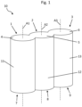
- FIG 1 illustrates an embodiment of a tank enclosure 10 for a transformer in a perspective view.
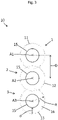
- the Figures 2 und 3 show a respective top or bottom view of the tank enclosure 10.
- the tank enclosure 10 comprises a first container 1, a second container 2 and a third container 3.
- the second container 2 is assembled between the first container 1 and the third container 3.
- the containers 1, 2, 3 are coupled with each other and each container 1, 2, 3 is configured to enclosure a respective winding 15 of an active part of the transformer (see Fig. 3 ).
- the containers 1, 2, 3 each comprise a cover 4, 5, 6, a bottom 7, 8, 9 and a wall 11, 12, 13.
- the walls 11, 12, 13 surrounds the windings 15 and are arranged between its respective cover 4, 5, 6 and bottom 7, 8, 9 with respect to a corresponding longitudinal axis A1, A2, A3.
- the covers 4, 5 and 6 of the containers 1, 2 and 3 are formed in one piece.
- the bottoms 7, 8 and 9 of the containers 1, 2 and 3 are formed in one piece as well.
- the walls 11, 12 and 13 of the containers 1, 2 and 3 can also be formed in one piece.
- the tank enclosure 10 may be formed from three pieces.
- Each wall 11, 12 and 13 is cylindrically shaped with respect to the respective longitudinal axis A1, A2 or A3.
- the longitudinal axes A1, A2, A3 also represent rotation axes or center axes of the respective containers 1, 2, 3, respectively.
- the walls 11, 12 and 13 form a lateral sheathing around the windings 15 with a given distance d therebetween (see Fig. 3 ).
- the center of two adjacent containers 1 and 2 or 2 and 3 which comply with the longitudinal axes A1, A2 and A3 are spaced apart by a given distance D which depends on the dimensions of the windings 15 of the active part of the transformer. This also applies to a radius R of each container 1, 2, 3 which defines the radial distance d.
- the tank enclosure 10 is configured to surround a transformer with a power rating of 42.7 MVA (megavoltampers).
- a corresponding distance D between adjacent container centers can have a value of 1-1.5m, for example 1.2 m.
- the radius R of the containers 1, 2, 3 can have a value of 50-70 cm, for example, and the distance d between the windings 15 and the container walls 11, 12, 13 can be set in a range of a few or several centimeters, for example.
- other distances D and/or d and/or radii R may be more applicable to minimize operation noise emission.
- the cylindrically shaped walls 11, 12, 13 of two adjacent containers 1 and 2 or 2 and 3 are connected by respective plate-shaped connection sections 14 (see Fig. 2 ).
- adjacent container walls 11, 12, 13 can be directly connected with each other in terms sheath intersections points of their respective cylindrical segment.
- the cylindrically shaped walls 11, 12, 13 of two adjacent containers 1, 2, 3 are configured to overlap in a predetermined projected manner (see doted lines in Fig. 3 ).
- the covers 4, 5, 6 and the bottoms 7, 8, 9 of the containers 1, 2, 3 are cylindrically shaped as well.
- the three windings 15 used for the three phase lines of three-phase electricity are embedded in a cooling oil 16 inside the tank enclosure 10 (see Fig. 3 ).
- the windings 15 are mechanically coupled with the tank enclosure 10 and vibrations due to operation of the transformer are transferred through the mechanical connections and the cooling oil 16 to the tank enclosure 10.
- the cylindrically vibration deflection shapes of the walls 11, 12, 13 comply with a 120 degree phase change of vibrations between the cylindrical container 1, 2, 3 are specifically formed to create negative phase interference of acoustic waves in the surrounding air. Accordingly, the transformer can operate and an operation noise can be reduced significantly.
- the transformer is configured to transfer electrical energy between electrical circuits and comprises an active part including the windings 15 to provide a respective given voltage rating.
- the tank enclosure 10 realizes a housing which on the one hand basically matches an inner shape of the active part and on the other hand is formed to reduce acoustic noise.
Landscapes
- Engineering & Computer Science (AREA)
- Power Engineering (AREA)
- Housings And Mounting Of Transformers (AREA)
Abstract
A tank enclosure (10) for a transformer comprises a first container (1), a second container (2) and a third container (3). The containers (1, 2, 3) are coupled with each other and each container (1, 2, 3) is configured to enclosure a respective winding (15) of an active part of the transformer. The containers (1, 2, 3) each comprise a cover (4, 5, 6), a bottom (7, 8, 9) and a wall (11, 12, 13), wherein each wall (11, 12, 13) is arranged between its respective cover (4, 5, 6) and bottom (7, 8, 9) with respect to a corresponding longitudinal axis (A1, A2, A3) and wherein each wall (11, 12, 13) is cylindrically shaped with respect to its longitudinal axis (A1, A2, A3).
Description
- The present disclosure is related to a tank enclosure for a transformer. The present disclosure is further related to a corresponding transformer with such a tank enclosure.
- Transformers are used to transfer an input voltage of an electrical circuit to an output voltage for another electrical circuit. Transformers comprise an active part including windings which are closed in a tank. Due to vibrations caused by operation of a transformer noise occurs which might be perceived as an annoying hum. In this respect, it is a challenge to provide stable and reliable operation of a transformer and to keep operation noise low.
- Embodiments of the present disclosure relate to a tank enclosure for a transformer that enables secure and reliable operation of the transformer and contributes to keep operation noise low. Further embodiments of the present disclosure relate to a transformer including such a tank enclosure.
- According to an embodiment, a tank enclosure for a transformer comprises a first container, a second container and a third container. The containers are coupled with each other and each container is configured to enclosure a respective winding of an active part of the transformer. The containers each comprise a cover, a bottom and a wall. Each wall is arranged between its respective cover and bottom with respect to a corresponding longitudinal axis and each wall is cylindrically shaped with respect to its longitudinal axis.
- Due to the described configuration a cylindrical shape low noise transformer tank design is feasible that enables a secure and reliable operation of the transformer and reduces an operation noise significantly.
- It is a recognition of the present disclosure that conventional designs of power transformer mostly comprise active parts is closed in a tank with rectangular shape and flat walls. Vibration that is generated by the active part is transferred through mechanical connections and oil coupling to a tank housing itself. The tank housing is later the source of vibrations and sound propagation resulting in an annoying hum.
- It is a further recognition of the present disclosure that such an operation noise that is generated by the transformer tank housing is strictly related to its vibration amplitude and radiation efficiency. The radiation efficiency depends on the vibration deflection shapes of the tank walls of the housing and varies depending on the design.
- By use of the described cylindrically shaped tank wall design it is possible to significantly reduce the radiation efficiency and thereby the emitted acoustic noise. The three windings are used because of three phase lines of three-phase electricity. Thus, the cylindrically vibration deflection shapes and the 120 degree phase change of vibrations between the cylindrical container are specifically formed to create negative phase interference of acoustic waves in the surrounding air.
- The described operation noise reduction is also feasible using only two containers or using four or more containers with cylindrically shaped walls, respectively. Thus, according to an embodiment the described tank enclosure may comprise only a first and a second container with cylindrically shaped walls configured to enclosure a first and a second winding of an active part of the transformer, respectively. According to a further embodiment the described tank enclosure can comprise four or more containers with respective cylindrically shaped walls to enclosure four or more windings of an active part of the transformer, respectively. In each case, the cylindrically shaped containers of the tank enclosure can set up a given destructive interference of acoustic waves of operation noises and thus enabling to reduce sound propagation noticeably.
- According to an embodiment of the tank enclosure a distance between two longitudinal axes of adjacent containers is given depending on the dimensions of the windings of the active part of the transformer to be enclosed. The longitudinal axes also represent rotation axes or center axes of the respective containers, thus the aforementioned distance is also set between two adjacent container centers. For example, the tank enclosure is configured to surround a transformer with a power rating of 42.7 MVA (megavoltampers). Thus, a corresponding distance between adjacent container centers can have a value of 1.2 m. However, depending on the power rating of a transformer and/or its electronic structure other distances are possible, of course.
- According to a further embodiment of the tank enclosure the cylindrically shaped walls of two adjacent containers are formed such that they overlap in a predetermined projected manner. Thus, the containers are specifically designed to take into account the geometry of the windings to be enclosed therein. The containers may not comprise a complete cylindrical shape that has cylindrical walls which are self-contained. Rather, the containers of the tank enclosure comprise cylindrically shapes which presents a predominant section of a complete cylinder, respectively. These cylindrical sections are connected with each other by form-fit, material-fit and/or none-positive connection.
- According to a further embodiment the tank enclosure further comprises plate-shaped connection sections arranged between adjacent containers. Thus, the cylindrically shaped walls of two adjacent containers are connected by respective plate-shaped connection sections on both sides with respect to their longitudinal axes.
- Moreover, the cylindrically shaped walls of the containers can be formed in one piece. Alternatively, the walls of the containers can be connected using additional elements.
- According to a further embodiment of the tank enclosure the cylindrically shaped walls of the containers are formed with a given respective radius depending on a distance between the walls and the windings to be enclosed. The aforementioned distance presents a critical spacing between the containers walls and the inner part of the transformer which affects the vibration and acoustic wave propagation as well. Thus, the size or geometry of the cylindrically shaped containers can also be matched to the windings to be encloses in view of an advantageous spacing. Moreover, a material and/or a thickness of the cylindrically shaped walls can be given to influence beneficially the operation noise emission. For instances, the tank enclosure is made from structural steel and has a thickness of 6 mm. However, depending on the transformer, its windings and/or further electronic structure other materials and/or thicknesses are possible, of course.
- According to a further embodiment of the tank enclosure the respective covers and/or bottoms of the containers are cylindrically shaped as well.
- According to an embodiment, a transformer for transferring electrical energy between electrical circuits comprises a transformer active part with windings configured to provide a respective given voltage rating, and an embodiment of the described tank enclosure such that the tank enclosure surrounds and encloses the windings in a predetermined manner. Moreover, the transformer comprises a cooling fluid, for example an oil, that is disposed inside the tank enclosure such that the windings are embedded in the cooling fluid. The windings, for example three separate ones, are mechanically coupled with the tank enclosure and vibrations due to operation of the transformer are transferred through the mechanical connections and the cooling fluid to the tank enclosure resulting in a reduced noise development due to the cylindrically shaped container walls.
- As a result of that the transformer comprises an embodiment of the tank enclosure, described features and characteristics of the tank enclosure are also disclosed with respect to the transformer and vice versa. Thus, the present disclosure comprises several aspects, wherein every feature described with respect to one of the aspects is also disclosed herein with respect to the other aspect, even if the respective feature is not explicitly mentioned in the context of the specific aspect.
- Exemplary embodiments are explained in the following with the aid of schematic drawings and reference numbers. The figures show:
- Figure 1
- an embodiment of a tank enclosure for a transformer in a perspective view,
- Figure 2
- the embodiment of the tank enclosure according to
figure 1 in a top view, and - Figure 3
- the embodiment of the tank enclosure according to the
figures 1 and2 in a further top view. - The accompanying figures are included to provide a further understanding. It is to be understood that the embodiments shown in the figures are illustrative representations and are not necessarily drawn to scale. Identical reference numbers designate elements or components with identical functions. In so far as elements or components correspond to one another in terms of their function in different figures, the description thereof is not repeated for each of the following figures. For the sake of clarity elements might not appear with corresponding reference symbols in all figures possibly.
-
Figure 1 illustrates an embodiment of atank enclosure 10 for a transformer in a perspective view. TheFigures 2 und3 show a respective top or bottom view of thetank enclosure 10. - The
tank enclosure 10 comprises afirst container 1, asecond container 2 and athird container 3. Thesecond container 2 is assembled between thefirst container 1 and thethird container 3. Thecontainers container Fig. 3 ). - The
containers cover bottom wall walls windings 15 and are arranged between itsrespective cover bottom covers containers bottoms containers walls containers tank enclosure 10 may be formed from three pieces. - Each
wall respective containers - The
walls windings 15 with a given distance d therebetween (seeFig. 3 ). Moreover, the center of twoadjacent containers windings 15 of the active part of the transformer. This also applies to a radius R of eachcontainer - For example, the
tank enclosure 10 is configured to surround a transformer with a power rating of 42.7 MVA (megavoltampers). Thus, a corresponding distance D between adjacent container centers can have a value of 1-1.5m, for example 1.2 m. The radius R of thecontainers windings 15 and thecontainer walls - The cylindrically shaped
walls adjacent containers Fig. 2 ). Alternatively,adjacent container walls walls adjacent containers Fig. 3 ). - Moreover, the
covers bottoms containers - By use of the described and illustrated cylindrically shaped tank wall design it is possible to significantly reduce a radiation efficiency and thereby an emitted acoustic noise during operation of the transformer. The three
windings 15 used for the three phase lines of three-phase electricity are embedded in a coolingoil 16 inside the tank enclosure 10 (seeFig. 3 ). Thewindings 15 are mechanically coupled with thetank enclosure 10 and vibrations due to operation of the transformer are transferred through the mechanical connections and the coolingoil 16 to thetank enclosure 10. - Due to the specific cylindrically shaped
walls walls cylindrical container - The transformer is configured to transfer electrical energy between electrical circuits and comprises an active part including the
windings 15 to provide a respective given voltage rating. Thetank enclosure 10 realizes a housing which on the one hand basically matches an inner shape of the active part and on the other hand is formed to reduce acoustic noise. - The embodiment shown in the
figures 1 and2 as stated represent an exemplary embodiment of theimproved tank enclosure 10 for a transformer. Therefore, it does not constitute all embodiments. Actual arrangements may vary from the embodiment shown in the figures. -
- 1
- first container
- 2
- second container
- 3
- third container
- 4
- cover of the first container
- 5
- cover of the second container
- 6
- cover of the third container
- 7
- bottom of the first container
- 8
- bottom of the second container
- 9
- bottom of the third container
- 10
- tank enclosure
- 11
- cylindrically shaped wall of the first container
- 12
- cylindrically shaped wall of the second container
- 13
- cylindrically shaped wall of the third container
- 14
- straight connection section
- 15
- winding
- 16
- cooling oil
- A1
- axis of the first cylinder
- A2
- axis of the second cylinder
- A3
- axis of the third cylinder
- D
- distance between a winding and a wall of a container
- D
- distance between adjacent axes
- R
- radius of the cylindrically shaped wall
- L
- longitudinal axis of the vacuum interrupter assembly
Claims (8)
- A tank enclosure (10) for a transformer, comprising:- a first container (1),- a second container (2),- a third container (3), andwherein the containers (1, 2, 3) are coupled with each other and each container (1, 2, 3) is configured to enclosure a respective winding (15) of an active part of the transformer, and wherein the containers (1, 2, 3) each comprise a cover (4, 5, 6), a bottom (7, 8, 9) and a wall (11, 12, 13), wherein each wall (11, 12, 13) is arranged between its respective cover (4, 5, 6) and bottom (7, 8, 9) with respect to a corresponding longitudinal axis (A1, A2, A3) and wherein each wall (11, 12, 13) is cylindrically shaped with respect to the corresponding longitudinal axis (A1, A2, A3).
- The tank enclosure (10) according to claim 1, wherein a distance (D) between two longitudinal axes (A1, A2, A3) of adjacent containers (1, 2, 3) is given depending on the dimensions of the windings (15) of the active part of the transformer.
- The tank enclosure (10) according to claim 1 or 2, wherein the cylindrically shaped walls (11, 12, 13) of two adjacent containers (1, 2, 3) overlap in a predetermined projected manner.
- The tank enclosure (10) according to any one of the preceding claims, wherein the cylindrically shaped walls (11, 12, 13) of two adjacent containers (1, 2, 3) are connected by respective plate-shaped connection sections (14).
- The tank enclosure (10) according to any one of the preceding claims, wherein the cylindrically shaped walls (11, 12, 13) of the containers (1, 2, 3) are formed in one piece.
- The tank enclosure (10) according to any one of the preceding claims, wherein the cylindrically shaped walls (11, 12, 13) of the containers (1, 2, 3) are formed with a given radius (R) depending on a distance (d) between the walls (11, 12, 13) and the windings (15) to be enclosed.
- The tank enclosure (10) according to any one of the preceding claims, wherein the covers (4, 5, 6) and/or the bottoms (7, 8, 9) of the containers (1, 2, 3) are cylindrically shaped.
- A transformer for transferring electrical energy between electrical circuits, comprising:- a transformer active part with three windings (15) configured to provide a respective given voltage rating,- a cooling fluid (16), and- a tank enclosure (10) according to any one of the preceding claims that encloses the windings (15) and the cooling fluid (16) such that the windings (15) are embedded in cooling fluid (16) inside the tank enclosure (10).
Priority Applications (1)
| Application Number | Priority Date | Filing Date | Title |
|---|---|---|---|
| EP21187996.0A EP4125102A1 (en) | 2021-07-27 | 2021-07-27 | Tank enclosure for a transformer and transformer |
Applications Claiming Priority (1)
| Application Number | Priority Date | Filing Date | Title |
|---|---|---|---|
| EP21187996.0A EP4125102A1 (en) | 2021-07-27 | 2021-07-27 | Tank enclosure for a transformer and transformer |
Publications (1)
| Publication Number | Publication Date |
|---|---|
| EP4125102A1 true EP4125102A1 (en) | 2023-02-01 |
Family
ID=77103864
Family Applications (1)
| Application Number | Title | Priority Date | Filing Date |
|---|---|---|---|
| EP21187996.0A Withdrawn EP4125102A1 (en) | 2021-07-27 | 2021-07-27 | Tank enclosure for a transformer and transformer |
Country Status (1)
| Country | Link |
|---|---|
| EP (1) | EP4125102A1 (en) |
Citations (4)
| Publication number | Priority date | Publication date | Assignee | Title |
|---|---|---|---|---|
| JPS5498929A (en) * | 1978-01-20 | 1979-08-04 | Toshiba Corp | Transformer tank |
| JPS61135104A (en) * | 1984-12-06 | 1986-06-23 | Toshiba Corp | Transformer tank |
| JPH0935957A (en) * | 1995-07-19 | 1997-02-07 | Hitachi Ltd | Electrical equipment |
| CN202720994U (en) * | 2012-07-23 | 2013-02-06 | 河北高晶电器设备有限公司 | Three-phase voltage transformer |
-
2021
- 2021-07-27 EP EP21187996.0A patent/EP4125102A1/en not_active Withdrawn
Patent Citations (4)
| Publication number | Priority date | Publication date | Assignee | Title |
|---|---|---|---|---|
| JPS5498929A (en) * | 1978-01-20 | 1979-08-04 | Toshiba Corp | Transformer tank |
| JPS61135104A (en) * | 1984-12-06 | 1986-06-23 | Toshiba Corp | Transformer tank |
| JPH0935957A (en) * | 1995-07-19 | 1997-02-07 | Hitachi Ltd | Electrical equipment |
| CN202720994U (en) * | 2012-07-23 | 2013-02-06 | 河北高晶电器设备有限公司 | Three-phase voltage transformer |
Similar Documents
| Publication | Publication Date | Title |
|---|---|---|
| JP6715101B2 (en) | Vibration power generator, vibration power generation unit, vibration power generation module and electrical equipment | |
| EP1148522A2 (en) | Low noise and low loss reactor | |
| US4864548A (en) | Flextensional transducer | |
| US20130181668A1 (en) | Non-contact charging module and non-contact charging instrument | |
| US20210118607A1 (en) | Winding arrangement for use in magnetic devices | |
| JP5212074B2 (en) | Electromagnetic equipment | |
| US20250125701A1 (en) | Vibration actuator | |
| JP2023163729A (en) | Vibration actuators and electrical equipment | |
| JP6663762B2 (en) | Linear vibration motor | |
| CN114583901B (en) | Mechatronic unit | |
| JP2018157094A (en) | Three-phase reactor with insulating structure | |
| JP2018018926A (en) | Coil unit | |
| CN211377858U (en) | Vibration motor | |
| JP2013183151A (en) | Stationary induction apparatus | |
| CN219943501U (en) | Integrated window type electromagnetic sound wave generator | |
| JP6049073B2 (en) | Electronics | |
| JP2013165576A (en) | Power transmission coil | |
| JP2015069977A (en) | Stationary induction apparatus | |
| JP6443358B2 (en) | Coil unit | |
| US2713127A (en) | Variable position transducer | |
| EP4492412A1 (en) | Transformer | |
| KR20180001472U (en) | Angular vibration motor | |
| US20250023392A1 (en) | Wireless power receiver device | |
| EP3796765A1 (en) | Power converting system and battery charger with improved thermal dissipation | |
| KR101333055B1 (en) | A generator and a manufactuing method the same |
Legal Events
| Date | Code | Title | Description |
|---|---|---|---|
| PUAI | Public reference made under article 153(3) epc to a published international application that has entered the european phase |
Free format text: ORIGINAL CODE: 0009012 |
|
| STAA | Information on the status of an ep patent application or granted ep patent |
Free format text: STATUS: THE APPLICATION HAS BEEN PUBLISHED |
|
| AK | Designated contracting states |
Kind code of ref document: A1 Designated state(s): AL AT BE BG CH CY CZ DE DK EE ES FI FR GB GR HR HU IE IS IT LI LT LU LV MC MK MT NL NO PL PT RO RS SE SI SK SM TR |
|
| STAA | Information on the status of an ep patent application or granted ep patent |
Free format text: STATUS: THE APPLICATION IS DEEMED TO BE WITHDRAWN |
|
| 18D | Application deemed to be withdrawn |
Effective date: 20230802 |