EP4125045A2 - Verfahren und system zur erzeugung eines 3d-netzes einer szene unter verwendung einer rgbd-bildsequenz - Google Patents
Verfahren und system zur erzeugung eines 3d-netzes einer szene unter verwendung einer rgbd-bildsequenz Download PDFInfo
- Publication number
- EP4125045A2 EP4125045A2 EP22177444.1A EP22177444A EP4125045A2 EP 4125045 A2 EP4125045 A2 EP 4125045A2 EP 22177444 A EP22177444 A EP 22177444A EP 4125045 A2 EP4125045 A2 EP 4125045A2
- Authority
- EP
- European Patent Office
- Prior art keywords
- mesh
- planar
- point cloud
- rgbd
- images
- Prior art date
- Legal status (The legal status is an assumption and is not a legal conclusion. Google has not performed a legal analysis and makes no representation as to the accuracy of the status listed.)
- Granted
Links
Images




Classifications
-
- G—PHYSICS
- G06—COMPUTING OR CALCULATING; COUNTING
- G06T—IMAGE DATA PROCESSING OR GENERATION, IN GENERAL
- G06T17/00—Three-dimensional [3D] modelling for computer graphics
- G06T17/20—Finite element generation, e.g. wire-frame surface description, tesselation
-
- G—PHYSICS
- G06—COMPUTING OR CALCULATING; COUNTING
- G06T—IMAGE DATA PROCESSING OR GENERATION, IN GENERAL
- G06T7/00—Image analysis
- G06T7/10—Segmentation; Edge detection
- G06T7/11—Region-based segmentation
-
- G—PHYSICS
- G06—COMPUTING OR CALCULATING; COUNTING
- G06T—IMAGE DATA PROCESSING OR GENERATION, IN GENERAL
- G06T7/00—Image analysis
- G06T7/10—Segmentation; Edge detection
- G06T7/174—Segmentation; Edge detection involving the use of two or more images
-
- G—PHYSICS
- G06—COMPUTING OR CALCULATING; COUNTING
- G06T—IMAGE DATA PROCESSING OR GENERATION, IN GENERAL
- G06T7/00—Image analysis
- G06T7/30—Determination of transform parameters for the alignment of images, i.e. image registration
- G06T7/33—Determination of transform parameters for the alignment of images, i.e. image registration using feature-based methods
-
- G—PHYSICS
- G06—COMPUTING OR CALCULATING; COUNTING
- G06T—IMAGE DATA PROCESSING OR GENERATION, IN GENERAL
- G06T7/00—Image analysis
- G06T7/50—Depth or shape recovery
- G06T7/55—Depth or shape recovery from multiple images
-
- G—PHYSICS
- G06—COMPUTING OR CALCULATING; COUNTING
- G06T—IMAGE DATA PROCESSING OR GENERATION, IN GENERAL
- G06T7/00—Image analysis
- G06T7/70—Determining position or orientation of objects or cameras
-
- G—PHYSICS
- G06—COMPUTING OR CALCULATING; COUNTING
- G06T—IMAGE DATA PROCESSING OR GENERATION, IN GENERAL
- G06T2207/00—Indexing scheme for image analysis or image enhancement
- G06T2207/10—Image acquisition modality
- G06T2207/10016—Video; Image sequence
-
- G—PHYSICS
- G06—COMPUTING OR CALCULATING; COUNTING
- G06T—IMAGE DATA PROCESSING OR GENERATION, IN GENERAL
- G06T2207/00—Indexing scheme for image analysis or image enhancement
- G06T2207/10—Image acquisition modality
- G06T2207/10024—Color image
-
- G—PHYSICS
- G06—COMPUTING OR CALCULATING; COUNTING
- G06T—IMAGE DATA PROCESSING OR GENERATION, IN GENERAL
- G06T2207/00—Indexing scheme for image analysis or image enhancement
- G06T2207/10—Image acquisition modality
- G06T2207/10028—Range image; Depth image; 3D point clouds
-
- G—PHYSICS
- G06—COMPUTING OR CALCULATING; COUNTING
- G06T—IMAGE DATA PROCESSING OR GENERATION, IN GENERAL
- G06T2207/00—Indexing scheme for image analysis or image enhancement
- G06T2207/30—Subject of image; Context of image processing
- G06T2207/30244—Camera pose
-
- G—PHYSICS
- G06—COMPUTING OR CALCULATING; COUNTING
- G06T—IMAGE DATA PROCESSING OR GENERATION, IN GENERAL
- G06T2210/00—Indexing scheme for image generation or computer graphics
- G06T2210/56—Particle system, point based geometry or rendering
Definitions
- the disclosure herein generally relates to image processing, and, more particularly, to method and system for generating 3D mesh.
- Image/video processing to reconstruct 3-Dimensional (3D) scenes is a technique with a wide range of applications.
- One of the applications is in the field of robotics.
- robots With the advancement of Artificial Intelligence, robots are becoming usable for various complicated tasks. These robots enable a human to operate the robot from remote location. Both telepresence and teleoperation require a good structural representation of the scene to allow users for virtual navigation or manipulation on the remote environment. These robots find application in remote teacher/meeting/surveillance etc. Telepresence robots are in much demand for hospital setups to mitigate the physical communication of medical staffs with patients.
- the robot when a robot is deployed in a warehouse for automated inventory management, the robot is required to move around in the warehouse, identify an object being searched, and then perform pick and place operations as required.
- a processor implemented method of mesh surface reconstruction of a scene is provided.
- a sequence of RGBD images of the scene is fetched, via one or more hardware processors.
- a mesh representation of each of the plurality of images in the sequence of RGBD images is generated, via the one or more hardware processors.
- the mesh representation for each of the images is generated by executing the following steps: Initially, planar point cloud and non-planar point cloud are segregated from the image by performing a plane segregation on the image and using a depth map and pose information of the image.
- Object segmentation techniques can be used to extract point cloud corresponding to each non-planar object in the image. Further, a planar mesh is generated from the planar point cloud, and a non-planar mesh is generated for non-planar objects in the image. Further, the planar mesh and the non-planar mesh are merged to generate a combined mesh. This combined mesh acts as the mesh representation of each of the images. Further, a camera pose information is estimated by performing plane matching and pose estimation on each two consecutive images in the sequence of images via the one or more hardware processors. Further, an incremental merging of the generated mesh representation of the plurality of images is performed using the estimated camera pose information, to generate a representation of the scene captured in the sequence of RGBD images, via the one or more hardware processors.
- generating the planar mesh from the planar point cloud involves the following steps. Initially, a rotation matrix is calculated for each plane in the planar point cloud. Further, a 2-D image is obtained by aligning each of the planes in the planar point cloud parallel to an X-Y plane, by rotating each of the planes with respect to the X-Y plane based on values in the rotation matrix. Further, the planar mesh is obtained from the 2-D image. Also, the non-planar mesh is generated using the following steps. A point cloud of a non-planar object in the image is localized from the non-planar data. Further, a mesh is generated for the localized point cloud of the non-planar object, and boundary nodes and inner nodes of the mesh are segregated.
- the mesh has fixed number of nodes and known connectivity between the nodes. Further, a plurality of points in the point cloud of the object are segregated into boundary points and inner points, wherein for each of the boundary points nearest mesh node of the generated mesh is a boundary node and for each of the inner points nearest mesh node is an inner node. Further, the boundary nodes of the mesh near the boundary of the object are extended to connect with the boundary points of the object.
- a system for mesh surface reconstruction of a scene includes one or more hardware processors, an I/O interface, and a memory.
- the system then generates a mesh representation of each of the plurality of images in the sequence of RGBD images.
- the mesh representation for each of the images is generated by executing the following steps: Initially, planar point cloud and non-planar point cloud are segregated from the image by performing a plane segregation on the image and using a depth map and pose information of the image.
- Object segmentation techniques can be used to extract point cloud corresponding to each non-planar object in the image.
- a planar mesh is generated from the planar data, and a non-planar mesh is generated for each non-planar object in the image. Further, the planar mesh and the non-planar mesh are merged to generate a combined mesh. This combined mesh acts as the mesh representation of each of the images.
- a camera pose information is estimated by performing plane matching and pose estimation on each two consecutive images in the sequence of images. Further, an incremental merging of the generated mesh representation of the plurality of images is performed using the estimated camera pose information, to generate a representation of the scene captured in the sequence of RGBD images.
- the system generates the planar mesh from the planar point cloud involves the following steps. Initially, a rotation matrix is calculated for each plane in the planar point cloud.
- a 2-D image is obtained by aligning each of the planes in the planar data parallel to an X-Y plane, by rotating each of the planes with respect to the X-Y plane based on values in the rotation matrix.
- the planar mesh is obtained from the 2-D image.
- the system generates the non-planar mesh using the following steps.
- a point cloud of a non planar object in the image is localized from the image.
- a mesh is generated for the localized point cloud, and boundary nodes and inner nodes of the mesh are segregated.
- the mesh has fixed number of nodes and known connectivity between the nodes.
- a plurality of points in the point cloud of the object are segregated into boundary points and inner points, wherein for each of the boundary points nearest mesh node of the generated mesh is a boundary node and for each of the inner points nearest mesh node is an inner node. Further, the boundary nodes of the mesh near the boundary of the object are extended to connect with the boundary points of the object.
- a non-transitory computer readable medium for of mesh surface reconstruction of a scene.
- the non-transitory computer readable medium includes a plurality of instructions, which when executed, cause the one or more hardware processors to perform the following steps. Initially a sequence of RGBD images of the scene is fetched. Further, a mesh representation of each of the plurality of images in the sequence of RGBD images is generated. The mesh representation for each of the images is generated by executing the following steps: Initially, planar point cloud and non-planar point cloud are segregated from the image by performing a plane segregation on the image and using a depth map and pose information of the image. Object segmentation techniques can be used to extract point cloud corresponding to each non-planar object in the image.
- a planar mesh is generated from the planar point cloud, and a non-planar mesh is generated for non-planar objects in the image. Further, the planar mesh and the non-planar mesh are merged to generate a combined mesh. This combined mesh acts as the mesh representation of each of the images.
- a camera pose information is estimated by performing plane matching and pose estimation on each two consecutive images in the sequence of images. Further, an incremental merging of the generated mesh representation of the plurality of images is performed using the estimated camera pose information, to generate a representation of the scene captured in the sequence of RGBD images.
- generating the planar mesh from the planar point cloud involves the following steps. Initially, a rotation matrix is calculated for each plane in the planar point cloud.
- a 2-D image is obtained by aligning each of the planes in the planar point cloud parallel to an X-Y plane, by rotating each of the planes with respect to the X-Y plane based on values in the rotation matrix.
- the planar mesh is obtained from the 2-D image.
- the non-planar mesh is generated using the following steps. A point cloud of the non-planar object is localized from the image. Further, a mesh is generated for the localized point cloud, and boundary nodes and inner nodes of the mesh are segregated. The mesh has fixed number of nodes and known connectivity between the nodes.
- a plurality of points in the point cloud of the object are segregated into boundary points and inner points, wherein for each of the boundary points nearest mesh node of the generated mesh is a boundary node and for each of the inner points nearest mesh node is an inner node. Further, the boundary nodes of the mesh near the boundary of the object are extended to connect with the boundary points of the object.
- FIG. 1 through FIG. 8B where similar reference characters denote corresponding features consistently throughout the figures, there are shown preferred embodiments and these embodiments are described in the context of the following exemplary system and/or method.
- FIG. 1 illustrates an exemplary system for mesh surface reconstruction of a scene, according to some embodiments of the present disclosure.
- the system 100 includes a processor(s) 104, communication interface device(s), alternatively referred as input/output (I/O) interface(s) 106, and one or more data storage devices or a memory 102 operatively coupled to the processor(s) 104.
- the system 100 with one or more hardware processors is configured to execute functions of one or more functional blocks of the system 100.
- the processor(s) 104 can be one or more hardware processors 104.
- the one or more hardware processors 104 can be implemented as one or more microprocessors, microcomputers, microcontrollers, digital signal processors, central processing units, state machines, logic circuitries, and/or any devices that manipulate signals based on operational instructions.
- the one or more hardware processors 104 are configured to fetch and execute computer-readable instructions stored in the memory 102.
- the system 100 can be implemented in a variety of computing systems including laptop computers, notebooks, hand-held devices such as mobile phones, workstations, mainframe computers, servers, and the like.
- the I/O interface(s) 106 can include a variety of software and hardware interfaces, for example, a web interface, a graphical user interface to display the generated target images and the like and can facilitate multiple communications within a wide variety of networks N/W and protocol types, including wired networks, for example, LAN, cable, etc., and wireless networks, such as WLAN, cellular and the like.
- the I/O interface (s) 106 can include one or more ports for connecting to a number of external devices or to another server or devices.
- the memory 102 may include any computer-readable medium known in the art including, for example, volatile memory, such as static random access memory (SRAM) and dynamic random access memory (DRAM), and/or non-volatile memory, such as read only memory (ROM), erasable programmable ROM, flash memories, hard disks, optical disks, and magnetic tapes.
- volatile memory such as static random access memory (SRAM) and dynamic random access memory (DRAM)
- DRAM dynamic random access memory
- non-volatile memory such as read only memory (ROM), erasable programmable ROM, flash memories, hard disks, optical disks, and magnetic tapes.
- the memory 102 includes a database 108 that stores all data associated with the mesh surface reconstruction (alternately referred to as "mesh approximation") being performed by the system 100.
- the database 108 stores the configurable instructions that are executed to cause the one or more hardware processors 104 to perform various steps associated with the mesh surface reconstruction.
- the database 108 may further store all data that is collected as input for the purpose of the mesh surface reconstruction, data generated as intermediate results while reconstructing the mesh of a scene such as but not limited to planar and non-planar data extracted, planar meshes and non-planar meshes generated, and so on. Functions of the components of the system 100 are explained in conjunction with the flow diagrams in FIG. 2 through FIG. 5 , and the example figures in FIG. 6 and FIG. 7 .
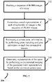
- FIG. 2 is a flow diagram depicting steps involved in the process of mesh surface reconstruction of a scene, using the system of FIG. 1 , according to some embodiments of the present disclosure.
- the system 100 fetches a sequence of RGBD images of a scene in which the image capturing means is deployed.
- the image capturing means may be associated with the robot, and the sequence of RGBD images capture area/location/objects in field of view of the image capturing means used by the robot(s).
- 'RGBD' type images being referred to in the embodiments disclosed herein are in state of the art RGBD format which captures colour information (RGB - 'Red Green Blue') as well as depth (D) information.
- the system 100 generates a mesh representation of each of the plurality of images in the sequence of RGBD images. Steps involved in the process of generating the mesh representation are depicted in process 300 depicted in FIG. 3 .
- Each of the RGBD images comprise planar point cloud as well as non-planar point cloud.
- Planar point cloud is for data/objects that lie in same plane, and the non-planar point cloud are the data/objects that do not lie in the same plane.
- the system 100 segregates the planar point cloud and non-planar point cloud, from each of the images in the RGBD image sequence, by performing a plane segmentation. At this step, a segmented plane is generated.
- planar and non-planar point clouds are generated from the segmented plane, non-planar objects identified, and pose information.
- the system 100 may use any suitable technique for the plane segmentation. For example, a concept of PlaneRCNN that uses mask R-CNN for plane detection and segmentation is used by the system 100. PlaneRCNN is capable of handling any number of planes, in comparison with other techniques such as but not limited to PlaneNet, and planeRecover, which need prior information on maximum number of planes. After performing the plane segmentation, the system 100 calculates various plane parameters using a suitable technique.
- a plane ⁇ is represented by [ q ⁇ , d ⁇ ] .
- q ⁇ is unit normal vector [ q x , q y , q z ] ⁇ IR 3 on a plane and d ⁇ ⁇ IR is distance of ⁇ from origin of the plane.
- the system 100 generates a planar mesh from the planar point cloud.
- Algorithmic representation of a sequence of steps used to generate the planar mesh from the planar point cloud is given below:
- the system 100 calculates a rotation matrix for each plane in the planar point cloud being processed.
- the system 100 then obtains a 2-D image by aligning each of the planes in the planar point cloud parallel to an X-Y plane, by rotating each of the planes with respect to the X-Y plane based on values in the rotation matrix. Further, the planar mesh is obtained from the 2-D image.
- algorithm 1 by controlling d grid , the system 100 controls quality of the generated mesh from coarse to finer.
- the system 100 generates a non-planar mesh from the non-planar point cloud.
- the non-planar point cloud may contain information on a plurality of the non-planar objects.
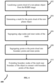
- the system 100 approximates object surface of each of these non-planar objects by executing process 400.
- the system 100 localizes a point cloud of each of the objects from the non-planar data, wherein the objects being referred to in the context of the non-planar mesh generation are non-planar objects.
- the point cloud for the object is generated by the system 100.
- the system 100 applies a suitable object segmentation method (such as RCNN) on the image, and the object segmentation method in return provides a mask of the object.
- the system 100 uses the mask to segment out the point cloud of the object, given the RGBD image sequence and pose of each of the images.
- the pose of the images may be estimated by using any suitable off-the-shelf Simultaneous Localization and Mapping (SLAM) technique.
- SLAM Simultaneous Localization and Mapping
- the system 100 generates a mesh for the fetched point cloud.
- the system 100 may use a suitable technique/algorithm such as Self Organizing Map (SOM).
- SOM Self Organizing Map
- the generated mesh contains a plurality of nodes, out of which, some are boundary nodes and the remaining are inner nodes.
- the number of nodes in the mesh may be fixed, and the nodes are connected through predefined set of connections.
- the system 100 segregates the boundary nodes and the inner nodes of the mesh.
- some points are boundary points and the rest are inner points.
- the boundary points are the points for which nearest mesh node is a boundary node, and the remaining points are inner points.
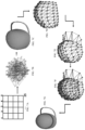
- the system 100 segregates the boundary points and the inner points of the point cloud. Further, at step 410, the system 100 extents the boundary nodes of the mesh near boundary of the object to connect with the boundary points of the object. The resulting mesh after extending the boundary nodes to connect with the boundary points of the object form the non-planar mesh. The system 100 controls extension of the boundary nodes of the mesh, by controlling learning rate and elasticity of the boundary nodes (as in steps 9 and 10 of Algorithm 2).
- x i acts as activation pattern.
- the nodes w j compete among each other, and a node emerges as winning node.
- the winning node i ( x ) learns the pattern of x i following a learning rate ⁇ ( n ) and cooperated with neighboring nodes for learning.
- h j,i ( x ) ( n ) exp (- d 2 /2 ⁇ 2 ( n )), where d is Euclidean distance between i ( x ) and j th node, ⁇ is spread, and ⁇ is epoch number.
- a number of epochs N arranges the nodes of the 2D lattice such that it covers surface of the object.
- the learning rate and the elasticity of the mesh nodes are controlled such that the boundary nodes move freely, almost independently of the inner nodes. This in turn helps to preserve shape of the mesh while extending the boundary nodes to cover the object.
- the step of covering the point cloud using the mesh is performed in multiple iterations. To accelerate the results, the system 100 may keep the learning rate and the spread high initially. The system 100 automatically determines the values of the learning rate and spread, at each iteration, using step 18 and step 19 of algorithm 2. Further, with each iteration, both the learning rate and the spread are decreased, so that the structure of the mesh obtained as a result of previous iterations is not diminished in subsequent iterations.
- the system 100 decreases value of ⁇ at a faster rate.
- ⁇ ( n ) 1 - exp (5( n - N) / N)
- ⁇ 0 and ⁇ N represent desired spread of neighborhood function at iteration 0 and iteration N respectively.
- the values of the learning rate and the spread are selected such that shape of the mesh and the inner nodes obtained after previous iterations are not affected.
- FIGS. 8A and 8B A comparison of decay functions used for used ⁇ and ⁇ in the process 200 and in conventional SOM technique is given in FIGS. 8A and 8B. It can be observed from FIGS. 8A and 8B that ⁇ decreases faster towards end of iterations, and value of ⁇ is less at a phase in which the mesh approximates a point cloud of the object.
- 'normal' for each point can be calculated using any suitable technique. Any abrupt change in normal along a 3D surface may indicate that the surface is not smooth, and is being referred to as 'sudden change in normal' in this context.
- , j 1,..., M ⁇ .
- a suitable technique for example, As-rigid-as-possible (ARAP) shape manipulation
- the system 100 merges the planar mesh and the non-planar mesh to generate a combined mesh.
- the combined mesh acts as a mesh representation of the image.
- the mesh representation is improved incrementally using point cloud information extracted from each of the images in the sequence of RGBD images.
- the system 100 estimates a camera pose information, by performing plane matching and pose estimation on each two consecutive images in the sequence of RGBD images.
- the camera pose information is estimated before mesh generation, so that the same can be used for generating the planar and non-planar point clouds.
- the system 100 matches planes between each two consecutive images in the sequence of RGBD images, based on the segregated planar point cloud, and based on the matching of planes, the system 100 determines a relative pose between the consecutive images.
- the system 100 generates a representation of the scene by performing an incremental merging of the generated mesh representation of the plurality of images in the sequence of RGBD images, based on the estimated camera pose information.
- the generated representation of the scene may be then used for various applications. For example, if the aforementioned application in robotics domain is considered, the generated representation of the scene may be used by the robots to perform navigation, and/or to identify objects in the scene and so on.
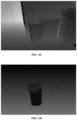
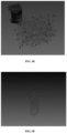
- the steps in process 200 are also depicted in the process flow diagram in FIG. 5 . In this process flow diagram, 'local mesh merging' refers to the step 308. Further, the steps in mesh approximation are depicted in the example figures 6A through 6F . 6A depicts input RGBD image.
- 6B depicts result of the segmentation of the planes in the input RGBD image.
- 6C depicts depth map of the input RGBD image.
- Point cloud of the object extracted from 6B and 6C of the input RGBD image is depicted in 6D.
- 6E shows initialization of the mesh nodes, and 6F shows approximated mesh/the mesh representation generated at step 208.
- steps in the process 200 may be performed in the same order as depicted in FIG. 2 or in any alternate order which is technically feasible. In another embodiment, one or more steps in the process 200 may be omitted.
- the embodiments of present disclosure herein addresses unresolved problem of mesh reconstruction of a scene.
- the embodiment thus provides a method and system for constructing planar mesh and non-planar mesh using planar point cloud and non-planar point cloud extracted from images of a scene.
- the embodiments herein further provide a mechanism of generating mesh representation of a scene, using the planar point cloud and non-planar point cloud from the images.
- the hardware device can be any kind of device which can be programmed including e.g. any kind of computer like a server or a personal computer, or the like, or any combination thereof.
- the device may also include means which could be e.g. hardware means like e.g. an application-specific integrated circuit (ASIC), a field-programmable gate array (FPGA), or a combination of hardware and software means, e.g.
- ASIC application-specific integrated circuit
- FPGA field-programmable gate array
- the means can include both hardware means and software means.
- the method embodiments described herein could be implemented in hardware and software.
- the device may also include software means.
- the embodiments may be implemented on different hardware devices, e.g. using a plurality of CPUs.
- the embodiments herein can comprise hardware and software elements.
- the embodiments that are implemented in software include but are not limited to, firmware, resident software, microcode, etc.
- the functions performed by various components described herein may be implemented in other components or combinations of other components.
- a computerusable or computer readable medium can be any apparatus that can comprise, store, communicate, propagate, or transport the program for use by or in connection with the instruction execution system, apparatus, or device.
- a computer-readable storage medium refers to any type of physical memory on which information or data readable by a processor may be stored.
- a computer-readable storage medium may store instructions for execution by one or more processors, including instructions for causing the processor(s) to perform steps or stages consistent with the embodiments described herein.
- the term "computer-readable medium” should be understood to include tangible items and exclude carrier waves and transient signals, i.e., be non-transitory. Examples include random access memory (RAM), read-only memory (ROM), volatile memory, nonvolatile memory, hard drives, CD ROMs, DVDs, flash drives, disks, and any other known physical storage media.
Landscapes
- Engineering & Computer Science (AREA)
- Physics & Mathematics (AREA)
- General Physics & Mathematics (AREA)
- Theoretical Computer Science (AREA)
- Computer Vision & Pattern Recognition (AREA)
- Computer Graphics (AREA)
- Geometry (AREA)
- Software Systems (AREA)
- Image Analysis (AREA)
- Image Processing (AREA)
Applications Claiming Priority (1)
| Application Number | Priority Date | Filing Date | Title |
|---|---|---|---|
| IN202121033776 | 2021-07-27 |
Publications (4)
| Publication Number | Publication Date |
|---|---|
| EP4125045A2 true EP4125045A2 (de) | 2023-02-01 |
| EP4125045A3 EP4125045A3 (de) | 2023-04-05 |
| EP4125045B1 EP4125045B1 (de) | 2025-11-26 |
| EP4125045C0 EP4125045C0 (de) | 2025-11-26 |
Family
ID=82258199
Family Applications (1)
| Application Number | Title | Priority Date | Filing Date |
|---|---|---|---|
| EP22177444.1A Active EP4125045B1 (de) | 2021-07-27 | 2022-06-07 | Verfahren und system zur erzeugung eines 3d-netzes einer szene unter verwendung einer rgbd-bildsequenz |
Country Status (2)
| Country | Link |
|---|---|
| US (1) | US11941760B2 (de) |
| EP (1) | EP4125045B1 (de) |
Cited By (1)
| Publication number | Priority date | Publication date | Assignee | Title |
|---|---|---|---|---|
| CN118470171A (zh) * | 2024-05-21 | 2024-08-09 | 华中科技大学 | 一种点云数据局部异常生成方法及系统 |
Families Citing this family (2)
| Publication number | Priority date | Publication date | Assignee | Title |
|---|---|---|---|---|
| CN119625286B (zh) * | 2025-02-11 | 2025-10-31 | 西北工业大学 | 一种基于梯度分解与对齐的增量目标检测方法 |
| CN119991759B (zh) * | 2025-04-17 | 2025-07-01 | 西安交通大学 | 一种点云配准方法、系统、设备及介质 |
Family Cites Families (4)
| Publication number | Priority date | Publication date | Assignee | Title |
|---|---|---|---|---|
| US8933925B2 (en) | 2009-06-15 | 2015-01-13 | Microsoft Corporation | Piecewise planar reconstruction of three-dimensional scenes |
| US10769848B1 (en) * | 2019-05-24 | 2020-09-08 | Adobe, Inc. | 3D object reconstruction using photometric mesh representation |
| US12001760B2 (en) * | 2019-08-30 | 2024-06-04 | Ansys, Inc. | Boundary-free periodic meshing method |
| US12026840B2 (en) * | 2021-05-21 | 2024-07-02 | Occipital, Inc. | System for generation of floor plans and three-dimensional models |
-
2022
- 2022-06-07 EP EP22177444.1A patent/EP4125045B1/de active Active
- 2022-06-16 US US17/807,339 patent/US11941760B2/en active Active
Cited By (1)
| Publication number | Priority date | Publication date | Assignee | Title |
|---|---|---|---|---|
| CN118470171A (zh) * | 2024-05-21 | 2024-08-09 | 华中科技大学 | 一种点云数据局部异常生成方法及系统 |
Also Published As
| Publication number | Publication date |
|---|---|
| US11941760B2 (en) | 2024-03-26 |
| EP4125045B1 (de) | 2025-11-26 |
| EP4125045C0 (de) | 2025-11-26 |
| EP4125045A3 (de) | 2023-04-05 |
| US20230063722A1 (en) | 2023-03-02 |
Similar Documents
| Publication | Publication Date | Title |
|---|---|---|
| EP4125045A2 (de) | Verfahren und system zur erzeugung eines 3d-netzes einer szene unter verwendung einer rgbd-bildsequenz | |
| CN112991447B (zh) | 一种动态环境下视觉定位与静态地图构建方法及系统 | |
| Wang et al. | Tracking partially-occluded deformable objects while enforcing geometric constraints | |
| US9715761B2 (en) | Real-time 3D computer vision processing engine for object recognition, reconstruction, and analysis | |
| EP3457357B1 (de) | Verfahren und systeme zur oberflächenanpassungsbasierten änderungsdetektion in einer 3d-punktwolke | |
| CN109697688B (zh) | 一种用于图像处理的方法和装置 | |
| Tung et al. | Self-supervised learning of motion capture | |
| CN114332415B (zh) | 基于多视角技术的输电线路廊道的三维重建方法及装置 | |
| TW202034215A (zh) | 利用視訊資料映射物件實體 | |
| AU2020200811A1 (en) | Direct meshing from multiview input using deep learning | |
| US11508098B2 (en) | Cross-device supervisory computer vision system | |
| US9286539B2 (en) | Constructing contours from imagery | |
| US12347141B2 (en) | Method and apparatus with object pose estimation | |
| CN117237431B (zh) | 深度估计模型的训练方法、装置、电子设备及存储介质 | |
| EP3761268A1 (de) | System und verfahren zur integration von objekten in monokulare slam | |
| US12033352B2 (en) | Methods and systems for generating end-to-end model to estimate 3-dimensional(3-D) pose of object | |
| US11367263B1 (en) | Image-guided three dimensional modeling | |
| US20200118333A1 (en) | Automated costume augmentation using shape estimation | |
| EP4224421A1 (de) | Vorrichtung und verfahren mit 3d-modellierung | |
| KR20240029850A (ko) | 3차원 공간 정보 생성 방법 및 장치 | |
| EP4446990B1 (de) | Verfahren und system zur schätzung zeitlich konsistenter menschlicher 3d-formen und -bewegungen aus monokularem video | |
| CN106940879B (zh) | 一种图像拼接方法及装置 | |
| Fu et al. | CBAM-SLAM: A semantic SLAM based on attention module in dynamic environment | |
| WO2014198029A1 (en) | Image completion based on patch offset statistics | |
| WO2011042371A1 (en) | Method of localizing landmark points in images |
Legal Events
| Date | Code | Title | Description |
|---|---|---|---|
| PUAI | Public reference made under article 153(3) epc to a published international application that has entered the european phase |
Free format text: ORIGINAL CODE: 0009012 |
|
| STAA | Information on the status of an ep patent application or granted ep patent |
Free format text: STATUS: THE APPLICATION HAS BEEN PUBLISHED |
|
| AK | Designated contracting states |
Kind code of ref document: A2 Designated state(s): AL AT BE BG CH CY CZ DE DK EE ES FI FR GB GR HR HU IE IS IT LI LT LU LV MC MK MT NL NO PL PT RO RS SE SI SK SM TR |
|
| PUAL | Search report despatched |
Free format text: ORIGINAL CODE: 0009013 |
|
| AK | Designated contracting states |
Kind code of ref document: A3 Designated state(s): AL AT BE BG CH CY CZ DE DK EE ES FI FR GB GR HR HU IE IS IT LI LT LU LV MC MK MT NL NO PL PT RO RS SE SI SK SM TR |
|
| RIC1 | Information provided on ipc code assigned before grant |
Ipc: G06T 17/20 20060101AFI20230228BHEP |
|
| STAA | Information on the status of an ep patent application or granted ep patent |
Free format text: STATUS: REQUEST FOR EXAMINATION WAS MADE |
|
| 17P | Request for examination filed |
Effective date: 20230630 |
|
| RBV | Designated contracting states (corrected) |
Designated state(s): AL AT BE BG CH CY CZ DE DK EE ES FI FR GB GR HR HU IE IS IT LI LT LU LV MC MK MT NL NO PL PT RO RS SE SI SK SM TR |
|
| GRAP | Despatch of communication of intention to grant a patent |
Free format text: ORIGINAL CODE: EPIDOSNIGR1 |
|
| STAA | Information on the status of an ep patent application or granted ep patent |
Free format text: STATUS: GRANT OF PATENT IS INTENDED |
|
| RIC1 | Information provided on ipc code assigned before grant |
Ipc: G06T 17/20 20060101AFI20250704BHEP Ipc: G06T 7/11 20170101ALI20250704BHEP Ipc: G06T 7/174 20170101ALI20250704BHEP Ipc: G06T 7/33 20170101ALI20250704BHEP Ipc: G06T 7/55 20170101ALI20250704BHEP |
|
| INTG | Intention to grant announced |
Effective date: 20250723 |
|
| GRAS | Grant fee paid |
Free format text: ORIGINAL CODE: EPIDOSNIGR3 |
|
| GRAA | (expected) grant |
Free format text: ORIGINAL CODE: 0009210 |
|
| STAA | Information on the status of an ep patent application or granted ep patent |
Free format text: STATUS: THE PATENT HAS BEEN GRANTED |
|
| AK | Designated contracting states |
Kind code of ref document: B1 Designated state(s): AL AT BE BG CH CY CZ DE DK EE ES FI FR GB GR HR HU IE IS IT LI LT LU LV MC MK MT NL NO PL PT RO RS SE SI SK SM TR |
|
| REG | Reference to a national code |
Ref country code: CH Ref legal event code: F10 Free format text: ST27 STATUS EVENT CODE: U-0-0-F10-F00 (AS PROVIDED BY THE NATIONAL OFFICE) Effective date: 20251126 Ref country code: GB Ref legal event code: FG4D |
|
| REG | Reference to a national code |
Ref country code: CH Ref legal event code: R17 Free format text: ST27 STATUS EVENT CODE: U-0-0-R10-R17 (AS PROVIDED BY THE NATIONAL OFFICE) Effective date: 20251127 |
|
| REG | Reference to a national code |
Ref country code: DE Ref legal event code: R096 Ref document number: 602022025486 Country of ref document: DE |
|
| REG | Reference to a national code |
Ref country code: IE Ref legal event code: FG4D |
|
| U01 | Request for unitary effect filed |
Effective date: 20251126 |
|
| U07 | Unitary effect registered |
Designated state(s): AT BE BG DE DK EE FI FR IT LT LU LV MT NL PT RO SE SI Effective date: 20251204 |
|
| PG25 | Lapsed in a contracting state [announced via postgrant information from national office to epo] |
Ref country code: ES Free format text: LAPSE BECAUSE OF FAILURE TO SUBMIT A TRANSLATION OF THE DESCRIPTION OR TO PAY THE FEE WITHIN THE PRESCRIBED TIME-LIMIT Effective date: 20251126 |
|
| PG25 | Lapsed in a contracting state [announced via postgrant information from national office to epo] |
Ref country code: NO Free format text: LAPSE BECAUSE OF FAILURE TO SUBMIT A TRANSLATION OF THE DESCRIPTION OR TO PAY THE FEE WITHIN THE PRESCRIBED TIME-LIMIT Effective date: 20260226 |
|
| PG25 | Lapsed in a contracting state [announced via postgrant information from national office to epo] |
Ref country code: HR Free format text: LAPSE BECAUSE OF FAILURE TO SUBMIT A TRANSLATION OF THE DESCRIPTION OR TO PAY THE FEE WITHIN THE PRESCRIBED TIME-LIMIT Effective date: 20251126 |
|
| PG25 | Lapsed in a contracting state [announced via postgrant information from national office to epo] |
Ref country code: RS Free format text: LAPSE BECAUSE OF FAILURE TO SUBMIT A TRANSLATION OF THE DESCRIPTION OR TO PAY THE FEE WITHIN THE PRESCRIBED TIME-LIMIT Effective date: 20260226 |
|
| PG25 | Lapsed in a contracting state [announced via postgrant information from national office to epo] |
Ref country code: IS Free format text: LAPSE BECAUSE OF FAILURE TO SUBMIT A TRANSLATION OF THE DESCRIPTION OR TO PAY THE FEE WITHIN THE PRESCRIBED TIME-LIMIT Effective date: 20260326 |
|
| PG25 | Lapsed in a contracting state [announced via postgrant information from national office to epo] |
Ref country code: PL Free format text: LAPSE BECAUSE OF FAILURE TO SUBMIT A TRANSLATION OF THE DESCRIPTION OR TO PAY THE FEE WITHIN THE PRESCRIBED TIME-LIMIT Effective date: 20251126 |