EP4124803B1 - Procédé de régulation d'un système de stockage et de chauffage thermodynamique - Google Patents
Procédé de régulation d'un système de stockage et de chauffage thermodynamique Download PDFInfo
- Publication number
- EP4124803B1 EP4124803B1 EP22181305.8A EP22181305A EP4124803B1 EP 4124803 B1 EP4124803 B1 EP 4124803B1 EP 22181305 A EP22181305 A EP 22181305A EP 4124803 B1 EP4124803 B1 EP 4124803B1
- Authority
- EP
- European Patent Office
- Prior art keywords
- heating
- domestic water
- storage tank
- temperature
- water
- Prior art date
- Legal status (The legal status is an assumption and is not a legal conclusion. Google has not performed a legal analysis and makes no representation as to the accuracy of the status listed.)
- Active
Links
Images



Classifications
-
- F—MECHANICAL ENGINEERING; LIGHTING; HEATING; WEAPONS; BLASTING
- F24—HEATING; RANGES; VENTILATING
- F24D—DOMESTIC- OR SPACE-HEATING SYSTEMS, e.g. CENTRAL HEATING SYSTEMS; DOMESTIC HOT-WATER SUPPLY SYSTEMS; ELEMENTS OR COMPONENTS THEREFOR
- F24D17/00—Domestic hot-water supply systems
- F24D17/02—Domestic hot-water supply systems using heat pumps
-
- F—MECHANICAL ENGINEERING; LIGHTING; HEATING; WEAPONS; BLASTING
- F24—HEATING; RANGES; VENTILATING
- F24D—DOMESTIC- OR SPACE-HEATING SYSTEMS, e.g. CENTRAL HEATING SYSTEMS; DOMESTIC HOT-WATER SUPPLY SYSTEMS; ELEMENTS OR COMPONENTS THEREFOR
- F24D19/00—Details
- F24D19/10—Arrangement or mounting of control or safety devices
- F24D19/1006—Arrangement or mounting of control or safety devices for water heating systems
- F24D19/1066—Arrangement or mounting of control or safety devices for water heating systems for the combination of central heating and domestic hot water
- F24D19/1072—Arrangement or mounting of control or safety devices for water heating systems for the combination of central heating and domestic hot water the system uses a heat pump
-
- F—MECHANICAL ENGINEERING; LIGHTING; HEATING; WEAPONS; BLASTING
- F24—HEATING; RANGES; VENTILATING
- F24D—DOMESTIC- OR SPACE-HEATING SYSTEMS, e.g. CENTRAL HEATING SYSTEMS; DOMESTIC HOT-WATER SUPPLY SYSTEMS; ELEMENTS OR COMPONENTS THEREFOR
- F24D3/00—Hot-water central heating systems
- F24D3/18—Hot-water central heating systems using heat pumps
-
- F—MECHANICAL ENGINEERING; LIGHTING; HEATING; WEAPONS; BLASTING
- F24—HEATING; RANGES; VENTILATING
- F24H—FLUID HEATERS, e.g. WATER OR AIR HEATERS, HAVING HEAT-GENERATING MEANS, e.g. HEAT PUMPS, IN GENERAL
- F24H15/00—Control of fluid heaters
- F24H15/20—Control of fluid heaters characterised by control inputs
- F24H15/212—Temperature of the water
- F24H15/223—Temperature of the water in the water storage tank
-
- F—MECHANICAL ENGINEERING; LIGHTING; HEATING; WEAPONS; BLASTING
- F24—HEATING; RANGES; VENTILATING
- F24H—FLUID HEATERS, e.g. WATER OR AIR HEATERS, HAVING HEAT-GENERATING MEANS, e.g. HEAT PUMPS, IN GENERAL
- F24H15/00—Control of fluid heaters
- F24H15/20—Control of fluid heaters characterised by control inputs
- F24H15/238—Flow rate
-
- F—MECHANICAL ENGINEERING; LIGHTING; HEATING; WEAPONS; BLASTING
- F24—HEATING; RANGES; VENTILATING
- F24H—FLUID HEATERS, e.g. WATER OR AIR HEATERS, HAVING HEAT-GENERATING MEANS, e.g. HEAT PUMPS, IN GENERAL
- F24H15/00—Control of fluid heaters
- F24H15/30—Control of fluid heaters characterised by control outputs; characterised by the components to be controlled
- F24H15/375—Control of heat pumps
- F24H15/38—Control of compressors of heat pumps
-
- F—MECHANICAL ENGINEERING; LIGHTING; HEATING; WEAPONS; BLASTING
- F24—HEATING; RANGES; VENTILATING
- F24H—FLUID HEATERS, e.g. WATER OR AIR HEATERS, HAVING HEAT-GENERATING MEANS, e.g. HEAT PUMPS, IN GENERAL
- F24H15/00—Control of fluid heaters
- F24H15/40—Control of fluid heaters characterised by the type of controllers
- F24H15/414—Control of fluid heaters characterised by the type of controllers using electronic processing, e.g. computer-based
- F24H15/421—Control of fluid heaters characterised by the type of controllers using electronic processing, e.g. computer-based using pre-stored data
- F24H15/429—Control of fluid heaters characterised by the type of controllers using electronic processing, e.g. computer-based using pre-stored data for selecting operation modes
-
- F—MECHANICAL ENGINEERING; LIGHTING; HEATING; WEAPONS; BLASTING
- F24—HEATING; RANGES; VENTILATING
- F24D—DOMESTIC- OR SPACE-HEATING SYSTEMS, e.g. CENTRAL HEATING SYSTEMS; DOMESTIC HOT-WATER SUPPLY SYSTEMS; ELEMENTS OR COMPONENTS THEREFOR
- F24D2220/00—Components of central heating installations excluding heat sources
- F24D2220/04—Sensors
- F24D2220/042—Temperature sensors
-
- F—MECHANICAL ENGINEERING; LIGHTING; HEATING; WEAPONS; BLASTING
- F24—HEATING; RANGES; VENTILATING
- F24D—DOMESTIC- OR SPACE-HEATING SYSTEMS, e.g. CENTRAL HEATING SYSTEMS; DOMESTIC HOT-WATER SUPPLY SYSTEMS; ELEMENTS OR COMPONENTS THEREFOR
- F24D2220/00—Components of central heating installations excluding heat sources
- F24D2220/04—Sensors
- F24D2220/044—Flow sensors
Definitions
- the present invention relates to a method for regulating a sanitary water storage and heating system for a sanitary water distribution installation.
- the document US2004/144528 A1 discloses such a method according to the preamble of claim 1.
- the invention relates to a method for regulating a storage and heating system comprising a thermodynamic heating device for heating domestic water present in the storage tank.
- This storage and heating system is for example a combined device for heating domestic water and heating water for a room, commonly called a "dual service heat pump”.
- thermodynamic heating device is a device whose operation is based on a thermodynamic loop, in which a compressor is connected to a condenser itself connected to an expansion valve, itself connected to an evaporator, which is connected to the compressor, which closes the loop.
- a working fluid circulates which is set in motion and compressed in the compressor, then undergoes condensation in the condenser before being expanded in the expansion valve and finally undergoes evaporation in the evaporator.
- the evaporator and the condenser are heat exchangers, in each of which the working fluid partially exchanges its thermal energy with another fluid.
- the evaporator allows a heat exchange between the working fluid and a cold source.
- This cold source is, for example, outside air in a so-called "air/water” heat pump. Outside air means air outside the building in which the heating device is installed or air from an unheated technical room inside this building.
- the water is heated by means of the condenser by the condensation of the working fluid which gives it its thermal energy.
- the domestic water can be heated directly by the condenser or indirectly via a fluid circuit between the condenser and a heat exchanger heating the domestic water.
- the fluid circuit can be a heating water circuit heated by the condenser and then heating the sanitary water of the storage system and heating.
- This heat exchanger of the storage and heating system is for example arranged outside or inside a water storage tank intended to supply hot water to a room.
- a temperature sensor is usually placed in the tank and is used to determine the level of hot domestic water.
- the temperature sensor is usually placed in a mid-position so as to be close to the interface between the volume of hot domestic water and the volume of cold domestic water.
- the exact position of the temperature sensor depends on the exact configuration of the storage and heating system.
- thermodynamic loop of the thermodynamic heating device is all the more important as the temperature of the volume of water present in the tank is low.
- the colder the water inside the tank the better the efficiency of the heating device.
- thermodynamic heating device starts the thermodynamic heating device causes the domestic water to be mixed over the entire height of the heat exchanger. If this volume of domestic water is partially hot when the thermodynamic heating device is started, this mixing will cause the temperature of the domestic water in contact with the heat exchanger to rise. The performance of the thermodynamic loop will therefore deteriorate. This deterioration in performance leads to an increase in energy consumption and therefore in cost for users.
- thermodynamic heating device It is therefore difficult to guarantee the needs of users, particularly in anticipation, while benefiting from satisfactory performance of the thermodynamic heating device.
- the ideal to guarantee the comfort of users would be to maintain the entire capacity of the tank at the set temperature in order to have a maximum reserve of hot sanitary water.
- This solution involves significant energy consumption and would require the thermodynamic loop to operate in conditions where it is not very efficient.
- the invention provides a method for regulating a domestic water storage and heating system according to claim 1.
- the body for determining information relating to the volume of domestic water entering the storage tank makes it possible to know precisely the volume of domestic water drawn and therefore the volume of hot domestic water remaining in the storage tank.
- the heating of the domestic water, therefore the start-up of the thermodynamic heating device, can thus be triggered only when the needs of the users require it.
- the information determined by the determining body may be indifferently relative to the volume of sanitary water entering or leaving the storage tank because these two volumes of sanitary water are identical.
- the temperature measuring device no longer has the function of detecting the level of hot sanitary water, as in the state of the art, but to indicate the temperature of the remaining volume of hot domestic water.
- This modification of the function of the temperature measuring device frees the constraints associated with its position in the storage tank. It is thus possible to move this temperature measuring device to improve the temperature measurement.
- the association of the information relating to the volume of sanitary water entering or leaving the storage tank with the temperature of the sanitary water makes it possible to know exactly the quantity of energy remaining in the storage tank. Indeed, it is possible to know whether a volume of remaining sanitary water is at 40°C or 55°C. For example, it is more interesting to have a volume of remaining sanitary water of 100L at 55°C than 100L at 40°C.
- the latter further comprises determining an outside air temperature for the domestic water storage and heating system, the heating of the domestic water being controlled by the controller also as a function of said outside air temperature.
- the rapid heating mode of domestic water can be triggered when the heating requirement is reduced.
- the storage and heating system may be any type of system comprising a thermodynamic heating device and a domestic hot water storage tank.
- the storage and heating system may be a thermodynamic water heater or a combined device for heating domestic hot water and heating water for a room, commonly called a "dual-service heat pump".
- the storage tank includes a sanitary water inlet and outlet intended to be connected to a sanitary water circuit.
- thermodynamic heating device is a heating device comprising a refrigeration circuit, i.e. a heat pump.
- the thermodynamic heating device comprises a compressor, a condenser, an expansion valve and an evaporator connected in series in a closed loop in which a working fluid circulates.
- Condensers and evaporators are heat exchangers.
- the working fluid receives its thermal energy with a cold source, for example the outside air.
- the working fluid provides its thermal energy with a hot source, here the domestic water present in the tank or intended to enter it.
- the condenser can heat the domestic water directly present in the storage tank or heat the domestic water upstream of the storage tank to then heat the domestic water.
- the heating of the domestic water in the storage tank can be carried out directly by the working fluid circulating in the heat pump or indirectly by using an intermediate fluid, eg heating water from a heating water circuit. The latter case is illustrated in the installation example of the figure 1 in which the heating water is used to heat the domestic water present in the tank.
- the condenser can be arranged inside or outside the storage tank.
- the condenser can have different geometries, including a plate exchanger or a helical exchanger.
- FIG. 1 An example of a sanitary water distribution installation comprising such a storage and heating system 11 is illustrated in figure 1 .
- the storage and heating system 11 is here a combined device 10 for heating domestic water and heating water for a room, commonly called a “dual-service heat pump”. This type of device is called a “heat pump”. "dual service heat” because the heating of the domestic water as well as the heating water is carried out via a single heat pump comprising a module intended to be placed outside the room. This heat pump corresponds to a thermodynamic heating device 13.
- the combined device 10 comprises a heating water circuit 18 connected to heating elements 20 of a room L, such as radiators.
- the combined device 10 also comprises a first heat exchanger 22 capable of exchanging heat between a heat transfer fluid circuit 24 and the heating water circuit 18.
- the heat transfer fluid circuit 24 exchanges heat between an environment E outside the room L and the heating water circuit 18 present inside the room L.
- an outdoor unit 25 is arranged at the level of the outdoor environment E and configured to exchange heat with the heat transfer fluid circuit 24.
- the outdoor unit 25, the heat transfer fluid circuit 24 and the first heat exchanger 22 form a heat pump capable of regulating the temperature of the heating water present in the heating water circuit 18. This heat pump forms the thermodynamic heating device 13.
- the combined device 10 also comprises a domestic hot water storage tank 14 and a domestic hot water circuit 12 in fluid communication with the storage tank 14.
- the domestic hot water circuit 12 is connected to domestic hot water distribution devices 16, such as taps.
- the storage tank 14 used in the combined device 10 forms an internal volume of 190 L, or 190 dm3.
- the combined device 10 further comprises a domestic water heating circuit 26 connected to the heating water circuit 18 in the form of a bypass. Thus, it is the heating water from the heating water circuit 18 which circulates in the domestic water heating circuit 26.
- This domestic water heating circuit 26 comprises a second heat exchanger 28 arranged inside the storage tank 14 to exchange heat with the domestic water present in the storage tank 14.
- This second heat exchanger 28 is a coil exchanger extending inside the storage tank 14 in the form of a helix.
- the configuration of this type of combined device 10 makes it possible to regulate the temperature of the heating water directly via the first exchanger 22.
- a three-way valve 30 arranged at a junction between the domestic hot water heating circuit 26 and the heating water circuit 18 makes it possible to selectively divert the heating water inside the domestic hot water heating circuit 26 to heat the domestic water present in the storage tank 14.
- the configuration of this type of combined device 10 makes it possible to regulate the temperature of the domestic water indirectly via the heating water.
- This indirect configuration of the heating of the domestic water involves a selective or alternating operation between the heating of the domestic water and the heating of the heating water. Indeed, under the action of the three-way valve 30 and a circulator 32, the heating water circulates either inside the heating water circuit 18 between the first heat exchanger 22 and the heating members 20 or inside the heating circuit of the domestic water 26 between the first 22 and the second 28 heat exchangers.
- FIG 2 presents a detailed example of a domestic hot water storage and heating system 11 that can be used in a combined device 10 in accordance with the figure 1 or in another sanitary water distribution installation.
- the storage tank 42 comprises a sanitary water inlet 50 and a sanitary water outlet 52.
- the sanitary water inlet 50 is intended to be connected to a sanitary water distribution network to bring cold sanitary water into the storage tank 42.
- the sanitary water outlet 52 is intended to be connected to a sanitary water circuit similar to the sanitary water circuit 12 of the figure 1 for distributing hot sanitary water to distribution points of a premises.
- the sanitary water inlet 50 comprises an inlet orifice arranged inside and in the lower part of the storage tank 42.
- the sanitary water outlet comprises a sanitary water outlet orifice arranged inside and in the upper part of the storage tank 42.
- the sanitary water inlet 50 and outlet 52 comprise for example at least two cannulas, the ends of which form the inlet and outlet orifices respectively.
- a heat exchanger 40 is configured to heat the domestic water of the storage tank 42.
- the heat exchanger 40 comprises an exchange body 44 connected to an exchanger inlet 46 and an exchanger outlet 48 to allow a fluid (here heating water) to circulate inside the exchange body 44 to transmit thermal energy to the domestic water present in the storage tank 42.
- the heat exchanger 40 extends over a portion of the height of the storage tank 42.
- the exchange body 44 is here arranged inside the storage tank 42 and has a helical shape. Alternatively, the exchange body 44 could be arranged outside the storage tank 42 and/or be of another shape.
- the storage and heating system 11 further comprises at least one temperature measuring member 54 for determining the temperature of the domestic water inside the storage tank 42.
- the temperature measuring member 54 is for example a temperature probe or a thermostat.
- the temperature measuring member 54 can be arranged inside the storage tank 42. In this case, the temperature measuring member 54 can be arranged in contact with the domestic water or without contact with the domestic water, for example by being arranged in a glove finger. Alternatively, the temperature measuring member 54 can be arranged outside the storage tank 42, for example in contact with a wall of the storage tank 42 or in contact with the domestic water outlet 52.
- the temperature measuring member 54 is preferably configured to measure the temperature of the domestic water present in the upper part of the storage tank 42. Thus, the temperature measuring member 54 makes it possible to determine more precisely the temperature of the domestic water near the domestic water outlet 52, and therefore the temperature of the domestic water delivered to the domestic water circuit for the users.
- the upper part of the storage tank 42 can be defined as follows. With reference to the figure 2 , the storage tank 42 defines in the operating position a storage height Hs along a vertical axis Y.
- the storage tank 42 in particular the internal cavity receiving the sanitary water, extends between a lower end Einf located at 0% of the storage height Hs and an upper end Esup located at 100% of the storage height Hs.
- the temperature measuring member 54 is arranged between 50 and 100% of the storage height Hs, preferably between 60 and 100% of the storage height Hs, more preferably between 80 and 100% of the storage height Hs.
- the temperature measuring member 54 is arranged at an upper wall of the storage tank 42, even external, or at the level of the sanitary water outlet 52, it is considered that the measuring member is arranged at 100% of the storage height Hs.
- the temperature measuring member 54 is also preferably arranged above the heat exchanger 40.
- the measuring member 54 is arranged above a mixing zone 56 corresponding to the internal volume of the storage tank over the entire height of the heat exchanger 40 along the vertical axis Y.
- the measurement of the temperature measuring member 54 is thus more reliable and therefore more representative of the temperature of the domestic water leaving via the domestic water outlet 52.
- the storage and heating system 11 may comprise a plurality of temperature measuring members 54. At least one of the temperature measuring members 54 is preferably arranged in the upper part of the storage tank 42 as described above. Another temperature member 54 may for example be arranged at a middle part of the storage tank 42 to determine the level of hot sanitary water. Determining the level of hot water corresponds to determining an interface 55 between the volume of cold sanitary water 56 located in the lower part of the storage tank 42 and the volume of hot sanitary water located in the upper part of this storage tank 42.
- the storage and heating system 11 further comprises a member for determining information relating to the volume of domestic water entering the storage tank 42.
- This determination member is for example a flow meter 58 configured to determine the flow rate of domestic water circulating between the domestic water inlet and outlet. It is thus possible to determine the volume of domestic water present in the storage tank 42 at any time.
- This flow meter can be placed at the sanitary water outlet 52. To limit the temperature of the sanitary water circulating through the flow meter and so to improve its longevity, it is advantageous to place the flow meter at the level of the sanitary water inlet 50.
- the storage and heating system 11 further comprises a controller 60 configured to control the heating of the domestic water by the thermodynamic heating device 13.
- the controller 60 is connected to the thermodynamic heating device 13 so as to be able to exchange control information.
- the controller 60 is connected to at least one compressor of the thermodynamic heating device 13 to control the starting or stopping of the compressor.
- the controller 60 is also connected to the determination member so as to receive information relating to the volume of domestic water entering the storage tank 42.
- the controller 60 is further connected to at least one temperature measuring member 54 so as to exchange information relating to the temperature of the domestic water.
- the controller 60 is in particular configured to control the heating of the domestic water by the thermodynamic heating device 13 as a function of the domestic water temperature and the information representative of the volume of domestic water entering the storage tank.
- the heating of the domestic water is thus controlled by the controller as a function of the temperature of the domestic water and the volume of water in the storage tank 42. It is thus possible to know precisely the volume of hot domestic water remaining and its temperature in the storage tank 42. This makes it possible not to restart heating of the domestic water too quickly as occurs when only the information relating to the temperature of the domestic water is used.
- This has the advantage of not stirring the water present in the storage tank, and therefore of reducing the performance of the thermodynamic heating device 13, while the volume of hot domestic water is still satisfactory. Heating is therefore required only when it is really necessary to meet user needs, and not in anticipation due to insufficiently precise information (temperature alone).
- thermodynamic heating device 13 This control is all the more precise, and therefore optimizes the performance of the thermodynamic heating device 13, as the temperature measuring member 54 is arranged in the upper part of the storage tank 42.
- the controller 60 is configured to determine an optimum heating time based on the temperature of the domestic water present in the storage tank and the information representative of the volume of domestic water entering the storage tank. It is thus possible to anticipate the time when heating is necessary to meet the needs of the users.
- the control can thus be predictive and determined based on a future need of a user. This future need can be information received by the controller 60 or determined by the latter based on the previous operation of the storage and heating system 11.
- the controller 60 can be configured to determine a future need of the users, for example a schedule, and control the heating of the domestic water so as to be able to provide a volume of domestic water at a predetermined set temperature for this schedule.
- the controller 60 may also be configured to determine the volume of domestic hot water remaining in the storage tank 42 as well as the temperature of this domestic hot water. In other words, the controller 60 may be configured to determine the amount of energy remaining in the storage tank 42.
- the controller 60 may also be configured to display or communicate this information to the user, for example in the form of a gauge representative of the state of charge of the storage tank 42 or an indicator providing information on the number of possible operations using domestic hot water (e.g. a number of showers).
- the controller 60 is configured to receive information relating to the temperature of the air outside the premises.
- the control of the heating is in this case determined according to this outside temperature to optimize the performance of the thermodynamic heating device 13.
- the heating can be carried out by taking into consideration the temperature of the outside air. The higher the front air temperature, the better the performance of the refrigeration circuit will be.
- the compressor of the thermodynamic heating device can also be variable speed.
- the control of the thermodynamic heating device 13 does not only concern the stopping or starting of the compressor but also the regulation of its rotation frequency. It is thus possible to control the heating of the domestic water more finely to benefit from better performance of the thermodynamic heating device 13.
- the controller 60 can thus be configured to control the heating of the domestic water according to at least two heating modes: a rapid heating mode and an extended heating mode.
- the rapid heating mode can be selected when the outside air temperature and/or the compressor speed reaches a critical threshold for optimizing the heating of the domestic water.
- This critical threshold value for optimizing the heating of the domestic water can be 2°C for the outside air temperature.
- the compressor speed is preferably high to accelerate the heating of the domestic water.
- a high compressor speed is for example greater than or equal to 80% of the maximum compressor power.
- the maximum rotation frequency of the compressor is preferably chosen.
- an extended heating mode can be selected when the outside air temperature and/or the compressor speed reaches an optimization threshold.
- This optimization threshold value can be 10°C for the outside air temperature.
- the compressor speed can be selected as low to benefit from the increased performance of the refrigeration circuit under these conditions.
- a low compressor speed is for example less than or equal to 60% of the maximum compressor power.
- thermodynamic heating device 13 when external conditions permit.
- the storage and heating system 11 may also comprise or be coupled to a fluid circuit for heating and/or cooling a room.
- This heating and/or cooling circuit is for example similar to the heating water circuit 18 of the figure 1 .
- the controller 60 can also be configured to determine an operating state of the heating and/or cooling fluid circuit of the premises. This operating state corresponds for example to an operating state of a circulator of the heating and/or cooling circuit, the state of a valve or even to a setpoint information transmitted by a user.
- the controller 60 is here configured to determine whether a heating or cooling mode of the premises is in progress or will be triggered.
- the controller 60 is also configured to control the thermodynamic heating device 13 as a function of the operating state of the heating and/or cooling circuit.
- the controller 60 is configured to trigger the extended domestic water heating mode as a function of the operating state of the heating and/or cooling circuit. If no heating or cooling command is in progress and a heating requirement is determined, the extended domestic water heating mode is required by the controller 60. Indeed, if there is no heating or cooling of the premises in progress, it is possible to achieve fully optimized domestic water heating, i.e. with a low compressor speed. Alternatively, only a heating command in progress can be determined, either because the thermodynamic heating device 13 does not have a cooling function or because it is accepted to reduce the cooling comfort of the cooling function to meet the domestic hot water requirement.
- the controller 60 can further be configured to provide a third mode of heating the domestic water: the progressive heating mode.
- This third heating mode is triggered when the outside air temperature and/or the compressor speed is between the critical and optimization threshold values, for example between 2°C and 10°C for the outside air temperature using the examples above.
- This progressive heating mode includes regulating the compressor rotation frequency according to the outside air temperature.
- the compressor rotation frequency is increased until the domestic water reaches a set temperature. This allows the compressor speed to be controlled as precisely as possible to benefit from the best performance of the refrigeration circuit.
- the domestic water is at a low or medium temperature at the start of heating, which allows heating to start at a low rotation frequency to reduce energy consumption. Then, the higher the domestic water temperature, the higher the compressor rotation frequency is to ensure that the domestic water temperature reaches the set value.
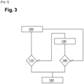
- FIG. 3 represents a flowchart illustrating an example of triggering a domestic water heater.
- FIG 4 represents a flowchart illustrating an example of determining the domestic water heating mode following the triggering of domestic water heating.
- the volume of sanitary water in the storage tank 42 is determined 100 by means of information relating to the volume of sanitary water in the storage tank 42.
- the controller 60 determines 110 whether the volume of sanitary water has reached a threshold value of sanitary water volume.
- This threshold value of water volume is for example set at 140L for a storage tank 42 having a capacity of 190L.
- the controller 60 triggers 120 the heating of the domestic water. Indeed, reaching the water volume threshold value indicates that a significant quantity of cold water has entered the storage tank 42.
- the controller 60 determines 130 the temperature of the domestic water in the tank. storage tank 42 by means of at least one temperature measuring member 54.
- this temperature is the temperature of the domestic water in the upper part of the storage tank 42 so as to have more precise information on the temperature of the domestic water delivered to the domestic water circuit.
- the controller 60 determines 140 whether the domestic hot water temperature has reached a domestic hot water temperature threshold value.
- This temperature threshold value is for example greater than or equal to 40°C.
- This temperature threshold value is preferably defined as a function of the position of the temperature member 54 considered for triggering the heating.
- the temperature threshold value is to estimate the actual temperature value delivered to the domestic hot water circuit.
- the temperature threshold value can thus be defined as close to the domestic hot water temperature setpoint desired by the users.
- the controller 60 triggers 120 the heating of the domestic water. Indeed, if the temperature threshold value has been reached, this means that the temperature of the domestic water is not satisfactory with respect to the set domestic water temperature.
- the domestic water heating is not triggered and the trigger determination process is reset. In fact, if the temperature threshold value is not reached, this means that the domestic water temperature is satisfactory with respect to the set domestic water temperature.
- a programmed or manual triggering of a domestic water heater can occur.
- a programmed triggering is, for example, a triggering planned at a time during the day or night.
- a manual triggering corresponds to a command from the user. The programmed or manual triggering replaces the process of determination of the triggering of domestic water heating described in connection with the figure 3 , even if the conditions for triggering domestic water heating are not met.
- the heating modes that can be triggered by the controller 60 are an extended heating mode 230, a rapid heating mode 240 and a progressive heating mode 250.
- This process is preferably implemented by the controller 60 following the triggering 120 of a domestic water heater.
- This triggering 120 can either come from the process of determining the figure 3 either a programmed or manual trigger.
- the controller 60 first begins by determining 200 whether the heating and/or cooling fluid circuit is in operation.
- rapid heating mode is triggered.
- the outside air temperature is determined 205.
- the controller 60 determines 210 whether the outside air temperature is greater than the optimization threshold value.
- the controller 60 triggers 230 the extended heating mode. Indeed, if the outside air temperature is higher than or equal to this optimization threshold value, the outside temperature conditions make it possible to benefit from good performance of the thermodynamic heating device 13.
- the compressor speed can be chosen as low to benefit from the increased performance of the refrigeration circuit under these conditions.
- the controller 60 determines 220 whether the outside air temperature has reached the critical threshold value for optimization.
- the controller 60 triggers 240 a rapid heating mode.
- the compressor speed is preferably high to accelerate the heating of the domestic water.
- the controller 60 triggers 250 the progressive heating mode.
- the process of determining the domestic water heating mode may be omitted from the determination step 200 when the storage and heating system is devoid of or is not coupled to a heating and/or cooling circuit.
- the determination process begins directly with the determination of the outside air temperature.
- the three modes of extended, rapid and progressive heating may also be implemented.
Landscapes
- Engineering & Computer Science (AREA)
- Physics & Mathematics (AREA)
- Thermal Sciences (AREA)
- Chemical & Material Sciences (AREA)
- Combustion & Propulsion (AREA)
- Mechanical Engineering (AREA)
- General Engineering & Computer Science (AREA)
- Computer Hardware Design (AREA)
- Fluid Mechanics (AREA)
- Heat-Pump Type And Storage Water Heaters (AREA)
Applications Claiming Priority (1)
| Application Number | Priority Date | Filing Date | Title |
|---|---|---|---|
| FR2108130A FR3125867B1 (fr) | 2021-07-27 | 2021-07-27 | Système de stockage et de chauffage thermodynamique à pilotage optimisé |
Publications (3)
| Publication Number | Publication Date |
|---|---|
| EP4124803A1 EP4124803A1 (fr) | 2023-02-01 |
| EP4124803C0 EP4124803C0 (fr) | 2024-08-14 |
| EP4124803B1 true EP4124803B1 (fr) | 2024-08-14 |
Family
ID=78332866
Family Applications (1)
| Application Number | Title | Priority Date | Filing Date |
|---|---|---|---|
| EP22181305.8A Active EP4124803B1 (fr) | 2021-07-27 | 2022-06-27 | Procédé de régulation d'un système de stockage et de chauffage thermodynamique |
Country Status (4)
| Country | Link |
|---|---|
| EP (1) | EP4124803B1 (pl) |
| ES (1) | ES2994371T3 (pl) |
| FR (1) | FR3125867B1 (pl) |
| PL (1) | PL4124803T3 (pl) |
Families Citing this family (1)
| Publication number | Priority date | Publication date | Assignee | Title |
|---|---|---|---|---|
| CN117267958A (zh) * | 2023-09-01 | 2023-12-22 | 广州市设计院集团有限公司 | 一种水箱容积的识别方法、装置、电子设备以及存储介质 |
Family Cites Families (3)
| Publication number | Priority date | Publication date | Assignee | Title |
|---|---|---|---|---|
| EP1475576A4 (en) * | 2002-02-12 | 2009-12-09 | Panasonic Corp | Heat pump water heater |
| FR2976347B1 (fr) * | 2011-06-08 | 2013-06-14 | Charot Ets | Procede de regulation d'un systeme de production d'eau chaude, unite de regulation et systeme de production d'eau chaude |
| EP4202316B1 (en) * | 2019-05-10 | 2024-08-07 | Mitsubishi Electric Corporation | Heat storage system |
-
2021
- 2021-07-27 FR FR2108130A patent/FR3125867B1/fr active Active
-
2022
- 2022-06-27 EP EP22181305.8A patent/EP4124803B1/fr active Active
- 2022-06-27 PL PL22181305.8T patent/PL4124803T3/pl unknown
- 2022-06-27 ES ES22181305T patent/ES2994371T3/es active Active
Also Published As
| Publication number | Publication date |
|---|---|
| ES2994371T3 (en) | 2025-01-22 |
| EP4124803C0 (fr) | 2024-08-14 |
| PL4124803T3 (pl) | 2025-01-07 |
| FR3125867B1 (fr) | 2023-11-24 |
| EP4124803A1 (fr) | 2023-02-01 |
| FR3125867A1 (fr) | 2023-02-03 |
Similar Documents
| Publication | Publication Date | Title |
|---|---|---|
| JP5073970B2 (ja) | ヒートポンプ給湯床暖房装置 | |
| EP2247897B1 (fr) | Installation de production d'eau chaude sanitaire | |
| WO2010090898A2 (en) | Apparatus and control method for a hybrid tankless water heater | |
| EP2729741A1 (fr) | Systeme d'echange thermique et procede de regulation d'une puissance thermique developpee par un tel systeme d'echange thermique | |
| EP4124803B1 (fr) | Procédé de régulation d'un système de stockage et de chauffage thermodynamique | |
| FR2995979A1 (fr) | Installation de chauffe-eau sanitaire a fonction de chauffage | |
| JP2010513840A (ja) | 貯蔵複合ボイラー | |
| EP3225922B1 (fr) | Systeme de rafraichissement, climatisation ou chauffage | |
| EP2603742B1 (fr) | Procédé et installation de régulation de température dans un bâtiment | |
| JP2008224076A (ja) | 給湯装置および給湯暖房装置 | |
| JP5828219B2 (ja) | コージェネレーションシステム、排熱利用装置、コージェネレーションシステムの制御方法及びヒートポンプ式給湯装置 | |
| CN113685886B (zh) | 采暖炉及其控制方法、控制装置 | |
| FR3074264A1 (fr) | Systeme de chauffage d’eau sanitaire | |
| EP1450109B1 (fr) | Installation solaire combinée comportant des moyens de gestion des surchauffes et procédé de contrôle de l'installation | |
| FR2976347A1 (fr) | Procede de regulation d'un systeme de production d'eau chaude, unite de regulation et systeme de production d'eau chaude | |
| WO2010043829A2 (fr) | Pompe a chaleur | |
| WO2021140251A1 (fr) | Système et procédé de chauffage | |
| WO2013093246A1 (fr) | Procédé de gestion d'un système de pompe à chaleur, système de pompe à chaleur, et installation de chauffage comprenant un tel système | |
| CN113932464A (zh) | 一种输水管路防冻控制装置及其控制方法 | |
| WO2021110791A1 (fr) | Systeme de distribution d'eau | |
| FR2540608A1 (fr) | Installation de climatisation d'une construction | |
| CN224094615U (zh) | 供水装置 | |
| FR2937410A1 (fr) | Pompe a chaleur | |
| EP4113015B1 (fr) | Installation de production d'eau chaude sanitaire | |
| FR3088990A1 (fr) | Installation de chauffage |
Legal Events
| Date | Code | Title | Description |
|---|---|---|---|
| PUAI | Public reference made under article 153(3) epc to a published international application that has entered the european phase |
Free format text: ORIGINAL CODE: 0009012 |
|
| STAA | Information on the status of an ep patent application or granted ep patent |
Free format text: STATUS: THE APPLICATION HAS BEEN PUBLISHED |
|
| AK | Designated contracting states |
Kind code of ref document: A1 Designated state(s): AL AT BE BG CH CY CZ DE DK EE ES FI FR GB GR HR HU IE IS IT LI LT LU LV MC MK MT NL NO PL PT RO RS SE SI SK SM TR |
|
| STAA | Information on the status of an ep patent application or granted ep patent |
Free format text: STATUS: REQUEST FOR EXAMINATION WAS MADE |
|
| P01 | Opt-out of the competence of the unified patent court (upc) registered |
Effective date: 20230530 |
|
| 17P | Request for examination filed |
Effective date: 20230706 |
|
| RBV | Designated contracting states (corrected) |
Designated state(s): AL AT BE BG CH CY CZ DE DK EE ES FI FR GB GR HR HU IE IS IT LI LT LU LV MC MK MT NL NO PL PT RO RS SE SI SK SM TR |
|
| GRAP | Despatch of communication of intention to grant a patent |
Free format text: ORIGINAL CODE: EPIDOSNIGR1 |
|
| STAA | Information on the status of an ep patent application or granted ep patent |
Free format text: STATUS: GRANT OF PATENT IS INTENDED |
|
| RIC1 | Information provided on ipc code assigned before grant |
Ipc: F24H 15/429 20220101ALI20231023BHEP Ipc: F24D 17/02 20060101ALI20231023BHEP Ipc: F24D 3/18 20060101ALI20231023BHEP Ipc: F24H 15/38 20220101ALI20231023BHEP Ipc: F24H 15/238 20220101ALI20231023BHEP Ipc: F24H 15/223 20220101ALI20231023BHEP Ipc: F24D 19/10 20060101AFI20231023BHEP |
|
| INTG | Intention to grant announced |
Effective date: 20231129 |
|
| GRAJ | Information related to disapproval of communication of intention to grant by the applicant or resumption of examination proceedings by the epo deleted |
Free format text: ORIGINAL CODE: EPIDOSDIGR1 |
|
| STAA | Information on the status of an ep patent application or granted ep patent |
Free format text: STATUS: REQUEST FOR EXAMINATION WAS MADE |
|
| GRAP | Despatch of communication of intention to grant a patent |
Free format text: ORIGINAL CODE: EPIDOSNIGR1 |
|
| STAA | Information on the status of an ep patent application or granted ep patent |
Free format text: STATUS: GRANT OF PATENT IS INTENDED |
|
| INTC | Intention to grant announced (deleted) | ||
| INTG | Intention to grant announced |
Effective date: 20240425 |
|
| GRAS | Grant fee paid |
Free format text: ORIGINAL CODE: EPIDOSNIGR3 |
|
| GRAA | (expected) grant |
Free format text: ORIGINAL CODE: 0009210 |
|
| STAA | Information on the status of an ep patent application or granted ep patent |
Free format text: STATUS: THE PATENT HAS BEEN GRANTED |
|
| AK | Designated contracting states |
Kind code of ref document: B1 Designated state(s): AL AT BE BG CH CY CZ DE DK EE ES FI FR GB GR HR HU IE IS IT LI LT LU LV MC MK MT NL NO PL PT RO RS SE SI SK SM TR |
|
| REG | Reference to a national code |
Ref country code: GB Ref legal event code: FG4D Free format text: NOT ENGLISH |
|
| REG | Reference to a national code |
Ref country code: CH Ref legal event code: EP |
|
| REG | Reference to a national code |
Ref country code: DE Ref legal event code: R096 Ref document number: 602022005282 Country of ref document: DE |
|
| REG | Reference to a national code |
Ref country code: IE Ref legal event code: FG4D Free format text: LANGUAGE OF EP DOCUMENT: FRENCH |
|
| U01 | Request for unitary effect filed |
Effective date: 20240909 |
|
| U07 | Unitary effect registered |
Designated state(s): AT BE BG DE DK EE FI FR IT LT LU LV MT NL PT RO SE SI Effective date: 20240925 |
|
| P04 | Withdrawal of opt-out of the competence of the unified patent court (upc) registered |
Free format text: CASE NUMBER: APP_52875/2024 Effective date: 20240921 |
|
| P05 | Withdrawal of opt-out of the competence of the unified patent court (upc) changed |
Free format text: CASE NUMBER: APP_52875/2024 Effective date: 20240925 |
|
| PG25 | Lapsed in a contracting state [announced via postgrant information from national office to epo] |
Ref country code: NO Free format text: LAPSE BECAUSE OF FAILURE TO SUBMIT A TRANSLATION OF THE DESCRIPTION OR TO PAY THE FEE WITHIN THE PRESCRIBED TIME-LIMIT Effective date: 20241114 |
|
| PG25 | Lapsed in a contracting state [announced via postgrant information from national office to epo] |
Ref country code: GR Free format text: LAPSE BECAUSE OF FAILURE TO SUBMIT A TRANSLATION OF THE DESCRIPTION OR TO PAY THE FEE WITHIN THE PRESCRIBED TIME-LIMIT Effective date: 20241115 |
|
| REG | Reference to a national code |
Ref country code: ES Ref legal event code: FG2A Ref document number: 2994371 Country of ref document: ES Kind code of ref document: T3 Effective date: 20250122 |
|
| PG25 | Lapsed in a contracting state [announced via postgrant information from national office to epo] |
Ref country code: IS Free format text: LAPSE BECAUSE OF FAILURE TO SUBMIT A TRANSLATION OF THE DESCRIPTION OR TO PAY THE FEE WITHIN THE PRESCRIBED TIME-LIMIT Effective date: 20241214 |
|
| PG25 | Lapsed in a contracting state [announced via postgrant information from national office to epo] |
Ref country code: HR Free format text: LAPSE BECAUSE OF FAILURE TO SUBMIT A TRANSLATION OF THE DESCRIPTION OR TO PAY THE FEE WITHIN THE PRESCRIBED TIME-LIMIT Effective date: 20240814 |
|
| PG25 | Lapsed in a contracting state [announced via postgrant information from national office to epo] |
Ref country code: RS Free format text: LAPSE BECAUSE OF FAILURE TO SUBMIT A TRANSLATION OF THE DESCRIPTION OR TO PAY THE FEE WITHIN THE PRESCRIBED TIME-LIMIT Effective date: 20241114 |
|
| PG25 | Lapsed in a contracting state [announced via postgrant information from national office to epo] |
Ref country code: RS Free format text: LAPSE BECAUSE OF FAILURE TO SUBMIT A TRANSLATION OF THE DESCRIPTION OR TO PAY THE FEE WITHIN THE PRESCRIBED TIME-LIMIT Effective date: 20241114 Ref country code: NO Free format text: LAPSE BECAUSE OF FAILURE TO SUBMIT A TRANSLATION OF THE DESCRIPTION OR TO PAY THE FEE WITHIN THE PRESCRIBED TIME-LIMIT Effective date: 20241114 Ref country code: IS Free format text: LAPSE BECAUSE OF FAILURE TO SUBMIT A TRANSLATION OF THE DESCRIPTION OR TO PAY THE FEE WITHIN THE PRESCRIBED TIME-LIMIT Effective date: 20241214 Ref country code: HR Free format text: LAPSE BECAUSE OF FAILURE TO SUBMIT A TRANSLATION OF THE DESCRIPTION OR TO PAY THE FEE WITHIN THE PRESCRIBED TIME-LIMIT Effective date: 20240814 Ref country code: GR Free format text: LAPSE BECAUSE OF FAILURE TO SUBMIT A TRANSLATION OF THE DESCRIPTION OR TO PAY THE FEE WITHIN THE PRESCRIBED TIME-LIMIT Effective date: 20241115 |
|
| PG25 | Lapsed in a contracting state [announced via postgrant information from national office to epo] |
Ref country code: SM Free format text: LAPSE BECAUSE OF FAILURE TO SUBMIT A TRANSLATION OF THE DESCRIPTION OR TO PAY THE FEE WITHIN THE PRESCRIBED TIME-LIMIT Effective date: 20240814 |
|
| PG25 | Lapsed in a contracting state [announced via postgrant information from national office to epo] |
Ref country code: CZ Free format text: LAPSE BECAUSE OF FAILURE TO SUBMIT A TRANSLATION OF THE DESCRIPTION OR TO PAY THE FEE WITHIN THE PRESCRIBED TIME-LIMIT Effective date: 20240814 |
|
| PG25 | Lapsed in a contracting state [announced via postgrant information from national office to epo] |
Ref country code: SK Free format text: LAPSE BECAUSE OF FAILURE TO SUBMIT A TRANSLATION OF THE DESCRIPTION OR TO PAY THE FEE WITHIN THE PRESCRIBED TIME-LIMIT Effective date: 20240814 |
|
| PLBE | No opposition filed within time limit |
Free format text: ORIGINAL CODE: 0009261 |
|
| STAA | Information on the status of an ep patent application or granted ep patent |
Free format text: STATUS: NO OPPOSITION FILED WITHIN TIME LIMIT |
|
| 26N | No opposition filed |
Effective date: 20250515 |
|
| U21 | Renewal fee for the european patent with unitary effect paid with additional fee |
Year of fee payment: 4 Effective date: 20250728 |
|
| PGFP | Annual fee paid to national office [announced via postgrant information from national office to epo] |
Ref country code: ES Payment date: 20250731 Year of fee payment: 4 |
|
| PGFP | Annual fee paid to national office [announced via postgrant information from national office to epo] |
Ref country code: PL Payment date: 20250704 Year of fee payment: 4 |
|
| PGFP | Annual fee paid to national office [announced via postgrant information from national office to epo] |
Ref country code: CH Payment date: 20250707 Year of fee payment: 4 |
|
| PG25 | Lapsed in a contracting state [announced via postgrant information from national office to epo] |
Ref country code: MC Free format text: LAPSE BECAUSE OF FAILURE TO SUBMIT A TRANSLATION OF THE DESCRIPTION OR TO PAY THE FEE WITHIN THE PRESCRIBED TIME-LIMIT Effective date: 20240814 |
|
| PG25 | Lapsed in a contracting state [announced via postgrant information from national office to epo] |
Ref country code: IE Free format text: LAPSE BECAUSE OF NON-PAYMENT OF DUE FEES Effective date: 20250627 |