EP4124775A1 - A modular attachment device for insertion into a plurality of strands of a braided rope - Google Patents
A modular attachment device for insertion into a plurality of strands of a braided rope Download PDFInfo
- Publication number
- EP4124775A1 EP4124775A1 EP21400017.6A EP21400017A EP4124775A1 EP 4124775 A1 EP4124775 A1 EP 4124775A1 EP 21400017 A EP21400017 A EP 21400017A EP 4124775 A1 EP4124775 A1 EP 4124775A1
- Authority
- EP
- European Patent Office
- Prior art keywords
- segment
- braiding
- lateral
- attachment device
- lateral fixation
- Prior art date
- Legal status (The legal status is an assumption and is not a legal conclusion. Google has not performed a legal analysis and makes no representation as to the accuracy of the status listed.)
- Granted
Links
Images



Classifications
-
- F—MECHANICAL ENGINEERING; LIGHTING; HEATING; WEAPONS; BLASTING
- F16—ENGINEERING ELEMENTS AND UNITS; GENERAL MEASURES FOR PRODUCING AND MAINTAINING EFFECTIVE FUNCTIONING OF MACHINES OR INSTALLATIONS; THERMAL INSULATION IN GENERAL
- F16G—BELTS, CABLES, OR ROPES, PREDOMINANTLY USED FOR DRIVING PURPOSES; CHAINS; FITTINGS PREDOMINANTLY USED THEREFOR
- F16G11/00—Means for fastening cables or ropes to one another or to other objects; Caps or sleeves for fixing on cables or ropes
- F16G11/12—Connections or attachments, e.g. turnbuckles, adapted for straining of cables, ropes, or wire
-
- F—MECHANICAL ENGINEERING; LIGHTING; HEATING; WEAPONS; BLASTING
- F16—ENGINEERING ELEMENTS AND UNITS; GENERAL MEASURES FOR PRODUCING AND MAINTAINING EFFECTIVE FUNCTIONING OF MACHINES OR INSTALLATIONS; THERMAL INSULATION IN GENERAL
- F16G—BELTS, CABLES, OR ROPES, PREDOMINANTLY USED FOR DRIVING PURPOSES; CHAINS; FITTINGS PREDOMINANTLY USED THEREFOR
- F16G11/00—Means for fastening cables or ropes to one another or to other objects; Caps or sleeves for fixing on cables or ropes
- F16G11/04—Means for fastening cables or ropes to one another or to other objects; Caps or sleeves for fixing on cables or ropes with wedging action, e.g. friction clamps
- F16G11/044—Means for fastening cables or ropes to one another or to other objects; Caps or sleeves for fixing on cables or ropes with wedging action, e.g. friction clamps friction clamps deforming the cable, wire, rope or cord
- F16G11/046—Means for fastening cables or ropes to one another or to other objects; Caps or sleeves for fixing on cables or ropes with wedging action, e.g. friction clamps friction clamps deforming the cable, wire, rope or cord by bending the cable around a surface
-
- A—HUMAN NECESSITIES
- A62—LIFE-SAVING; FIRE-FIGHTING
- A62B—DEVICES, APPARATUS OR METHODS FOR LIFE-SAVING
- A62B1/00—Devices for lowering persons from buildings or the like
- A62B1/06—Devices for lowering persons from buildings or the like by making use of rope-lowering devices
- A62B1/16—Life-saving ropes or belts
-
- D—TEXTILES; PAPER
- D07—ROPES; CABLES OTHER THAN ELECTRIC
- D07B—ROPES OR CABLES IN GENERAL
- D07B1/00—Constructional features of ropes or cables
- D07B1/14—Ropes or cables with incorporated auxiliary elements, e.g. for marking, extending throughout the length of the rope or cable
-
- F—MECHANICAL ENGINEERING; LIGHTING; HEATING; WEAPONS; BLASTING
- F16—ENGINEERING ELEMENTS AND UNITS; GENERAL MEASURES FOR PRODUCING AND MAINTAINING EFFECTIVE FUNCTIONING OF MACHINES OR INSTALLATIONS; THERMAL INSULATION IN GENERAL
- F16G—BELTS, CABLES, OR ROPES, PREDOMINANTLY USED FOR DRIVING PURPOSES; CHAINS; FITTINGS PREDOMINANTLY USED THEREFOR
- F16G11/00—Means for fastening cables or ropes to one another or to other objects; Caps or sleeves for fixing on cables or ropes
- F16G11/14—Devices or coupling-pieces designed for easy formation of adjustable loops, e.g. choker hooks; Hooks or eyes with integral parts designed to facilitate quick attachment to cables or ropes at any point, e.g. by forming loops
-
- B—PERFORMING OPERATIONS; TRANSPORTING
- B64—AIRCRAFT; AVIATION; COSMONAUTICS
- B64D—EQUIPMENT FOR FITTING IN OR TO AIRCRAFT; FLIGHT SUITS; PARACHUTES; ARRANGEMENT OR MOUNTING OF POWER PLANTS OR PROPULSION TRANSMISSIONS IN AIRCRAFT
- B64D9/00—Equipment for handling freight; Equipment for facilitating passenger embarkation or the like
-
- D—TEXTILES; PAPER
- D07—ROPES; CABLES OTHER THAN ELECTRIC
- D07B—ROPES OR CABLES IN GENERAL
- D07B2501/00—Application field
- D07B2501/20—Application field related to ropes or cables
- D07B2501/2092—Evacuation lines or lifelines
Definitions
- the present invention is related to a modular attachment device for insertion into a plurality of strands of a braided rope.
- the present invention is further related to a Special Patrol Insertion/Extraction (SPIE) rig that comprises a braided rope with such a modular attachment device.
- SPIE Special Patrol Insertion/Extraction
- ropes with attachment devices are known from the state-of-the-art.
- the attachment devices usually form anchor points for attachment of human or non-human cargo.
- the documents CN 112 047 228 A , CN 205 114 816 U , EP 3 037 133 B1 , GB 2 340 101 B , and US 1,408,940 A describe illustrative ropes with attachment devices that form anchor points.
- such ropes may embody SPIE rigs that may e. g. be used with a rotary wing aircraft, in particular a helicopter, for rapidly inserting and/or extracting persons and/or cargo from various environments, in particular environments that do not permit landing of the helicopter.
- environments may e. g. include maritime environments such as offshore as well as oil and gas platforms, and terrestrial environments such as land in vegetated areas, mountains and urban territory.
- a SPIE rig may comprise a braided rope with a plurality of strands, into which a plurality of attachment devices is inserted.
- Each attachment device may be formed as a so-called "rig plate” that is inserted into and, more particularly, braided into the plurality of strands during braiding of the braided rope.
- Each rig plate may have one or more anchor points for attachment of human or non-human cargo.
- the braided rope must be opened, i. e. unbraided, at least from one of its ends up to the damaged rig plate.
- the braided rope must be opened, i. e. unbraided, at least from one of its ends up to the predetermined position. In both cases, this involves time-consuming and cost-intensive manual work.
- the document WO 2020/068603 A1 describes a method for installing an attachment device at any desired position of a given braided rope that comprises a plurality of strands.
- the given braided rope is opened at a desired position, i. e. the plurality of strands is loosened and separated along the midline of the braided rope at the desired position to form a hole into which a sleeve is inserted.
- the sleeve is then secured and hold in position in the braided rope by means of an outer case which is mounted to the braided rope at the desired position.
- the sleeve is merely inserted into the plurality of strands, but not braided thereinto.
- a modular attachment device for insertion into a plurality of strands of a braided rope.
- the modular attachment device comprises at least one braiding segment that is braidable into the plurality of strands, at least one first lateral fixation segment that is mountable to the at least one braiding segment at a first lateral attachment interface, and at least one second lateral fixation segment that is mountable to the at least one braiding segment at a second lateral attachment interface.
- the first and second lateral fixation segments are mountable to the at least one braiding segment for securing the plurality of strands on the at least one braiding segment.
- At least one of the first and second lateral fixation segments comprises at least one anchor point for attachment of an external component.
- the inventive attachment device is modular in that it comprises at least three separate base components: the at least one braiding segment, the at least one first lateral fixation segment, and the at least one second lateral fixation segment.
- These separate base components are preferably attached to each other at an associated position in the braided rope to enable use of the respective anchor points at the associated position.
- the first and second lateral fixation segments are respectively attached to each other by means of suitable securing members.
- the separate base components may comprise different materials which may be selected in order to optimize an underlying functionality and/or specific characteristics.
- the at least one braiding segment may be optimized with respect to its weight, e. g. to be as lightweight as possible and/or to enable high strength at respective braiding recesses.
- the at least one braiding segment may be made of fiber reinforced material.
- the at least one first and second lateral fixation segments may be optimized with respect to damage tolerance and/or to exhibit high tolerance for lateral loads.
- the at least one first and second lateral fixation segments may comprise metal.
- the modular attachment device may be inserted at any desired position into a previously braided rope without unbraiding the entire rope or a part of the rope from one of its ends up to the desired position. Consequently, the braided rope may initially be braided completely and after braiding the modular attachment device can be inserted at the desired position. Likewise, a given modular attachment device may be removed from an associated position in a braided rope without unbraiding the entire rope or a part of the rope from one of its ends up to the associated position. Thus, time-consuming and cost-intensive manual work for unbraiding and re-braiding may be avoided.
- respective modular attachment devices may be added to a given braided rope or replaced in the given braided rope at any time with negligible effort. Furthermore, the respective modular attachment devices may be moved from respectively associated positions to other desired positions in the braided rope with negligible effort.
- the at least one braiding segment may easily be replaced, in particular with comparatively low costs.
- the at least one braiding segment may be replaced if it is damaged or it may simply be replaced with a newly designed braiding segment that e. g. comprises one or more additional braiding recesses.
- lateral fixation segments may easily be replaced, in particular with comparatively low costs.
- a lateral fixation segment may be replaced if it is damaged or it may simply be replaced with a newly designed lateral fixation segment that e. g. comprises one or more additional anchor points and/or a modified outer contour.
- the inventive attachment device advantageously exhibits a stable design. More specifically, tension loads are preferably introduced into the securing members which attach the first and second lateral fixation segments to each other, while moments are e. g. introduced into a tongue and groove joint that connects the first and second lateral fixation segments to an associated braiding segment.
- the tongue and groove joint may be replaced by any suitable form-lock or form-fit connection.
- the at least one braiding segment comprises a plurality of recesses for accommodation of associated pairs of strands of the plurality of strands.
- the recesses of the plurality of recesses are at least approximately C-shaped.
- the at least one first lateral fixation segment and/or the at least one second lateral fixation segment comprises a plurality of recesses that are configured to form with the plurality of recesses of the at least one braiding segment a plurality of strand eyelets, after mounting of the at least one first lateral fixation segment and/or the at least one second lateral fixation segment to the at least one braiding segment.
- the recesses of the plurality of recesses of the at least one first lateral fixation segment and/or the at least one second lateral fixation segment are at least approximately C-shaped.
- At least one of the first and second lateral attachment interfaces is embodied as a tongue and groove joint.
- the at least one braiding segment comprises at least one groove
- at least one of the first and second lateral fixation segments comprises at least one tongue that is adapted to engage with the at least one groove upon mounting of the at least one of the first and second lateral fixation segments to the at least one braiding segment.
- At least one of the first and second lateral fixation segments comprises at least one groove
- the at least one braiding segment comprises at least one tongue that is adapted to engage with the at least one groove upon mounting of the at least one of the first and second lateral fixation segments to the at least one braiding segment.
- the at least one first lateral fixation segment is adapted to be fixedly mounted to the at least one braiding segment at the first lateral attachment interface via associated fixation means.
- the at least one second lateral fixation segment is adapted to be fixedly mounted to the at least one braiding segment at the second lateral attachment interface via associated fixation means.
- the associated fixation means are screws, in particular self-locking screws.
- At least one of the first and second lateral fixation segments and/or the at least one braiding segment comprises at least one securing member accommodation for accommodating a securing member that is adapted to secure one of the associated fixation means after mounting of the at least one first lateral fixation segment and/or the at least one second lateral fixation segment to the at least one braiding segment.
- the securing member is a grub screw.
- the modular attachment device is embodied as a rig plate, wherein at least one of the first and second lateral fixation segments and/or the at least one braiding segment comprises metal.
- the present invention further relates to a SPIE rig with a braided rope and at least one modular attachment device as described above.
- any braided rope may easily be transformed into a SPIE rig due to the modularity of the inventive attachment device.
- the SPIE rig may easily be adapted to respective customer needs, e. g. with respect to underlying operation platforms.
- such a SPIE rig may be made of an uninterrupted braided rope with no splices and no sewing, and would be multi-redundant in-depth inspectable, in particular using non-destructive testing procedures.
- the modularity of the inventive attachment device allows full inspection and a full, simple, economic, reliable exchange of all constituent components.
- Full inspection advantageously includes inspection at respective interfaces between the braided rope and the inventive attachment device.
- the main part of the inventive attachment device i. e. essentially the whole braiding segment
- the braided rope is covered by the braided rope. Therefore, an underlying rope-characteristic regarding handling persists.
- the load transfer from the attachment device to the braided rope works via a combination of friction and form-fit, as the braiding segment is braided into the braided rope. Due to the form-fit design, the attachment cannot release from the braided rope in case of overloading.
- the braided rope may be provided with an attachment device that can be integrated into an already braided rope, the attachment device may have any almost freely selectable length and capacity and it can be inserted into the braided rope at any position.
- Figure 1 shows a rotary wing aircraft 1 that illustratively comprises a fuselage 2 with a bottom shell 2c.
- the fuselage 2 forms a cabin 2b for passengers and/or cargo and a tail boom 2a is mounted to the fuselage 2.
- the rotary wing aircraft 1 illustratively further comprises at least one main rotor 1a configured to provide lift and forward or backward thrust during operation, and at least one counter-torque device 3 configured to provide counter-torque during operation, i. e. to counter the torque created by rotation of the at least one main rotor 1a for purposes of balancing the rotary wing aircraft 1 in terms of yaw.
- the at least one counter-torque device 3 is illustratively provided at an aft section of the tail boom 2a, which preferably further comprises a fin 4.
- the at least one counter-torque device 3, as well as the fin 4 provided at the aft section of the tail boom 2a, are merely described for illustrating one possible realization of the rotary wing aircraft 1.
- the rotary wing aircraft 1 is provided with a SPIE rig 6.
- the SPIE rig 6 is attached to an associated attachment 5 provided at the bottom shell 2c.
- the attachment 5 is illustratively embodied as an attachment ring which may e. g. be connected to a cable that is coupled to a winch.
- the SPIE rig 6 preferably comprises a rope 7 with a rope interface 7a, such as an eyelet, which is illustratively attached to the attachment 5, e. g. by means of a snap hook respectively carabiner.
- the rope 7 is preferably provided with at least one attachment device 8a and, illustratively, with a plurality of attachment devices 8.
- the plurality of attachment devices 8 is preferably provided to enable attachment of external components such as human and/or non-human cargo thereto and, thus, to the rope 7.
- a plurality of persons 9 and some cargo 10 are attached to the plurality of attachment devices 8.
- the SPIE rig 6 and/or its constituent components are further described below with reference to Figure 2 to Figure 6 .
- the rotary wing aircraft 1 with the SPIE rig 6 is shown in operation.
- the SPIE rig 6 may e. g. be used for inserting or extracting the persons 9 and/or the cargo 10 into/from a respective environment.
- the rotary wing aircraft 1 is embodied as a helicopter.
- use of the SPIE rig 6 is not limited to use with a helicopter. Instead, the SPIE rig 6 may be used with other rotary wing aircrafts, such as e. g. tiltrotor aircrafts, compound helicopters, multicopters and so on. More generally, the SPIE rig 6 may be used completely independent of the rotary wing aircraft 1 for any possible rig and tackle applications, such as e. g. in sailing, climbing and so on.
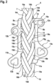
- Figure 2 shows the attachment device 8a of the plurality of attachment devices 8 of Figure 1 and, more particularly, a front side 8b of the attachment device 8a, with a section of the rope 7 of the SPIE rig 6 of Figure 1 .
- the rope 7 is a braided rope that comprises a predetermined number of strands 14 which are braided together to form the braided rope 7.
- the predetermined number is eight.
- the braided rope 7 comprises eight strands which illustratively form a first, a second, a third, and a fourth pair of strands 14a, 14b, 14c, 14d that are braided together.
- the braided rope 7 is preferably connected to the attachment device 8a, which is illustratively inserted into the plurality of strands 14 of the braided rope 7. More specifically, the attachment device 8a is inserted into the four pairs of strands 14a, 14b, 14c, 14d.
- the attachment device 8a is preferably plate-shaped, i. e. embodied as a plate-shaped element 11, which is hereinafter also referred to as the "rig plate 11", for simplicity and clarity.
- the attachment device 8a is hereinafter illustratively and representatively described with reference to the rig plate 11 only.
- the rig plate 11 is modular in that it comprises at least one braiding segment 11a, at least one first lateral fixation segment 11b, and at least one second lateral fixation segment 11c. At least one of the first and second lateral fixation segments 11b, 11c and/or the at least one braiding segment 11a may comprise metal.
- the at least one first lateral fixation segment 11b is shown on the left-hand side of the at least one braiding segment 11a and, therefore, referred to as the "left segment 11b" hereinafter, for simplicity and clarity.
- the at least one second lateral fixation segment 11c is shown on the right-hand side of the at least one braiding segment 11a and, therefore, referred to as the "right segment 11c" hereinafter, for simplicity and clarity.
- At least one of the left and right segments 11b, 11c comprises at least one anchor point for attachment of an external component, such as one of the plurality of persons 9 and/or the cargo 10 of Figure 1 .
- the left segment 11b is provided with two anchor points 12b, 13b
- the right segment 11c is provided with two anchor points 12c, 13c.
- the left segment 11b is mounted to the at least one braiding segment 11a at a first lateral attachment interface 16a
- the right segment 11c is mounted to the at least one braiding segment 11a at a second lateral attachment interface 16b.
- first lateral attachment interface 16a is illustratively arranged between the left segment 11b and the at least one braiding segment 11a, it is hereinafter referred to as the "left interface 16a", for brevity and simplicity.
- the second lateral attachment interface 16b is illustratively arranged between the right segment 11c and the at least one braiding segment 11a, it is hereinafter referred to as the "right interface 16b", for brevity and simplicity.
- the at least one braiding segment 11a is inserted and, more particularly, braided into the plurality of strands 14.
- the left and right segments 11b, 11c are mounted to the at least one braiding segment 11a for securing the plurality of strands 14 on the at least one braiding segment 11a.
- the plurality of strands 14 is braided into a plurality of associated strand eyelets 15 formed by the rig plate 11.
- the plurality of strand eyelets 15 comprises eight eyelets 15a, 15b, 15c, 15d, 15e, 15f, 15g, and 15h.
- the eyelets 15a, 15b, 15c, 15d are preferably formed, i. e. closed in circumferential direction, by attaching the left segment 11b to the at least one braiding segment 11a, and the eyelets 15e, 15f, 15g, 15h are preferably formed, i. e. closed in circumferential direction, by attaching the right segment 11b to the at least one braiding segment 11a, as described in more detail below at Figure 4 .
- Insertion of the rig plate 11 into the plurality of strands 14 of the braided rope 7 may be performed as described by way of example hereinafter: Initially, the plurality of strands 14 of the braided rope 7 is preferably loosened at a selected position of the braided rope 7, where the at least one braiding segment 11a is to be inserted into the braided rope 7. The loosening is preferably performed such that the pairs of strands 14a, 14b, 14c, 14d of the plurality of strands 14 may subsequently be manipulated separately.
- the at least one braiding segment 11a is inserted into the plurality of strands 14 at the selected position.
- the eight eyelets 15a, 15b, 15c, 15d, 15e, 15f, 15g, and 15h are laterally unclosed, i. e. in unclosed state.
- the pair of strands 14b is inserted into the eyelet 15a coming from the front side 8b toward a back side and into the eyelet 15g coming from the back side toward the front side 8b.
- the pair of strands 14c is inserted into the eyelet 15f coming from the front side 8b toward the back side and into the eyelet 15d coming from the back side toward the front side 8b.
- the pair of strands 14a is inserted into the eyelet 15e coming from the back side toward the front side 8b and into the eyelet 15c coming from the front side 8b toward the back side.
- the pair of strands 14d is inserted into the eyelet 15b coming from the back side toward the front side 8b and into the eyelet 15h coming from the front side 8b toward the back side.
- the left and right segments 11b, 11c are attached to the at least one braiding segment 11a for laterally closing the eight eyelets 15a, 15b, 15c, 15d, 15e, 15f, 15g, and 15h and, thus, fixing the pairs of strands 14a, 14b, 14c, 14d in the eight eyelets 15a, 15b, 15c, 15d, 15e, 15f, 15g, and 15h. Attachment of the left and right segments 11b, 11c to the at least one braiding segment 11a is described in more detail below at Figure 5 .
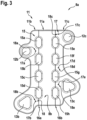
- Figure 3 shows the modular attachment device 8a of Figure 2 , which is illustratively embodied as the rig plate 11 of Figure 2 with the at least one braiding segment 11a, as well as the left and right segments 11b, 11c, which together form the plurality of eyelets 15.
- the left segment 11b comprises the anchor points 12b, 13b and is illustratively mounted to the at least one braiding segment 11a at the left interface 16a
- the right segment 11c comprises the anchor points 12c, 13c and is illustratively mounted to the at least one braiding segment 11a at the right interface 16b.
- the at least one braiding segment 11a and the left segment 11b form the eyelets 15a, 15b, 15c, 15d
- the at least one braiding segment 11a and the right segment 11c form the eyelets 15e, 15f, 15g, 15h.
- the left and right segments 11b, 11c comprise a plurality of securing member accommodations 18.
- the left segment 11b comprises two securing member accommodations 18a, 18b of the plurality of securing member accommodations 18, and the right segment 11c comprises three securing member accommodations 18c, 18d, 18e of the plurality of securing member accommodations 18.
- the securing member accommodations 18a, 18b, 18c, 18d, 18e are provided to accommodate a plurality of securing members 17. More specifically, the securing member accommodations 18a, 18b, 18c, 18d, 18e are provided to accommodate associated securing members 17a, 17b, 17c, 17d, 17e of the plurality of securing members 17, as described in more detail below at Figure 5 and Figure 6 .
- Figure 4 shows the modular attachment device 8a of Figure 2 and Figure 3 , which is illustratively embodied as the rig plate 11 of Figure 2 and Figure 3 with the at least one braiding segment 11a, as well as the left and right segments 11b, 11c, which together form the plurality of eyelets 15. More specifically, the at least one braiding segment 11a and the left segment 11b that comprises the anchor points 12b, 13b form in mounted state of the left segment 11b the eyelets 15a, 15b, 15c, 15d, and the at least one braiding segment 11a and the right segment 11c that comprises the anchor points 12c, 13c form in mounted state of the right segment 11c the eyelets 15e, 15f, 15g, 15h.
- the left and right segments 11b, 11c which are mountable to the at least one braiding segment 11a, are illustratively detached from the at least one braiding segment 11a to further illustrate the left and right interfaces 16a, 16b of Figure 2 and Figure 3 .
- the unclosed state of the eyelets 15a, 15b, 15c, 15d, 15e, 15f, 15g, 15h of the plurality of strand eyelets 15, as described in Figure 2 above, is also further illustrated.
- each one of the left and right interfaces 16a, 16b may be embodied as a tongue and groove joint.
- the tongue and groove joint is preferably provided to ensure a required tolerance compensation in lateral direction of the rig plate 11.
- each one of the left and right interfaces 16a, 16b is embodied as a tongue and groove joint.
- any other suitable form-lock and/or form-fit joints are likewise contemplated.
- the at least one braiding segment 11a may comprise at least one groove and at least one of the left and right segments 11b, 11c may comprise at least one tongue that is adapted to engage with the at least one groove upon mounting of the at least one of the left and right segments 11b, 11c to the at least one braiding segment 11a.
- the at least one braiding segment 11a comprises five grooves 20a, 20b, 20c, 20d, 20e which form a plurality of grooves 20, and the left segment 11b comprises five tongues 19a, 19b, 19c, 19d, 19e which form a plurality of tongues 19, wherein the plurality of tongues 19 is adapted to engage with the plurality of grooves 20 upon mounting of the left segment 11b to the at least one braiding segment 11a.
- the right segment 11c illustratively also comprises a plurality of tongues 21 with five tongues that are adapted to engage with a plurality of grooves 22 with five grooves provided in the at least one braiding segment 11a upon mounting of the right segment 11c to the at least one braiding segment 11a.
- the individual tongues and grooves of the plurality of tongues 21 and the plurality of grooves 22 are not separately labeled.
- the at least one braiding segment 11a is shown with the plurality of grooves 20, 22, while the left and right segments 11b, 11c are respectively provided with the plurality of tongues 19, 21.
- the at least one braiding segment 11a may instead be provided with the plurality of tongues 19, 21, while the left and right segments 11b, 11c may respectively be provided with the plurality of grooves 20, 22.
- the left segment 11b further comprises a plurality of recesses 23.
- four recesses 23a, 23b, 23c, 23d form the plurality of recesses 23.
- the recesses 23a, 23b, 23c, 23d are preferably at least approximately C-shaped.
- the at least one braiding segment 11a comprises a plurality of recesses 24.
- four recesses 24a, 24b, 24c, 24d form the plurality of recesses 24.
- the recesses 24a, 24b, 24c, 24d are also preferably at least approximately C-shaped and represent the eyelets 15a, 15b, 15c, 15d in unclosed state.
- the recesses 24a, 24b, 24c, 24d are provided for accommodation of associated pairs of strands 14a, 14b, 14c, 14d of the plurality of strands 14 of the braided rope 7 of Figure 2 , after insertion of the at least one braiding segment 11a into the plurality of strands 14 and braiding of the plurality of strands 14 around the at least one braiding segment 11a, as described above at Figure 2 .
- the pair of strands 14a would be accommodated in the recess 24c, the pair of strands 14b in the recess 24a, the pair of strands 14c in the recess 24d, and the pair of strands 14d in the recess 24b.
- the recesses 23a, 23b, 23c, 23d and the recesses 24a, 24b, 24c, 24d form respectively together the eyelets 15a, 15b, 15c, 15d in a closed state according to Figure 2 and Figure 3 . Due to the approximate C-shaped geometry of the recesses 23a, 23b, 23c, 23d and the recesses 24a, 24b, 24c, 24d, the eyelets 15a, 15b, 15c, 15d would have an at least approximately oval shape, as shown in Figure 3 .
- the right segment 11c illustratively likewise comprises a plurality of recesses that is similar to the plurality of recesses 23 and that forms together with a further plurality of recesses of the at least one braiding segment 11a, which is similar to the plurality of recesses 24, the eyelets 15e, 15f, 15g, 15h.
- this further plurality of recesses of the at least one braiding segment 11a as well as the plurality of recesses of the right segment 11c is not labelled, for simplicity and clarity of the drawing.
- the left and right segments 11b, 11c are preferably rigidly attached to the at least one braiding segment 11a. Therefore, a plurality of through-holes 25 is provided, which entirely traverse the at least one braiding segment 11a, and which preferably either completely traverse in addition the left segment 11b or the right segment 11c.
- five through-holes 25a, 25b, 25c, 25d, 25e form the plurality of through-holes 25 and entirely traverse the at least one braiding segment 11a.
- the three through-holes 25a, 25b, 25c illustratively entirely traverse the left segment 11b and merely form blind bore sections in the right segment 11c
- the two through-holes 25d, 25e illustratively entirely traverse the right segment 11c and merely form blind bore sections in the left segment 11b.
- the through-holes 25a, 25b, 25c, 25d, 25e may at least partly be embodied as threaded holes, preferably at least the blind bore sections.
- Figure 5 shows the modular attachment device 8a of Figure 2 to Figure 4 , which is illustratively embodied as the rig plate 11 of Figure 2 to Figure 4 .
- the rig plate 11 comprises the at least one braiding segment 11a and the right segment 11c, which together form the eyelets 15e, 15f, 15g, 15h of the plurality of eyelets 15.
- the right segment 11c comprises the securing member accommodations 18c, 18d, 18e of the plurality of securing member accommodations 18, which accommodate the securing members 17c, 17d, 17e of the plurality of securing members 17 according to Figure 3 .
- the right segment 11c is mounted to the at least one braiding segment 11a at the right interface 16b by means of a tongue and groove joint with the plurality of tongues 21 and the plurality of grooves 22 according to Figure 4 .
- illustration of the left segment 11b that is mountable to the at least one braiding segment 11a at the left interface 16a by means of a tongue and groove joint with the plurality of tongues (19 in Figure 4 ) and the plurality of grooves 20 according to Figure 4 is omitted to further illustrate securing of the left and right segments 11b, 11c at the at least one braiding segment 11a.
- the left segment 11b is adapted to be fixedly mounted to the at least one braiding segment 11a at the left interface 16a via associated fixation means 26a, 26c, 26d.
- the right segment 11c is adapted to be fixedly mounted to the at least one braiding segment 11a at the left interface 16b via associated fixation means 26b, 26e.
- the fixation means 26a, 26b, 26c, 26d, 26e illustratively form a plurality of fixation means 26 and may be embodied as screws, in particular self-locking screws.
- the fixation means 26b, 26e may be introduced through the right segment 11c and the at least one braiding segment 11a up to the left segment 11b. Thereby, the fixation means 26b, 26e would be accommodated in, i. e. screwed into, the through-holes 25d, 25e according to Figure 4 , i. e. their blind bore sections.
- the fixation means 26b, 26e may then be secured in the left segment 11b by means of the securing members 17a, 17b of Figure 3 .
- the securing members 17a, 17b which would be accommodated in the securing member accommodations 18a, 18b of the left segment 11b according to Figure 3 , may be embodied as grub screws.
- the fixation means 26a, 26c, 26d may be introduced through the left segment 11b and the at least one braiding segment 11a up to the right segment 11c.
- the fixation means 26a, 26c, 26d would be accommodated in, i. e. screwed into, the through-holes 25a, 25b, 25c according to Figure 4 , i. e. their blind bore sections.
- the fixation means 26a, 26c, 26d may then be secured in the right segment 11c by means of the securing members 17c, 17d, 17e of Figure 3 .
- the securing members 17c, 17d, 17e are accommodated in the securing member accommodations 18c, 18d, 18e of the right segment 11c and may also be embodied as grub screws.
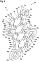
- Figure 6 shows the modular attachment device 8a of Figure 2 to Figure 5 , which is illustratively embodied as the rig plate 11 of Figure 2 to Figure 5 .
- the rig plate 11 comprises the left and right segments 11b, 11c, which are rigidly attached to each other by means of the fixation means 26a, 26b, 26c, 26d, 26e of the plurality of fixation means 26, which are respectively secured in the left or right segment 11b, 11c by means of the securing members 17a, 17b, 17c, 17d, 17e of the plurality of securing members 17.
- Figure 6 clarifies an illustrative realization, wherein the left and right segments 11b, 11c are fixedly mounted to each other by means of the fixation means 26a, 26b, 26c, 26d, 26e, while the at least one braiding segment 11a is merely hold in place between the left and right segments 11b, 11c on the fixation means 26a, 26b, 26c, 26d, 26e and by means of a form-lock or form-fit connection at the left and right interfaces 16a, 16b according to Figure 4 .
Landscapes
- Engineering & Computer Science (AREA)
- General Engineering & Computer Science (AREA)
- Mechanical Engineering (AREA)
- Health & Medical Sciences (AREA)
- General Health & Medical Sciences (AREA)
- Business, Economics & Management (AREA)
- Emergency Management (AREA)
- Braiding, Manufacturing Of Bobbin-Net Or Lace, And Manufacturing Of Nets By Knotting (AREA)
- Ropes Or Cables (AREA)
Abstract
Description
- The present invention is related to a modular attachment device for insertion into a plurality of strands of a braided rope. The present invention is further related to a Special Patrol Insertion/Extraction (SPIE) rig that comprises a braided rope with such a modular attachment device.
- In general, ropes with attachment devices are known from the state-of-the-art. In these ropes the attachment devices usually form anchor points for attachment of human or non-human cargo. By way of example, the documents
CN 112 047 228 A ,CN 205 114 816 U ,EP 3 037 133 B1 ,GB 2 340 101 BUS 1,408,940 A describe illustrative ropes with attachment devices that form anchor points. - In civil, parapublic and military missions, such ropes may embody SPIE rigs that may e. g. be used with a rotary wing aircraft, in particular a helicopter, for rapidly inserting and/or extracting persons and/or cargo from various environments, in particular environments that do not permit landing of the helicopter. Such environments may e. g. include maritime environments such as offshore as well as oil and gas platforms, and terrestrial environments such as land in vegetated areas, mountains and urban territory.
- More specifically, a SPIE rig may comprise a braided rope with a plurality of strands, into which a plurality of attachment devices is inserted. Each attachment device may be formed as a so-called "rig plate" that is inserted into and, more particularly, braided into the plurality of strands during braiding of the braided rope. Each rig plate may have one or more anchor points for attachment of human or non-human cargo.
- However, if a rig plate of a given SPIE rig is damaged and must be exchanged, the braided rope must be opened, i. e. unbraided, at least from one of its ends up to the damaged rig plate. Similarly, if e. g. an additional rig plate is to be inserted at a predetermined position in the braided rope, then the braided rope must be opened, i. e. unbraided, at least from one of its ends up to the predetermined position. In both cases, this involves time-consuming and cost-intensive manual work.
- The document
WO 2020/068603 A1 describes a method for installing an attachment device at any desired position of a given braided rope that comprises a plurality of strands. According to this method, the given braided rope is opened at a desired position, i. e. the plurality of strands is loosened and separated along the midline of the braided rope at the desired position to form a hole into which a sleeve is inserted. The sleeve is then secured and hold in position in the braided rope by means of an outer case which is mounted to the braided rope at the desired position. However, the sleeve is merely inserted into the plurality of strands, but not braided thereinto. - It is an object of the present invention to provide a new attachment device for insertion into a plurality of strands of a braided rope, which may easily and securely be braided into the plurality of strands and form a high strength, robust and low-wear load introduction point into the braided rope.
- This object is solved by a modular attachment device that comprises the features of
claim 1. More specifically, according to the present invention a modular attachment device for insertion into a plurality of strands of a braided rope is provided. The modular attachment device comprises at least one braiding segment that is braidable into the plurality of strands, at least one first lateral fixation segment that is mountable to the at least one braiding segment at a first lateral attachment interface, and at least one second lateral fixation segment that is mountable to the at least one braiding segment at a second lateral attachment interface. The first and second lateral fixation segments are mountable to the at least one braiding segment for securing the plurality of strands on the at least one braiding segment. At least one of the first and second lateral fixation segments comprises at least one anchor point for attachment of an external component. - Advantageously, the inventive attachment device is modular in that it comprises at least three separate base components: the at least one braiding segment, the at least one first lateral fixation segment, and the at least one second lateral fixation segment. These separate base components are preferably attached to each other at an associated position in the braided rope to enable use of the respective anchor points at the associated position. Preferably, the first and second lateral fixation segments are respectively attached to each other by means of suitable securing members.
- The separate base components may comprise different materials which may be selected in order to optimize an underlying functionality and/or specific characteristics. For instance, the at least one braiding segment may be optimized with respect to its weight, e. g. to be as lightweight as possible and/or to enable high strength at respective braiding recesses. Accordingly, the at least one braiding segment may be made of fiber reinforced material. The at least one first and second lateral fixation segments, in turn, may be optimized with respect to damage tolerance and/or to exhibit high tolerance for lateral loads. By way of example, the at least one first and second lateral fixation segments may comprise metal.
- More specifically, due to their modularity the modular attachment device may be inserted at any desired position into a previously braided rope without unbraiding the entire rope or a part of the rope from one of its ends up to the desired position. Consequently, the braided rope may initially be braided completely and after braiding the modular attachment device can be inserted at the desired position. Likewise, a given modular attachment device may be removed from an associated position in a braided rope without unbraiding the entire rope or a part of the rope from one of its ends up to the associated position. Thus, time-consuming and cost-intensive manual work for unbraiding and re-braiding may be avoided.
- As a result, respective modular attachment devices may be added to a given braided rope or replaced in the given braided rope at any time with negligible effort. Furthermore, the respective modular attachment devices may be moved from respectively associated positions to other desired positions in the braided rope with negligible effort.
- Advantageously, the at least one braiding segment may easily be replaced, in particular with comparatively low costs. For instance, the at least one braiding segment may be replaced if it is damaged or it may simply be replaced with a newly designed braiding segment that e. g. comprises one or more additional braiding recesses.
- Similarly, one or both lateral fixation segments may easily be replaced, in particular with comparatively low costs. For instance, a lateral fixation segment may be replaced if it is damaged or it may simply be replaced with a newly designed lateral fixation segment that e. g. comprises one or more additional anchor points and/or a modified outer contour.
- Moreover, the inventive attachment device advantageously exhibits a stable design. More specifically, tension loads are preferably introduced into the securing members which attach the first and second lateral fixation segments to each other, while moments are e. g. introduced into a tongue and groove joint that connects the first and second lateral fixation segments to an associated braiding segment. The tongue and groove joint may be replaced by any suitable form-lock or form-fit connection.
- According to one aspect, the at least one braiding segment comprises a plurality of recesses for accommodation of associated pairs of strands of the plurality of strands.
- According to one aspect, the recesses of the plurality of recesses are at least approximately C-shaped.
- According to one aspect, the at least one first lateral fixation segment and/or the at least one second lateral fixation segment comprises a plurality of recesses that are configured to form with the plurality of recesses of the at least one braiding segment a plurality of strand eyelets, after mounting of the at least one first lateral fixation segment and/or the at least one second lateral fixation segment to the at least one braiding segment.
- According to one aspect, the recesses of the plurality of recesses of the at least one first lateral fixation segment and/or the at least one second lateral fixation segment are at least approximately C-shaped.
- According to one aspect, at least one of the first and second lateral attachment interfaces is embodied as a tongue and groove joint.
- According to one aspect, the at least one braiding segment comprises at least one groove, wherein at least one of the first and second lateral fixation segments comprises at least one tongue that is adapted to engage with the at least one groove upon mounting of the at least one of the first and second lateral fixation segments to the at least one braiding segment.
- According to one aspect, at least one of the first and second lateral fixation segments comprises at least one groove, wherein the at least one braiding segment comprises at least one tongue that is adapted to engage with the at least one groove upon mounting of the at least one of the first and second lateral fixation segments to the at least one braiding segment.
- According to one aspect, the at least one first lateral fixation segment is adapted to be fixedly mounted to the at least one braiding segment at the first lateral attachment interface via associated fixation means.
- According to one aspect, the at least one second lateral fixation segment is adapted to be fixedly mounted to the at least one braiding segment at the second lateral attachment interface via associated fixation means.
- According to one aspect, the associated fixation means are screws, in particular self-locking screws.
- According to one aspect, at least one of the first and second lateral fixation segments and/or the at least one braiding segment comprises at least one securing member accommodation for accommodating a securing member that is adapted to secure one of the associated fixation means after mounting of the at least one first lateral fixation segment and/or the at least one second lateral fixation segment to the at least one braiding segment.
- According to one aspect, the securing member is a grub screw.
- According to one aspect, the modular attachment device is embodied as a rig plate, wherein at least one of the first and second lateral fixation segments and/or the at least one braiding segment comprises metal.
- The present invention further relates to a SPIE rig with a braided rope and at least one modular attachment device as described above.
- Advantageously, any braided rope may easily be transformed into a SPIE rig due to the modularity of the inventive attachment device. The SPIE rig may easily be adapted to respective customer needs, e. g. with respect to underlying operation platforms.
- More specifically, such a SPIE rig may be made of an uninterrupted braided rope with no splices and no sewing, and would be multi-redundant in-depth inspectable, in particular using non-destructive testing procedures. In such a SPIE rig the modularity of the inventive attachment device allows full inspection and a full, simple, economic, reliable exchange of all constituent components. Full inspection advantageously includes inspection at respective interfaces between the braided rope and the inventive attachment device.
- Furthermore, in such a SPIE rig the main part of the inventive attachment device, i. e. essentially the whole braiding segment, is covered by the braided rope. Therefore, an underlying rope-characteristic regarding handling persists. Moreover, the load transfer from the attachment device to the braided rope works via a combination of friction and form-fit, as the braiding segment is braided into the braided rope. Due to the form-fit design, the attachment cannot release from the braided rope in case of overloading. Finally, as the braided rope may be provided with an attachment device that can be integrated into an already braided rope, the attachment device may have any almost freely selectable length and capacity and it can be inserted into the braided rope at any position.
- Preferred embodiments of the invention are outlined by way of example in the following description with reference to the attached drawings. In these attached drawings, identical or identically functioning components and elements are labeled with identical reference numbers and characters and are, consequently, only described once in the following description.
-
Figure 1 shows a perspective view of a rotary wing aircraft with a SPIE rig according to one aspect, -
Figure 2 shows a front view of an enlarged detail of the SPIE rig ofFigure 1 with a modular attachment device according to an embodiment, -
Figure 3 shows a front view of the modular attachment device ofFigure 2 with a braiding segment and first and second lateral fixation segments, -
Figure 4 shows an exploded perspective view of the modular attachment device ofFigure 3 , -
Figure 5 shows a perspective view of the braiding segment and the second lateral fixation segment ofFigure 3 andFigure 4 , and -
Figure 6 shows a perspective view of the first and second lateral fixation segments ofFigure 3 andFigure 4 . -
Figure 1 shows arotary wing aircraft 1 that illustratively comprises afuselage 2 with abottom shell 2c. By way of example, thefuselage 2 forms acabin 2b for passengers and/or cargo and atail boom 2a is mounted to thefuselage 2. - The
rotary wing aircraft 1 illustratively further comprises at least onemain rotor 1a configured to provide lift and forward or backward thrust during operation, and at least one counter-torque device 3 configured to provide counter-torque during operation, i. e. to counter the torque created by rotation of the at least onemain rotor 1a for purposes of balancing therotary wing aircraft 1 in terms of yaw. - The at least one counter-torque device 3 is illustratively provided at an aft section of the
tail boom 2a, which preferably further comprises afin 4. However, it should be noted that the at least one counter-torque device 3, as well as thefin 4 provided at the aft section of thetail boom 2a, are merely described for illustrating one possible realization of therotary wing aircraft 1. - According to one aspect, the
rotary wing aircraft 1 is provided with aSPIE rig 6. By way of example, theSPIE rig 6 is attached to an associatedattachment 5 provided at thebottom shell 2c. Theattachment 5 is illustratively embodied as an attachment ring which may e. g. be connected to a cable that is coupled to a winch. - More specifically, the
SPIE rig 6 preferably comprises arope 7 with arope interface 7a, such as an eyelet, which is illustratively attached to theattachment 5, e. g. by means of a snap hook respectively carabiner. Therope 7 is preferably provided with at least oneattachment device 8a and, illustratively, with a plurality of attachment devices 8. The plurality of attachment devices 8 is preferably provided to enable attachment of external components such as human and/or non-human cargo thereto and, thus, to therope 7. By way of example, a plurality of persons 9 and somecargo 10 are attached to the plurality of attachment devices 8. TheSPIE rig 6 and/or its constituent components are further described below with reference toFigure 2 to Figure 6 . - Illustratively, the
rotary wing aircraft 1 with theSPIE rig 6 is shown in operation. In this illustrative operation, theSPIE rig 6 may e. g. be used for inserting or extracting the persons 9 and/or thecargo 10 into/from a respective environment. - By way of example, the
rotary wing aircraft 1 is embodied as a helicopter. However, use of theSPIE rig 6 is not limited to use with a helicopter. Instead, theSPIE rig 6 may be used with other rotary wing aircrafts, such as e. g. tiltrotor aircrafts, compound helicopters, multicopters and so on. More generally, theSPIE rig 6 may be used completely independent of therotary wing aircraft 1 for any possible rig and tackle applications, such as e. g. in sailing, climbing and so on. -
Figure 2 shows theattachment device 8a of the plurality of attachment devices 8 ofFigure 1 and, more particularly, afront side 8b of theattachment device 8a, with a section of therope 7 of theSPIE rig 6 ofFigure 1 . According to the present invention, therope 7 is a braided rope that comprises a predetermined number ofstrands 14 which are braided together to form thebraided rope 7. By way of example, the predetermined number is eight. Accordingly, thebraided rope 7 comprises eight strands which illustratively form a first, a second, a third, and a fourth pair ofstrands - The
braided rope 7 is preferably connected to theattachment device 8a, which is illustratively inserted into the plurality ofstrands 14 of thebraided rope 7. More specifically, theattachment device 8a is inserted into the four pairs ofstrands - The
attachment device 8a is preferably plate-shaped, i. e. embodied as a plate-shapedelement 11, which is hereinafter also referred to as the "rig plate 11", for simplicity and clarity. By way of example, and not for restricting the present invention accordingly, theattachment device 8a is hereinafter illustratively and representatively described with reference to therig plate 11 only. - According to the present invention, the
rig plate 11 is modular in that it comprises at least onebraiding segment 11a, at least one firstlateral fixation segment 11b, and at least one secondlateral fixation segment 11c. At least one of the first and secondlateral fixation segments braiding segment 11a may comprise metal. - By way of example, the at least one first
lateral fixation segment 11b is shown on the left-hand side of the at least onebraiding segment 11a and, therefore, referred to as the "leftsegment 11b" hereinafter, for simplicity and clarity. The at least one secondlateral fixation segment 11c is shown on the right-hand side of the at least onebraiding segment 11a and, therefore, referred to as the "right segment 11c" hereinafter, for simplicity and clarity. - At least one of the left and
right segments cargo 10 ofFigure 1 . Illustratively, theleft segment 11b is provided with twoanchor points right segment 11c is provided with twoanchor points - The
left segment 11b is mounted to the at least onebraiding segment 11a at a firstlateral attachment interface 16a, and theright segment 11c is mounted to the at least onebraiding segment 11a at a secondlateral attachment interface 16b. As the firstlateral attachment interface 16a is illustratively arranged between theleft segment 11b and the at least onebraiding segment 11a, it is hereinafter referred to as the "leftinterface 16a", for brevity and simplicity. Similarly, as the secondlateral attachment interface 16b is illustratively arranged between theright segment 11c and the at least onebraiding segment 11a, it is hereinafter referred to as the "right interface 16b", for brevity and simplicity. - The at least one
braiding segment 11a is inserted and, more particularly, braided into the plurality ofstrands 14. The left andright segments braiding segment 11a for securing the plurality ofstrands 14 on the at least onebraiding segment 11a. - Illustratively, the plurality of
strands 14 is braided into a plurality of associated strand eyelets 15 formed by therig plate 11. By way of example, the plurality of strand eyelets 15 comprises eighteyelets eyelets left segment 11b to the at least onebraiding segment 11a, and theeyelets right segment 11b to the at least onebraiding segment 11a, as described in more detail below atFigure 4 . - Insertion of the
rig plate 11 into the plurality ofstrands 14 of thebraided rope 7 may be performed as described by way of example hereinafter:
Initially, the plurality ofstrands 14 of thebraided rope 7 is preferably loosened at a selected position of thebraided rope 7, where the at least onebraiding segment 11a is to be inserted into thebraided rope 7. The loosening is preferably performed such that the pairs ofstrands strands 14 may subsequently be manipulated separately. - Then, the at least one
braiding segment 11a is inserted into the plurality ofstrands 14 at the selected position. As the left andright segments braiding segment 11a, the eighteyelets - Subsequently, the pair of
strands 14b is inserted into theeyelet 15a coming from thefront side 8b toward a back side and into theeyelet 15g coming from the back side toward thefront side 8b. Then, the pair ofstrands 14c is inserted into theeyelet 15f coming from thefront side 8b toward the back side and into theeyelet 15d coming from the back side toward thefront side 8b. Furthermore, the pair ofstrands 14a is inserted into theeyelet 15e coming from the back side toward thefront side 8b and into theeyelet 15c coming from thefront side 8b toward the back side. Moreover, the pair ofstrands 14d is inserted into theeyelet 15b coming from the back side toward thefront side 8b and into theeyelet 15h coming from thefront side 8b toward the back side. - Finally, the left and
right segments braiding segment 11a for laterally closing the eighteyelets strands eyelets right segments braiding segment 11a is described in more detail below atFigure 5 . -
Figure 3 shows themodular attachment device 8a ofFigure 2 , which is illustratively embodied as therig plate 11 ofFigure 2 with the at least onebraiding segment 11a, as well as the left andright segments eyelets 15. Theleft segment 11b comprises the anchor points 12b, 13b and is illustratively mounted to the at least onebraiding segment 11a at theleft interface 16a, and theright segment 11c comprises the anchor points 12c, 13c and is illustratively mounted to the at least onebraiding segment 11a at theright interface 16b. Furthermore, the at least onebraiding segment 11a and theleft segment 11b form theeyelets braiding segment 11a and theright segment 11c form theeyelets - Illustratively, the left and
right segments member accommodations 18. By way of example, theleft segment 11b comprises two securingmember accommodations member accommodations 18, and theright segment 11c comprises three securingmember accommodations member accommodations 18. - The securing
member accommodations members 17. More specifically, the securingmember accommodations members members 17, as described in more detail below atFigure 5 andFigure 6 . -
Figure 4 shows themodular attachment device 8a ofFigure 2 andFigure 3 , which is illustratively embodied as therig plate 11 ofFigure 2 andFigure 3 with the at least onebraiding segment 11a, as well as the left andright segments eyelets 15. More specifically, the at least onebraiding segment 11a and theleft segment 11b that comprises the anchor points 12b, 13b form in mounted state of theleft segment 11b theeyelets braiding segment 11a and theright segment 11c that comprises the anchor points 12c, 13c form in mounted state of theright segment 11c theeyelets - However, in contrast to
Figure 2 andFigure 3 the left andright segments braiding segment 11a, are illustratively detached from the at least onebraiding segment 11a to further illustrate the left andright interfaces Figure 2 andFigure 3 . Moreover, the unclosed state of theeyelets Figure 2 above, is also further illustrated. - More specifically, at least one of the left and
right interfaces rig plate 11. Preferably, each one of the left andright interfaces - For instance, the at least one
braiding segment 11a may comprise at least one groove and at least one of the left andright segments right segments braiding segment 11a. Illustratively, the at least onebraiding segment 11a comprises fivegrooves grooves 20, and theleft segment 11b comprises fivetongues tongues 19, wherein the plurality oftongues 19 is adapted to engage with the plurality ofgrooves 20 upon mounting of theleft segment 11b to the at least onebraiding segment 11a. - Similarly, the
right segment 11c illustratively also comprises a plurality oftongues 21 with five tongues that are adapted to engage with a plurality ofgrooves 22 with five grooves provided in the at least onebraiding segment 11a upon mounting of theright segment 11c to the at least onebraiding segment 11a. However, for simplicity and clarity of the drawing the individual tongues and grooves of the plurality oftongues 21 and the plurality ofgrooves 22 are not separately labeled. - It should be noted that the at least one
braiding segment 11a is shown with the plurality ofgrooves right segments tongues braiding segment 11a may instead be provided with the plurality oftongues right segments grooves - Illustratively, the
left segment 11b further comprises a plurality ofrecesses 23. By way of example, fourrecesses recesses 23. Therecesses - Similarly, the at least one
braiding segment 11a comprises a plurality ofrecesses 24. By way of example, fourrecesses recesses 24. Therecesses eyelets - More particularly, the
recesses strands strands 14 of thebraided rope 7 ofFigure 2 , after insertion of the at least onebraiding segment 11a into the plurality ofstrands 14 and braiding of the plurality ofstrands 14 around the at least onebraiding segment 11a, as described above atFigure 2 . According to the example ofFigure 2 , the pair ofstrands 14a would be accommodated in the recess 24c, the pair ofstrands 14b in therecess 24a, the pair ofstrands 14c in therecess 24d, and the pair ofstrands 14d in therecess 24b. - Upon mounting of the
left segment 11b to the at least onebraiding segment 11a, therecesses recesses eyelets Figure 2 andFigure 3 . Due to the approximate C-shaped geometry of therecesses recesses eyelets Figure 3 . - It should be noted that the
right segment 11c illustratively likewise comprises a plurality of recesses that is similar to the plurality ofrecesses 23 and that forms together with a further plurality of recesses of the at least onebraiding segment 11a, which is similar to the plurality ofrecesses 24, theeyelets braiding segment 11a as well as the plurality of recesses of theright segment 11c is not labelled, for simplicity and clarity of the drawing. - As described above, the left and
right segments braiding segment 11a. Therefore, a plurality of through-holes 25 is provided, which entirely traverse the at least onebraiding segment 11a, and which preferably either completely traverse in addition theleft segment 11b or theright segment 11c. - By way of example, five through-
holes holes 25 and entirely traverse the at least onebraiding segment 11a. Furthermore, the three through-holes left segment 11b and merely form blind bore sections in theright segment 11c, and the two through-holes right segment 11c and merely form blind bore sections in theleft segment 11b. The through-holes -
Figure 5 shows themodular attachment device 8a ofFigure 2 to Figure 4 , which is illustratively embodied as therig plate 11 ofFigure 2 to Figure 4 . By way of example, therig plate 11 comprises the at least onebraiding segment 11a and theright segment 11c, which together form theeyelets eyelets 15. Theright segment 11c comprises the securingmember accommodations member accommodations 18, which accommodate the securingmembers members 17 according toFigure 3 . Furthermore, theright segment 11c is mounted to the at least onebraiding segment 11a at theright interface 16b by means of a tongue and groove joint with the plurality oftongues 21 and the plurality ofgrooves 22 according toFigure 4 . However, in contrast toFigure 2 andFigure 3 illustration of theleft segment 11b that is mountable to the at least onebraiding segment 11a at theleft interface 16a by means of a tongue and groove joint with the plurality of tongues (19 inFigure 4 ) and the plurality ofgrooves 20 according toFigure 4 is omitted to further illustrate securing of the left andright segments braiding segment 11a. - More specifically, the
left segment 11b is adapted to be fixedly mounted to the at least onebraiding segment 11a at theleft interface 16a via associated fixation means 26a, 26c, 26d. Theright segment 11c, in turn, is adapted to be fixedly mounted to the at least onebraiding segment 11a at theleft interface 16b via associated fixation means 26b, 26e. The fixation means 26a, 26b, 26c, 26d, 26e illustratively form a plurality of fixation means 26 and may be embodied as screws, in particular self-locking screws. - By way of example, the fixation means 26b, 26e may be introduced through the
right segment 11c and the at least onebraiding segment 11a up to theleft segment 11b. Thereby, the fixation means 26b, 26e would be accommodated in, i. e. screwed into, the through-holes Figure 4 , i. e. their blind bore sections. The fixation means 26b, 26e may then be secured in theleft segment 11b by means of the securingmembers Figure 3 . By way of example, the securingmembers member accommodations left segment 11b according toFigure 3 , may be embodied as grub screws. - Similarly, the fixation means 26a, 26c, 26d may be introduced through the
left segment 11b and the at least onebraiding segment 11a up to theright segment 11c. Thereby, the fixation means 26a, 26c, 26d would be accommodated in, i. e. screwed into, the through-holes Figure 4 , i. e. their blind bore sections. The fixation means 26a, 26c, 26d may then be secured in theright segment 11c by means of the securingmembers Figure 3 . By way of example, the securingmembers member accommodations right segment 11c and may also be embodied as grub screws. -
Figure 6 shows themodular attachment device 8a ofFigure 2 to Figure 5 , which is illustratively embodied as therig plate 11 ofFigure 2 to Figure 5 . By way of example, therig plate 11 comprises the left andright segments right segment members members 17. - However, in contrast to
Figure 2 to Figure 5 illustration of the at least onebraiding segment 11a is omitted. Thus,Figure 6 clarifies an illustrative realization, wherein the left andright segments braiding segment 11a is merely hold in place between the left andright segments right interfaces Figure 4 . -
- 1
- rotary wing aircraft
- 1a
- main rotor
- 2
- fuselage
- 2a
- tail boom
- 2b
- cabin
- 2c
- bottom shell
- 3
- counter-torque device
- 4
- fin
- 5
- rope attachment
- 6
- Special Patrol Insertion/Extraction rig
- 7
- braided rope
- 7a
- rope interface
- 8
- plurality of attachment devices
- 8a
- attachment device
- 8b
- attachment device front side
- 9
- persons
- 10
- cargo
- 11
- rig plate
- 11a
- center braiding segment
- 11b, 11c
- lateral fixation segments
- 12b, 12c
- anchor points
- 13b, 13c
- anchor points
- 14
- strands
- 14a, 14b, 14c, 14d
- pairs of strands
- 15
- strand eyelets
- 15a, 15b, 15c, 15d, 15e, 15f, 15g, 15h
- strand eyelet
- 16a,
- 16b lateral attachment interfaces
- 17
- securing members
- 17a, 17b, 17c, 17d, 17e
- securing member
- 18
- securing members accommodations
- 18a, 18b, 18c, 18d, 18e
- securing member accommodation
- 19
- plurality of tongues
- 19a, 19b, 19c, 19d, 19e
- tongue
- 20
- plurality of grooves
- 20a, 20b, 20c, 20d, 20e
- groove
- 21
- plurality of tongues
- 22
- plurality of grooves
- 23
- plurality of C-shaped recesses
- 23a, 23b, 23c, 23d
- C-shaped recess
- 24
- plurality of C-shaped recesses
- 24a, 24b, 24c, 24d
- C-shaped recess
- 25
- plurality of through-holes
- 25a, 25b, 25c
- through-holes
- 26
- plurality of fixation means
- 26a, 26b, 26c, 26d, 26e
- fixation means
Claims (15)
- A modular attachment device (11) for insertion into a plurality of strands (14) of a braided rope (7), comprising:at least one braiding segment (11a) that is braidable into the plurality of strands (14);at least one first lateral fixation segment (11b) that is mountable to the at least one braiding segment (11a) at a first lateral attachment interface (16a); andat least one second lateral fixation segment (11c) that is mountable to the at least one braiding segment (11a) at a second lateral attachment interface (16b),wherein at least one of the first and second lateral fixation segments (11b, 11c) comprises at least one anchor point (12b, 13b; 12c, 13c) for attachment of an external component (9, 10), and wherein the first and second lateral fixation segments (11b, 11c) are mountable to the at least one braiding segment (11a) for securing the plurality of strands (14) on the at least one braiding segment (11a).
- The modular attachment device (11) of claim 1, wherein the at least one braiding segment (11a) comprises a plurality of recesses (24) for accommodation of associated pairs of strands (14a, 14b, 14c, 14d) of the plurality of strands (14).
- The modular attachment device (11) of claim 2, wherein the recesses (24a, 24b, 24c, 24d) of the plurality of recesses (24) are at least approximately C-shaped.
- The modular attachment device (11) of claim 2 or 3, wherein the at least one first lateral fixation segment (11b) and/or the at least one second lateral fixation segment (11c) comprises a plurality of recesses (23) that are configured to form with the plurality of recesses (24) of the at least one braiding segment (11a) a plurality of strand eyelets (15), after mounting of the at least one first lateral fixation segment (11b) and/or the at least one second lateral fixation segment (11c) to the at least one braiding segment (11a).
- The modular attachment device (11) of claim 4, wherein the recesses (23a, 23b, 23c, 23d) of the plurality of recesses (23) of the at least one first lateral fixation segment (11b) and/or the at least one second lateral fixation segment (11c) are at least approximately C-shaped.
- The modular attachment device (11) of any one of the preceding claims, wherein at least one of the first and second lateral attachment interfaces (16a, 16b) is embodied as a tongue and groove joint.
- The modular attachment device (11) of any one of the preceding claims, wherein the at least one braiding segment (11a) comprises at least one groove (20a, 20b, 20c, 20d, 20e), and wherein at least one of the first and second lateral fixation segments (11b, 11c) comprises at least one tongue (19a, 19b, 19c, 19d, 19e) that is adapted to engage with the at least one groove (20a, 20b, 20c, 20d, 20e) upon mounting of the at least one of the first and second lateral fixation segments (11b, 11c) to the at least one braiding segment (11a).
- The modular attachment device (11) of any one of the preceding claims, wherein at least one of the first and second lateral fixation segments (11b, 11c) comprises at least one groove, and wherein the at least one braiding segment (11a) comprises at least one tongue that is adapted to engage with the at least one groove upon mounting of the at least one of the first and second lateral fixation segments (11b, 11c) to the at least one braiding segment (11a).
- The modular attachment device (11) of any one of the preceding claims, wherein the at least one first lateral fixation segment (11b) is adapted to be fixedly mounted to the at least one braiding segment (11a) at the first lateral attachment interface (16a) via associated fixation means (26a, 26c, 26d).
- The modular attachment device (11) of any one of the preceding claims, wherein the at least one second lateral fixation segment (11c) is adapted to be fixedly mounted to the at least one braiding segment (11a) at the second lateral attachment interface (16b) via associated fixation means (26b, 26e).
- The modular attachment device (11) of claim 9 or 10, wherein the associated fixation means (26a, 26b, 26c, 26d, 26e) are screws, in particular self-locking screws.
- The modular attachment device (11) of any one of claims 9 to 11, wherein at least one of the first and second lateral fixation segments (11b, 11c) and/or the at least one braiding segment (11a) comprises at least one securing member accommodation (18a, 18b, 18c, 18d, 18e) for accommodating a securing member (17a, 17b, 17c, 17d, 17e) that is adapted to secure one of the associated fixation means (26a, 26b, 26c, 26d, 26e) after mounting of the at least one first lateral fixation segment (11b) and/or the at least one second lateral fixation segment (11c) to the at least one braiding segment (11a).
- The modular attachment device (11) of claim 12, wherein the securing member (17a, 17b, 17c, 17d, 17e) is a grub screw.
- The modular attachment device (11) of any one of the preceding claims, which is embodied as a rig plate, wherein at least one of the first and second lateral fixation segments (11b, 11c) and/or the at least one braiding segment (11a) comprises metal.
- A Special Patrol Insertion/Extraction rig (6) with a braided rope (7) and at least one modular attachment device (11) according to any one of the preceding claims.
Priority Applications (3)
| Application Number | Priority Date | Filing Date | Title |
|---|---|---|---|
| EP21400017.6A EP4124775B1 (en) | 2021-07-26 | 2021-07-26 | A modular attachment device for insertion into a plurality of strands of a braided rope |
| CA3167914A CA3167914C (en) | 2021-07-26 | 2022-03-31 | A modular attachment device for insertion into a plurality of strands of a braided rope |
| US17/722,516 US12209634B2 (en) | 2021-07-26 | 2022-04-18 | Modular attachment device for insertion into a plurality of strands of a braided rope |
Applications Claiming Priority (1)
| Application Number | Priority Date | Filing Date | Title |
|---|---|---|---|
| EP21400017.6A EP4124775B1 (en) | 2021-07-26 | 2021-07-26 | A modular attachment device for insertion into a plurality of strands of a braided rope |
Publications (2)
| Publication Number | Publication Date |
|---|---|
| EP4124775A1 true EP4124775A1 (en) | 2023-02-01 |
| EP4124775B1 EP4124775B1 (en) | 2023-09-06 |
Family
ID=78032381
Family Applications (1)
| Application Number | Title | Priority Date | Filing Date |
|---|---|---|---|
| EP21400017.6A Active EP4124775B1 (en) | 2021-07-26 | 2021-07-26 | A modular attachment device for insertion into a plurality of strands of a braided rope |
Country Status (3)
| Country | Link |
|---|---|
| US (1) | US12209634B2 (en) |
| EP (1) | EP4124775B1 (en) |
| CA (1) | CA3167914C (en) |
Families Citing this family (2)
| Publication number | Priority date | Publication date | Assignee | Title |
|---|---|---|---|---|
| EP4124775B1 (en) * | 2021-07-26 | 2023-09-06 | AIRBUS HELICOPTERS DEUTSCHLAND GmbH | A modular attachment device for insertion into a plurality of strands of a braided rope |
| KR102884762B1 (en) * | 2023-07-26 | 2025-11-11 | 주식회사 지디아이앤디 | Loop string fixing device and method for providing loop string fixing device |
Citations (7)
| Publication number | Priority date | Publication date | Assignee | Title |
|---|---|---|---|---|
| US1408940A (en) | 1921-05-02 | 1922-03-07 | Walter C Harley | Adjustable rope fastener |
| GB2340101B (en) | 1998-07-29 | 2002-02-13 | Allan Brocklebank | Helicopter rescue system |
| US20110173780A1 (en) * | 2006-12-05 | 2011-07-21 | Conterra, Inc. | Systems and methods for controlling rope |
| CN205114816U (en) | 2015-09-30 | 2016-03-30 | 无锡市爱德森机械有限公司 | Compound rigging that promotes of sewage pump |
| EP3037133B1 (en) | 2014-12-23 | 2018-06-27 | Iveco Magirus Ag | Lanyard assembly for lifting a rescue apparatus |
| WO2020068603A1 (en) | 2018-09-24 | 2020-04-02 | Axxis Geo Solutions AS | Method and apparatus for providing connection points along a rope or other braided or twisted line |
| CN112047228A (en) | 2020-08-05 | 2020-12-08 | 山东鲁普科技有限公司 | Multi-eye braided rope |
Family Cites Families (15)
| Publication number | Priority date | Publication date | Assignee | Title |
|---|---|---|---|---|
| US1920970A (en) * | 1930-04-28 | 1933-08-08 | John M Chevalier | Guy-line clamp |
| US2193236A (en) * | 1937-11-16 | 1940-03-12 | William A Meighan | Rope fitting |
| DE69514257T2 (en) * | 1994-02-21 | 2000-08-31 | Collux Ab, Falsterbo | Implant for the treatment of fractures of the femur |
| US20040034972A1 (en) * | 2002-08-26 | 2004-02-26 | Brown Jason Aaron | Rope-securing device |
| US6966520B2 (en) * | 2003-09-18 | 2005-11-22 | Sherman Keith E | Line tensioning and coupling apparatus |
| WO2010025405A1 (en) * | 2008-08-29 | 2010-03-04 | Life Spine, Inc. | Single-sided dynamic spine plates |
| US8091866B2 (en) * | 2009-04-09 | 2012-01-10 | Christopher L White | Wire pull assembly |
| FR3082417B1 (en) * | 2018-06-19 | 2021-06-25 | Arnaud Destainville | MODULAR BONE PLATE MODULE AGENCY TO RECEIVE AN ANCHORING DEVICE, MODULAR BONE PLATE THUS CONSTITUTED AND SYSTEM INCLUDING THE PLATE AND ANCHORING DEVICE |
| FR3082416B1 (en) * | 2018-06-19 | 2021-04-23 | Arnaud Destainville | MODULE AND TERMINAL MODULE FOR MODULAR BONE PLATE, MODULAR BONE PLATE THUS CONSTITUTED AND SYSTEM INCLUDING THE PLATE |
| US20220409247A1 (en) * | 2019-07-19 | 2022-12-29 | Tyber Medical Llc | Fixing Plate with Locking Mechanism Assembly |
| US12137946B2 (en) * | 2020-03-17 | 2024-11-12 | Aegis Spine, Inc. | Spinal plate |
| US11357555B2 (en) * | 2020-11-25 | 2022-06-14 | Yu-Ju Lin | Bone fastening device having plates and screws |
| EP4124775B1 (en) * | 2021-07-26 | 2023-09-06 | AIRBUS HELICOPTERS DEUTSCHLAND GmbH | A modular attachment device for insertion into a plurality of strands of a braided rope |
| US12038067B2 (en) * | 2021-10-19 | 2024-07-16 | Sheridon L. Petersen | Rope coupling apparatus |
| USD1004776S1 (en) * | 2022-01-20 | 2023-11-14 | Mirus Llc | Cervical plate |
-
2021
- 2021-07-26 EP EP21400017.6A patent/EP4124775B1/en active Active
-
2022
- 2022-03-31 CA CA3167914A patent/CA3167914C/en active Active
- 2022-04-18 US US17/722,516 patent/US12209634B2/en active Active
Patent Citations (7)
| Publication number | Priority date | Publication date | Assignee | Title |
|---|---|---|---|---|
| US1408940A (en) | 1921-05-02 | 1922-03-07 | Walter C Harley | Adjustable rope fastener |
| GB2340101B (en) | 1998-07-29 | 2002-02-13 | Allan Brocklebank | Helicopter rescue system |
| US20110173780A1 (en) * | 2006-12-05 | 2011-07-21 | Conterra, Inc. | Systems and methods for controlling rope |
| EP3037133B1 (en) | 2014-12-23 | 2018-06-27 | Iveco Magirus Ag | Lanyard assembly for lifting a rescue apparatus |
| CN205114816U (en) | 2015-09-30 | 2016-03-30 | 无锡市爱德森机械有限公司 | Compound rigging that promotes of sewage pump |
| WO2020068603A1 (en) | 2018-09-24 | 2020-04-02 | Axxis Geo Solutions AS | Method and apparatus for providing connection points along a rope or other braided or twisted line |
| CN112047228A (en) | 2020-08-05 | 2020-12-08 | 山东鲁普科技有限公司 | Multi-eye braided rope |
Also Published As
| Publication number | Publication date |
|---|---|
| EP4124775B1 (en) | 2023-09-06 |
| CA3167914A1 (en) | 2023-01-26 |
| US12209634B2 (en) | 2025-01-28 |
| CA3167914C (en) | 2023-10-31 |
| US20230026372A1 (en) | 2023-01-26 |
Similar Documents
| Publication | Publication Date | Title |
|---|---|---|
| CA3167914C (en) | A modular attachment device for insertion into a plurality of strands of a braided rope | |
| EP3109159B1 (en) | A rope suspension device with at least one rope suspension module | |
| CN108688791B (en) | Movable wing for weight and balance management | |
| US8851425B2 (en) | Removable support for optional external equipment on an aircraft, and an aircraft provided with such a support | |
| CN105712178B (en) | Guy rope assembly for lifting rescue equipment | |
| AU2018288009A1 (en) | Aerial vehicle tether | |
| EP3225537B1 (en) | A helicopter with a fuselage and a composite tail boom | |
| US12497834B2 (en) | Rope ladder with two braided ropes | |
| EP4197909B1 (en) | A human and/or non-human cargo attachment device for use with a rotorcraft | |
| EP3556655B1 (en) | An apparatus for carrying cargo with an aircraft | |
| US11155355B2 (en) | Mounting assembly | |
| DE102004009020B4 (en) | Intercostal for airplanes | |
| EP4520654A1 (en) | An apparatus for connection to an anchor track or an anchor point in an aircraft | |
| KR102827456B1 (en) | Impact shackle | |
| EP4717596A1 (en) | A swivel device for connecting human and/or non-human cargo to a rotorcraft | |
| EP4282754B1 (en) | An attachment assembly for attachment of a tail boom to a rear fuselage of a rotorcraft | |
| US7160070B2 (en) | Barrier net | |
| EP4606704A1 (en) | A seat beam for a rotary-wing aircraft adapted for receiving seat posts of a seat bench device | |
| RU2372252C2 (en) | Device to carry and mount cargoes by flying vehicles | |
| CA3273338A1 (en) | A swivel device for connecting human and/or non-human cargo to a rotorcraft | |
| Haliscak | The K-MAX Helicopter- A unique lifting efficiency |
Legal Events
| Date | Code | Title | Description |
|---|---|---|---|
| PUAI | Public reference made under article 153(3) epc to a published international application that has entered the european phase |
Free format text: ORIGINAL CODE: 0009012 |
|
| STAA | Information on the status of an ep patent application or granted ep patent |
Free format text: STATUS: THE APPLICATION HAS BEEN PUBLISHED |
|
| STAA | Information on the status of an ep patent application or granted ep patent |
Free format text: STATUS: REQUEST FOR EXAMINATION WAS MADE |
|
| AK | Designated contracting states |
Kind code of ref document: A1 Designated state(s): AL AT BE BG CH CY CZ DE DK EE ES FI FR GB GR HR HU IE IS IT LI LT LU LV MC MK MT NL NO PL PT RO RS SE SI SK SM TR |
|
| 17P | Request for examination filed |
Effective date: 20230106 |
|
| RBV | Designated contracting states (corrected) |
Designated state(s): AL AT BE BG CH CY CZ DE DK EE ES FI FR GB GR HR HU IE IS IT LI LT LU LV MC MK MT NL NO PL PT RO RS SE SI SK SM TR |
|
| RIC1 | Information provided on ipc code assigned before grant |
Ipc: F16G 11/14 20060101AFI20230310BHEP |
|
| GRAP | Despatch of communication of intention to grant a patent |
Free format text: ORIGINAL CODE: EPIDOSNIGR1 |
|
| STAA | Information on the status of an ep patent application or granted ep patent |
Free format text: STATUS: GRANT OF PATENT IS INTENDED |
|
| INTG | Intention to grant announced |
Effective date: 20230530 |
|
| P01 | Opt-out of the competence of the unified patent court (upc) registered |
Effective date: 20230530 |
|
| GRAS | Grant fee paid |
Free format text: ORIGINAL CODE: EPIDOSNIGR3 |
|
| GRAA | (expected) grant |
Free format text: ORIGINAL CODE: 0009210 |
|
| STAA | Information on the status of an ep patent application or granted ep patent |
Free format text: STATUS: THE PATENT HAS BEEN GRANTED |
|
| AK | Designated contracting states |
Kind code of ref document: B1 Designated state(s): AL AT BE BG CH CY CZ DE DK EE ES FI FR GB GR HR HU IE IS IT LI LT LU LV MC MK MT NL NO PL PT RO RS SE SI SK SM TR |
|
| REG | Reference to a national code |
Ref country code: GB Ref legal event code: FG4D |
|
| REG | Reference to a national code |
Ref country code: CH Ref legal event code: EP |
|
| REG | Reference to a national code |
Ref country code: IE Ref legal event code: FG4D |
|
| REG | Reference to a national code |
Ref country code: DE Ref legal event code: R096 Ref document number: 602021004964 Country of ref document: DE |
|
| REG | Reference to a national code |
Ref country code: LT Ref legal event code: MG9D |
|
| REG | Reference to a national code |
Ref country code: NL Ref legal event code: MP Effective date: 20230906 |
|
| PG25 | Lapsed in a contracting state [announced via postgrant information from national office to epo] |
Ref country code: GR Free format text: LAPSE BECAUSE OF FAILURE TO SUBMIT A TRANSLATION OF THE DESCRIPTION OR TO PAY THE FEE WITHIN THE PRESCRIBED TIME-LIMIT Effective date: 20231207 |
|
| PG25 | Lapsed in a contracting state [announced via postgrant information from national office to epo] |
Ref country code: SE Free format text: LAPSE BECAUSE OF FAILURE TO SUBMIT A TRANSLATION OF THE DESCRIPTION OR TO PAY THE FEE WITHIN THE PRESCRIBED TIME-LIMIT Effective date: 20230906 Ref country code: RS Free format text: LAPSE BECAUSE OF FAILURE TO SUBMIT A TRANSLATION OF THE DESCRIPTION OR TO PAY THE FEE WITHIN THE PRESCRIBED TIME-LIMIT Effective date: 20230906 Ref country code: NO Free format text: LAPSE BECAUSE OF FAILURE TO SUBMIT A TRANSLATION OF THE DESCRIPTION OR TO PAY THE FEE WITHIN THE PRESCRIBED TIME-LIMIT Effective date: 20231206 Ref country code: LV Free format text: LAPSE BECAUSE OF FAILURE TO SUBMIT A TRANSLATION OF THE DESCRIPTION OR TO PAY THE FEE WITHIN THE PRESCRIBED TIME-LIMIT Effective date: 20230906 Ref country code: LT Free format text: LAPSE BECAUSE OF FAILURE TO SUBMIT A TRANSLATION OF THE DESCRIPTION OR TO PAY THE FEE WITHIN THE PRESCRIBED TIME-LIMIT Effective date: 20230906 Ref country code: HR Free format text: LAPSE BECAUSE OF FAILURE TO SUBMIT A TRANSLATION OF THE DESCRIPTION OR TO PAY THE FEE WITHIN THE PRESCRIBED TIME-LIMIT Effective date: 20230906 Ref country code: GR Free format text: LAPSE BECAUSE OF FAILURE TO SUBMIT A TRANSLATION OF THE DESCRIPTION OR TO PAY THE FEE WITHIN THE PRESCRIBED TIME-LIMIT Effective date: 20231207 Ref country code: FI Free format text: LAPSE BECAUSE OF FAILURE TO SUBMIT A TRANSLATION OF THE DESCRIPTION OR TO PAY THE FEE WITHIN THE PRESCRIBED TIME-LIMIT Effective date: 20230906 |
|
| REG | Reference to a national code |
Ref country code: AT Ref legal event code: MK05 Ref document number: 1608930 Country of ref document: AT Kind code of ref document: T Effective date: 20230906 |
|
| PG25 | Lapsed in a contracting state [announced via postgrant information from national office to epo] |
Ref country code: NL Free format text: LAPSE BECAUSE OF FAILURE TO SUBMIT A TRANSLATION OF THE DESCRIPTION OR TO PAY THE FEE WITHIN THE PRESCRIBED TIME-LIMIT Effective date: 20230906 |
|
| PG25 | Lapsed in a contracting state [announced via postgrant information from national office to epo] |
Ref country code: IS Free format text: LAPSE BECAUSE OF FAILURE TO SUBMIT A TRANSLATION OF THE DESCRIPTION OR TO PAY THE FEE WITHIN THE PRESCRIBED TIME-LIMIT Effective date: 20240106 |
|
| PG25 | Lapsed in a contracting state [announced via postgrant information from national office to epo] |
Ref country code: AT Free format text: LAPSE BECAUSE OF FAILURE TO SUBMIT A TRANSLATION OF THE DESCRIPTION OR TO PAY THE FEE WITHIN THE PRESCRIBED TIME-LIMIT Effective date: 20230906 |
|
| PG25 | Lapsed in a contracting state [announced via postgrant information from national office to epo] |
Ref country code: ES Free format text: LAPSE BECAUSE OF FAILURE TO SUBMIT A TRANSLATION OF THE DESCRIPTION OR TO PAY THE FEE WITHIN THE PRESCRIBED TIME-LIMIT Effective date: 20230906 |
|
| PG25 | Lapsed in a contracting state [announced via postgrant information from national office to epo] |
Ref country code: SM Free format text: LAPSE BECAUSE OF FAILURE TO SUBMIT A TRANSLATION OF THE DESCRIPTION OR TO PAY THE FEE WITHIN THE PRESCRIBED TIME-LIMIT Effective date: 20230906 Ref country code: RO Free format text: LAPSE BECAUSE OF FAILURE TO SUBMIT A TRANSLATION OF THE DESCRIPTION OR TO PAY THE FEE WITHIN THE PRESCRIBED TIME-LIMIT Effective date: 20230906 Ref country code: IS Free format text: LAPSE BECAUSE OF FAILURE TO SUBMIT A TRANSLATION OF THE DESCRIPTION OR TO PAY THE FEE WITHIN THE PRESCRIBED TIME-LIMIT Effective date: 20240106 Ref country code: ES Free format text: LAPSE BECAUSE OF FAILURE TO SUBMIT A TRANSLATION OF THE DESCRIPTION OR TO PAY THE FEE WITHIN THE PRESCRIBED TIME-LIMIT Effective date: 20230906 Ref country code: EE Free format text: LAPSE BECAUSE OF FAILURE TO SUBMIT A TRANSLATION OF THE DESCRIPTION OR TO PAY THE FEE WITHIN THE PRESCRIBED TIME-LIMIT Effective date: 20230906 Ref country code: CZ Free format text: LAPSE BECAUSE OF FAILURE TO SUBMIT A TRANSLATION OF THE DESCRIPTION OR TO PAY THE FEE WITHIN THE PRESCRIBED TIME-LIMIT Effective date: 20230906 Ref country code: AT Free format text: LAPSE BECAUSE OF FAILURE TO SUBMIT A TRANSLATION OF THE DESCRIPTION OR TO PAY THE FEE WITHIN THE PRESCRIBED TIME-LIMIT Effective date: 20230906 Ref country code: PT Free format text: LAPSE BECAUSE OF FAILURE TO SUBMIT A TRANSLATION OF THE DESCRIPTION OR TO PAY THE FEE WITHIN THE PRESCRIBED TIME-LIMIT Effective date: 20240108 Ref country code: SK Free format text: LAPSE BECAUSE OF FAILURE TO SUBMIT A TRANSLATION OF THE DESCRIPTION OR TO PAY THE FEE WITHIN THE PRESCRIBED TIME-LIMIT Effective date: 20230906 |
|
| PG25 | Lapsed in a contracting state [announced via postgrant information from national office to epo] |
Ref country code: PL Free format text: LAPSE BECAUSE OF FAILURE TO SUBMIT A TRANSLATION OF THE DESCRIPTION OR TO PAY THE FEE WITHIN THE PRESCRIBED TIME-LIMIT Effective date: 20230906 |
|
| REG | Reference to a national code |
Ref country code: DE Ref legal event code: R097 Ref document number: 602021004964 Country of ref document: DE |
|
| PG25 | Lapsed in a contracting state [announced via postgrant information from national office to epo] |
Ref country code: DK Free format text: LAPSE BECAUSE OF FAILURE TO SUBMIT A TRANSLATION OF THE DESCRIPTION OR TO PAY THE FEE WITHIN THE PRESCRIBED TIME-LIMIT Effective date: 20230906 |
|
| PLBE | No opposition filed within time limit |
Free format text: ORIGINAL CODE: 0009261 |
|
| STAA | Information on the status of an ep patent application or granted ep patent |
Free format text: STATUS: NO OPPOSITION FILED WITHIN TIME LIMIT |
|
| PG25 | Lapsed in a contracting state [announced via postgrant information from national office to epo] |
Ref country code: DK Free format text: LAPSE BECAUSE OF FAILURE TO SUBMIT A TRANSLATION OF THE DESCRIPTION OR TO PAY THE FEE WITHIN THE PRESCRIBED TIME-LIMIT Effective date: 20230906 Ref country code: SI Free format text: LAPSE BECAUSE OF FAILURE TO SUBMIT A TRANSLATION OF THE DESCRIPTION OR TO PAY THE FEE WITHIN THE PRESCRIBED TIME-LIMIT Effective date: 20230906 |
|
| 26N | No opposition filed |
Effective date: 20240607 |
|
| PG25 | Lapsed in a contracting state [announced via postgrant information from national office to epo] |
Ref country code: BG Free format text: LAPSE BECAUSE OF FAILURE TO SUBMIT A TRANSLATION OF THE DESCRIPTION OR TO PAY THE FEE WITHIN THE PRESCRIBED TIME-LIMIT Effective date: 20230906 |
|
| PG25 | Lapsed in a contracting state [announced via postgrant information from national office to epo] |
Ref country code: BG Free format text: LAPSE BECAUSE OF FAILURE TO SUBMIT A TRANSLATION OF THE DESCRIPTION OR TO PAY THE FEE WITHIN THE PRESCRIBED TIME-LIMIT Effective date: 20230906 |
|
| PG25 | Lapsed in a contracting state [announced via postgrant information from national office to epo] |
Ref country code: MC Free format text: LAPSE BECAUSE OF FAILURE TO SUBMIT A TRANSLATION OF THE DESCRIPTION OR TO PAY THE FEE WITHIN THE PRESCRIBED TIME-LIMIT Effective date: 20230906 |
|
| REG | Reference to a national code |
Ref country code: CH Ref legal event code: PL |
|
| PG25 | Lapsed in a contracting state [announced via postgrant information from national office to epo] |
Ref country code: LU Free format text: LAPSE BECAUSE OF NON-PAYMENT OF DUE FEES Effective date: 20240726 |
|
| PG25 | Lapsed in a contracting state [announced via postgrant information from national office to epo] |
Ref country code: LU Free format text: LAPSE BECAUSE OF NON-PAYMENT OF DUE FEES Effective date: 20240726 |
|
| PG25 | Lapsed in a contracting state [announced via postgrant information from national office to epo] |
Ref country code: BE Free format text: LAPSE BECAUSE OF NON-PAYMENT OF DUE FEES Effective date: 20240731 Ref country code: CH Free format text: LAPSE BECAUSE OF NON-PAYMENT OF DUE FEES Effective date: 20240731 |
|
| REG | Reference to a national code |
Ref country code: BE Ref legal event code: MM Effective date: 20240731 |
|
| PG25 | Lapsed in a contracting state [announced via postgrant information from national office to epo] |
Ref country code: IE Free format text: LAPSE BECAUSE OF NON-PAYMENT OF DUE FEES Effective date: 20240726 |
|
| PGFP | Annual fee paid to national office [announced via postgrant information from national office to epo] |
Ref country code: DE Payment date: 20250722 Year of fee payment: 5 |
|
| PGFP | Annual fee paid to national office [announced via postgrant information from national office to epo] |
Ref country code: IT Payment date: 20250724 Year of fee payment: 5 |
|
| PGFP | Annual fee paid to national office [announced via postgrant information from national office to epo] |
Ref country code: GB Payment date: 20250724 Year of fee payment: 5 |
|
| PGFP | Annual fee paid to national office [announced via postgrant information from national office to epo] |
Ref country code: FR Payment date: 20250725 Year of fee payment: 5 |
|
| PG25 | Lapsed in a contracting state [announced via postgrant information from national office to epo] |
Ref country code: CY Free format text: LAPSE BECAUSE OF FAILURE TO SUBMIT A TRANSLATION OF THE DESCRIPTION OR TO PAY THE FEE WITHIN THE PRESCRIBED TIME-LIMIT; INVALID AB INITIO Effective date: 20210726 |
|
| PG25 | Lapsed in a contracting state [announced via postgrant information from national office to epo] |
Ref country code: HU Free format text: LAPSE BECAUSE OF FAILURE TO SUBMIT A TRANSLATION OF THE DESCRIPTION OR TO PAY THE FEE WITHIN THE PRESCRIBED TIME-LIMIT; INVALID AB INITIO Effective date: 20210726 |