EP4124735B1 - Steuern eines gasförmigen brennstoffstroms in einem flugzeugmotor - Google Patents
Steuern eines gasförmigen brennstoffstroms in einem flugzeugmotor Download PDFInfo
- Publication number
- EP4124735B1 EP4124735B1 EP22187338.3A EP22187338A EP4124735B1 EP 4124735 B1 EP4124735 B1 EP 4124735B1 EP 22187338 A EP22187338 A EP 22187338A EP 4124735 B1 EP4124735 B1 EP 4124735B1
- Authority
- EP
- European Patent Office
- Prior art keywords
- fuel
- feed conduit
- flow
- pressure
- operable
- Prior art date
- Legal status (The legal status is an assumption and is not a legal conclusion. Google has not performed a legal analysis and makes no representation as to the accuracy of the status listed.)
- Active
Links
Images

Classifications
-
- F—MECHANICAL ENGINEERING; LIGHTING; HEATING; WEAPONS; BLASTING
- F02—COMBUSTION ENGINES; HOT-GAS OR COMBUSTION-PRODUCT ENGINE PLANTS
- F02C—GAS-TURBINE PLANTS; AIR INTAKES FOR JET-PROPULSION PLANTS; CONTROLLING FUEL SUPPLY IN AIR-BREATHING JET-PROPULSION PLANTS
- F02C9/00—Controlling gas-turbine plants; Controlling fuel supply in air- breathing jet-propulsion plants
- F02C9/26—Control of fuel supply
- F02C9/40—Control of fuel supply specially adapted to the use of a special fuel or a plurality of fuels
-
- F—MECHANICAL ENGINEERING; LIGHTING; HEATING; WEAPONS; BLASTING
- F02—COMBUSTION ENGINES; HOT-GAS OR COMBUSTION-PRODUCT ENGINE PLANTS
- F02C—GAS-TURBINE PLANTS; AIR INTAKES FOR JET-PROPULSION PLANTS; CONTROLLING FUEL SUPPLY IN AIR-BREATHING JET-PROPULSION PLANTS
- F02C3/00—Gas-turbine plants characterised by the use of combustion products as the working fluid
- F02C3/20—Gas-turbine plants characterised by the use of combustion products as the working fluid using a special fuel, oxidant, or dilution fluid to generate the combustion products
- F02C3/22—Gas-turbine plants characterised by the use of combustion products as the working fluid using a special fuel, oxidant, or dilution fluid to generate the combustion products the fuel or oxidant being gaseous at standard temperature and pressure
-
- F—MECHANICAL ENGINEERING; LIGHTING; HEATING; WEAPONS; BLASTING
- F02—COMBUSTION ENGINES; HOT-GAS OR COMBUSTION-PRODUCT ENGINE PLANTS
- F02C—GAS-TURBINE PLANTS; AIR INTAKES FOR JET-PROPULSION PLANTS; CONTROLLING FUEL SUPPLY IN AIR-BREATHING JET-PROPULSION PLANTS
- F02C7/00—Features, components parts, details or accessories, not provided for in, or of interest apart form groups F02C1/00 - F02C6/00; Air intakes for jet-propulsion plants
- F02C7/22—Fuel supply systems
- F02C7/222—Fuel flow conduits, e.g. manifolds
-
- F—MECHANICAL ENGINEERING; LIGHTING; HEATING; WEAPONS; BLASTING
- F02—COMBUSTION ENGINES; HOT-GAS OR COMBUSTION-PRODUCT ENGINE PLANTS
- F02C—GAS-TURBINE PLANTS; AIR INTAKES FOR JET-PROPULSION PLANTS; CONTROLLING FUEL SUPPLY IN AIR-BREATHING JET-PROPULSION PLANTS
- F02C7/00—Features, components parts, details or accessories, not provided for in, or of interest apart form groups F02C1/00 - F02C6/00; Air intakes for jet-propulsion plants
- F02C7/22—Fuel supply systems
- F02C7/232—Fuel valves; Draining valves or systems
-
- F—MECHANICAL ENGINEERING; LIGHTING; HEATING; WEAPONS; BLASTING
- F02—COMBUSTION ENGINES; HOT-GAS OR COMBUSTION-PRODUCT ENGINE PLANTS
- F02C—GAS-TURBINE PLANTS; AIR INTAKES FOR JET-PROPULSION PLANTS; CONTROLLING FUEL SUPPLY IN AIR-BREATHING JET-PROPULSION PLANTS
- F02C9/00—Controlling gas-turbine plants; Controlling fuel supply in air- breathing jet-propulsion plants
- F02C9/26—Control of fuel supply
- F02C9/263—Control of fuel supply by means of fuel metering valves
-
- F—MECHANICAL ENGINEERING; LIGHTING; HEATING; WEAPONS; BLASTING
- F05—INDEXING SCHEMES RELATING TO ENGINES OR PUMPS IN VARIOUS SUBCLASSES OF CLASSES F01-F04
- F05D—INDEXING SCHEME FOR ASPECTS RELATING TO NON-POSITIVE-DISPLACEMENT MACHINES OR ENGINES, GAS-TURBINES OR JET-PROPULSION PLANTS
- F05D2270/00—Control
- F05D2270/01—Purpose of the control system
- F05D2270/05—Purpose of the control system to affect the output of the engine
- F05D2270/051—Thrust
-
- F—MECHANICAL ENGINEERING; LIGHTING; HEATING; WEAPONS; BLASTING
- F05—INDEXING SCHEMES RELATING TO ENGINES OR PUMPS IN VARIOUS SUBCLASSES OF CLASSES F01-F04
- F05D—INDEXING SCHEME FOR ASPECTS RELATING TO NON-POSITIVE-DISPLACEMENT MACHINES OR ENGINES, GAS-TURBINES OR JET-PROPULSION PLANTS
- F05D2270/00—Control
- F05D2270/01—Purpose of the control system
- F05D2270/05—Purpose of the control system to affect the output of the engine
- F05D2270/053—Explicitly mentioned power
-
- F—MECHANICAL ENGINEERING; LIGHTING; HEATING; WEAPONS; BLASTING
- F05—INDEXING SCHEMES RELATING TO ENGINES OR PUMPS IN VARIOUS SUBCLASSES OF CLASSES F01-F04
- F05D—INDEXING SCHEME FOR ASPECTS RELATING TO NON-POSITIVE-DISPLACEMENT MACHINES OR ENGINES, GAS-TURBINES OR JET-PROPULSION PLANTS
- F05D2270/00—Control
- F05D2270/30—Control parameters, e.g. input parameters
- F05D2270/301—Pressure
- F05D2270/3015—Pressure differential pressure
-
- F—MECHANICAL ENGINEERING; LIGHTING; HEATING; WEAPONS; BLASTING
- F05—INDEXING SCHEMES RELATING TO ENGINES OR PUMPS IN VARIOUS SUBCLASSES OF CLASSES F01-F04
- F05D—INDEXING SCHEME FOR ASPECTS RELATING TO NON-POSITIVE-DISPLACEMENT MACHINES OR ENGINES, GAS-TURBINES OR JET-PROPULSION PLANTS
- F05D2270/00—Control
- F05D2270/30—Control parameters, e.g. input parameters
- F05D2270/303—Temperature
-
- F—MECHANICAL ENGINEERING; LIGHTING; HEATING; WEAPONS; BLASTING
- F05—INDEXING SCHEMES RELATING TO ENGINES OR PUMPS IN VARIOUS SUBCLASSES OF CLASSES F01-F04
- F05D—INDEXING SCHEME FOR ASPECTS RELATING TO NON-POSITIVE-DISPLACEMENT MACHINES OR ENGINES, GAS-TURBINES OR JET-PROPULSION PLANTS
- F05D2270/00—Control
- F05D2270/30—Control parameters, e.g. input parameters
- F05D2270/306—Mass flow
-
- F—MECHANICAL ENGINEERING; LIGHTING; HEATING; WEAPONS; BLASTING
- F05—INDEXING SCHEMES RELATING TO ENGINES OR PUMPS IN VARIOUS SUBCLASSES OF CLASSES F01-F04
- F05D—INDEXING SCHEME FOR ASPECTS RELATING TO NON-POSITIVE-DISPLACEMENT MACHINES OR ENGINES, GAS-TURBINES OR JET-PROPULSION PLANTS
- F05D2270/00—Control
- F05D2270/80—Devices generating input signals, e.g. transducers, sensors, cameras or strain gauges
- F05D2270/821—Displacement measuring means, e.g. inductive
Definitions
- US 2005/021213 A1 discloses a prior art valve flow control system and method.
- EP 3 228 847 A1 discloses a prior art aircraft engine with adaptive fuel flow estimation having flow meter feedback.
- an aircraft engine as set forth in claim 1.
- the first fuel pressure sensor is disposed in the fuel feed conduit upstream of the fuel metering mechanism
- the second pressure sensor is disposed in the fuel feed conduit downstream of the fuel metering mechanism and upstream of the combustor
- a third pressure sensor is connected to the delta pressure sensor such that the third pressure sensor is operable to communicate a pressure of the combustor to the delta pressure sensor.
- the delta pressure sensor operatively connects to the feed conduit via a delta pressure sensor line separate from a second pressure sensor input line of the second fuel pressure sensor.
- a gaseous pressure and/or temperature regulated fuel supply is fluidly connected to the inlet end of the fuel feed conduit.
- a first plurality of gaseous hydrogen fuel nozzles is fluidly connected to the outlet end of the fuel feed conduit via a first fuel manifold.
- a second plurality of gaseous hydrogen fuel nozzles is fluidly connected to the outlet end of the fuel feed conduit via the second fuel manifold.
- the method includes calculating a sonic flow rate as a function of a first fuel pressure in the fuel feed conduit upstream of the electronic metering valve and a first fuel temperature in the fuel feed conduit upstream of the electronic metering valve.
- the method includes calculating a subsonic flow rate as a function of the first fuel pressure, the first fuel temperature, a second fuel pressure in the feed conduit downstream of the electronic metering valve, and a pressure differential between the second fuel pressure and a pressure in a combustor of the aircraft engine.
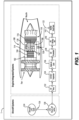
- an aircraft 1 can include an engine 100, where the engine 100 can be a propulsive energy engine (e.g. creating thrust for the aircraft 1), or a non-propulsive energy engine, and a fuel system.
- the engine 100 is a turbofan engine, although the present disclosure may likewise be used with other engine types.
- the engine 100 includes a compressor section 102 having a compressor 104 in a primary gas path 106 to supply compressed air to a combustor 108 of the aircraft engine 100.
- the primary gas path 106 includes a nozzle manifold 110 for issuing fluid to the combustor 108.
- the primary gas path 106 includes, in fluid communication in a series: the compressor 104, the combustor 108 fluidly connected to an outlet 114 of the compressor 104, and a turbine section 116 fluidly connected to an outlet 118 of the combustor 108.
- the turbine section 116 is mechanically connected to the compressor 104 to drive the compressor 104.
- Certain additional components may also be included in fluid communication between the combustor and the gaseous fuel supply 124 in any suitable order or combination, such as a fuel shut off valve 130, a fuel pump 132, a liquid/gaseous fuel evaporator 134, a turbine air cooling heat exchanger 136, a gaseous fuel accumulator 138, a gaseous fuel metering unit 140, and/or a fuel manifold shut off valve 142.
- the pre-pressurized gaseous fuel accumulator 138 can be used as backup supply pressure source.
- a fuel control system 200 for controlling the flow of fuel to the aircraft engine 100 through the feed conduit 122 and the plurality of fuel nozzles 120 includes a means for regulating flow through the fuel feed conduit 122, means for generating a signal indicative of a state of the means for regulating, and a controller 144.
- the controller 144 can include any suitable controller, for example an electronic engine controller (EEC).
- EEC electronic engine controller
- the controller 144 is operatively connected to the means for regulating and to the means for generating a signal to control the means for regulating a signal based on the signal such that the controller is operable to control a state of the means for regulating to achieve a desired power output.
- the means for regulating flow through the fuel feed conduit 122 can include any suitable means, for example can be or include at least one metering valve, an electronic metering valve 146, an electro-pneumatic metering valve, or a combination of valves and/or other devices.
- the means for generating a signal indicative of a state of the electronic metering valve 146 can include any suitable means, for example any number and/or combination of pressure and/or temperature sensors, position sensors, or the like, disposed in the engine 100 and operatively connected as disclosed herein.
- the electronic metering valve 146 is disposed in the fuel feed conduit 122 between the inlet end 126 and the outlet end 128 operable to regulate flow through the fuel feed conduit 122.
- a position feedback sensor 148 is operatively connected to the electronic metering valve 146 and operable to generate a signal 149 indicative of a position of the electronic metering valve 146.
- the position feedback sensor 148 can be or include any suitable position sensor, for example a linear variable differential transformer (LVDT).
- the controller 144 is operatively connected to the electronic metering valve 146 and to the position feedback sensor 148 to control the position of the electronic metering valve 146 based on the signal 149 indicative of the position of the electronic metering valve 146 and a command power 150 for a desired power output of the aircraft engine 100 to achieve the desired power output, e.g. as simultaneous inputs.
- a command power 150 to the controller 144, the position of the electronic metering valve 146 is ultimately driven by a torque motor driver 152 operatively connected to the electronic metering valve 146.
- the controller 144 is configured to control the flow through the fuel nozzles 120 as a function of a plurality signals from a plurality of sensors within the engine 100.
- three fuel pressure sensors 154, 156, 158 can be included.
- the first fuel pressure sensor 154 is operatively connected to the fuel feed conduit 122 upstream of the electronic metering valve 146 and operable to generate a signal 155 indicative of a fuel pressure (P1) in the fuel feed conduit 122 upstream of the electronic metering valve 146.
- the second fuel pressure sensor 156 is operatively connected to the fuel feed conduit 122 downstream of the first pressure sensor 154 to generate a signal 157 indicative of a fuel pressure (P2) in the fuel feed conduit 122 downstream of the electronic metering valve 146 and upstream of the combustor 108.
- the third pressure sensor 158 a delta pressure sensor, can be a differential pressure sensor connected to both a pressure tap 159 in the combustor 108 and to a pressure tap 162 in the fuel feed conduit 122 downstream of the electronic metering valve 146.
- the third pressure sensor 158 is operable to generate and communicate a signal to the controller 144 indicative of a differential pressure between the pressure P2 in the fuel feed conduit 122 and the pressure 159 (P3) of the combustor 108.
- the third pressure sensor 158 can be a differential pressure sensor connected to both pressure taps 162 and 159, or can be an electronic device that takes the difference between two separate pressure sensors in the positions indicated for P2 and P3, including a module of the controller 144 that simply takes the difference between the signals for P2 and P3.
- the controller 144 therefore is operable to control the position of the electronic metering valve 146 based on the each of the signal indicative of an upstream pressure 155, the signal indicative of a downstream pressure 157, and the signal indicative of the difference in pressure 161 between the feed conduit 122 (downstream of the electronic metering valve 146) and the combustor 108.
- a temperature sensor 164 is also operatively connected to the controller 144 such that the controller 144 is operable to control the position of the electronic metering valve 146 based on the signals as described above, in addition to a signal indicative of the fuel temperature 165 in upstream heat exchangers (e.g. 134) which regulate gas temperature at the inlet 126 of the electronic metering valve 146.
- upstream heat exchangers e.g. 134
- Each of the signals 149 indicative of a position of the electronic metering valve 146, the signal 155 indicative of a fuel pressure in the fuel feed conduit 122, the signal 165 indicative of a fuel temperature in the fuel feed conduit 122, the second signal 157 indicative of a fuel pressure in the fuel feed conduit 122, and the signal 159 indicative of the difference in pressure between the fuel feed conduit 122 and the combustor 108 can be input into a control algorithm executable at least in part by the controller 144 to generate a fuel metering control signal as an output based on the plurality of inputs, thus, the controller 144 is operable to control the electronic metering valve 146 by sending the fuel metering signal to the electronic metering valve 146.
- the algorithm could be constructed using the functionality as described above in addition to known general engineering principles as applied to the specific characteristics of each particular fuel system to which the technology of the present disclosure is applied.
- a flow divider assembly 166 is fluidly connected to the outlet 128 end of the fuel feed conduit 122 to divide and issue flow from the fuel feed conduit 122 into the combustor 108 and to the plurality of fuel nozzles 120 through a first fuel manifold 110 and a second fuel manifold 111.
- the first fuel manifold 110 can be a primary fuel manifold configured to provide sufficient fuel during low fuel consumption such as during start up
- the second fuel manifold 111 can be a secondary fuel manifold configured to supplement the primary fuel manifold during high fuel consumption.
- Fuel flow to the first and second fuel manifolds 110, 111 is controlled by a first controlled flow valve 172 is disposed in the first fuel manifold 110, and a second controlled flow valve 174 is disposed in the second fuel manifold 111.
- the first and second controlled flow valves 172, 174 can be any suitable controllable flow valve, such as solenoid valves operatively connected to the controller to selectively energize and de-energize the first and second flow valves 172, 174 to selectively allow flow through the first and second manifolds 110, 111 to the combustor 108.
- the first and second controlled flow valves 172, 174 can be electrohydraulic servo valves operatively connected to the controller 144.
- the energized state corresponds to an open position, where the first and second fuel manifolds 110, 111 are able to issue fuel to the fuel nozzles 120 and the combustor 108 under given engine combustion configurations, and the de-energized state corresponds to a closed position, where the first and second fuel manifolds 110, 111 are prevented from issuing fuel to the fuel nozzles 120 and combustor 108 and fuel flow is cutoff.
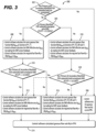
- the controller 144 can control the flow through the first and second fuel manifolds 110, 111 through the first and second controlled flow valves 172, 174 using a method as described below, for example.
- the method 300 includes determining 302 an energized status of the controlled flow valve 172, 174 in the fuel feed conduit 122 and determining 304 whether flow in the fuel feed conduit is subsonic or supersonic. Determining 304 if the flow in the feed conduit is subsonic or supersonic includes calculating a ratio of a second fuel pressure (P2) (e.g. from the signal 157 from the second fuel pressure sensor 156) to a first fuel pressure (P1) (e.g. from the signal 155 from the first fuel pressure sensor 154). If the ratio of second pressure to first pressure (P2/P1) is less than 0.5283, the fuel flow is considered sonic, while if the ratio is greater than or equal to 0.5283, the fuel flow is considered subsonic.
- P2 second fuel pressure
- P1 e.g. from the signal 157 from the second fuel pressure sensor 15
- P1 e.g. from the signal 155 from the first fuel pressure sensor 154
- the method includes controlling 306 a flow rate through the electronic metering valve to achieve zero pounds per hour fuel flow through the electronic metering valve 146, i.e. stopping fuel flow through the electronic metering valve 146.
- the method includes calculating 308 a sonic flow rate ( W f / A fmv ) as a function of the first fuel pressure (P1) in the fuel feed conduit 122 upstream of the electronic metering valve 146 and the fuel temperature (T1) in the fuel feed conduit 122 upstream of the electronic metering valve 146, where fmv effective area Afmv is a calculated by reading the position sensor feedback signal 149.
- the method 300 includes rechecking 310 the energized status of the controlled flow valves 172, 174 and the sonic status of the fuel flow in the fuel feed conduit 122. If both the first and second controlled flow valves 172, 174 are energized, and the flow in the fuel feed conduit 122 is still sonic, the method includes recalculating 312 the sonic flow rate, the effective area, and the required fuel flow as described above with respect to 310. The calculated gaseous fuel flow rate 314 is then outputted to the controller 144 to control the electronic metering valve 146 to control flow in the fuel feed conduit 122 and to the first and second fuel manifolds 110, 111 to achieve the desired gaseous fuel flow rate for the given desired power.
- the method 300 includes calculating 316 a subsonic required fuel flow rate as described below and outputting the calculated gaseous fuel flow rate 314 to the controller 144.
- the method 300 includes calculating 318 a subsonic flow rate ( W f / A fmv ) as a function of the first fuel pressure (P1) in the fuel feed conduit 122 upstream of the electronic metering valve 146, the second fuel pressure (P2) in the fuel feed conduit 122 downstream of the electronic metering valve 146, the delta pressure 161 (e.g.
- the method 300 then includes rechecking 320 the energized status of the controlled flow valves 172, 174 and the sonic status of the fuel flow in the fuel feed conduit 122. If either of the first and second controlled flow valves 172, 174 are de-energized and the fuel flow in the fuel feed conduit is subsonic, the method 300 includes recalculating the subsonic required fuel flow rate as described above with respect to calculating 316. The calculated gaseous fuel flow rate 314 is then outputted to the controller 144 to control the electronic metering valve 146 to control flow in the fuel feed conduit 122 and to the first and second fuel manifolds 110, 111 to achieve the desired gaseous fuel flow rate for the given desired power.
- the method includes calculating the sonic required fuel flow rate as described above with respect to calculating 312, and outputting the calculated gaseous fuel flow rate 314 to the controller 144.
- the method as described herein can be repeated as many times as needed or desired, or may run continuously while fuel is consumed.
Landscapes
- Engineering & Computer Science (AREA)
- Chemical & Material Sciences (AREA)
- Combustion & Propulsion (AREA)
- Mechanical Engineering (AREA)
- General Engineering & Computer Science (AREA)
- Feeding And Controlling Fuel (AREA)
- Physics & Mathematics (AREA)
- General Physics & Mathematics (AREA)
- Automation & Control Theory (AREA)
- Output Control And Ontrol Of Special Type Engine (AREA)
Claims (15)
- Flugzeugmotor (100), umfassend:eine Brennkammer (108); undein Brennstoff-Steuersystem (200), umfassend:eine Brennstoff-Zufuhrleitung (122), die ein Einlassende (126) und ein Auslassende (128) beinhaltet;einen Brennstoff-Dosiermechanismus (146), der in der Brennstoff-Zufuhrleitung (122) zwischen dem Einlassende (126) und dem Auslassende (128) angeordnet und betriebsfähig ist, um den Strom durch die Brennstoff-Zufuhrleitung (122) zu regulieren;einen Positionsrückfuhrsensor (148), der betriebsfähig mit dem Brennstoff-Dosiermechanismus (146) verbunden ist und betriebsfähig ist, um ein Signal zu erzeugen, das eine Position des Brennstoff-Dosiermechanismus (146) angibt;eine Steuerung (144), die betriebsfähig mit dem Brennstoff-Dosiermechanismus (146) und dem Positionsrückfuhrsensor (148) verbunden ist und betriebsfähig ist, um die Position des Brennstoff-Dosiermechanismus (146) basierend auf dem Signal, das die Position des Brennstoff-Dosiermechanismus (146) angibt, und einem Befehl für eine gewünschte Leistungsabgabe des Flugzeugmotors (100) zu steuern, um die gewünschte Leistungsabgabe zu erreichen;einen ersten Brennstoff-Drucksensor (154), der betriebsfähig mit der Brennstoff-Zufuhrleitung (122) verbunden ist und betriebsfähig ist, um ein erstes Signal zu erzeugen, das einen Brennstoffdruck in der Brennstoff-Zufuhrleitung (122) angibt, wobei die Steuerung (144) betriebsfähig mit dem ersten Brennstoff-Drucksensor (154) verbunden ist und betriebsfähig ist, um das erste Signal von dem ersten Brennstoff-Drucksensor (154) zu empfangen, wobei die Steuerung (144) betriebsfähig ist, um die Position des Brennstoff-Dosiermechanismus (146) basierend auf dem ersten Signal, das den Brennstoffdruck in der Brennstoff-Zufuhrleitung (122) angibt, zu steuern;einen zweiten Brennstoff-Drucksensor (156), der betriebsfähig mit der Brennstoff-Zufuhrleitung (122) verbunden ist und betriebsfähig ist, um ein zweites Signal zu erzeugen, das einen Brennstoffdruck in der Brennstoff-Zufuhrleitung (122) angibt, wobei die Steuerung (144) betriebsfähig mit dem zweiten Brennstoff-Drucksensor (156) verbunden ist und betriebsfähig ist, um das zweite Signal von dem zweiten Brennstoff-Drucksensor (156) zu empfangen, wobei die Steuerung (144) betriebsfähig ist, um die Position des Brennstoff-Dosiermechanismus (146) basierend auf dem zweiten Signal, das den Brennstoffdruck in der Brennstoff-Zufuhrleitung (122) angibt, zu steuern;einen Temperatursensor (164), der betriebsfähig mit der Brennstoff-Zufuhrleitung (122) verbunden ist und betriebsfähig ist, um ein Signal zu erzeugen, das eine Brennstofftemperatur in der Brennstoff-Zufuhrleitung (122) angibt, wobei die Steuerung (144) betriebsfähig ist, um die Position des Brennstoff-Dosiermechanismus (146) basierend auf dem Signal, das die Brennstofftemperatur in der Brennstoff-Zufuhrleitung (122) angibt, zu steuern; undeinen Delta-Drucksensor (158), der betriebsfähig mit der Brennstoff-Zufuhrleitung (122) und mit der Brennkammer (108) verbunden ist, wobei der Delta-Drucksensor (158) betriebsfähig ist, um ein Signal (159) zu erzeugen, das einen Druckunterschied zwischen der Brennstoff-Zufuhrleitung (122) und der Brennkammer (108) angibt, wobei die Steuerung (144) betriebsfähig ist, um die Position des Brennstoff-Dosiermechanismus (146) basierend auf dem Signal, das den Druckunterschied zwischen der Brennstoff-Zufuhrleitung (122) und der Brennkammer (108) angibt, zu steuern.
- Flugzeugmotor (100) nach Anspruch 1, wobei der Delta-Drucksensor (158) betriebsfähig über eine von einer zweiten Drucksensoreingangsleitung (162) des zweiten Brennstoff-Drucksensors (156) getrennte Delta-Drucksensorleitung (161) mit der Brennstoff-Zufuhrleitung (122) verbunden ist.
- Flugzeugmotor (100) nach Anspruch 1 oder 2, wobei der erste Brennstoff-Drucksensor (154) in der Brennstoff-Zufuhrleitung (122) stromaufwärts des Brennstoff-Dosiermechanismus (146) angeordnet ist, wobei der zweite Drucksensor (156) in der Brennstoff-Zufuhrleitung (122) stromabwärts des Brennstoff-Dosiermechanismus (146) und stromaufwärts der Brennkammer (108) angeordnet ist, und wobei ein dritter Drucksensor betriebsfähig mit dem Delta-Drucksensor verbunden ist und betriebsfähig ist, um einen Druck der Brennkammer (108) an den Delta-Drucksensor (158) zu kommunizieren.
- Flugzeugmotor (100) nach einem der vorhergehenden Ansprüche, wobei jedes des ersten Signals, das einen Brennstoffdruck in der Brennstoff-Zufuhrleitung (122) angibt, des Signals, das eine Brennstofftemperatur in der Brennstoff-Zufuhrleitung (122) angibt, des zweiten Signals, das einen Brennstoffdruck in der Brennstoff-Zufuhrleitung (122) angibt, und des Signals, das den Druckunterschied zwischen der Brennstoff-Zufuhrleitung (122) und der Brennkammer (108) angibt, eine Vielzahl von Eingaben in einen Steueralgorithmus, der zumindest teilweise durch die Steuerung (144) ausführbar ist, um ein Brennstoff-Dosiermechanismus-Steuersignal als eine Ausgabe basierend auf der Vielzahl von Eingaben zu erzeugen, umfassen, wobei die Steuerung (144) betriebsfähig ist, um den Brennstoff-Dosiermechanismus (146) durch Senden des Brennstoff-Dosiermechanismus-Steuersignals an den Brennstoff-Dosiermechanismus (146) zu steuern.
- Flugzeugmotor (100) nach einem der vorhergehenden Ansprüche, ferner umfassend eine Stromteiler-Baugruppe (166), die mit dem Auslassende (128) der Brennstoff-Zufuhrleitung (122) in Fluidverbindung steht, um den Strom von der Brennstoff-Zufuhrleitung (122) in einen ersten Brennstoffverteiler (110) und einen zweiten Brennstoffverteiler (111) aufzuteilen und abzugeben, wobei der erste und der zweite Brennstoffverteiler (110, 111) in Fluidverbindung stehen, um Brennstoff an eine jeweilige Vielzahl von Brennstoffdüsen (120) abzugeben.
- Flugzeugmotor (100) nach Anspruch 5, ferner umfassend ein erstes gesteuertes Stromventil (172), das in dem ersten Brennstoffverteiler (110) angeordnet ist, und ein zweites gesteuertes Stromventil (174), das in dem zweiten Brennstoffverteiler (111) angeordnet ist.
- Flugzeugmotor (100) nach einem der vorhergehenden Ansprüche, wobei der Brennstoff-Dosiermechanismus (146) mindestens ein Dosierventil ist oder beinhaltet, das betriebsfähig ist, um den Strom durch die Brennstoff-Zufuhrleitung (122) zu regulieren.
- Flugzeugmotor (100) nach einem der vorhergehenden Ansprüche, wobei das Brennstoff-Steuersystem (200) ferner einen Drehmoment-Motortreiber (152) umfasst, der betriebsfähig verbunden ist, um den Brennstoff-Dosiermechanismus (146) bei Empfang eines Befehlssignals von der Steuerung (144) zum Steuern der Position des Brennstoff-Dosiermechanismus (146) durch den Drehmoment-Motortreiber (152) anzutreiben.
- Flugzeugmotor nach einem der vorhergehenden Ansprüche, wobei das Brennstoff-Steuersystem (200) ferner Folgendes umfasst:eine gasförmige, druck- und/oder temperaturgeregelte Brennstoffversorgung (124), die mit dem Einlassende (126) der Brennstoff-Zufuhrleitung (122) in Fluidverbindung steht;eine erste Vielzahl von gasförmigen Wasserstoff-Brennstoffdüsen (120), die über einen ersten Brennstoffverteiler (110) mit dem Auslassende (128) der Brennstoff-Zufuhrleitung (120) in Fluidverbindung stehen; undeine zweite Vielzahl von gasförmigen Wasserstoff-Brennstoffdüsen (120), die über einen zweiten Brennstoffverteiler (111) mit dem Auslassende (128) der Brennstoff-Zufuhrleitung (120) in Fluidverbindung stehen.
- Flugzeugmotor (100) nach Anspruch 9, ferner umfassend:einen Verdichterabschnitt (102), der mit einem Einlass der Brennkammer (108) in Fluidverbindung steht; undeinen Turbinenabschnitt (116), der mit einem Auslass (118) der Brennkammer (108) in Fluidverbindung steht, wobei der Turbinenabschnitt (116) mit dem Verdichterabschnitt (102) betriebsfähig verbunden ist und betriebsfähig ist, um den Verdichterabschnitt (102) anzutreiben;wobei die erste und zweite Vielzahl von Brennstoffdüsen (120) mit der Brennkammer (108) in Fluidverbindung stehen.
- Verfahren zum Steuern von Brennstoffstrom in dem Flugzeugmotor (100) nach einem der vorhergehenden Ansprüche, wobei der Brennstoff-Dosiermechanismus ein elektronisches Brennstoff-Dosierventil (146) ist, wobei das Verfahren Folgendes umfasst:Bestimmen eines eingeschalteten Zustands eines gesteuerten Stromventils in einem Brennstoffverteiler (110, 111);Bestimmen, ob der Strom in einer Brennstoff-Zufuhrleitung (122) schallartig ist;Berechnen einer effektiven Fläche des elektronischen Brennstoff-Dosierventils (146) unter Verwendung eines Signals, das die Position des elektronischen Dosierventils (146) von einem Positionsrückfuhrsensor angibt;Berechnen eines erforderlichen Brennstoffstroms für eine gewünschte Leistungsausgabe; undAnpassen der Position des elektronischen Brennstoff-Dosierventils (146) und/oder des eingeschalteten Zustands des Stromventils, um den erforderlichen Brennstoffstrom basierend auf dem Signal, das die Position des elektronischen Dosierventils (146) angibt, und einem Befehl für eine gewünschte Ausgangsleistung, um die gewünschte Ausgangsleistung zu erreichen.
- Verfahren nach Anspruch 11, ferner umfassend, wenn ein erstes gesteuertes Stromventil (172) und ein zweites gesteuertes Stromventil (174) beide abgeschaltet sind, um Strom zu verhindern,
Steuern der Stromrate durch das elektronische Stromventil (146), um einen Brennstoffstrom von null Pfund pro Stunde durch das elektronische Stromventil (146) zu erreichen. - Verfahren nach Anspruch 11 oder 12, wobei, wenn das erste gesteuerte Stromventil (172) eingeschaltet wird, um Strom zu ermöglichen, und der Strom durch die Zufuhrleitung (122) schallartig ist, dann ferner umfassend das Berechnen einer Schallstromrate in Abhängigkeit von einem ersten Brennstoffdruck in der Brennstoff-Zufuhrleitung (122) stromaufwärts des elektronischen Dosierventils (146) und einer ersten Brennstofftemperatur in der Brennstoff-Zufuhrleitung (122) stromaufwärts des elektronischen Dosierventils (146),
andernfalls, wenn der Strom durch die Leitung (122) unterschallartig ist, ferner umfassend das Berechnen einer Unterschnall-Stromrate in Abhängigkeit von dem ersten Brennstoffdruck, der ersten Brennstofftemperatur, einem zweiten Brennstoffdruck in der Leitung (122) stromabwärts des elektronischen Dosierventils (146) und einer Druckdifferenz zwischen dem zweiten Brennstoffdruck und einem Druck in einer Brennkammer (108) des Flugzeugmotors (100). - Verfahren nach Anspruch 13, ferner umfassend Überprüfen eines eingeschalteten/ausgeschalteten Zustands des ersten gesteuerten Stromventils (172) und des zweiten gesteuerten Stromventils (174) nach dem Berechnen der Überschall- oder Unterschall-Stromrate und Bestimmen, ob der Strom durch die Brennstoff-Zufuhrleitung (122) schallartig ist, durch Wiederholen der Schritte des Berechnens einer Schallstromrate.
- Verfahren nach Anspruch 13 oder 14, ferner umfassend das Berechnen eines Verhältnisses des zweiten Brennstoffdrucks zum ersten Brennstoffdruck und das Bestimmen des Stroms in der Brennstoff-Zufuhrleitung (122) als schallartig, wenn das Verhältnis kleiner als 0,5283 ist, und als unterschallartig, wenn das Verhältnis größer oder gleich 0,5283 ist.
Applications Claiming Priority (1)
| Application Number | Priority Date | Filing Date | Title |
|---|---|---|---|
| US17/386,399 US20230036266A1 (en) | 2021-07-27 | 2021-07-27 | Controlling gaseous fuel flow |
Publications (2)
| Publication Number | Publication Date |
|---|---|
| EP4124735A1 EP4124735A1 (de) | 2023-02-01 |
| EP4124735B1 true EP4124735B1 (de) | 2025-03-19 |
Family
ID=82748559
Family Applications (1)
| Application Number | Title | Priority Date | Filing Date |
|---|---|---|---|
| EP22187338.3A Active EP4124735B1 (de) | 2021-07-27 | 2022-07-27 | Steuern eines gasförmigen brennstoffstroms in einem flugzeugmotor |
Country Status (4)
| Country | Link |
|---|---|
| US (1) | US20230036266A1 (de) |
| EP (1) | EP4124735B1 (de) |
| BR (1) | BR102022014806A2 (de) |
| CA (1) | CA3169133A1 (de) |
Families Citing this family (2)
| Publication number | Priority date | Publication date | Assignee | Title |
|---|---|---|---|---|
| US20240401518A1 (en) * | 2021-10-20 | 2024-12-05 | General Electric Company | Hydrogen fuel system |
| FR3162479A1 (fr) * | 2024-05-22 | 2025-11-28 | Safran Aircraft Engines | Compensation de mesure de debit de carburant gazeux et regulation amelioree de turbomachine |
Family Cites Families (17)
| Publication number | Priority date | Publication date | Assignee | Title |
|---|---|---|---|---|
| US6016832A (en) * | 1997-04-16 | 2000-01-25 | Woodward Governor Company | Valve for controlling gas mass flow |
| US6213758B1 (en) * | 1999-11-09 | 2001-04-10 | Megtec Systems, Inc. | Burner air/fuel ratio regulation method and apparatus |
| JP4102564B2 (ja) * | 2001-12-28 | 2008-06-18 | 忠弘 大見 | 改良型圧力式流量制御装置 |
| US6882924B2 (en) * | 2003-05-05 | 2005-04-19 | Precision Engine Controls Corp. | Valve flow control system and method |
| JP4728176B2 (ja) * | 2005-06-24 | 2011-07-20 | 株式会社日立製作所 | バーナ、ガスタービン燃焼器及びバーナの冷却方法 |
| JP4831820B2 (ja) * | 2006-05-22 | 2011-12-07 | 三菱重工業株式会社 | ガスタービン出力学習回路及びこれを備えたガスタービンの燃焼制御装置 |
| JP4979615B2 (ja) * | 2008-03-05 | 2012-07-18 | 株式会社日立製作所 | 燃焼器及び燃焼器の燃料供給方法 |
| DE102008032565A1 (de) * | 2008-07-11 | 2010-01-14 | Rolls-Royce Deutschland Ltd & Co Kg | Brennstoffzufuhrsystem für ein Gasturbinentriebwerk |
| US8712665B2 (en) * | 2009-11-30 | 2014-04-29 | General Electric Company | Systems and methods for unchoked control of gas turbine fuel gas control valves |
| GB201017166D0 (en) * | 2010-10-12 | 2010-11-24 | Rolls Royce Goodrich Engine Control Systems Ltd | Fuel metering control |
| EP2938852A1 (de) * | 2012-12-28 | 2015-11-04 | General Electric Company | System zur temperatur- und betätigungssteuerung und verfahren zur steuerung von flüssigkeitstemperaturen in einem flugzeug |
| US10317082B2 (en) * | 2014-08-12 | 2019-06-11 | Hamilton Sundstrand Corporation | Distributed fuel control system |
| WO2016172083A1 (en) * | 2015-04-20 | 2016-10-27 | Woodward, Inc. | Gas flow fuel metering |
| US10975776B2 (en) * | 2016-04-07 | 2021-04-13 | Raytheon Technologies Corporation | Adaptive fuel flow estimation with flow meter feedback |
| WO2022003540A1 (en) * | 2020-06-29 | 2022-01-06 | 8 Rivers Capital, Llc | Systems and methods for control of volumetric flows in a power production plant |
| JP7558092B2 (ja) * | 2021-03-12 | 2024-09-30 | 本田技研工業株式会社 | 燃料供給システムおよび燃料供給方法 |
| US12281721B2 (en) * | 2021-05-17 | 2025-04-22 | Honeywell International Inc. | Metering valve with stepper motor-controlled rotary follow-up servo |
-
2021
- 2021-07-27 US US17/386,399 patent/US20230036266A1/en active Pending
-
2022
- 2022-07-26 CA CA3169133A patent/CA3169133A1/en active Pending
- 2022-07-27 BR BR102022014806-6A patent/BR102022014806A2/pt unknown
- 2022-07-27 EP EP22187338.3A patent/EP4124735B1/de active Active
Also Published As
| Publication number | Publication date |
|---|---|
| BR102022014806A2 (pt) | 2023-03-07 |
| US20230036266A1 (en) | 2023-02-02 |
| CA3169133A1 (en) | 2023-01-27 |
| EP4124735A1 (de) | 2023-02-01 |
Similar Documents
| Publication | Publication Date | Title |
|---|---|---|
| EP4134530B1 (de) | Pulsbreitenmodulationsantrieb für gestufte kraftstoffverteiler | |
| GB2563660B (en) | Combustion staging system for fuel injectors of a gas turbine engine | |
| EP4063654A2 (de) | Verstellpumpe mit aktiver bypass-rückkopplungssteuerung | |
| US9353688B2 (en) | High pressure, multiple metering zone gas turbine engine fuel supply system | |
| US6675570B2 (en) | Low-cost general aviation fuel control system | |
| EP2141340B1 (de) | Kraftstoffkontrolleinrichtung einer Gasturbine | |
| US8128378B2 (en) | Dual mode compensation for variable displacement pump fluid metering system | |
| EP2138688B1 (de) | Brennstoffregelungsanordnung | |
| EP4124735B1 (de) | Steuern eines gasförmigen brennstoffstroms in einem flugzeugmotor | |
| KR20050056939A (ko) | 개선된 연료 운반 시스템 | |
| EP2025901B1 (de) | Kraftstoffzumessystem mit minimaler Wärmezuführung | |
| US20260008558A1 (en) | Hydrogen fuel delivery system | |
| US11788476B1 (en) | Fluid system with variable pump discharge pressure and method | |
| US10830444B2 (en) | Combustion staging system | |
| EP4382747B1 (de) | Verstellpumpe mit strömungsabgabe an verschiedene systeme mit unterschiedlichen druckplänen | |
| US12071899B2 (en) | Pump system for a gas turbine engine | |
| US12411503B2 (en) | High turn down ratio direct control for variable displacement pumps with flow sensing | |
| EP2025933B1 (de) | Dualmodus-Kompensierung für ein Pumpmesssystem mit variabler Verdrängung | |
| US20200318644A1 (en) | Rotodynamic pump and method | |
| EP4467797B1 (de) | Direktgesteuerte verstellpumpen mit thermostatisch gesteuertem bypass | |
| US12454950B2 (en) | Direct control for variable displacement pumps using a bypass valve and a minimum pressure shutoff valve | |
| EP4467798B1 (de) | Dosierpumpen mit variabler verdrängung mit direkter steuerung |
Legal Events
| Date | Code | Title | Description |
|---|---|---|---|
| PUAI | Public reference made under article 153(3) epc to a published international application that has entered the european phase |
Free format text: ORIGINAL CODE: 0009012 |
|
| STAA | Information on the status of an ep patent application or granted ep patent |
Free format text: STATUS: THE APPLICATION HAS BEEN PUBLISHED |
|
| AK | Designated contracting states |
Kind code of ref document: A1 Designated state(s): AL AT BE BG CH CY CZ DE DK EE ES FI FR GB GR HR HU IE IS IT LI LT LU LV MC MK MT NL NO PL PT RO RS SE SI SK SM TR |
|
| STAA | Information on the status of an ep patent application or granted ep patent |
Free format text: STATUS: REQUEST FOR EXAMINATION WAS MADE |
|
| 17P | Request for examination filed |
Effective date: 20230801 |
|
| RBV | Designated contracting states (corrected) |
Designated state(s): AL AT BE BG CH CY CZ DE DK EE ES FI FR GB GR HR HU IE IS IT LI LT LU LV MC MK MT NL NO PL PT RO RS SE SI SK SM TR |
|
| GRAP | Despatch of communication of intention to grant a patent |
Free format text: ORIGINAL CODE: EPIDOSNIGR1 |
|
| STAA | Information on the status of an ep patent application or granted ep patent |
Free format text: STATUS: GRANT OF PATENT IS INTENDED |
|
| INTG | Intention to grant announced |
Effective date: 20241004 |
|
| GRAS | Grant fee paid |
Free format text: ORIGINAL CODE: EPIDOSNIGR3 |
|
| GRAA | (expected) grant |
Free format text: ORIGINAL CODE: 0009210 |
|
| STAA | Information on the status of an ep patent application or granted ep patent |
Free format text: STATUS: THE PATENT HAS BEEN GRANTED |
|
| AK | Designated contracting states |
Kind code of ref document: B1 Designated state(s): AL AT BE BG CH CY CZ DE DK EE ES FI FR GB GR HR HU IE IS IT LI LT LU LV MC MK MT NL NO PL PT RO RS SE SI SK SM TR |
|
| REG | Reference to a national code |
Ref country code: GB Ref legal event code: FG4D |
|
| REG | Reference to a national code |
Ref country code: CH Ref legal event code: EP |
|
| REG | Reference to a national code |
Ref country code: DE Ref legal event code: R096 Ref document number: 602022011890 Country of ref document: DE |
|
| REG | Reference to a national code |
Ref country code: IE Ref legal event code: FG4D |
|
| PG25 | Lapsed in a contracting state [announced via postgrant information from national office to epo] |
Ref country code: RS Free format text: LAPSE BECAUSE OF FAILURE TO SUBMIT A TRANSLATION OF THE DESCRIPTION OR TO PAY THE FEE WITHIN THE PRESCRIBED TIME-LIMIT Effective date: 20250619 |
|
| PG25 | Lapsed in a contracting state [announced via postgrant information from national office to epo] |
Ref country code: FI Free format text: LAPSE BECAUSE OF FAILURE TO SUBMIT A TRANSLATION OF THE DESCRIPTION OR TO PAY THE FEE WITHIN THE PRESCRIBED TIME-LIMIT Effective date: 20250319 |
|
| REG | Reference to a national code |
Ref country code: LT Ref legal event code: MG9D |
|
| PG25 | Lapsed in a contracting state [announced via postgrant information from national office to epo] |
Ref country code: NO Free format text: LAPSE BECAUSE OF FAILURE TO SUBMIT A TRANSLATION OF THE DESCRIPTION OR TO PAY THE FEE WITHIN THE PRESCRIBED TIME-LIMIT Effective date: 20250619 |
|
| PG25 | Lapsed in a contracting state [announced via postgrant information from national office to epo] |
Ref country code: HR Free format text: LAPSE BECAUSE OF FAILURE TO SUBMIT A TRANSLATION OF THE DESCRIPTION OR TO PAY THE FEE WITHIN THE PRESCRIBED TIME-LIMIT Effective date: 20250319 |
|
| PG25 | Lapsed in a contracting state [announced via postgrant information from national office to epo] |
Ref country code: LV Free format text: LAPSE BECAUSE OF FAILURE TO SUBMIT A TRANSLATION OF THE DESCRIPTION OR TO PAY THE FEE WITHIN THE PRESCRIBED TIME-LIMIT Effective date: 20250319 |
|
| PGFP | Annual fee paid to national office [announced via postgrant information from national office to epo] |
Ref country code: FR Payment date: 20250620 Year of fee payment: 4 |
|
| PG25 | Lapsed in a contracting state [announced via postgrant information from national office to epo] |
Ref country code: GR Free format text: LAPSE BECAUSE OF FAILURE TO SUBMIT A TRANSLATION OF THE DESCRIPTION OR TO PAY THE FEE WITHIN THE PRESCRIBED TIME-LIMIT Effective date: 20250620 Ref country code: BG Free format text: LAPSE BECAUSE OF FAILURE TO SUBMIT A TRANSLATION OF THE DESCRIPTION OR TO PAY THE FEE WITHIN THE PRESCRIBED TIME-LIMIT Effective date: 20250319 |
|
| REG | Reference to a national code |
Ref country code: NL Ref legal event code: MP Effective date: 20250319 |
|
| REG | Reference to a national code |
Ref country code: AT Ref legal event code: MK05 Ref document number: 1777120 Country of ref document: AT Kind code of ref document: T Effective date: 20250319 |
|
| PG25 | Lapsed in a contracting state [announced via postgrant information from national office to epo] |
Ref country code: NL Free format text: LAPSE BECAUSE OF FAILURE TO SUBMIT A TRANSLATION OF THE DESCRIPTION OR TO PAY THE FEE WITHIN THE PRESCRIBED TIME-LIMIT Effective date: 20250319 |
|
| PG25 | Lapsed in a contracting state [announced via postgrant information from national office to epo] |
Ref country code: SE Free format text: LAPSE BECAUSE OF FAILURE TO SUBMIT A TRANSLATION OF THE DESCRIPTION OR TO PAY THE FEE WITHIN THE PRESCRIBED TIME-LIMIT Effective date: 20250319 |
|
| PG25 | Lapsed in a contracting state [announced via postgrant information from national office to epo] |
Ref country code: SM Free format text: LAPSE BECAUSE OF FAILURE TO SUBMIT A TRANSLATION OF THE DESCRIPTION OR TO PAY THE FEE WITHIN THE PRESCRIBED TIME-LIMIT Effective date: 20250319 |
|
| PG25 | Lapsed in a contracting state [announced via postgrant information from national office to epo] |
Ref country code: ES Free format text: LAPSE BECAUSE OF FAILURE TO SUBMIT A TRANSLATION OF THE DESCRIPTION OR TO PAY THE FEE WITHIN THE PRESCRIBED TIME-LIMIT Effective date: 20250319 Ref country code: PT Free format text: LAPSE BECAUSE OF FAILURE TO SUBMIT A TRANSLATION OF THE DESCRIPTION OR TO PAY THE FEE WITHIN THE PRESCRIBED TIME-LIMIT Effective date: 20250721 |
|
| PGFP | Annual fee paid to national office [announced via postgrant information from national office to epo] |
Ref country code: DE Payment date: 20250620 Year of fee payment: 4 |
|
| PG25 | Lapsed in a contracting state [announced via postgrant information from national office to epo] |
Ref country code: PL Free format text: LAPSE BECAUSE OF FAILURE TO SUBMIT A TRANSLATION OF THE DESCRIPTION OR TO PAY THE FEE WITHIN THE PRESCRIBED TIME-LIMIT Effective date: 20250319 |
|
| PGFP | Annual fee paid to national office [announced via postgrant information from national office to epo] |
Ref country code: IT Payment date: 20250731 Year of fee payment: 4 |
|
| PG25 | Lapsed in a contracting state [announced via postgrant information from national office to epo] |
Ref country code: AT Free format text: LAPSE BECAUSE OF FAILURE TO SUBMIT A TRANSLATION OF THE DESCRIPTION OR TO PAY THE FEE WITHIN THE PRESCRIBED TIME-LIMIT Effective date: 20250319 |
|
| PG25 | Lapsed in a contracting state [announced via postgrant information from national office to epo] |
Ref country code: EE Free format text: LAPSE BECAUSE OF FAILURE TO SUBMIT A TRANSLATION OF THE DESCRIPTION OR TO PAY THE FEE WITHIN THE PRESCRIBED TIME-LIMIT Effective date: 20250319 Ref country code: CZ Free format text: LAPSE BECAUSE OF FAILURE TO SUBMIT A TRANSLATION OF THE DESCRIPTION OR TO PAY THE FEE WITHIN THE PRESCRIBED TIME-LIMIT Effective date: 20250319 |
|
| PG25 | Lapsed in a contracting state [announced via postgrant information from national office to epo] |
Ref country code: RO Free format text: LAPSE BECAUSE OF FAILURE TO SUBMIT A TRANSLATION OF THE DESCRIPTION OR TO PAY THE FEE WITHIN THE PRESCRIBED TIME-LIMIT Effective date: 20250319 |
|
| PG25 | Lapsed in a contracting state [announced via postgrant information from national office to epo] |
Ref country code: SK Free format text: LAPSE BECAUSE OF FAILURE TO SUBMIT A TRANSLATION OF THE DESCRIPTION OR TO PAY THE FEE WITHIN THE PRESCRIBED TIME-LIMIT Effective date: 20250319 |
|
| PG25 | Lapsed in a contracting state [announced via postgrant information from national office to epo] |
Ref country code: IS Free format text: LAPSE BECAUSE OF FAILURE TO SUBMIT A TRANSLATION OF THE DESCRIPTION OR TO PAY THE FEE WITHIN THE PRESCRIBED TIME-LIMIT Effective date: 20250719 |
|
| PG25 | Lapsed in a contracting state [announced via postgrant information from national office to epo] |
Ref country code: DK Free format text: LAPSE BECAUSE OF FAILURE TO SUBMIT A TRANSLATION OF THE DESCRIPTION OR TO PAY THE FEE WITHIN THE PRESCRIBED TIME-LIMIT Effective date: 20250319 |