EP4124735B1 - Controlling gaseous fuel flow in an aircraft engine - Google Patents
Controlling gaseous fuel flow in an aircraft engine Download PDFInfo
- Publication number
- EP4124735B1 EP4124735B1 EP22187338.3A EP22187338A EP4124735B1 EP 4124735 B1 EP4124735 B1 EP 4124735B1 EP 22187338 A EP22187338 A EP 22187338A EP 4124735 B1 EP4124735 B1 EP 4124735B1
- Authority
- EP
- European Patent Office
- Prior art keywords
- fuel
- feed conduit
- flow
- pressure
- operable
- Prior art date
- Legal status (The legal status is an assumption and is not a legal conclusion. Google has not performed a legal analysis and makes no representation as to the accuracy of the status listed.)
- Active
Links
Images

Classifications
-
- F—MECHANICAL ENGINEERING; LIGHTING; HEATING; WEAPONS; BLASTING
- F02—COMBUSTION ENGINES; HOT-GAS OR COMBUSTION-PRODUCT ENGINE PLANTS
- F02C—GAS-TURBINE PLANTS; AIR INTAKES FOR JET-PROPULSION PLANTS; CONTROLLING FUEL SUPPLY IN AIR-BREATHING JET-PROPULSION PLANTS
- F02C9/00—Controlling gas-turbine plants; Controlling fuel supply in air- breathing jet-propulsion plants
- F02C9/26—Control of fuel supply
- F02C9/40—Control of fuel supply specially adapted to the use of a special fuel or a plurality of fuels
-
- F—MECHANICAL ENGINEERING; LIGHTING; HEATING; WEAPONS; BLASTING
- F02—COMBUSTION ENGINES; HOT-GAS OR COMBUSTION-PRODUCT ENGINE PLANTS
- F02C—GAS-TURBINE PLANTS; AIR INTAKES FOR JET-PROPULSION PLANTS; CONTROLLING FUEL SUPPLY IN AIR-BREATHING JET-PROPULSION PLANTS
- F02C3/00—Gas-turbine plants characterised by the use of combustion products as the working fluid
- F02C3/20—Gas-turbine plants characterised by the use of combustion products as the working fluid using a special fuel, oxidant, or dilution fluid to generate the combustion products
- F02C3/22—Gas-turbine plants characterised by the use of combustion products as the working fluid using a special fuel, oxidant, or dilution fluid to generate the combustion products the fuel or oxidant being gaseous at standard temperature and pressure
-
- F—MECHANICAL ENGINEERING; LIGHTING; HEATING; WEAPONS; BLASTING
- F02—COMBUSTION ENGINES; HOT-GAS OR COMBUSTION-PRODUCT ENGINE PLANTS
- F02C—GAS-TURBINE PLANTS; AIR INTAKES FOR JET-PROPULSION PLANTS; CONTROLLING FUEL SUPPLY IN AIR-BREATHING JET-PROPULSION PLANTS
- F02C7/00—Features, components parts, details or accessories, not provided for in, or of interest apart form groups F02C1/00 - F02C6/00; Air intakes for jet-propulsion plants
- F02C7/22—Fuel supply systems
- F02C7/222—Fuel flow conduits, e.g. manifolds
-
- F—MECHANICAL ENGINEERING; LIGHTING; HEATING; WEAPONS; BLASTING
- F02—COMBUSTION ENGINES; HOT-GAS OR COMBUSTION-PRODUCT ENGINE PLANTS
- F02C—GAS-TURBINE PLANTS; AIR INTAKES FOR JET-PROPULSION PLANTS; CONTROLLING FUEL SUPPLY IN AIR-BREATHING JET-PROPULSION PLANTS
- F02C7/00—Features, components parts, details or accessories, not provided for in, or of interest apart form groups F02C1/00 - F02C6/00; Air intakes for jet-propulsion plants
- F02C7/22—Fuel supply systems
- F02C7/232—Fuel valves; Draining valves or systems
-
- F—MECHANICAL ENGINEERING; LIGHTING; HEATING; WEAPONS; BLASTING
- F02—COMBUSTION ENGINES; HOT-GAS OR COMBUSTION-PRODUCT ENGINE PLANTS
- F02C—GAS-TURBINE PLANTS; AIR INTAKES FOR JET-PROPULSION PLANTS; CONTROLLING FUEL SUPPLY IN AIR-BREATHING JET-PROPULSION PLANTS
- F02C9/00—Controlling gas-turbine plants; Controlling fuel supply in air- breathing jet-propulsion plants
- F02C9/26—Control of fuel supply
- F02C9/263—Control of fuel supply by means of fuel metering valves
-
- F—MECHANICAL ENGINEERING; LIGHTING; HEATING; WEAPONS; BLASTING
- F05—INDEXING SCHEMES RELATING TO ENGINES OR PUMPS IN VARIOUS SUBCLASSES OF CLASSES F01-F04
- F05D—INDEXING SCHEME FOR ASPECTS RELATING TO NON-POSITIVE-DISPLACEMENT MACHINES OR ENGINES, GAS-TURBINES OR JET-PROPULSION PLANTS
- F05D2270/00—Control
- F05D2270/01—Purpose of the control system
- F05D2270/05—Purpose of the control system to affect the output of the engine
- F05D2270/051—Thrust
-
- F—MECHANICAL ENGINEERING; LIGHTING; HEATING; WEAPONS; BLASTING
- F05—INDEXING SCHEMES RELATING TO ENGINES OR PUMPS IN VARIOUS SUBCLASSES OF CLASSES F01-F04
- F05D—INDEXING SCHEME FOR ASPECTS RELATING TO NON-POSITIVE-DISPLACEMENT MACHINES OR ENGINES, GAS-TURBINES OR JET-PROPULSION PLANTS
- F05D2270/00—Control
- F05D2270/01—Purpose of the control system
- F05D2270/05—Purpose of the control system to affect the output of the engine
- F05D2270/053—Explicitly mentioned power
-
- F—MECHANICAL ENGINEERING; LIGHTING; HEATING; WEAPONS; BLASTING
- F05—INDEXING SCHEMES RELATING TO ENGINES OR PUMPS IN VARIOUS SUBCLASSES OF CLASSES F01-F04
- F05D—INDEXING SCHEME FOR ASPECTS RELATING TO NON-POSITIVE-DISPLACEMENT MACHINES OR ENGINES, GAS-TURBINES OR JET-PROPULSION PLANTS
- F05D2270/00—Control
- F05D2270/30—Control parameters, e.g. input parameters
- F05D2270/301—Pressure
- F05D2270/3015—Pressure differential pressure
-
- F—MECHANICAL ENGINEERING; LIGHTING; HEATING; WEAPONS; BLASTING
- F05—INDEXING SCHEMES RELATING TO ENGINES OR PUMPS IN VARIOUS SUBCLASSES OF CLASSES F01-F04
- F05D—INDEXING SCHEME FOR ASPECTS RELATING TO NON-POSITIVE-DISPLACEMENT MACHINES OR ENGINES, GAS-TURBINES OR JET-PROPULSION PLANTS
- F05D2270/00—Control
- F05D2270/30—Control parameters, e.g. input parameters
- F05D2270/303—Temperature
-
- F—MECHANICAL ENGINEERING; LIGHTING; HEATING; WEAPONS; BLASTING
- F05—INDEXING SCHEMES RELATING TO ENGINES OR PUMPS IN VARIOUS SUBCLASSES OF CLASSES F01-F04
- F05D—INDEXING SCHEME FOR ASPECTS RELATING TO NON-POSITIVE-DISPLACEMENT MACHINES OR ENGINES, GAS-TURBINES OR JET-PROPULSION PLANTS
- F05D2270/00—Control
- F05D2270/30—Control parameters, e.g. input parameters
- F05D2270/306—Mass flow
-
- F—MECHANICAL ENGINEERING; LIGHTING; HEATING; WEAPONS; BLASTING
- F05—INDEXING SCHEMES RELATING TO ENGINES OR PUMPS IN VARIOUS SUBCLASSES OF CLASSES F01-F04
- F05D—INDEXING SCHEME FOR ASPECTS RELATING TO NON-POSITIVE-DISPLACEMENT MACHINES OR ENGINES, GAS-TURBINES OR JET-PROPULSION PLANTS
- F05D2270/00—Control
- F05D2270/80—Devices generating input signals, e.g. transducers, sensors, cameras or strain gauges
- F05D2270/821—Displacement measuring means, e.g. inductive
Definitions
- US 2005/021213 A1 discloses a prior art valve flow control system and method.
- EP 3 228 847 A1 discloses a prior art aircraft engine with adaptive fuel flow estimation having flow meter feedback.
- an aircraft engine as set forth in claim 1.
- the first fuel pressure sensor is disposed in the fuel feed conduit upstream of the fuel metering mechanism
- the second pressure sensor is disposed in the fuel feed conduit downstream of the fuel metering mechanism and upstream of the combustor
- a third pressure sensor is connected to the delta pressure sensor such that the third pressure sensor is operable to communicate a pressure of the combustor to the delta pressure sensor.
- the delta pressure sensor operatively connects to the feed conduit via a delta pressure sensor line separate from a second pressure sensor input line of the second fuel pressure sensor.
- a gaseous pressure and/or temperature regulated fuel supply is fluidly connected to the inlet end of the fuel feed conduit.
- a first plurality of gaseous hydrogen fuel nozzles is fluidly connected to the outlet end of the fuel feed conduit via a first fuel manifold.
- a second plurality of gaseous hydrogen fuel nozzles is fluidly connected to the outlet end of the fuel feed conduit via the second fuel manifold.
- the method includes calculating a sonic flow rate as a function of a first fuel pressure in the fuel feed conduit upstream of the electronic metering valve and a first fuel temperature in the fuel feed conduit upstream of the electronic metering valve.
- the method includes calculating a subsonic flow rate as a function of the first fuel pressure, the first fuel temperature, a second fuel pressure in the feed conduit downstream of the electronic metering valve, and a pressure differential between the second fuel pressure and a pressure in a combustor of the aircraft engine.
- an aircraft 1 can include an engine 100, where the engine 100 can be a propulsive energy engine (e.g. creating thrust for the aircraft 1), or a non-propulsive energy engine, and a fuel system.
- the engine 100 is a turbofan engine, although the present disclosure may likewise be used with other engine types.
- the engine 100 includes a compressor section 102 having a compressor 104 in a primary gas path 106 to supply compressed air to a combustor 108 of the aircraft engine 100.
- the primary gas path 106 includes a nozzle manifold 110 for issuing fluid to the combustor 108.
- the primary gas path 106 includes, in fluid communication in a series: the compressor 104, the combustor 108 fluidly connected to an outlet 114 of the compressor 104, and a turbine section 116 fluidly connected to an outlet 118 of the combustor 108.
- the turbine section 116 is mechanically connected to the compressor 104 to drive the compressor 104.
- Certain additional components may also be included in fluid communication between the combustor and the gaseous fuel supply 124 in any suitable order or combination, such as a fuel shut off valve 130, a fuel pump 132, a liquid/gaseous fuel evaporator 134, a turbine air cooling heat exchanger 136, a gaseous fuel accumulator 138, a gaseous fuel metering unit 140, and/or a fuel manifold shut off valve 142.
- the pre-pressurized gaseous fuel accumulator 138 can be used as backup supply pressure source.
- a fuel control system 200 for controlling the flow of fuel to the aircraft engine 100 through the feed conduit 122 and the plurality of fuel nozzles 120 includes a means for regulating flow through the fuel feed conduit 122, means for generating a signal indicative of a state of the means for regulating, and a controller 144.
- the controller 144 can include any suitable controller, for example an electronic engine controller (EEC).
- EEC electronic engine controller
- the controller 144 is operatively connected to the means for regulating and to the means for generating a signal to control the means for regulating a signal based on the signal such that the controller is operable to control a state of the means for regulating to achieve a desired power output.
- the means for regulating flow through the fuel feed conduit 122 can include any suitable means, for example can be or include at least one metering valve, an electronic metering valve 146, an electro-pneumatic metering valve, or a combination of valves and/or other devices.
- the means for generating a signal indicative of a state of the electronic metering valve 146 can include any suitable means, for example any number and/or combination of pressure and/or temperature sensors, position sensors, or the like, disposed in the engine 100 and operatively connected as disclosed herein.
- the electronic metering valve 146 is disposed in the fuel feed conduit 122 between the inlet end 126 and the outlet end 128 operable to regulate flow through the fuel feed conduit 122.
- a position feedback sensor 148 is operatively connected to the electronic metering valve 146 and operable to generate a signal 149 indicative of a position of the electronic metering valve 146.
- the position feedback sensor 148 can be or include any suitable position sensor, for example a linear variable differential transformer (LVDT).
- the controller 144 is operatively connected to the electronic metering valve 146 and to the position feedback sensor 148 to control the position of the electronic metering valve 146 based on the signal 149 indicative of the position of the electronic metering valve 146 and a command power 150 for a desired power output of the aircraft engine 100 to achieve the desired power output, e.g. as simultaneous inputs.
- a command power 150 to the controller 144, the position of the electronic metering valve 146 is ultimately driven by a torque motor driver 152 operatively connected to the electronic metering valve 146.
- the controller 144 is configured to control the flow through the fuel nozzles 120 as a function of a plurality signals from a plurality of sensors within the engine 100.
- three fuel pressure sensors 154, 156, 158 can be included.
- the first fuel pressure sensor 154 is operatively connected to the fuel feed conduit 122 upstream of the electronic metering valve 146 and operable to generate a signal 155 indicative of a fuel pressure (P1) in the fuel feed conduit 122 upstream of the electronic metering valve 146.
- the second fuel pressure sensor 156 is operatively connected to the fuel feed conduit 122 downstream of the first pressure sensor 154 to generate a signal 157 indicative of a fuel pressure (P2) in the fuel feed conduit 122 downstream of the electronic metering valve 146 and upstream of the combustor 108.
- the third pressure sensor 158 a delta pressure sensor, can be a differential pressure sensor connected to both a pressure tap 159 in the combustor 108 and to a pressure tap 162 in the fuel feed conduit 122 downstream of the electronic metering valve 146.
- the third pressure sensor 158 is operable to generate and communicate a signal to the controller 144 indicative of a differential pressure between the pressure P2 in the fuel feed conduit 122 and the pressure 159 (P3) of the combustor 108.
- the third pressure sensor 158 can be a differential pressure sensor connected to both pressure taps 162 and 159, or can be an electronic device that takes the difference between two separate pressure sensors in the positions indicated for P2 and P3, including a module of the controller 144 that simply takes the difference between the signals for P2 and P3.
- the controller 144 therefore is operable to control the position of the electronic metering valve 146 based on the each of the signal indicative of an upstream pressure 155, the signal indicative of a downstream pressure 157, and the signal indicative of the difference in pressure 161 between the feed conduit 122 (downstream of the electronic metering valve 146) and the combustor 108.
- a temperature sensor 164 is also operatively connected to the controller 144 such that the controller 144 is operable to control the position of the electronic metering valve 146 based on the signals as described above, in addition to a signal indicative of the fuel temperature 165 in upstream heat exchangers (e.g. 134) which regulate gas temperature at the inlet 126 of the electronic metering valve 146.
- upstream heat exchangers e.g. 134
- Each of the signals 149 indicative of a position of the electronic metering valve 146, the signal 155 indicative of a fuel pressure in the fuel feed conduit 122, the signal 165 indicative of a fuel temperature in the fuel feed conduit 122, the second signal 157 indicative of a fuel pressure in the fuel feed conduit 122, and the signal 159 indicative of the difference in pressure between the fuel feed conduit 122 and the combustor 108 can be input into a control algorithm executable at least in part by the controller 144 to generate a fuel metering control signal as an output based on the plurality of inputs, thus, the controller 144 is operable to control the electronic metering valve 146 by sending the fuel metering signal to the electronic metering valve 146.
- the algorithm could be constructed using the functionality as described above in addition to known general engineering principles as applied to the specific characteristics of each particular fuel system to which the technology of the present disclosure is applied.
- a flow divider assembly 166 is fluidly connected to the outlet 128 end of the fuel feed conduit 122 to divide and issue flow from the fuel feed conduit 122 into the combustor 108 and to the plurality of fuel nozzles 120 through a first fuel manifold 110 and a second fuel manifold 111.
- the first fuel manifold 110 can be a primary fuel manifold configured to provide sufficient fuel during low fuel consumption such as during start up
- the second fuel manifold 111 can be a secondary fuel manifold configured to supplement the primary fuel manifold during high fuel consumption.
- Fuel flow to the first and second fuel manifolds 110, 111 is controlled by a first controlled flow valve 172 is disposed in the first fuel manifold 110, and a second controlled flow valve 174 is disposed in the second fuel manifold 111.
- the first and second controlled flow valves 172, 174 can be any suitable controllable flow valve, such as solenoid valves operatively connected to the controller to selectively energize and de-energize the first and second flow valves 172, 174 to selectively allow flow through the first and second manifolds 110, 111 to the combustor 108.
- the first and second controlled flow valves 172, 174 can be electrohydraulic servo valves operatively connected to the controller 144.
- the energized state corresponds to an open position, where the first and second fuel manifolds 110, 111 are able to issue fuel to the fuel nozzles 120 and the combustor 108 under given engine combustion configurations, and the de-energized state corresponds to a closed position, where the first and second fuel manifolds 110, 111 are prevented from issuing fuel to the fuel nozzles 120 and combustor 108 and fuel flow is cutoff.
- the controller 144 can control the flow through the first and second fuel manifolds 110, 111 through the first and second controlled flow valves 172, 174 using a method as described below, for example.
- the method 300 includes determining 302 an energized status of the controlled flow valve 172, 174 in the fuel feed conduit 122 and determining 304 whether flow in the fuel feed conduit is subsonic or supersonic. Determining 304 if the flow in the feed conduit is subsonic or supersonic includes calculating a ratio of a second fuel pressure (P2) (e.g. from the signal 157 from the second fuel pressure sensor 156) to a first fuel pressure (P1) (e.g. from the signal 155 from the first fuel pressure sensor 154). If the ratio of second pressure to first pressure (P2/P1) is less than 0.5283, the fuel flow is considered sonic, while if the ratio is greater than or equal to 0.5283, the fuel flow is considered subsonic.
- P2 second fuel pressure
- P1 e.g. from the signal 157 from the second fuel pressure sensor 15
- P1 e.g. from the signal 155 from the first fuel pressure sensor 154
- the method includes controlling 306 a flow rate through the electronic metering valve to achieve zero pounds per hour fuel flow through the electronic metering valve 146, i.e. stopping fuel flow through the electronic metering valve 146.
- the method includes calculating 308 a sonic flow rate ( W f / A fmv ) as a function of the first fuel pressure (P1) in the fuel feed conduit 122 upstream of the electronic metering valve 146 and the fuel temperature (T1) in the fuel feed conduit 122 upstream of the electronic metering valve 146, where fmv effective area Afmv is a calculated by reading the position sensor feedback signal 149.
- the method 300 includes rechecking 310 the energized status of the controlled flow valves 172, 174 and the sonic status of the fuel flow in the fuel feed conduit 122. If both the first and second controlled flow valves 172, 174 are energized, and the flow in the fuel feed conduit 122 is still sonic, the method includes recalculating 312 the sonic flow rate, the effective area, and the required fuel flow as described above with respect to 310. The calculated gaseous fuel flow rate 314 is then outputted to the controller 144 to control the electronic metering valve 146 to control flow in the fuel feed conduit 122 and to the first and second fuel manifolds 110, 111 to achieve the desired gaseous fuel flow rate for the given desired power.
- the method 300 includes calculating 316 a subsonic required fuel flow rate as described below and outputting the calculated gaseous fuel flow rate 314 to the controller 144.
- the method 300 includes calculating 318 a subsonic flow rate ( W f / A fmv ) as a function of the first fuel pressure (P1) in the fuel feed conduit 122 upstream of the electronic metering valve 146, the second fuel pressure (P2) in the fuel feed conduit 122 downstream of the electronic metering valve 146, the delta pressure 161 (e.g.
- the method 300 then includes rechecking 320 the energized status of the controlled flow valves 172, 174 and the sonic status of the fuel flow in the fuel feed conduit 122. If either of the first and second controlled flow valves 172, 174 are de-energized and the fuel flow in the fuel feed conduit is subsonic, the method 300 includes recalculating the subsonic required fuel flow rate as described above with respect to calculating 316. The calculated gaseous fuel flow rate 314 is then outputted to the controller 144 to control the electronic metering valve 146 to control flow in the fuel feed conduit 122 and to the first and second fuel manifolds 110, 111 to achieve the desired gaseous fuel flow rate for the given desired power.
- the method includes calculating the sonic required fuel flow rate as described above with respect to calculating 312, and outputting the calculated gaseous fuel flow rate 314 to the controller 144.
- the method as described herein can be repeated as many times as needed or desired, or may run continuously while fuel is consumed.
Landscapes
- Engineering & Computer Science (AREA)
- Chemical & Material Sciences (AREA)
- Combustion & Propulsion (AREA)
- Mechanical Engineering (AREA)
- General Engineering & Computer Science (AREA)
- Feeding And Controlling Fuel (AREA)
- Physics & Mathematics (AREA)
- General Physics & Mathematics (AREA)
- Automation & Control Theory (AREA)
- Output Control And Ontrol Of Special Type Engine (AREA)
Description
- There is an ongoing need for accurate control systems and methods for handling gaseous fuel like hydrogen over a range of operating conditions such as in aircraft operation.
-
US 2005/021213 A1 discloses a prior art valve flow control system and method. -
EP 3 228 847 A1 discloses a prior art aircraft engine with adaptive fuel flow estimation having flow meter feedback. - According to a first aspect of the present invention, there is provided an aircraft engine as set forth in claim 1.
- In certain embodiments, the first fuel pressure sensor is disposed in the fuel feed conduit upstream of the fuel metering mechanism, the second pressure sensor is disposed in the fuel feed conduit downstream of the fuel metering mechanism and upstream of the combustor, and a third pressure sensor is connected to the delta pressure sensor such that the third pressure sensor is operable to communicate a pressure of the combustor to the delta pressure sensor. In certain such embodiments, the delta pressure sensor operatively connects to the feed conduit via a delta pressure sensor line separate from a second pressure sensor input line of the second fuel pressure sensor.
- In embodiments, each of the signal indicative of a fuel pressure in the fuel feed conduit, the signal indicative of a fuel temperature in the fuel feed conduit, the second signal indicative of a fuel pressure in the fuel feed conduit, and the signal indicative of the difference in pressure between the fuel feed conduit and the combustor comprise a plurality inputs to a control algorithm executable at least in part by the controller to generate a fuel metering mechanism control signal as an output based on the plurality of inputs, wherein the controller is operable to control the fuel metering mechanism by sending the fuel metering mechanism signal to the fuel metering mechanism.
- In embodiments, a flow divider assembly is fluidly connected to the outlet end of the fuel feed conduit to divide and issue flow from the fuel feed conduit into a first fuel manifold and a second fuel manifold, the first and second fuel manifolds being fluidly connected to issue fuel to a respective plurality of fuel nozzles. In certain embodiments, a first controlled flow valve is disposed in the first fuel manifold, and a second controlled flow valve is disposed in the second fuel manifold. In certain such embodiments, the first and second controlled flow valves can be solenoid valves operatively connected to the controller to selectively energize and de-energize the first and second flow valves to selectively allow flow through the first and second manifolds. In certain such embodiments, the first and second controlled flow valves can be electrohydraulic servo valves operatively connected to the controller to selectively control the first and second flow valves to selectively allow flow through the first and second manifolds.
- In embodiments, a gaseous pressure and/or temperature regulated fuel supply is fluidly connected to the inlet end of the fuel feed conduit. A first plurality of gaseous hydrogen fuel nozzles is fluidly connected to the outlet end of the fuel feed conduit via a first fuel manifold. A second plurality of gaseous hydrogen fuel nozzles is fluidly connected to the outlet end of the fuel feed conduit via the second fuel manifold.
- In embodiments, the system comprises a compressor section fluidly connected to an inlet of the combustor; and a turbine section fluidly connected to an outlet of the combustor. The first and second pluralities of fuel nozzles are fluidly connected to the combustor and wherein the turbine section is operatively connected to the compressor section and operable to drive the compressor section.
- According to a further aspect of the present invention, there is provided a method for controlling fuel flow in an aircraft engine as set forth in claim 11.
- In embodiments, if a first controlled flow valve and second controlled flow valve are both de-energized to prevent flow, the method includes controlling a flow rate through the electronic metering valve to achieve zero pounds per hour fuel flow through the electronic metering valve.
- In embodiments, if the first controlled flow valve is energized to allow flow and the flow through the feed conduit is sonic, the method includes calculating a sonic flow rate as a function of a first fuel pressure in the fuel feed conduit upstream of the electronic metering valve and a first fuel temperature in the fuel feed conduit upstream of the electronic metering valve. In all other instances, if the flow through the fuel feed conduit is sub-sonic, the method includes calculating a subsonic flow rate as a function of the first fuel pressure, the first fuel temperature, a second fuel pressure in the feed conduit downstream of the electronic metering valve, and a pressure differential between the second fuel pressure and a pressure in a combustor of the aircraft engine.
- In embodiments, the method includes, after calculating the supersonic flow rate or subsonic flow rate, checking an energized/de-energized status of the first controlled flow valve and of the second controlled flow valve and determining whether the flow through the fuel feed conduit is sonic repeating the steps of the method described above.
- In embodiments, the method includes calculating a ratio of the second fuel pressure to the first fuel pressure, and determining the flow in the fuel feed conduit is sonic if the ratio is less than 0.5283 and is subsonic if the ratio is greater than or equal to 0.5283.
- These and other features of the embodiments of the subject disclosure will become more readily apparent to those skilled in the art from the following detailed description taken in conjunction with the drawings.
- So that those skilled in the art to which the subject disclosure appertains will readily understand how to make and use the devices and methods of the subject disclosure without undue experimentation, embodiments thereof will be described in detail herein below with reference to certain figures, wherein:
-
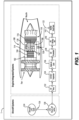
Fig. 1 is schematic cross-sectional side elevation view an aircraft engine in accordance with this disclosure, showing a plurality of fuel components connecting a fuel source to a combustor; -
Fig. 2 is a schematic view of an embodiment of a fuel control system for the engine ofFig.1 constructed in accordance with at least one aspect of this disclosure; and -
Fig. 3 is a schematic flow diagram of a method of operating the control system ofFig. 2 constructed in accordance with at least one aspect of this disclosure. - Reference will now be made to the drawings wherein like reference numerals identify similar structural features or aspects of the subject disclosure. For purposes of explanation and illustration, and not limitation, an illustrative view of an embodiment of a system in accordance with the disclosure is shown in
Fig. 1 and is designated generally byreference character 100. Other embodiments and/or aspects of this disclosure are shown inFigs. 2-3 . Certain embodiments described herein can be used to improve fuel metering for gaseous fuel, e.g. compressible fuels such as hydrogen gas. - The present disclosure relates generally to fuel control for gas turbine engines, and more particularly to control of gaseous fuel flow. A gas turbine engine may be fueled with gaseous fuel such as hydrogen gas. It is possible to gasify liquid hydrogen from an aircraft supply through an appropriate fuel pump, heat exchangers, pressure regulator, and metering valves. It is desired to control gaseous fuel delivery to the engine such that stable and responsive control over the wide range of flow conditions would be maintained. However, the traditional fuel control for aircraft engines are designed for purely liquid fuel flow. Liquid fuel is an incompressible fluid, whereas gaseous fuel is compressible. For hydrogen, the full fuel system can include a combination of liquid and gaseous hydrogen, meaning the fuel control system needs to control both compressible and incompressible flows.
- The gaseous hydrogen is pressurized from the fuel delivering system so that pressure supplied to the fuel line P1 is regulated at a much higher pressure of the burner pressure P3 (e.g. at least double). Therefore, variation of fuel metering valve output sets a variable throat area to the valve which is maintained choked (e.g. in a sonic state) at all system flow conditions.
- In certain embodiments, referring to
Fig. 1 , an aircraft 1 can include anengine 100, where theengine 100 can be a propulsive energy engine (e.g. creating thrust for the aircraft 1), or a non-propulsive energy engine, and a fuel system. As described herein, theengine 100 is a turbofan engine, although the present disclosure may likewise be used with other engine types. Theengine 100 includes acompressor section 102 having acompressor 104 in aprimary gas path 106 to supply compressed air to acombustor 108 of theaircraft engine 100. Theprimary gas path 106 includes anozzle manifold 110 for issuing fluid to thecombustor 108. - The
primary gas path 106 includes, in fluid communication in a series: thecompressor 104, thecombustor 108 fluidly connected to anoutlet 114 of thecompressor 104, and aturbine section 116 fluidly connected to anoutlet 118 of thecombustor 108. Theturbine section 116 is mechanically connected to thecompressor 104 to drive thecompressor 104. - The
combustor 108 includes a plurality offuel nozzles 120 each fluidly connected via afuel feed conduit 122, which feeds thenozzle manifold 110, which feeds the plurality offuel nozzles 120 of thecombustor 108 with agaseous fuel supply 124. Thefeed conduit 122 includes aninlet end 126 and anoutlet end 128 to fluidly connect thegaseous fuel supply 124 to thecombustor 108 through the plurality offuel nozzles 120. In embodiments, thegaseous fuel supply 124 can be any suitable gaseous fuel, such as a gaseous pressure and/or temperature regulated fuel supply, which may be or include hydrogen gas. - Certain additional components may also be included in fluid communication between the combustor and the
gaseous fuel supply 124 in any suitable order or combination, such as a fuel shut offvalve 130, afuel pump 132, a liquid/gaseous fuel evaporator 134, a turbine aircooling heat exchanger 136, agaseous fuel accumulator 138, a gaseous fuel metering unit 140, and/or a fuel manifold shut offvalve 142. In certain embodiments, the pre-pressurizedgaseous fuel accumulator 138 can be used as backup supply pressure source. - Turning now to
Fig. 2 , afuel control system 200 for controlling the flow of fuel to theaircraft engine 100 through thefeed conduit 122 and the plurality offuel nozzles 120 includes a means for regulating flow through thefuel feed conduit 122, means for generating a signal indicative of a state of the means for regulating, and acontroller 144. Thecontroller 144 can include any suitable controller, for example an electronic engine controller (EEC). Thecontroller 144 is operatively connected to the means for regulating and to the means for generating a signal to control the means for regulating a signal based on the signal such that the controller is operable to control a state of the means for regulating to achieve a desired power output. - As described herein, the means for regulating flow through the fuel feed conduit 122 (e.g. fuel metering mechanism) can include any suitable means, for example can be or include at least one metering valve, an
electronic metering valve 146, an electro-pneumatic metering valve, or a combination of valves and/or other devices. The means for generating a signal indicative of a state of theelectronic metering valve 146 can include any suitable means, for example any number and/or combination of pressure and/or temperature sensors, position sensors, or the like, disposed in theengine 100 and operatively connected as disclosed herein. - As shown in
Fig. 2 , theelectronic metering valve 146 is disposed in thefuel feed conduit 122 between theinlet end 126 and theoutlet end 128 operable to regulate flow through thefuel feed conduit 122. Aposition feedback sensor 148 is operatively connected to theelectronic metering valve 146 and operable to generate asignal 149 indicative of a position of theelectronic metering valve 146. Theposition feedback sensor 148 can be or include any suitable position sensor, for example a linear variable differential transformer (LVDT). - The
controller 144 is operatively connected to theelectronic metering valve 146 and to theposition feedback sensor 148 to control the position of theelectronic metering valve 146 based on thesignal 149 indicative of the position of theelectronic metering valve 146 and acommand power 150 for a desired power output of theaircraft engine 100 to achieve the desired power output, e.g. as simultaneous inputs. Upon receipt of acommand power 150 to thecontroller 144, the position of theelectronic metering valve 146 is ultimately driven by atorque motor driver 152 operatively connected to theelectronic metering valve 146. - In addition to position feedback from the
position feedback sensor 148, thecontroller 144 is configured to control the flow through thefuel nozzles 120 as a function of a plurality signals from a plurality of sensors within theengine 100. For example, threefuel pressure sensors fuel pressure sensor 154 is operatively connected to thefuel feed conduit 122 upstream of theelectronic metering valve 146 and operable to generate asignal 155 indicative of a fuel pressure (P1) in thefuel feed conduit 122 upstream of theelectronic metering valve 146. The secondfuel pressure sensor 156 is operatively connected to thefuel feed conduit 122 downstream of thefirst pressure sensor 154 to generate asignal 157 indicative of a fuel pressure (P2) in thefuel feed conduit 122 downstream of theelectronic metering valve 146 and upstream of thecombustor 108. Thethird pressure sensor 158, a delta pressure sensor, can be a differential pressure sensor connected to both apressure tap 159 in thecombustor 108 and to apressure tap 162 in thefuel feed conduit 122 downstream of theelectronic metering valve 146. Thethird pressure sensor 158, is operable to generate and communicate a signal to thecontroller 144 indicative of a differential pressure between the pressure P2 in thefuel feed conduit 122 and the pressure 159 (P3) of thecombustor 108. Thethird pressure sensor 158 can be a differential pressure sensor connected to both pressure taps 162 and 159, or can be an electronic device that takes the difference between two separate pressure sensors in the positions indicated for P2 and P3, including a module of thecontroller 144 that simply takes the difference between the signals for P2 and P3. - The
controller 144 therefore is operable to control the position of theelectronic metering valve 146 based on the each of the signal indicative of anupstream pressure 155, the signal indicative of adownstream pressure 157, and the signal indicative of the difference inpressure 161 between the feed conduit 122 (downstream of the electronic metering valve 146) and thecombustor 108. - In certain embodiments, a
temperature sensor 164 is also operatively connected to thecontroller 144 such that thecontroller 144 is operable to control the position of theelectronic metering valve 146 based on the signals as described above, in addition to a signal indicative of thefuel temperature 165 in upstream heat exchangers (e.g. 134) which regulate gas temperature at theinlet 126 of theelectronic metering valve 146. - Each of the
signals 149 indicative of a position of theelectronic metering valve 146, thesignal 155 indicative of a fuel pressure in thefuel feed conduit 122, thesignal 165 indicative of a fuel temperature in thefuel feed conduit 122, thesecond signal 157 indicative of a fuel pressure in thefuel feed conduit 122, and thesignal 159 indicative of the difference in pressure between thefuel feed conduit 122 and thecombustor 108 can be input into a control algorithm executable at least in part by thecontroller 144 to generate a fuel metering control signal as an output based on the plurality of inputs, thus, thecontroller 144 is operable to control theelectronic metering valve 146 by sending the fuel metering signal to theelectronic metering valve 146. In embodiments, the algorithm could be constructed using the functionality as described above in addition to known general engineering principles as applied to the specific characteristics of each particular fuel system to which the technology of the present disclosure is applied. - In embodiments, a
flow divider assembly 166 is fluidly connected to theoutlet 128 end of thefuel feed conduit 122 to divide and issue flow from thefuel feed conduit 122 into thecombustor 108 and to the plurality offuel nozzles 120 through afirst fuel manifold 110 and asecond fuel manifold 111. Thefirst fuel manifold 110 can be a primary fuel manifold configured to provide sufficient fuel during low fuel consumption such as during start up, and thesecond fuel manifold 111 can be a secondary fuel manifold configured to supplement the primary fuel manifold during high fuel consumption. - Fuel flow to the first and
second fuel manifolds flow valve 172 is disposed in thefirst fuel manifold 110, and a second controlledflow valve 174 is disposed in thesecond fuel manifold 111. The first and second controlledflow valves second flow valves second manifolds combustor 108. In certain embodiments, the first and second controlledflow valves controller 144. The energized state corresponds to an open position, where the first andsecond fuel manifolds fuel nozzles 120 and thecombustor 108 under given engine combustion configurations, and the de-energized state corresponds to a closed position, where the first andsecond fuel manifolds fuel nozzles 120 andcombustor 108 and fuel flow is cutoff. Thecontroller 144 can control the flow through the first andsecond fuel manifolds flow valves - As shown in
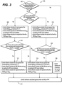
Fig. 3 , there is provided an embodiment of amethod 300 for controlling fuel flow in theaircraft engine 100. Themethod 300 includes determining 302 an energized status of the controlledflow valve fuel feed conduit 122 and determining 304 whether flow in the fuel feed conduit is subsonic or supersonic. Determining 304 if the flow in the feed conduit is subsonic or supersonic includes calculating a ratio of a second fuel pressure (P2) (e.g. from thesignal 157 from the second fuel pressure sensor 156) to a first fuel pressure (P1) (e.g. from thesignal 155 from the first fuel pressure sensor 154). If the ratio of second pressure to first pressure (P2/P1) is less than 0.5283, the fuel flow is considered sonic, while if the ratio is greater than or equal to 0.5283, the fuel flow is considered subsonic. - If the both the first controlled
flow valve 172 and second controlledflow valve 174 are de-energized to prevent flow, the method includes controlling 306 a flow rate through the electronic metering valve to achieve zero pounds per hour fuel flow through theelectronic metering valve 146, i.e. stopping fuel flow through theelectronic metering valve 146. - If only the first controlled
flow valve 172 is energized to allow flow to thefirst fuel manifold 110 and the flow through thefuel feed conduit 122 is supersonic, the method includes calculating 308 a sonic flow rate (Wf /Afmv ) as a function of the first fuel pressure (P1) in thefuel feed conduit 122 upstream of theelectronic metering valve 146 and the fuel temperature (T1) in thefuel feed conduit 122 upstream of theelectronic metering valve 146, where fmv effective area Afmv is a calculated by reading the positionsensor feedback signal 149. Required fuel flow is then calculated using Wf = (Wf /Afmv ) × Afmv. - The
method 300 includes rechecking 310 the energized status of the controlledflow valves fuel feed conduit 122. If both the first and second controlledflow valves fuel feed conduit 122 is still sonic, the method includes recalculating 312 the sonic flow rate, the effective area, and the required fuel flow as described above with respect to 310. The calculated gaseousfuel flow rate 314 is then outputted to thecontroller 144 to control theelectronic metering valve 146 to control flow in thefuel feed conduit 122 and to the first andsecond fuel manifolds recheck 310, either of the first or second controlledflow valves 171, 174 are not energized, or the flow in thefuel feed conduit 122 is now subsonic, themethod 300 includes calculating 316 a subsonic required fuel flow rate as described below and outputting the calculated gaseousfuel flow rate 314 to thecontroller 144. - If after the
initial check 302, both the first and second controlledfuel valves method 300 includes calculating 318 a subsonic flow rate (Wf /Afmv ) as a function of the first fuel pressure (P1) in thefuel feed conduit 122 upstream of theelectronic metering valve 146, the second fuel pressure (P2) in thefuel feed conduit 122 downstream of theelectronic metering valve 146, the delta pressure 161 (e.g. the difference in pressure between the combustor pressure P3 and the second fuel pressure P2), and the first fuel temperature (T1) in thefuel feed conduit 122 upstream of theelectronic metering valve 146, where fmv effective area Afmv is a calculated by reading theposition sensor feedback 149. Required fuel flow is then calculated using Wf = (Wf /Afmv ) × Afmv. - The
method 300 then includes rechecking 320 the energized status of the controlledflow valves fuel feed conduit 122. If either of the first and second controlledflow valves method 300 includes recalculating the subsonic required fuel flow rate as described above with respect to calculating 316. The calculated gaseousfuel flow rate 314 is then outputted to thecontroller 144 to control theelectronic metering valve 146 to control flow in thefuel feed conduit 122 and to the first andsecond fuel manifolds recheck 320 both the first and second controlledflow valves fuel flow rate 314 to thecontroller 144. - The method as described herein can be repeated as many times as needed or desired, or may run continuously while fuel is consumed.
- The embodiments of the present disclosure, as described above and shown in the drawings, provide for improvement in the art to which they pertain. While the apparatus and methods of the subject disclosure have been shown and described, those skilled in the art will readily appreciate that changes and/or modifications may be made thereto without departing from the scope of the subject disclosure as defined by the appended claims.
Claims (15)
- An aircraft engine (100) comprising:a combustor (108); anda fuel control system (200) comprising:a fuel feed conduit (122) including an inlet end (126) and an outlet end (128);a fuel metering mechanism (146) disposed in the fuel feed conduit (122) between the inlet end (126) and the outlet end (128) operable to regulate flow through the fuel feed conduit (122);a position feedback sensor (148) operatively connected to the fuel metering mechanism (146) and operable to generate a signal indicative of a position of the fuel metering mechanism (146);a controller (144) operatively connected to the fuel metering mechanism (146) and to the position feedback sensor (148) and operable to control the position of the fuel metering mechanism (146) based on the signal indicative of the position of the fuel metering mechanism (146) and a command for a desired power output of the aircraft engine (100) to achieve the desired power output;a first fuel pressure sensor (154) operatively connected to the fuel feed conduit (122) and operable to generate a first signal indicative of a fuel pressure in the fuel feed conduit (122), the controller (144) being operatively connected to the first fuel pressure sensor (154) and operable to receive the first signal from the first fuel pressure sensor (154), wherein the controller (144) is operable to control the position of the fuel metering mechanism (146) based on the first signal indicative of the fuel pressure in the fuel feed conduit (122);a second fuel pressure sensor (156) operatively connected to the fuel feed conduit (122) and operable to generate a second signal indicative of a fuel pressure in the fuel feed conduit (122), the controller (144) being operatively connected to the second fuel pressure sensor (156) and operable to receive the second signal from the second fuel pressure sensor (156), wherein the controller (144) is operable to control the position of the fuel metering mechanism (146) based on the second signal indicative of the fuel pressure in the fuel feed conduit (122);a temperature sensor (164) operatively connected to the fuel feed conduit (122) and operable to generate a signal indicative of a fuel temperature in the fuel feed conduit (122), wherein the controller (144) is operable to control the position of the fuel metering mechanism (146) based on the signal indicative of the fuel temperature in the fuel feed conduit (122); anda delta pressure sensor (158) operatively connected to the fuel feed conduit (122) and to the combustor (108), the delta pressure sensor (158) operable to generate a signal (159) indicative of a difference in pressure between the fuel feed conduit (122) and the combustor (108), wherein the controller (144) is operable to control the position of the fuel metering mechanism (146) based on the signal indicative of the difference in pressure between the fuel feed conduit (122) and the combustor (108).
- The aircraft engine (100) as recited in claim 1, wherein the delta pressure sensor (158) operatively connects to the fuel feed conduit (122) via a delta pressure sensor line (161) separate from a second pressure sensor input line (162) of the second fuel pressure sensor (156).
- The aircraft engine (100) as recited in claim 1 or 2, wherein the first fuel pressure sensor (154) is disposed in the fuel feed conduit (122) upstream of the fuel metering mechanism (146), wherein the second pressure sensor (156) is disposed in the fuel feed conduit (122) downstream of the fuel metering mechanism (146) and upstream of the combustor (108), and wherein a third pressure sensor is operatively connected to the delta pressure sensor and operable to communicate a pressure of the combustor (108) to the delta pressure sensor (158).
- The aircraft engine (100) as recited in any preceding claim, wherein each of the first signal indicative of a fuel pressure in the fuel feed conduit (122), the signal indicative of a fuel temperature in the fuel feed conduit (122), the second signal indicative of a fuel pressure in the fuel feed conduit (122), and the signal indicative of the difference in pressure between the fuel feed conduit (122) and the combustor (108) comprise a plurality inputs to a control algorithm executable at least in part by the controller (144) to generate a fuel metering mechanism control signal as an output based on the plurality of inputs, wherein the controller (144) is operable to control the fuel metering mechanism (146) by sending the fuel metering mechanism control signal to the fuel metering mechanism (146).
- The aircraft engine (100) as recited in any preceding claim, further comprising a flow divider assembly (166) fluidly connected to the outlet end (128) of the fuel feed conduit (122) to divide and issue flow from the fuel feed conduit (122) into a first fuel manifold (110) and a second fuel manifold (111), the first and second fuel manifolds (110, 111) being fluidly connected to issue fuel to a respective plurality of fuel nozzles (120).
- The aircraft engine (100) as recited in claim 5, further comprising a first controlled flow valve (172) disposed in the first fuel manifold (110), and a second controlled flow valve (174) disposed in the second fuel manifold (111).
- The aircraft engine (100) as recited in any preceding claim, wherein the fuel metering mechanism (146) is or includes at least one metering valve operable to regulate flow through the fuel feed conduit (122).
- The aircraft engine (100) as recited in any preceding claim, wherein the fuel control system (200) further comprises a torque motor driver (152) operatively connected to drive the fuel metering mechanism (146) upon receipt by the torque motor driver (152) of a command signal from the controller (144) to control the position of the fuel metering mechanism (146).
- The aircraft engine as recited in any preceding claim, wherein the fuel control system (200) further comprises:a gaseous pressure and/or temperature regulated fuel supply (124) fluidly connected to the inlet end (126) of the fuel feed conduit (122);a first plurality of gaseous hydrogen fuel nozzles (120) fluidly connected to the outlet end (128) of the fuel feed conduit (120) via a first fuel manifold (110); anda second plurality of gaseous hydrogen fuel nozzles (120) fluidly connected to the outlet end (128) of the fuel feed conduit (120) via a second fuel manifold (111).
- The aircraft engine (100) as recited in claim 9, further comprising:a compressor section (102) fluidly connected to an inlet of the combustor (108); anda turbine section (116) fluidly connected to an outlet (118) of the combustor (108), wherein the turbine section (116) is operatively connected to the compressor section (102) and operable to drive the compressor section (102);wherein the first and second pluralities of fuel nozzles (120) are fluidly connected to the combustor (108).
- A method for controlling fuel flow in the aircraft engine (100) of any preceding claim, wherein the fuel metering mechanism is an electronic fuel metering valve (146),
the method comprising:determining an energized status of a controlled flow valve in a fuel manifold (110, 111);determining if flow in a fuel feed conduit (122) is sonic;calculating an effective area of the electronic fuel metering valve (146) using a signal indicative of a position of the electronic metering valve (146) from a position feedback sensor;calculating a required fuel flow for a desired power output; andadjusting the position of the electronic fuel metering valve (146) and/or the energized status of the flow valve to achieve the required fuel flow based on the signal indicative of the position of the electronic metering valve (146) and a command for a desired output power to achieve the desired power output. - The method as recited in claim 11, further comprising, if a first controlled flow valve (172) and second controlled flow valve (174) are both de-energized to prevent flow,
controlling a flow rate through the electronic metering valve (146) to achieve zero pounds per hour fuel flow through the electronic metering valve (146). - The method as recited in claim 11 or 12, wherein if the first controlled flow valve (172) is energized to allow flow and the flow through the feed conduit (122) is sonic, then further comprising calculating a sonic flow rate as a function of a first fuel pressure in the fuel feed conduit (122) upstream of the electronic metering valve (146) and a first fuel temperature in the fuel feed conduit (122) upstream of the electronic metering valve (146),
else, if the flow through the feed conduit (122) is sub-sonic, further comprising calculating a subsonic flow rate as a function of the first fuel pressure, the first fuel temperature, a second fuel pressure in the feed conduit (122) downstream of the electronic metering valve (146), and a pressure differential between the second fuel pressure and a pressure in a combustor (108) of the aircraft engine (100). - The method as recited in claim 13, further comprising, after calculating the supersonic flow rate or subsonic flow rate, checking an energized/de-energized status of the first controlled flow valve (172) and of the second controlled flow valve (174) and determining whether the flow through the fuel feed conduit (122) is sonic repeating the steps of calculating a sonic flow rate.
- The method as recited in claim 13 or 14, further comprising calculating a ratio of the second fuel pressure to the first fuel pressure, and determining the flow in the fuel feed conduit (122) is sonic if the ratio is less than 0.5283 and is subsonic if the ratio is greater than or equal to 0.5283.
Applications Claiming Priority (1)
| Application Number | Priority Date | Filing Date | Title |
|---|---|---|---|
| US17/386,399 US20230036266A1 (en) | 2021-07-27 | 2021-07-27 | Controlling gaseous fuel flow |
Publications (2)
| Publication Number | Publication Date |
|---|---|
| EP4124735A1 EP4124735A1 (en) | 2023-02-01 |
| EP4124735B1 true EP4124735B1 (en) | 2025-03-19 |
Family
ID=82748559
Family Applications (1)
| Application Number | Title | Priority Date | Filing Date |
|---|---|---|---|
| EP22187338.3A Active EP4124735B1 (en) | 2021-07-27 | 2022-07-27 | Controlling gaseous fuel flow in an aircraft engine |
Country Status (4)
| Country | Link |
|---|---|
| US (1) | US20230036266A1 (en) |
| EP (1) | EP4124735B1 (en) |
| BR (1) | BR102022014806A2 (en) |
| CA (1) | CA3169133A1 (en) |
Families Citing this family (2)
| Publication number | Priority date | Publication date | Assignee | Title |
|---|---|---|---|---|
| US20240401518A1 (en) * | 2021-10-20 | 2024-12-05 | General Electric Company | Hydrogen fuel system |
| FR3162479A1 (en) * | 2024-05-22 | 2025-11-28 | Safran Aircraft Engines | GAS FUEL FLOW MEASUREMENT COMPENSATION AND IMPROVED TURBOMACHINE REGULATION |
Family Cites Families (17)
| Publication number | Priority date | Publication date | Assignee | Title |
|---|---|---|---|---|
| US6016832A (en) * | 1997-04-16 | 2000-01-25 | Woodward Governor Company | Valve for controlling gas mass flow |
| US6213758B1 (en) * | 1999-11-09 | 2001-04-10 | Megtec Systems, Inc. | Burner air/fuel ratio regulation method and apparatus |
| JP4102564B2 (en) * | 2001-12-28 | 2008-06-18 | 忠弘 大見 | Improved pressure flow controller |
| US6882924B2 (en) * | 2003-05-05 | 2005-04-19 | Precision Engine Controls Corp. | Valve flow control system and method |
| JP4728176B2 (en) * | 2005-06-24 | 2011-07-20 | 株式会社日立製作所 | Burner, gas turbine combustor and burner cooling method |
| JP4831820B2 (en) * | 2006-05-22 | 2011-12-07 | 三菱重工業株式会社 | Gas turbine output learning circuit and gas turbine combustion control apparatus having the same |
| JP4979615B2 (en) * | 2008-03-05 | 2012-07-18 | 株式会社日立製作所 | Combustor and fuel supply method for combustor |
| DE102008032565A1 (en) * | 2008-07-11 | 2010-01-14 | Rolls-Royce Deutschland Ltd & Co Kg | Fuel supply system for a gas turbine engine |
| US8712665B2 (en) * | 2009-11-30 | 2014-04-29 | General Electric Company | Systems and methods for unchoked control of gas turbine fuel gas control valves |
| GB201017166D0 (en) * | 2010-10-12 | 2010-11-24 | Rolls Royce Goodrich Engine Control Systems Ltd | Fuel metering control |
| BR112015015598A2 (en) * | 2012-12-28 | 2017-07-11 | Gen Electric | fluid temperature control and actuation control system and fluid temperature control method |
| US10317082B2 (en) * | 2014-08-12 | 2019-06-11 | Hamilton Sundstrand Corporation | Distributed fuel control system |
| WO2016172083A1 (en) * | 2015-04-20 | 2016-10-27 | Woodward, Inc. | Gas flow fuel metering |
| US10975776B2 (en) * | 2016-04-07 | 2021-04-13 | Raytheon Technologies Corporation | Adaptive fuel flow estimation with flow meter feedback |
| EP4172535A1 (en) * | 2020-06-29 | 2023-05-03 | 8 Rivers Capital, LLC | Systems and methods for control of volumetric flows in a power production plant |
| JP7558092B2 (en) * | 2021-03-12 | 2024-09-30 | 本田技研工業株式会社 | Fuel supply system and fuel supply method |
| US12281721B2 (en) * | 2021-05-17 | 2025-04-22 | Honeywell International Inc. | Metering valve with stepper motor-controlled rotary follow-up servo |
-
2021
- 2021-07-27 US US17/386,399 patent/US20230036266A1/en active Pending
-
2022
- 2022-07-26 CA CA3169133A patent/CA3169133A1/en active Pending
- 2022-07-27 BR BR102022014806-6A patent/BR102022014806A2/en unknown
- 2022-07-27 EP EP22187338.3A patent/EP4124735B1/en active Active
Also Published As
| Publication number | Publication date |
|---|---|
| BR102022014806A2 (en) | 2023-03-07 |
| EP4124735A1 (en) | 2023-02-01 |
| US20230036266A1 (en) | 2023-02-02 |
| CA3169133A1 (en) | 2023-01-27 |
Similar Documents
| Publication | Publication Date | Title |
|---|---|---|
| EP4134530B1 (en) | Pulse width modulation drive for staged fuel manifolds | |
| GB2563660B (en) | Combustion staging system for fuel injectors of a gas turbine engine | |
| EP4063654A2 (en) | Variable displacement pump with active bypass feedback control | |
| US9353688B2 (en) | High pressure, multiple metering zone gas turbine engine fuel supply system | |
| US6675570B2 (en) | Low-cost general aviation fuel control system | |
| US8128378B2 (en) | Dual mode compensation for variable displacement pump fluid metering system | |
| EP2141340B1 (en) | A fuel control arrangement for a gas turbine | |
| EP2138688B1 (en) | A fuel control arrangement | |
| EP4124735B1 (en) | Controlling gaseous fuel flow in an aircraft engine | |
| KR20050056939A (en) | Improved fuel delivery system | |
| EP2025901B1 (en) | Fuel metering system with minimal heat input | |
| US20260008558A1 (en) | Hydrogen fuel delivery system | |
| US11788476B1 (en) | Fluid system with variable pump discharge pressure and method | |
| US10830444B2 (en) | Combustion staging system | |
| EP4130450B1 (en) | Transient gaseous fuel flow scheduling | |
| EP4382747B1 (en) | Variable displacement pump with flow delivery to different systems with different pressure schedules | |
| US12071899B2 (en) | Pump system for a gas turbine engine | |
| US12411503B2 (en) | High turn down ratio direct control for variable displacement pumps with flow sensing | |
| EP2025933B1 (en) | Dual mode compensation for variable displacement pump metering system | |
| US11280342B2 (en) | Rotodynamic pump and method | |
| EP4467797B1 (en) | Direct controlled variable displacement pumps with thermostatically controlled bypass | |
| US12454950B2 (en) | Direct control for variable displacement pumps using a bypass valve and a minimum pressure shutoff valve | |
| EP4467798B1 (en) | Variable displacement metering pumps with direct control |
Legal Events
| Date | Code | Title | Description |
|---|---|---|---|
| PUAI | Public reference made under article 153(3) epc to a published international application that has entered the european phase |
Free format text: ORIGINAL CODE: 0009012 |
|
| STAA | Information on the status of an ep patent application or granted ep patent |
Free format text: STATUS: THE APPLICATION HAS BEEN PUBLISHED |
|
| AK | Designated contracting states |
Kind code of ref document: A1 Designated state(s): AL AT BE BG CH CY CZ DE DK EE ES FI FR GB GR HR HU IE IS IT LI LT LU LV MC MK MT NL NO PL PT RO RS SE SI SK SM TR |
|
| STAA | Information on the status of an ep patent application or granted ep patent |
Free format text: STATUS: REQUEST FOR EXAMINATION WAS MADE |
|
| 17P | Request for examination filed |
Effective date: 20230801 |
|
| RBV | Designated contracting states (corrected) |
Designated state(s): AL AT BE BG CH CY CZ DE DK EE ES FI FR GB GR HR HU IE IS IT LI LT LU LV MC MK MT NL NO PL PT RO RS SE SI SK SM TR |
|
| GRAP | Despatch of communication of intention to grant a patent |
Free format text: ORIGINAL CODE: EPIDOSNIGR1 |
|
| STAA | Information on the status of an ep patent application or granted ep patent |
Free format text: STATUS: GRANT OF PATENT IS INTENDED |
|
| INTG | Intention to grant announced |
Effective date: 20241004 |
|
| GRAS | Grant fee paid |
Free format text: ORIGINAL CODE: EPIDOSNIGR3 |
|
| GRAA | (expected) grant |
Free format text: ORIGINAL CODE: 0009210 |
|
| STAA | Information on the status of an ep patent application or granted ep patent |
Free format text: STATUS: THE PATENT HAS BEEN GRANTED |
|
| AK | Designated contracting states |
Kind code of ref document: B1 Designated state(s): AL AT BE BG CH CY CZ DE DK EE ES FI FR GB GR HR HU IE IS IT LI LT LU LV MC MK MT NL NO PL PT RO RS SE SI SK SM TR |
|
| REG | Reference to a national code |
Ref country code: GB Ref legal event code: FG4D |
|
| REG | Reference to a national code |
Ref country code: CH Ref legal event code: EP |
|
| REG | Reference to a national code |
Ref country code: DE Ref legal event code: R096 Ref document number: 602022011890 Country of ref document: DE |
|
| REG | Reference to a national code |
Ref country code: IE Ref legal event code: FG4D |
|
| PG25 | Lapsed in a contracting state [announced via postgrant information from national office to epo] |
Ref country code: RS Free format text: LAPSE BECAUSE OF FAILURE TO SUBMIT A TRANSLATION OF THE DESCRIPTION OR TO PAY THE FEE WITHIN THE PRESCRIBED TIME-LIMIT Effective date: 20250619 |
|
| PG25 | Lapsed in a contracting state [announced via postgrant information from national office to epo] |
Ref country code: FI Free format text: LAPSE BECAUSE OF FAILURE TO SUBMIT A TRANSLATION OF THE DESCRIPTION OR TO PAY THE FEE WITHIN THE PRESCRIBED TIME-LIMIT Effective date: 20250319 |
|
| REG | Reference to a national code |
Ref country code: LT Ref legal event code: MG9D |
|
| PG25 | Lapsed in a contracting state [announced via postgrant information from national office to epo] |
Ref country code: NO Free format text: LAPSE BECAUSE OF FAILURE TO SUBMIT A TRANSLATION OF THE DESCRIPTION OR TO PAY THE FEE WITHIN THE PRESCRIBED TIME-LIMIT Effective date: 20250619 |
|
| PG25 | Lapsed in a contracting state [announced via postgrant information from national office to epo] |
Ref country code: HR Free format text: LAPSE BECAUSE OF FAILURE TO SUBMIT A TRANSLATION OF THE DESCRIPTION OR TO PAY THE FEE WITHIN THE PRESCRIBED TIME-LIMIT Effective date: 20250319 |
|
| PG25 | Lapsed in a contracting state [announced via postgrant information from national office to epo] |
Ref country code: LV Free format text: LAPSE BECAUSE OF FAILURE TO SUBMIT A TRANSLATION OF THE DESCRIPTION OR TO PAY THE FEE WITHIN THE PRESCRIBED TIME-LIMIT Effective date: 20250319 |
|
| PGFP | Annual fee paid to national office [announced via postgrant information from national office to epo] |
Ref country code: FR Payment date: 20250620 Year of fee payment: 4 |
|
| PG25 | Lapsed in a contracting state [announced via postgrant information from national office to epo] |
Ref country code: GR Free format text: LAPSE BECAUSE OF FAILURE TO SUBMIT A TRANSLATION OF THE DESCRIPTION OR TO PAY THE FEE WITHIN THE PRESCRIBED TIME-LIMIT Effective date: 20250620 Ref country code: BG Free format text: LAPSE BECAUSE OF FAILURE TO SUBMIT A TRANSLATION OF THE DESCRIPTION OR TO PAY THE FEE WITHIN THE PRESCRIBED TIME-LIMIT Effective date: 20250319 |
|
| REG | Reference to a national code |
Ref country code: NL Ref legal event code: MP Effective date: 20250319 |
|
| REG | Reference to a national code |
Ref country code: AT Ref legal event code: MK05 Ref document number: 1777120 Country of ref document: AT Kind code of ref document: T Effective date: 20250319 |
|
| PG25 | Lapsed in a contracting state [announced via postgrant information from national office to epo] |
Ref country code: NL Free format text: LAPSE BECAUSE OF FAILURE TO SUBMIT A TRANSLATION OF THE DESCRIPTION OR TO PAY THE FEE WITHIN THE PRESCRIBED TIME-LIMIT Effective date: 20250319 |
|
| PG25 | Lapsed in a contracting state [announced via postgrant information from national office to epo] |
Ref country code: SE Free format text: LAPSE BECAUSE OF FAILURE TO SUBMIT A TRANSLATION OF THE DESCRIPTION OR TO PAY THE FEE WITHIN THE PRESCRIBED TIME-LIMIT Effective date: 20250319 |
|
| PG25 | Lapsed in a contracting state [announced via postgrant information from national office to epo] |
Ref country code: SM Free format text: LAPSE BECAUSE OF FAILURE TO SUBMIT A TRANSLATION OF THE DESCRIPTION OR TO PAY THE FEE WITHIN THE PRESCRIBED TIME-LIMIT Effective date: 20250319 |
|
| PG25 | Lapsed in a contracting state [announced via postgrant information from national office to epo] |
Ref country code: ES Free format text: LAPSE BECAUSE OF FAILURE TO SUBMIT A TRANSLATION OF THE DESCRIPTION OR TO PAY THE FEE WITHIN THE PRESCRIBED TIME-LIMIT Effective date: 20250319 Ref country code: PT Free format text: LAPSE BECAUSE OF FAILURE TO SUBMIT A TRANSLATION OF THE DESCRIPTION OR TO PAY THE FEE WITHIN THE PRESCRIBED TIME-LIMIT Effective date: 20250721 |
|
| PGFP | Annual fee paid to national office [announced via postgrant information from national office to epo] |
Ref country code: DE Payment date: 20250620 Year of fee payment: 4 |
|
| PG25 | Lapsed in a contracting state [announced via postgrant information from national office to epo] |
Ref country code: PL Free format text: LAPSE BECAUSE OF FAILURE TO SUBMIT A TRANSLATION OF THE DESCRIPTION OR TO PAY THE FEE WITHIN THE PRESCRIBED TIME-LIMIT Effective date: 20250319 |
|
| PGFP | Annual fee paid to national office [announced via postgrant information from national office to epo] |
Ref country code: IT Payment date: 20250731 Year of fee payment: 4 |
|
| PG25 | Lapsed in a contracting state [announced via postgrant information from national office to epo] |
Ref country code: AT Free format text: LAPSE BECAUSE OF FAILURE TO SUBMIT A TRANSLATION OF THE DESCRIPTION OR TO PAY THE FEE WITHIN THE PRESCRIBED TIME-LIMIT Effective date: 20250319 |
|
| PG25 | Lapsed in a contracting state [announced via postgrant information from national office to epo] |
Ref country code: EE Free format text: LAPSE BECAUSE OF FAILURE TO SUBMIT A TRANSLATION OF THE DESCRIPTION OR TO PAY THE FEE WITHIN THE PRESCRIBED TIME-LIMIT Effective date: 20250319 Ref country code: CZ Free format text: LAPSE BECAUSE OF FAILURE TO SUBMIT A TRANSLATION OF THE DESCRIPTION OR TO PAY THE FEE WITHIN THE PRESCRIBED TIME-LIMIT Effective date: 20250319 |
|
| PG25 | Lapsed in a contracting state [announced via postgrant information from national office to epo] |
Ref country code: RO Free format text: LAPSE BECAUSE OF FAILURE TO SUBMIT A TRANSLATION OF THE DESCRIPTION OR TO PAY THE FEE WITHIN THE PRESCRIBED TIME-LIMIT Effective date: 20250319 |
|
| PG25 | Lapsed in a contracting state [announced via postgrant information from national office to epo] |
Ref country code: SK Free format text: LAPSE BECAUSE OF FAILURE TO SUBMIT A TRANSLATION OF THE DESCRIPTION OR TO PAY THE FEE WITHIN THE PRESCRIBED TIME-LIMIT Effective date: 20250319 |
|
| PG25 | Lapsed in a contracting state [announced via postgrant information from national office to epo] |
Ref country code: IS Free format text: LAPSE BECAUSE OF FAILURE TO SUBMIT A TRANSLATION OF THE DESCRIPTION OR TO PAY THE FEE WITHIN THE PRESCRIBED TIME-LIMIT Effective date: 20250719 |
|
| REG | Reference to a national code |
Ref country code: DE Ref legal event code: R097 Ref document number: 602022011890 Country of ref document: DE |
|
| PG25 | Lapsed in a contracting state [announced via postgrant information from national office to epo] |
Ref country code: DK Free format text: LAPSE BECAUSE OF FAILURE TO SUBMIT A TRANSLATION OF THE DESCRIPTION OR TO PAY THE FEE WITHIN THE PRESCRIBED TIME-LIMIT Effective date: 20250319 |
|
| PLBE | No opposition filed within time limit |
Free format text: ORIGINAL CODE: 0009261 |
|
| STAA | Information on the status of an ep patent application or granted ep patent |
Free format text: STATUS: NO OPPOSITION FILED WITHIN TIME LIMIT |
|
| REG | Reference to a national code |
Ref country code: CH Ref legal event code: L10 Free format text: ST27 STATUS EVENT CODE: U-0-0-L10-L00 (AS PROVIDED BY THE NATIONAL OFFICE) Effective date: 20260128 |
|
| REG | Reference to a national code |
Ref country code: CH Ref legal event code: H13 Free format text: ST27 STATUS EVENT CODE: U-0-0-H10-H13 (AS PROVIDED BY THE NATIONAL OFFICE) Effective date: 20260224 |
|
| 26N | No opposition filed |
Effective date: 20251222 |
|
| PG25 | Lapsed in a contracting state [announced via postgrant information from national office to epo] |
Ref country code: LU Free format text: LAPSE BECAUSE OF NON-PAYMENT OF DUE FEES Effective date: 20250727 |
|
| REG | Reference to a national code |
Ref country code: BE Ref legal event code: MM Effective date: 20250731 |
|
| PG25 | Lapsed in a contracting state [announced via postgrant information from national office to epo] |
Ref country code: BE Free format text: LAPSE BECAUSE OF NON-PAYMENT OF DUE FEES Effective date: 20250731 |
|
| PG25 | Lapsed in a contracting state [announced via postgrant information from national office to epo] |
Ref country code: CH Free format text: LAPSE BECAUSE OF NON-PAYMENT OF DUE FEES Effective date: 20250731 |