EP4124574B1 - Multi-engine system and power transfer between engines thereof - Google Patents
Multi-engine system and power transfer between engines thereof Download PDFInfo
- Publication number
- EP4124574B1 EP4124574B1 EP22186942.3A EP22186942A EP4124574B1 EP 4124574 B1 EP4124574 B1 EP 4124574B1 EP 22186942 A EP22186942 A EP 22186942A EP 4124574 B1 EP4124574 B1 EP 4124574B1
- Authority
- EP
- European Patent Office
- Prior art keywords
- engine
- core shaft
- shaft
- gearbox
- power
- Prior art date
- Legal status (The legal status is an assumption and is not a legal conclusion. Google has not performed a legal analysis and makes no representation as to the accuracy of the status listed.)
- Active
Links
Images


Classifications
-
- B—PERFORMING OPERATIONS; TRANSPORTING
- B64—AIRCRAFT; AVIATION; COSMONAUTICS
- B64D—EQUIPMENT FOR FITTING IN OR TO AIRCRAFT; FLIGHT SUITS; PARACHUTES; ARRANGEMENT OR MOUNTING OF POWER PLANTS OR PROPULSION TRANSMISSIONS IN AIRCRAFT
- B64D35/00—Transmitting power from power plants to propellers or rotors; Arrangements of transmissions
- B64D35/02—Transmitting power from power plants to propellers or rotors; Arrangements of transmissions specially adapted for specific power plants
- B64D35/021—Transmitting power from power plants to propellers or rotors; Arrangements of transmissions specially adapted for specific power plants for electric power plants
- B64D35/022—Transmitting power from power plants to propellers or rotors; Arrangements of transmissions specially adapted for specific power plants for electric power plants of hybrid-electric type
- B64D35/024—Transmitting power from power plants to propellers or rotors; Arrangements of transmissions specially adapted for specific power plants for electric power plants of hybrid-electric type of series type
-
- B—PERFORMING OPERATIONS; TRANSPORTING
- B64—AIRCRAFT; AVIATION; COSMONAUTICS
- B64C—AEROPLANES; HELICOPTERS
- B64C27/00—Rotorcraft; Rotors peculiar thereto
- B64C27/04—Helicopters
- B64C27/12—Rotor drives
-
- B—PERFORMING OPERATIONS; TRANSPORTING
- B64—AIRCRAFT; AVIATION; COSMONAUTICS
- B64D—EQUIPMENT FOR FITTING IN OR TO AIRCRAFT; FLIGHT SUITS; PARACHUTES; ARRANGEMENT OR MOUNTING OF POWER PLANTS OR PROPULSION TRANSMISSIONS IN AIRCRAFT
- B64D27/00—Arrangement or mounting of power plants in aircraft; Aircraft characterised by the type or position of power plants
- B64D27/02—Aircraft characterised by the type or position of power plants
- B64D27/10—Aircraft characterised by the type or position of power plants of gas-turbine type
- B64D27/14—Aircraft characterised by the type or position of power plants of gas-turbine type within, or attached to, fuselages
-
- B—PERFORMING OPERATIONS; TRANSPORTING
- B64—AIRCRAFT; AVIATION; COSMONAUTICS
- B64D—EQUIPMENT FOR FITTING IN OR TO AIRCRAFT; FLIGHT SUITS; PARACHUTES; ARRANGEMENT OR MOUNTING OF POWER PLANTS OR PROPULSION TRANSMISSIONS IN AIRCRAFT
- B64D33/00—Arrangement in aircraft of power plant parts or auxiliaries not otherwise provided for
-
- F—MECHANICAL ENGINEERING; LIGHTING; HEATING; WEAPONS; BLASTING
- F01—MACHINES OR ENGINES IN GENERAL; ENGINE PLANTS IN GENERAL; STEAM ENGINES
- F01D—NON-POSITIVE DISPLACEMENT MACHINES OR ENGINES, e.g. STEAM TURBINES
- F01D13/00—Combinations of two or more machines or engines
- F01D13/003—Combinations of two or more machines or engines with at least two independent shafts, i.e. cross-compound
-
- F—MECHANICAL ENGINEERING; LIGHTING; HEATING; WEAPONS; BLASTING
- F01—MACHINES OR ENGINES IN GENERAL; ENGINE PLANTS IN GENERAL; STEAM ENGINES
- F01D—NON-POSITIVE DISPLACEMENT MACHINES OR ENGINES, e.g. STEAM TURBINES
- F01D15/00—Adaptations of machines or engines for special use; Combinations of engines with devices driven thereby
- F01D15/10—Adaptations for driving, or combinations with, electric generators
-
- F—MECHANICAL ENGINEERING; LIGHTING; HEATING; WEAPONS; BLASTING
- F02—COMBUSTION ENGINES; HOT-GAS OR COMBUSTION-PRODUCT ENGINE PLANTS
- F02C—GAS-TURBINE PLANTS; AIR INTAKES FOR JET-PROPULSION PLANTS; CONTROLLING FUEL SUPPLY IN AIR-BREATHING JET-PROPULSION PLANTS
- F02C3/00—Gas-turbine plants characterised by the use of combustion products as the working fluid
- F02C3/04—Gas-turbine plants characterised by the use of combustion products as the working fluid having a turbine driving a compressor
- F02C3/107—Gas-turbine plants characterised by the use of combustion products as the working fluid having a turbine driving a compressor with two or more rotors connected by power transmission
-
- F—MECHANICAL ENGINEERING; LIGHTING; HEATING; WEAPONS; BLASTING
- F02—COMBUSTION ENGINES; HOT-GAS OR COMBUSTION-PRODUCT ENGINE PLANTS
- F02C—GAS-TURBINE PLANTS; AIR INTAKES FOR JET-PROPULSION PLANTS; CONTROLLING FUEL SUPPLY IN AIR-BREATHING JET-PROPULSION PLANTS
- F02C6/00—Plural gas-turbine plants; Combinations of gas-turbine plants with other apparatus; Adaptations of gas-turbine plants for special use
- F02C6/02—Plural gas-turbine plants having a common power output
-
- F—MECHANICAL ENGINEERING; LIGHTING; HEATING; WEAPONS; BLASTING
- F02—COMBUSTION ENGINES; HOT-GAS OR COMBUSTION-PRODUCT ENGINE PLANTS
- F02C—GAS-TURBINE PLANTS; AIR INTAKES FOR JET-PROPULSION PLANTS; CONTROLLING FUEL SUPPLY IN AIR-BREATHING JET-PROPULSION PLANTS
- F02C7/00—Features, components parts, details or accessories, not provided for in, or of interest apart form groups F02C1/00 - F02C6/00; Air intakes for jet-propulsion plants
- F02C7/32—Arrangement, mounting, or driving, of auxiliaries
-
- F—MECHANICAL ENGINEERING; LIGHTING; HEATING; WEAPONS; BLASTING
- F02—COMBUSTION ENGINES; HOT-GAS OR COMBUSTION-PRODUCT ENGINE PLANTS
- F02C—GAS-TURBINE PLANTS; AIR INTAKES FOR JET-PROPULSION PLANTS; CONTROLLING FUEL SUPPLY IN AIR-BREATHING JET-PROPULSION PLANTS
- F02C7/00—Features, components parts, details or accessories, not provided for in, or of interest apart form groups F02C1/00 - F02C6/00; Air intakes for jet-propulsion plants
- F02C7/36—Power transmission arrangements between the different shafts of the gas turbine plant, or between the gas-turbine plant and the power user
-
- B—PERFORMING OPERATIONS; TRANSPORTING
- B64—AIRCRAFT; AVIATION; COSMONAUTICS
- B64C—AEROPLANES; HELICOPTERS
- B64C27/00—Rotorcraft; Rotors peculiar thereto
- B64C27/04—Helicopters
- B64C27/12—Rotor drives
- B64C27/14—Direct drive between power plant and rotor hub
-
- F—MECHANICAL ENGINEERING; LIGHTING; HEATING; WEAPONS; BLASTING
- F05—INDEXING SCHEMES RELATING TO ENGINES OR PUMPS IN VARIOUS SUBCLASSES OF CLASSES F01-F04
- F05D—INDEXING SCHEME FOR ASPECTS RELATING TO NON-POSITIVE-DISPLACEMENT MACHINES OR ENGINES, GAS-TURBINES OR JET-PROPULSION PLANTS
- F05D2220/00—Application
- F05D2220/30—Application in turbines
- F05D2220/32—Application in turbines in gas turbines
- F05D2220/329—Application in turbines in gas turbines in helicopters
-
- F—MECHANICAL ENGINEERING; LIGHTING; HEATING; WEAPONS; BLASTING
- F05—INDEXING SCHEMES RELATING TO ENGINES OR PUMPS IN VARIOUS SUBCLASSES OF CLASSES F01-F04
- F05D—INDEXING SCHEME FOR ASPECTS RELATING TO NON-POSITIVE-DISPLACEMENT MACHINES OR ENGINES, GAS-TURBINES OR JET-PROPULSION PLANTS
- F05D2220/00—Application
- F05D2220/70—Application in combination with
- F05D2220/76—Application in combination with an electrical generator
-
- F—MECHANICAL ENGINEERING; LIGHTING; HEATING; WEAPONS; BLASTING
- F05—INDEXING SCHEMES RELATING TO ENGINES OR PUMPS IN VARIOUS SUBCLASSES OF CLASSES F01-F04
- F05D—INDEXING SCHEME FOR ASPECTS RELATING TO NON-POSITIVE-DISPLACEMENT MACHINES OR ENGINES, GAS-TURBINES OR JET-PROPULSION PLANTS
- F05D2240/00—Components
- F05D2240/60—Shafts
-
- F—MECHANICAL ENGINEERING; LIGHTING; HEATING; WEAPONS; BLASTING
- F05—INDEXING SCHEMES RELATING TO ENGINES OR PUMPS IN VARIOUS SUBCLASSES OF CLASSES F01-F04
- F05D—INDEXING SCHEME FOR ASPECTS RELATING TO NON-POSITIVE-DISPLACEMENT MACHINES OR ENGINES, GAS-TURBINES OR JET-PROPULSION PLANTS
- F05D2260/00—Function
- F05D2260/40—Transmission of power
- F05D2260/402—Transmission of power through friction drives
- F05D2260/4023—Transmission of power through friction drives through a friction clutch
-
- F—MECHANICAL ENGINEERING; LIGHTING; HEATING; WEAPONS; BLASTING
- F05—INDEXING SCHEMES RELATING TO ENGINES OR PUMPS IN VARIOUS SUBCLASSES OF CLASSES F01-F04
- F05D—INDEXING SCHEME FOR ASPECTS RELATING TO NON-POSITIVE-DISPLACEMENT MACHINES OR ENGINES, GAS-TURBINES OR JET-PROPULSION PLANTS
- F05D2260/00—Function
- F05D2260/40—Transmission of power
- F05D2260/403—Transmission of power through the shape of the drive components
- F05D2260/4031—Transmission of power through the shape of the drive components as in toothed gearing
Definitions
- the disclosure relates generally to multi-engine systems for aircrafts and methods of controlling such systems.
- Multi-engine aircrafts such as helicopters are often provided with two or more turboshaft gas turbine engines connected to a main rotor via a common gearbox, and each of the engines is typically capable of providing power greater than what is required for cruising using both/all engines.
- both engines typically operate at similar power output levels (e.g. each engine provides 50% of the total power output).
- Attempts have however been made to operate the engines asymmetrically, that is, operating one engine at a higher power than the other. Doing so can provide overall better fuel efficiency.
- the engine operating at lower power needs to be able to rapidly speed back up, when called upon. While such systems are suitable for their intended purposes, improvements are desirable.
- a prior art multi-engine system for an aircraft having the features of the preamble of claim 1, is disclosed in EP 2963247 A2 . Further prior art multi-engine systems are disclosed in EP 2602458 A1 and US 2015/322864 A1 .
- the multi-engine system defined above and described herein may also include one or more of the following features, in whole or in part, and in any combination.
- the transmission path further comprises an electrical connection between the first electric machine operable as a generator and the second electric machine operable as an electric motor to transmit electrical power generated by the first electric machine to the second electric machine to drive the second core shaft.
- the first electric machine is drivingly engaged by the first core shaft.
- the first set of VGVs 36A upstream of the LP compressor 12 may be mechanically decoupled from the second set of VGVs 36B upstream of the HP compressor 14 and downstream of the LP compressor 12, having no mechanical link between the two sets of VGVs to permit independent operation of the respective stages.
- the VGVs 36 may be operatively controlled by the controller(s) 29 described above, to be operated independently of each other. Indeed, the turboshaft engine 10 is also controlled using controller(s) 29 described above, to carry out the methods described in this document.
- the term "independently" in respects of the VGVs 36 means that the position of one set of the VGV vanes (e.g. 36A) may be set without effecting any change to a position of the other set of the VGV vanes (e.g. 36B), and vice versa.
- Independent control of the VGVs 36 may allow the spools 26, 28 to be operated to reduce or eliminate or reduce aerodynamic coupling between the spools 26, 28. This may permit the spools 26, 28 to be operated at a wider range of speeds than may otherwise be possible.
- the independent control of the VGVs 36 may allow the spools 26, 28 to be operated at constant speed over a wider operating range, such as from a "standby" speed to a "cruise" power speed, or a higher speed.
- independent control of the VGVs 36 may allow the spools 26, 28 to run at speeds close to maximum power.
- independent control of the VGVs 36 may also allow one of the spools 26, 28 to run at high speed while the other one run at low speed.
- the speed of the engine 10 is controlled, at least in part, by the delivery of a desired fuel flow rate (e.g., a rate of change of a fuel flow) to the engine, with a lower fuel flow rate causing the turboshaft engine 10 to operate at a lower output speed than a higher fuel flow rate.
- a desired fuel flow rate e.g., a rate of change of a fuel flow
- the control of the VGVs 36 may provide for improved stability of engine operation. This may be so even where the VGVs 36 is operated at an extreme end of their ranges, such as in the "closed down" position (e.g. at a position of +80 degrees in one embodiment described herein).
- This control of the VGVs 36 may facilitate the ability of the turboshaft engine 10 to operate at a very low power setting, such as may be associated with a "standby" mode as described further below herein, wherein the compressor of an engine operating in standby mode is operating in a very low flow and/or low pressure ratio regime.
- the multi-engine system 42 includes two or more engines 10A, 10B.
- the two engines 10A, 10B drive a common load via a reduction gearbox 46 and an output shaft 60.
- Clutches 61, 62 may be used to selectively engage and disengage output shafts 48, 40A, 40B of the engines 10A, 10B to the reduction gearbox 46.
- these engines 10A, 10B will be turboshaft engines such as the turboshaft engine 10 described above with reference to Fig. 1 . They may alternatively be any suitable gas turbine engines.
- the engines 10A, 10B of the system 42 may be operated asymmetrically, with one engine operated in a high-power "active” mode and the other engine operated in a lower-power "standby” mode. Doing so may provide fuel saving opportunities to the aircraft, however there may be other suitable reasons why the engines are desired to be operated asymmetrically.
- This operation management may therefore be referred to as an "asymmetric mode” or an “asymmetric operating regime", wherein one of the two engines is operated in a low-power "standby mode" while the other engine is operated in a high-power "active” mode.
- the multi-engine system 42 may be used in an aircraft, such as a helicopter , but also has applications in suitable marine and/or industrial applications or other ground operations.
- the multi-engine system 42 driving a helicopter (H) may be operated in this asymmetric manner, in which a first of the turboshaft engines (say, 10A) may be operated at high power in an active mode and the second of the turboshaft engines, for instance the engine 10B in this example, may be operated in a low-power standby mode.
- the first turboshaft engine 10A may be controlled by the controller(s) 29 to run at full (or near-full) power conditions in the active mode, to supply substantially all or all of a required power and/or speed demand of the common load 44.
- an asymmetric operating regime of the engines may be achieved through the one or more controller's 29 differential control of fuel flow to the engines, as described in US 2020/0049025 A1 .
- Low fuel flow may also include zero fuel flow in some examples.
- the controller 29 may operate one engine, for instance the engine 10B, of the multiengine system 42 in a standby mode at a power substantially lower than a rated cruise power level of the engine, and in some embodiments at zero output power and in other embodiments less than 10% output power relative to a reference power (provided at a reference fuel flow).
- the controller(s) 29 may control the standby engine to operate at a power in a range of 0% to 1% of a rated full-power of the standby engine (i.e. the power output of the second engine to the common gearbox remains between 0% to 1% of a rated full-power of the second engine when the second engine is operating in the standby mode).
- asymmetric mode is applicable to more than two engines, whereby at least one of the multiple engines is operated in a low-power standby mode while the remaining engines are operated in the active mode to supply all or substantially all of a required power and/or speed demand of a common load.
- the first turboshaft engine (say 10A) may operate in the active mode while the other turboshaft engine, such as the engine 10B, may operate in the standby mode, as described above.
- the second turboshaft engine 10B may be required to provide more power relative to the low power conditions of the standby mode, and possibly return immediately to a high- or full-power condition. This may occur, for example, in an emergency condition of the multi-engine system 42 powering the helicopter, wherein the "active" engine loses power the power recovery from the lower power to the high power may take some time. Even absent an emergency, it will be desirable to repower the standby engine to exit the asymmetric mode.
- the current disclosure describes systems and methods for coupling the two engines 10A, 10B independently of a reduction gearbox 46 used to drive the main rotor 44. This may provide fuel savings and may reduce recovery time of the low-power engine from the stand-by or low-power mode to the high-power mode.
- the first engine 10A includes a first AGB 50A and a first motor/generator 51A.
- the first motor/generator 51A is drivingly engaged to the HP shaft 34 of the first engine 10A via the first AGB 50A.
- the first motor/generator 51A may alternatively be drivingly engaged to the LP shaft 32 of the first engine 10A via the first AGB 50A.
- the second engine 10B includes a second AGB 50B and a second motor/generator 51B.
- the second motor/generator 51B is drivingly engaged to the HP shaft 34 of the second engine 10B via the second AGB 50B.
- the second motor/generator 51B may alternatively be drivingly engaged to the LP shaft 32 of the second engine 10B via the second AGB 50B.
- each of the engines 10A, 10B has its HP shaft 34 rotating independently from its LP shaft 32.
- the first engine 10A may be operated in a normal or high-power mode whereas the second engine 10B may be operated in idle or a low-power mode. At some point, it may be required to operable both of the engines 10A, 10B in the high-power mode for driving the main rotor 44. This may be required, for instance, if a sudden acceleration is required.
- the multi-engine system 42 shown in Fig. 2 has a transmission path between the first engine 10A and the second engine 10B that is independent from the reduction gearbox 46 that combines rotational inputs of the LP shafts 32 of the two engines 10A, 10B to drive the main rotor 44 or any other common load.
- the transmission path may be used to allow the first engine 10A to transfer energy to the second engine 10B to help accelerating the second engine 10B to operate it in the high-power mode. This may be done by transmitting a torque from the first engine 10A to the second engine 10B and optionally by transmitting electrical power from the first engine 10A to the second engine 10B.
- the transmission path includes a torque-transfer connection between the HP shaft 34 of the second engine 10B and either one of the HP shaft 34 (connection shown with a solid line in Fig. 2 ) of the first engine 10A and the LP shaft 32 (connection shown with a dashed line in Fig. 2 ) of the first engine 10A.
- one or more of the LP shaft 32 and the HP shaft 34 of the first engine 10A may drive the HP shaft 34 of the second engine 10B.
- the torque-transfer connection is therefore a transfer of torque from a shaft of the first engine 10A to the HP shaft 34 of the second engine 10B to spool up rotation of the second engine 10B for faster response time.
- a coupling gearbox 52 is used to drivingly engage the shafts. More detail about this coupling gearbox 52 are provided below.
- the transmission path may additionally include an electrical connection (dashed line) between the first motor/generator 51A of the first engine 10A, which is operated as a generator, to the second motor/generator 51B of the second engine 10B, which is then operated as an electric motor.
- the first and second motor/generator 51A, 51B may be operatively connected to the controller 29, which may calibrate how much power is being transmitted between the first and second motor/generators 51A, 51B to minimize fuel consumption of the second engine 10B when it is being operated in the low-power mode.
- the coupling gearbox 52 includes a first load path P1 and a second load path P2 being independent from one another such that a rotational input may be transmitted from the first input/output 52A to the second input/output 52B solely via the first load path P1 and that a rotational input may be transmitted from the second input/output 52B to the first input/output 52A solely via the second load path P2.
- the first and second load paths P1, P2 are parallel and independent from one another.
- the sixth gear 55F has a greater diameter than the fourth gear 55D and a greater diameter than the fifth gear 55E.
- the second gear 55B is meshed with a seventh gear 55G having a greater diameter than the second gear 55B.
- the seventh gear 55G is coaxial with an eighth gear 55H having a smaller diameter than the seventh gear 55G.
- the eighth gear 55H is meshed with the third gear 55C.
- the eighth gear 55H has a smaller diameter than the third gear 55C.
- the first load path P1 extends from the first gear 55A to the third gear 55C via the second gear 55B, the seventh gear 55G meshed with the second gear 55B, and the eighth gear 55H meshed with the third gear 55C.
- the second load path P2 extends from the third gear 55C to the first gear 55A via the fourth gear 55D, the sixth gear 55F meshed with the fourth gear 55D, and the fifth gear 55E meshed with the first gear 55A.
- the first load path P1 includes a first one-way clutch 56A disposed between the seventh gear 55G and the eighth gear 55h.
- the first one-way clutch 56A allows torque transfer from the first gear 55A to the third gear 55C by permitting a torque transfer from the seventh gear 55G to the eighth gear 55H.
- the first one-way clutch 56A does not allow torque transfer from the third gear 55C to the first gear 55A via the seventh gear 55G and the eighth gear 55H.
- the second load path P2 includes a second one-way clutch 56B disposed between the fifth gear 55E and the sixth gear 55F.
- the second one-way clutch 56B allows torque transfer from the third gear 55C to the first gear 55A by permitting a torque transfer from the sixth gear 55F to the fifth gear 55E.
- the second one-way clutch 56B does not allow torque transfer from the first gear 55A to the third gear 55C via the fifth gear 55E and the sixth gear 55F.
- the one-way clutches may be sprag clutches or any other suitable devices that allow torque transfer in a single direction.
- first one-way clutch 56A may be located between the first input/output 52A and the first gear 55A.
- the second one-way clutch 56B may be located between the second input/output 52B and the third gear 55C.
- the one-way clutches 56A, 56B could be located at gears 55A and 55C instead of gears 55F and 55G. This may allow running the gears 55E, 55F, 55F and 55G at lower speed when the load path is not passing through them.
- These alternate locations of the first and second one-way clutches 56A, 56B are shown in dashed lines in Fig. 4 with reference numerals 56A' and 56B'.
- the coupling gearbox 52 may be considered as a bi-direction de-multiplication gearbox since it may allow the permutation of which of the two engines 10A, 10B is being operated as the high-power engine. This may ensure that both of the engines 10A, 10B wear at a common rate by being either the high or the low power engine alternatively, from flight to flight.
- This coupling gearbox 52 may ensure that the HP shaft 34 of either engine is rotating at a speed at least equal or greater than a given reduction ratio of the speed of the other engine. That reduction ratio is determined based on the required engine recovery time, which may depend of the engine architecture.
- the one-way clutches 56A, 56B may ensure the torque is only able to transfer from the high power engine to the low power engine, when this latter would have tend normally to operate (with the amount of fuel flow provided, or in absence of fuel flow) at a HP shaft speed lower than the high power HP spool time the reduction ratio.
- a fuel flow provided to the low-power engine may be zero.
- the low-power engine may not consume fuel at all when operated in the low-power mode because its HP shaft 34 is driven by the high-power engine.
- the coupling gearbox 52 may be used to create a speed ratio between the HP shafts 34 of the two engines 10A, 10B.
- the first engine 10A which is operated in the high-power mode, may be run at 100% while the second engine 10B operated in the low-power mode may be run at 50% speed. This may allow to even further reduce the amount of fuel required to keep the low power engine running or completely cut the fuel flow and maintain the engine ready for a fast emergency start-up.
- the electrical power fed to the second engine 10B may be used to reduce a fuel consumption of the second engine 10B required to keep the second engine 10B running.
- the fuel flow to the second engine 10B may be cut and the electrical power may be used to maintain a given rotational speed of the HP shaft 34 of the second engine 10B for fast emergency start-up.
- the required amount of electrical energy may be harvested from the first engine 10A, which is operated in the high-power mode, and/or fed into the second engine 10B, and a control system (e.g., controller 29) may be used to stop/start/balance this electrical energy transfer in the manner most likely to reduce fuel consumption for the low power engine and/or limit power penalties for the high power engine.
- a control system e.g., controller 29
- the low-power engine may use a bypass flow path to avoid the air from flowing through the LP compressor 12.
- the VGVs may be used to seal the main gas path to force the air through the bypass flow path.
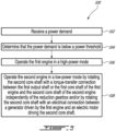
- the method 500 includes receiving a power demand at 502; determining that the power demand is below a power threshold at 504; operating the first engine 10A in a high-power mode at 506; and operating the second engine 10B in a low-power mode by rotating the HP shaft 34 of the second engine 10B with a torque-transfer connection between the LP shaft 32 or the HP shaft 34 of the first engine 10A and the HP shaft 34 of the second engine 10B independently of the reduction gearbox 46 and optionally by rotating the HP shaft 34 of the second engine 10B with an electrical connection between the first motor/generator 51A operated as a generator driven by the first engine 10A and the second motor/generator 51B operated as an electric motor driving the HP shaft 34 of the second engine 10B at 508.
- the HP shaft 34 of the second engine 10B may be rotated at a different rotational speed than the HP shaft 34 of the first engine 10A.
- the clutch 53 may be engaged to drivingly engage the LP or HP shafts 32, 34 of the first engine 10A to the HP shaft 34 of the second engine 10B through the clutch 53.
- the controller 29 may be implemented with one or more computing devices 600.
- the controller 29 can be implemented as part of a full-authority digital engine controls (FADEC) or other similar device, including electronic engine control (EEC), engine control unit (ECU), electronic propeller control, propeller control unit, and the like.
- FADEC full-authority digital engine controls
- EEC electronic engine control
- ECU engine control unit
- propeller control propeller control unit
- the controller 29 is implemented as a Flight Data Acquisition Storage and Transmission system, such as a FAST TM system.
- the controller 29 may be implemented in part in the FAST TM system and in part in the EEC. Other embodiments may also apply.
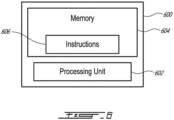
- the computing device 600 comprises a processing unit 602 and a memory 604 which has stored therein computer-executable instructions 606.
- the processing unit 602 may comprise any suitable devices configured to implement the method 500 such that instructions 606, when executed by the computing device 600 or other programmable apparatus, may cause the functions/acts/steps performed as part of the method 500 as described herein to be executed.
- the processing unit 602 may comprise, for example, any type of general-purpose microprocessor or microcontroller, a digital signal processing (DSP) processor, a central processing unit (CPU), an integrated circuit, a field programmable gate array (FPGA), a reconfigurable processor, other suitably programmed or programmable logic circuits, or any combination thereof.
- DSP digital signal processing
- CPU central processing unit
- FPGA field programmable gate array
- reconfigurable processor other suitably programmed or programmable logic circuits, or any combination thereof.
- the memory 604 may comprise any suitable known or other machine-readable storage medium.
- the memory 604 may comprise non-transitory computer readable storage medium, for example, but not limited to, an electronic, magnetic, optical, electromagnetic, infrared, or semiconductor system, apparatus, or device, or any suitable combination of the foregoing.
- the memory 604 may include a suitable combination of any type of computer memory that is located either internally or externally to device, for example random-access memory (RAM), read-only memory (ROM), compact disc read-only memory (CDROM), electro-optical memory, magneto-optical memory, erasable programmable read-only memory (EPROM), and electrically-erasable programmable read-only memory (EEPROM), Ferroelectric RAM (FRAM) or the like.
- Memory 604 may comprise any storage means (e.g., devices) suitable for retrievably storing machine-readable instructions 606 executable by processing unit 602.
- the methods and systems for operating the multi-engine system described herein may be implemented in a high level procedural or object oriented programming or scripting language, or a combination thereof, to communicate with or assist in the operation of a computer system, for example the computing device 600.
- the methods and systems for operating the multi-engine system may be implemented in assembly or machine language.
- the language may be a compiled or interpreted language.
- Program code for implementing the methods and systems for operating the multi-engine system may be stored on a storage media or a device, for example a ROM, a magnetic disk, an optical disc, a flash drive, or any other suitable storage media or device.
- the program code may be readable by a general or special-purpose programmable computer for configuring and operating the computer when the storage media or device is read by the computer to perform the procedures described herein.
- Embodiments of the methods and systems for operating the multi-engine system may also be considered to be implemented by way of a non-transitory computer-readable storage medium having a computer program stored thereon.
- the computer program may comprise computer-readable instructions which cause a computer, or more specifically the processing unit 602 of the computing device 600, to operate in a specific and predefined manner to perform the functions described herein, for example those described in the method 500.
- Computer-executable instructions may be in many forms, including program modules, executed by one or more computers or other devices.
- program modules include routines, programs, objects, components, data structures, etc., that perform particular tasks or implement particular abstract data types.
- functionality of the program modules may be combined or distributed as desired in various embodiments.
- the embodiments described herein are implemented by physical computer hardware, including computing devices, servers, receivers, transmitters, processors, memory, displays, and networks.
- the embodiments described herein provide useful physical machines and particularly configured computer hardware arrangements.
- the embodiments described herein are directed to electronic machines and methods implemented by electronic machines adapted for processing and transforming electromagnetic signals which represent various types of information.
- the embodiments described herein pervasively and integrally relate to machines, and their uses; and the embodiments described herein have no meaning or practical applicability outside their use with computer hardware, machines, and various hardware components. Substituting the physical hardware particularly configured to implement various acts for non-physical hardware, using mental steps for example, may substantially affect the way the embodiments work.
- connection or “coupled to” may include both direct coupling (in which two elements that are coupled to each other contact each other) and indirect coupling (in which at least one additional element is located between the two elements).
Landscapes
- Engineering & Computer Science (AREA)
- Mechanical Engineering (AREA)
- Chemical & Material Sciences (AREA)
- Combustion & Propulsion (AREA)
- General Engineering & Computer Science (AREA)
- Aviation & Aerospace Engineering (AREA)
- Hybrid Electric Vehicles (AREA)
- Supercharger (AREA)
- Output Control And Ontrol Of Special Type Engine (AREA)
Description
- The disclosure relates generally to multi-engine systems for aircrafts and methods of controlling such systems.
- Multi-engine aircrafts such as helicopters are often provided with two or more turboshaft gas turbine engines connected to a main rotor via a common gearbox, and each of the engines is typically capable of providing power greater than what is required for cruising using both/all engines. During normal cruise operating regimes, both engines typically operate at similar power output levels (e.g. each engine provides 50% of the total power output). Attempts have however been made to operate the engines asymmetrically, that is, operating one engine at a higher power than the other. Doing so can provide overall better fuel efficiency. However, the engine operating at lower power needs to be able to rapidly speed back up, when called upon. While such systems are suitable for their intended purposes, improvements are desirable.
- A prior art multi-engine system for an aircraft, having the features of the preamble of
claim 1, is disclosed inEP 2963247 A2 . Further prior art multi-engine systems are disclosed inEP 2602458 A1 andUS 2015/322864 A1 . - In one aspect, there is provided a multi-engine system for an aircraft in accordance with
claim 1. - The multi-engine system defined above and described herein may also include one or more of the following features, in whole or in part, and in any combination.
- In some embodiments, the transmission path further comprises an electrical connection between the first electric machine operable as a generator and the second electric machine operable as an electric motor to transmit electrical power generated by the first electric machine to the second electric machine to drive the second core shaft.
- In some embodiments, the first electric machine is drivingly engaged by the first core shaft.
- In some embodiments, the torque-transfer connection is between the second core shaft and the first core shaft via the coupling gearbox.
- In some embodiments, the first core shaft is drivingly engaged to the first electric machine via a first accessory gearbox, the second core shaft drivingly engaged to the second electric machine via a second accessory gearbox.
- In some embodiments, the torque-transfer connection is between the first accessory gearbox and the second accessory gearbox via the coupling gearbox.
- In some embodiments, the first load path includes a first one-way clutch, the second load path including a second one-way clutch.
- In some embodiments, a clutch is between the second core shaft and the first core shaft or the first output shaft, the clutch operable in engaged and disengaged configurations for respectively selectively engaging or disengaging the torque-transfer connection.
- In another aspect, there is provided a method of operating a multi-engine system in accordance with claim 9.
- The method defined above and described herein may also include one or more of the following features, in whole or in part, and in any combination.
- In some embodiments, the operating the second engine in the low-power mode includes rotating the second core shaft with an electrical connection between a generator driven by the first engine and an electric motor driving the second core shaft.
- In some embodiments, the rotating of the second core shaft with the electrical connection includes drivingly engaging the generator to the first output shaft or the first core shaft via a first accessory gearbox and drivingly engaging the second core shaft with the electric motor via a second accessory gearbox.
- In some embodiments, the rotating of the second core shaft with the torque-transfer connection includes drivingly engaging the first output shaft or the first core shaft to the second core shaft via a first accessory gearbox and via second accessory gearbox drivingly engaged to the first accessory gearbox via the coupling gearbox.
- In some embodiments, the second core shaft is driven at a different rotational speed than the first core shaft.
- In some embodiments, a clutch is engaged from a disengaged configuration to an engaged configuration to drivingly engage the first output shaft or the first core shaft to the second core shaft through the clutch.
- Reference is now made to the accompanying figures in which:
-
Fig. 1 is a schematic cross sectional view of a gas turbine engine depicted as a turboshaft engine; -
Fig. 2 is a schematic representation of an exemplary multi-engine system, showing two of theFig. 1 engines; -
Fig. 3 is a schematic view of a driving engagement between accessory gearboxes of the engines ofFig. 2 ; -
Fig. 4 is an enlarged view of a portion ofFig. 3 illustrating a coupling gearbox; -
Fig. 5 is a flowchart illustrating steps of a method of operating a multi-engine system as shown inFig. 2 ; and -
Fig. 6 is a schematic representation of a computing device in accordance with one embodiment. -
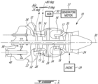
Fig. 1 illustrates a gas turbine engine. In this example, the gas turbine engine is aturboshaft engine 10 generally comprising in serial flow communication a low pressure (LP) compressor section, which will be referred below as theLP compressor 12 and a high pressure (HP) compressor section, which will be referred below as the HPcompressor 14 for pressurizing air received via anair inlet 22. The air compressed by theLP compressor 12 and by the HPcompressor 14 is fed to acombustor 16 in which the compressed air is mixed with a fuel flow, delivered to thecombustor 16 viafuel nozzles 17 from fuel system (not depicted), and ignited for generating a stream of hot combustion gases. A high pressure turbine section, which will referred to below as the HPturbine 18, extracts energy from the combustion gases. A low pressure turbine section, which will be referred to below as theLP turbine 20 is located downstream of the HPturbine 18 for further extracting energy from the combustion gases and driving theLP compressor 12. The combustion gases are then exhausted by anexhaust outlet 24. - In the embodiment shown, the
turboshaft engine 10 includes a low-pressure spool, referred to below asLP spool 26, and a high-pressure spool, referred to below as a HPspool 28. TheLP spool 26 includes a low-pressure shaft, referred to below asLP shaft 32. The HP spool 28 includes a high-pressure shaft, referred to below as HPshaft 34. The HPturbine 18 is drivingly engaged to the HPcompressor 14 via the HPshaft 34. TheLP turbine 20 is drivingly engaged to theLP compressor 12 via theLP shaft 32. The HP spool 28, and the components mounted thereon, are configured to rotate independently from theLP spool 26 and from the components mounted thereon. These two spools may thus rotate at different speeds about an enginecentral axis 30. The HPshaft 34 and theLP shaft 32 may be concentric. In the embodiment shown, the HPshaft 34 extends around theLP shaft 32. The term "spool" is herein intended to broadly refer to drivingly connected turbine and compressor rotors, and need not mean the simple shaft arrangements depicted. - In the embodiment shown, the HP
compressor 14 rotates at the same speed as the HPturbine 18. And, theLP compressor 12 rotates at the same speed as theLP turbine 20. However, this may not be the case if transmission(s) are provided on theLP spool 26 and HP spool 28 to create speed ratios between the interconnected compressors and turbines. This may increase or decrease rotational speeds of the compressors relative to that of the turbines. Any suitable transmissions may be used for this purpose. - The
LP compressor 12 may include one or more compression stages, and the HPcompressor 14 may include one or more compression stages. In the embodiment shown inFig. 1 , theLP compressor 12 includes a single compressor stage 12A (Fig. 2 ), which may include a single mixed flow rotor (MFR), for example such as described inU.S. Patent 6,488,469 B1 , entitled "MIXED FLOW AND CENTRIFUGAL COMPRESSOR FOR GAS TURBINE ENGINE". - The
turboshaft engine 10 may include atransmission 38 driven by thelow pressure shaft 32 and driving arotatable output shaft 40. Thetransmission 38 may optionally be provided to vary a ratio between rotational speeds of thelow pressure shaft 32 and theoutput shaft 40. - The
LP compressor 12 and the HPcompressor 14 are configured to deliver desired respective pressure ratios in use, as will be described further below. TheLP compressor 12 may have a bleed valve 13 (shown schematically) which may be configured to selectively bleed air from theLP compressor 12 according to a desired control regime of theengine 10, for example to assist in control of compressor stability. The design ofsuch valve 13 is well known and not described herein in further detail. Any suitable bleed valve arrangement may be used. - As mentioned, the
HP compressor 14 is configured to independently rotate from theLP compressor 12 by virtue of their mounting on different engine spools. TheHP compressor 14 may include one or more compression stages, such as a single stage, or two ormore stages 14A as shown in more detail inFig. 2 . It is contemplated that theHP compressor 14 may include any suitable type and/or configuration of stages. TheHP compressor 14 is configured to deliver a desired pressure ratio in use, as will be described further below. TheHP compressor 14 may have a bleed valve 15 (shown schematically) which may be configured to selectively bleed air from theHP compressor 14 according to a desired control regime of theengine 10, for example to assist in control of compressor stability. The design ofsuch valve 15 is well known and not described herein in further detail. Any suitable bleed valve arrangement may be used. - In use, suitable one or
more controllers 29, such as one or more full authority digital controllers (FADEC) providing full authority digital control of the various relevant parts of theengine 10, controls operation of theengine 10. The FADEC(s) may be provided as for example conventional software and/or hardware, so long as the FADEC(s) is/are configured to perform the various control methods and sequences as described in this document. Eachcontroller 29 may be used to control one ormore engines 10 of an aircraft (H). Additionally, in some embodiments the controller(s) 29 may be configured for controlling operation of other elements of the aircraft (H), for instance themain rotor 44. - In the embodiment shown, the
turboshaft engine 10 includes an accessory gearbox (AGB) 50 drivingly engaged to an electrical machine, also referred to as a motor/generator 51 via suitable shaft(s) arrangement. TheAGB 50 may be driven by theHP shaft 34 or by theLP shaft 32. In the present embodiment, the motor/generator 51 is drivingly engaged by theHP shaft 34 via theAGB 50. TheAGB 50 may drive other accessories such pumps and so on. - Referring to
Figs. 1-2 , theturboshaft engine 10 may include variable guide vanes (VGVs) 36. In the embodiment shown, a first set ofVGVs 36A is located upstream of theLP compressor 12, and a second set ofVGVs 36B is located upstream of theHP compressor 14. The VGVs 36 may be independently controlled by suitable one ormore controllers 29, as described above. The VGVs 36 may direct inlet air to the corresponding stage of theLP compressor 12 and of theHP compressor 14. The VGVs 36 may be operated to modulate the inlet air flow to the compressors in a manner which may allow for improved control of the output power of theturboshaft engine 10, as described in more detail below. The VGVs 36 may be provided with any suitable operating range. In some embodiments,VGVs 36 may be configured to be positioned and/or modulated between about +80 degrees and about -25 degrees, with 0 degrees being defined as aligned with the inlet air flow, as depicted schematically inFigure 1 . In a more specific embodiment, theVGVs 36 may rotate in a range from +78.5 degrees to - 25 degrees, or from +75 degrees to -20 degrees, and more particularly still from 70 degrees to -20 degrees. The two set ofVGVs 36 may be configured for a similar range of positions, or other suitable position range. - In some embodiments, the first set of
VGVs 36A upstream of theLP compressor 12 may be mechanically decoupled from the second set ofVGVs 36B upstream of theHP compressor 14 and downstream of theLP compressor 12, having no mechanical link between the two sets of VGVs to permit independent operation of the respective stages. The VGVs 36 may be operatively controlled by the controller(s) 29 described above, to be operated independently of each other. Indeed, theturboshaft engine 10 is also controlled using controller(s) 29 described above, to carry out the methods described in this document. For the purposes of this document, the term "independently" in respects of theVGVs 36 means that the position of one set of the VGV vanes (e.g. 36A) may be set without effecting any change to a position of the other set of the VGV vanes (e.g. 36B), and vice versa. - Independent control of the
VGVs 36 may allow thespools spools spools VGVs 36 may allow thespools VGVs 36 may allow thespools VGVs 36 may also allow one of thespools - In use, the
turboshaft engine 10 is operated by the controller(s) 29 described above to introduce a fuel flow via thenozzles 17 to thecombustor 16. Combustion gases turn theHP turbine LP turbine HP compressor LP compressor 12, 12A, 12B. The controller(s) 29 control(s) the angular position of VGVs 36 in accordance with a desired control regime, as will be described further below. The speed of theengine 10 is controlled, at least in part, by the delivery of a desired fuel flow rate (e.g., a rate of change of a fuel flow) to the engine, with a lower fuel flow rate causing theturboshaft engine 10 to operate at a lower output speed than a higher fuel flow rate. - Such control strategies may allow for a faster "power recovery" of the
turboshaft engine 10 such as when an engine is accelerated from a low output speed to a high output speed, possibly because thespools spool control using VGVs 36, as will be further described below. In some embodiments, using theVGVs 36 as described herein, in combination with the use of theLP compressor 12, which may be MFR based, and of theHP compressor 14, which may be MFR based, may provide relatively more air and/or flow control authority and range through the core of theengine 10, and/or quicker power recovery. - Where MFR compressors of the
turboshaft engine 10 are provided as described herein, the control of theVGVs 36 may provide for improved stability of engine operation. This may be so even where theVGVs 36 is operated at an extreme end of their ranges, such as in the "closed down" position (e.g. at a position of +80 degrees in one embodiment described herein). This control of theVGVs 36 may facilitate the ability of theturboshaft engine 10 to operate at a very low power setting, such as may be associated with a "standby" mode as described further below herein, wherein the compressor of an engine operating in standby mode is operating in a very low flow and/or low pressure ratio regime. - Turning now to
Fig. 2 , illustrated is an exemplary multi-engine system 42 that may be used as a power plant for an aircraft, including but not limited to a rotorcraft such as a helicopter (H). The multi-engine system 42 includes two ormore engines engines reduction gearbox 46 and anoutput shaft 60.Clutches output shafts engines reduction gearbox 46. In the case of a helicopter application, theseengines turboshaft engine 10 described above with reference toFig. 1 . They may alternatively be any suitable gas turbine engines. Control of the multi-engine system 42 is effected by one or more controller(s) 29, which may be FADEC(s), electronic engine controller(s) (EEC(s)), or the like, that are programmed to manage, as described herein below, the operation of theengines - In the present description, while the aircraft conditions, such as cruise speed and altitude, are substantially stable, the
engines - Referring still to
Fig. 2 , according to the present description the multi-engine system 42 driving a helicopter (H) may be operated in this asymmetric manner, in which a first of the turboshaft engines (say, 10A) may be operated at high power in an active mode and the second of the turboshaft engines, for instance theengine 10B in this example, may be operated in a low-power standby mode. In one example, thefirst turboshaft engine 10A may be controlled by the controller(s) 29 to run at full (or near-full) power conditions in the active mode, to supply substantially all or all of a required power and/or speed demand of thecommon load 44. Thesecond turboshaft engine 10B may be controlled by the controller(s) 29 to operate at low-power or no-output-power conditions to supply substantially none or none of a required power and/or speed demand of thecommon load 44. Optionally, a clutch may be provided to declutch the low-power engine. Controller(s) 29 may control the engine's governing on power according to an appropriate schedule or control regime. The controller(s) 29 may comprise a first controller for controlling thefirst engine 10A and a second controller for controlling thesecond engine 10B. The first controller and the second controller may be in communication with each other in order to implement the operations described herein. In some embodiments, asingle controller 29 may be used for controlling thefirst engine 10A and thesecond engine 10B. The term controller as used herein includes any one of: a single controller controlling the engines, and any suitable combination of multiple controllers controlling the engines, including one or more controllers for each engine, so long as the functionality described in this document is provided. - In another example, an asymmetric operating regime of the engines may be achieved through the one or more controller's 29 differential control of fuel flow to the engines, as described in
US 2020/0049025 A1 . Low fuel flow may also include zero fuel flow in some examples. - Although various differential control between the engines of the engine system 42 are possible, in one particular embodiment the controller(s)29 may correspondingly control fuel flow rate to each
engine method 60, the fuel flow rate difference between the active and standby engines may be controlled to be in a range of 70% and 90% of each other, with fuel flow to the standby engine being 70% to 90% less than the active engine. In some embodiments, the fuel flow rate difference may be controlled to be in a range of 80% and 90%, with fuel flow to the standby engine being 80% to 90% less than the active engine. - In another embodiment, the
controller 29 may operate one engine, for instance theengine 10B, of the multiengine system 42 in a standby mode at a power substantially lower than a rated cruise power level of the engine, and in some embodiments at zero output power and in other embodiments less than 10% output power relative to a reference power (provided at a reference fuel flow). Alternately still, in some embodiments, the controller(s) 29 may control the standby engine to operate at a power in a range of 0% to 1% of a rated full-power of the standby engine (i.e. the power output of the second engine to the common gearbox remains between 0% to 1% of a rated full-power of the second engine when the second engine is operating in the standby mode). - In another example, the engine system 42 of
Fig. 2 may be operated in an asymmetric operating regime by control of the relative speed of the engines using controller(s) 29, that is, the standby engine is controlled to a target low speed and the active engine is controlled to a target high speed. Such a low speed operation of the standby engine may include, for example, a rotational speed that is less than a typical ground idle speed of the engine (i.e. a "sub-idle" engine speed). Still other control regimes may be available for operating the engines in the asymmetric operating regime, such as control based on a target pressure ratio, or other suitable control parameters. - Although the examples described herein illustrate two engines, asymmetric mode is applicable to more than two engines, whereby at least one of the multiple engines is operated in a low-power standby mode while the remaining engines are operated in the active mode to supply all or substantially all of a required power and/or speed demand of a common load.
- In use, the first turboshaft engine (say 10A) may operate in the active mode while the other turboshaft engine, such as the
engine 10B, may operate in the standby mode, as described above. During this asymmetric operation, if the helicopter (H) needs a power increase (expected or otherwise), thesecond turboshaft engine 10B may be required to provide more power relative to the low power conditions of the standby mode, and possibly return immediately to a high- or full-power condition. This may occur, for example, in an emergency condition of the multi-engine system 42 powering the helicopter, wherein the "active" engine loses power the power recovery from the lower power to the high power may take some time. Even absent an emergency, it will be desirable to repower the standby engine to exit the asymmetric mode. - However, maintaining the low-power engine in a stand-by mode requires fuel since combustion is maintained in its combustion chamber. The current disclosure describes systems and methods for coupling the two
engines reduction gearbox 46 used to drive themain rotor 44. This may provide fuel savings and may reduce recovery time of the low-power engine from the stand-by or low-power mode to the high-power mode. - Still referring to
Fig. 2 , in the embodiment shown, thefirst engine 10A includes afirst AGB 50A and a first motor/generator 51A. The first motor/generator 51A is drivingly engaged to theHP shaft 34 of thefirst engine 10A via thefirst AGB 50A. The first motor/generator 51A may alternatively be drivingly engaged to theLP shaft 32 of thefirst engine 10A via thefirst AGB 50A. Similarly, thesecond engine 10B includes asecond AGB 50B and a second motor/generator 51B. The second motor/generator 51B is drivingly engaged to theHP shaft 34 of thesecond engine 10B via thesecond AGB 50B. In examples not presently being claimed, the second motor/generator 51B may alternatively be drivingly engaged to theLP shaft 32 of thesecond engine 10B via thesecond AGB 50B. As mentioned above, each of theengines HP shaft 34 rotating independently from itsLP shaft 32. - In some cases, the
first engine 10A may be operated in a normal or high-power mode whereas thesecond engine 10B may be operated in idle or a low-power mode. At some point, it may be required to operable both of theengines main rotor 44. This may be required, for instance, if a sudden acceleration is required. - Referring to
Figs. 2-3 , the multi-engine system 42 shown inFig. 2 has a transmission path between thefirst engine 10A and thesecond engine 10B that is independent from thereduction gearbox 46 that combines rotational inputs of theLP shafts 32 of the twoengines main rotor 44 or any other common load. In the present embodiment, the transmission path may be used to allow thefirst engine 10A to transfer energy to thesecond engine 10B to help accelerating thesecond engine 10B to operate it in the high-power mode. This may be done by transmitting a torque from thefirst engine 10A to thesecond engine 10B and optionally by transmitting electrical power from thefirst engine 10A to thesecond engine 10B. - More specifically, the transmission path includes a torque-transfer connection between the
HP shaft 34 of thesecond engine 10B and either one of the HP shaft 34 (connection shown with a solid line inFig. 2 ) of thefirst engine 10A and the LP shaft 32 (connection shown with a dashed line inFig. 2 ) of thefirst engine 10A. In some cases, one or more of theLP shaft 32 and theHP shaft 34 of thefirst engine 10A may drive theHP shaft 34 of thesecond engine 10B. The torque-transfer connection is therefore a transfer of torque from a shaft of thefirst engine 10A to theHP shaft 34 of thesecond engine 10B to spool up rotation of thesecond engine 10B for faster response time. Acoupling gearbox 52 is used to drivingly engage the shafts. More detail about thiscoupling gearbox 52 are provided below. - The transmission path may additionally include an electrical connection (dashed line) between the first motor/
generator 51A of thefirst engine 10A, which is operated as a generator, to the second motor/generator 51B of thesecond engine 10B, which is then operated as an electric motor. The first and second motor/generator controller 29, which may calibrate how much power is being transmitted between the first and second motor/generators second engine 10B when it is being operated in the low-power mode. Hence, to drive the low-power engine, the high-power engine may drive the first motor/generator 51A in a generator mode and
the electrical power generated by the first motor/generator 51A driven by the high-power engine may power the second motor/generator 51B in a motor mode. The second motor/generator 51B may therefore drive theHP shaft 34 of the low-power engine. - Still referring to
Fig. 2 , in the depicted embodiment, the torque-transfer connection is created between theHP shaft 34 of thefirst engine 10A and theHP shaft 34 of thesecond engine 10B via thecoupling gearbox 52. TheHP shaft 34 of thefirst engine 10A may be drivingly engaged to thecoupling gearbox 52 via thefirst AGB 50A. Similarly, theHP shaft 34 of thesecond engine 10B may be drivingly engaged to thecoupling gearbox 52 via thesecond AGB 50B. Hence, the torque-transfer connection may be between thefirst AGB 50A and thesecond AGB 50B via thecoupling gearbox 52. Therefore, torque generated by the HP shaft 34 (and/or the LP shaft 32) of thefirst engine 10A is transmitted to theHP shaft 34 of thesecond engine 10B via thefirst AGB 50A, thecoupling gearbox 52, and thesecond AGB 50B. - Referring more particularly to
Fig. 3 , in the embodiment shown, a clutch 53 is disposed between theHP shaft 34 of thesecond engine 10B and the LP orHP shaft first engine 10A. The clutch 53 is operable in engaged and disengaged configurations for respectively selectively engaging or disengaging the torque-transfer connection. The clutch 53 may be more specifically located between thefirst AGB 50A and thecoupling gearbox 52 on ashaft 54 that drivingly engages thefirst AGB 50A to thecoupling gearbox 52. Any other suitable locations for the clutch 53 are contemplated without departing from the scope of the present disclosure. The clutch 53 may be disengaged when it is not necessary to couple the twoengines HP shaft 34 of the engine that is starting. - Referring more particularly to
Fig. 4 , thecoupling gearbox 52 may allow to interchangeably use either one of the first andsecond engines engines - The
coupling gearbox 52 has a first input/output 52A that is drivingly engaged to thefirst engine 10A and a second input/output 52B that drivingly engaged to thesecond engine 10B. In the present embodiment, the first input/output 52A is drivingly engaged to thefirst AGB 50A and the second input/output 52B is drivingly engaged to thesecond AGB 50B. - In use, a speed ratio provided by the
coupling gearbox 52 from the first input/output 52A to the second input/output 52B is the same as a speed ratio provided by thecoupling gearbox 52 from the second input/output 52B to the first input/output 52A. This may ensure that a speed ratio between the engine being operated in the high-power mode and the engine being operated in low-power mode remains the same whether thefirst engine 10A or thesecond engine 10B is being operated in the high-power mode. The reduction in the rotational speed of the engine being operated in low-power mode may be desirable at the low power engine for energy economy reason. Maintaining a stand-by engine ready for fast start-up or fast ramp-up may require less energy as the internal component of the engine rotate at lower speed for an air mass flow lower or equal. Moreover, thermal efficiency of the engine may be less when operated in the low-power mode than in the high-power mode. Hence, the low-power engine may require more fuel flow to rotate theHP shaft 34 of the low-power engine at a low speed than would the high-power engine to rotate theHP shaft 34 of the low-power engine at the same low speed. Hence, using the high-power engine to rotate theHP shaft 34 of the low-power engine may be beneficial for the overall fuel efficiency of an aircraft requiring the low-power engine to be maintained in a operating mode that allow fast re-start or ramp-up in case of emergency power demand. - To this end, the
coupling gearbox 52 includes a first load path P1 and a second load path P2 being independent from one another such that a rotational input may be transmitted from the first input/output 52A to the second input/output 52B solely via the first load path P1 and that a rotational input may be transmitted from the second input/output 52B to the first input/output 52A solely via the second load path P2. The first and second load paths P1, P2 are parallel and independent from one another. Thecoupling gearbox 52 may therefore be reversible such that theHP shaft 34 of thefirst engine 10A is driving theHP shaft 34 of thesecond engine 10B via the first load path P1 and theHP shaft 34 of thesecond engine 10B is driving theHP shaft 34 of thefirst engine 10A via the second load path P2. - In the depicted embodiment, the
coupling gearbox 52 includes gears, namely afirst gear 55A driving asecond gear 55B being coaxial with thefirst gear 55A and having a smaller diameter than thefirst gear 55A. Thefirst gear 55A is driven by theHP shaft 34 of thefirst engine 10A. The gears include athird gear 55C driving afourth gear 55D being coaxial with thethird gear 55C and having a smaller diameter than thethird gear 55C. Thethird gear 55C is driving theHP shaft 34 of thesecond engine 10B. Thefirst gear 55A is meshed with afifth gear 55E having a smaller diameter than thefirst gear 55A. Thefifth gear 55E is coaxial with asixth gear 55F meshed with thefourth gear 55D. Thesixth gear 55F has a greater diameter than thefourth gear 55D and a greater diameter than thefifth gear 55E. Thesecond gear 55B is meshed with aseventh gear 55G having a greater diameter than thesecond gear 55B. Theseventh gear 55G is coaxial with aneighth gear 55H having a smaller diameter than theseventh gear 55G. Theeighth gear 55H is meshed with thethird gear 55C. Theeighth gear 55H has a smaller diameter than thethird gear 55C. - The first load path P1 extends from the
first gear 55A to thethird gear 55C via thesecond gear 55B, theseventh gear 55G meshed with thesecond gear 55B, and theeighth gear 55H meshed with thethird gear 55C. The second load path P2 extends from thethird gear 55C to thefirst gear 55A via thefourth gear 55D, thesixth gear 55F meshed with thefourth gear 55D, and thefifth gear 55E meshed with thefirst gear 55A. The first load path P1 includes a first one-way clutch 56A disposed between theseventh gear 55G and the eighth gear 55h. The first one-way clutch 56A allows torque transfer from thefirst gear 55A to thethird gear 55C by permitting a torque transfer from theseventh gear 55G to theeighth gear 55H. The first one-way clutch 56A does not allow torque transfer from thethird gear 55C to thefirst gear 55A via theseventh gear 55G and theeighth gear 55H. The second load path P2 includes a second one-way clutch 56B disposed between thefifth gear 55E and thesixth gear 55F. The second one-way clutch 56B allows torque transfer from thethird gear 55C to thefirst gear 55A by permitting a torque transfer from thesixth gear 55F to thefifth gear 55E. The second one-way clutch 56B does not allow torque transfer from thefirst gear 55A to thethird gear 55C via thefifth gear 55E and thesixth gear 55F. The one-way clutches may be sprag clutches or any other suitable devices that allow torque transfer in a single direction. It will be appreciated that any other suitable gearing arrangements may be used without departing from the scope of the present disclosure. However, any other suitable locations of these one-way clutches are contemplated without departing from the scope of the present disclosure. These one-way clutches may ensure that the two load paths P1, P2 do not work against one another. The two one-way freewheel clutches - In an alternate embodiment, the first one-way clutch 56A may be located between the first input/
output 52A and thefirst gear 55A. The second one-way clutch 56B may be located between the second input/output 52B and thethird gear 55C. In other words, the one-way clutches gears gears gears way clutches Fig. 4 withreference numerals 56A' and 56B'. - The
coupling gearbox 52 may be considered as a bi-direction de-multiplication gearbox since it may allow the permutation of which of the twoengines engines coupling gearbox 52 may ensure that theHP shaft 34 of either engine is rotating at a speed at least equal or greater than a given reduction ratio of the speed of the other engine. That reduction ratio is determined based on the required engine recovery time, which may depend of the engine architecture. The one-way clutches HP shaft 34 is driven by the high-power engine. - The
coupling gearbox 52 may be used to create a speed ratio between theHP shafts 34 of the twoengines first engine 10A, which is operated in the high-power mode, may be run at 100% while thesecond engine 10B operated in the low-power mode may be run at 50% speed. This may allow to even further reduce the amount of fuel required to keep the low power engine running or completely cut the fuel flow and maintain the engine ready for a fast emergency start-up. - In some embodiments, the electrical power fed to the
second engine 10B, which is operated in the low-power mode, may be used to reduce a fuel consumption of thesecond engine 10B required to keep thesecond engine 10B running. In some cases, the fuel flow to thesecond engine 10B may be cut and the electrical power may be used to maintain a given rotational speed of theHP shaft 34 of thesecond engine 10B for fast emergency start-up. - Because the electrical signal may be modulated as required, the required amount of electrical energy may be harvested from the
first engine 10A, which is operated in the high-power mode, and/or fed into thesecond engine 10B, and a control system (e.g., controller 29) may be used to stop/start/balance this electrical energy transfer in the manner most likely to reduce fuel consumption for the low power engine and/or limit power penalties for the high power engine. - In some embodiments, the low-power engine may use a bypass flow path to avoid the air from flowing through the
LP compressor 12. The VGVs may be used to seal the main gas path to force the air through the bypass flow path. - Referring now to
Fig. 5 , a method of operating the multi-engine system 42 is shown at 500. Themethod 500 includes receiving a power demand at 502; determining that the power demand is below a power threshold at 504; operating thefirst engine 10A in a high-power mode at 506; and operating thesecond engine 10B in a low-power mode by rotating theHP shaft 34 of thesecond engine 10B with a torque-transfer connection between theLP shaft 32 or theHP shaft 34 of thefirst engine 10A and theHP shaft 34 of thesecond engine 10B independently of thereduction gearbox 46 and optionally by rotating theHP shaft 34 of thesecond engine 10B with an electrical connection between the first motor/generator 51A operated as a generator driven by thefirst engine 10A and the second motor/generator 51B operated as an electric motor driving theHP shaft 34 of thesecond engine 10B at 508. - In the embodiment shown, the operating the
second engine 10B in the low-power mode includes the rotating of theHP shaft 34 of thesecond engine 10B with the torque-transfer connection and with the electrical connection. The rotating of theHP shaft 34 of thesecond engine 10B with the electrical connection may include drivingly engaging thegenerator 51A to theLP shaft 32 of thefirst engine 10A or theHP shaft 34 of thefirst engine 10A via thefirst AGB 50A and drivingly engaging theHP shaft 34 of thesecond engine 10B with theelectric motor 51B via thesecond AGB 51B. - In the embodiment shown, the rotating of the
HP shaft 34 of thesecond engine 10B with the torque-transfer connection includes drivingly engaging the LP orHP shafts first engine 10A to theHP shaft 34 of thesecond engine 10B via thefirst AGB 50A and via thesecond AGB 50B drivingly engaged to thefirst AGB 50A via thecoupling gearbox 52. - In some cases, the
HP shaft 34 of thesecond engine 10B may be rotated at a different rotational speed than theHP shaft 34 of thefirst engine 10A. The clutch 53 may be engaged to drivingly engage the LP orHP shafts first engine 10A to theHP shaft 34 of thesecond engine 10B through the clutch 53. - With reference to
Fig. 6 , an example of acomputing device 600 is illustrated. For simplicity only onecomputing device 600 is shown but the system may includemore computing devices 600 operable to exchange data. Thecomputing devices 600 may be the same or different types of devices. Thecontroller 29 may be implemented with one ormore computing devices 600. Note that thecontroller 29 can be implemented as part of a full-authority digital engine controls (FADEC) or other similar device, including electronic engine control (EEC), engine control unit (ECU), electronic propeller control, propeller control unit, and the like. In some embodiments, thecontroller 29 is implemented as a Flight Data Acquisition Storage and Transmission system, such as a FAST™ system. Thecontroller 29 may be implemented in part in the FAST™ system and in part in the EEC. Other embodiments may also apply. - The
computing device 600 comprises aprocessing unit 602 and amemory 604 which has stored therein computer-executable instructions 606. Theprocessing unit 602 may comprise any suitable devices configured to implement themethod 500 such thatinstructions 606, when executed by thecomputing device 600 or other programmable apparatus, may cause the functions/acts/steps performed as part of themethod 500 as described herein to be executed. Theprocessing unit 602 may comprise, for example, any type of general-purpose microprocessor or microcontroller, a digital signal processing (DSP) processor, a central processing unit (CPU), an integrated circuit, a field programmable gate array (FPGA), a reconfigurable processor, other suitably programmed or programmable logic circuits, or any combination thereof. - The
memory 604 may comprise any suitable known or other machine-readable storage medium. Thememory 604 may comprise non-transitory computer readable storage medium, for example, but not limited to, an electronic, magnetic, optical, electromagnetic, infrared, or semiconductor system, apparatus, or device, or any suitable combination of the foregoing. Thememory 604 may include a suitable combination of any type of computer memory that is located either internally or externally to device, for example random-access memory (RAM), read-only memory (ROM), compact disc read-only memory (CDROM), electro-optical memory, magneto-optical memory, erasable programmable read-only memory (EPROM), and electrically-erasable programmable read-only memory (EEPROM), Ferroelectric RAM (FRAM) or the like.Memory 604 may comprise any storage means (e.g., devices) suitable for retrievably storing machine-readable instructions 606 executable by processingunit 602. - The methods and systems for operating the multi-engine system described herein may be implemented in a high level procedural or object oriented programming or scripting language, or a combination thereof, to communicate with or assist in the operation of a computer system, for example the
computing device 600. Alternatively, the methods and systems for operating the multi-engine system may be implemented in assembly or machine language. The language may be a compiled or interpreted language. Program code for implementing the methods and systems for operating the multi-engine system may be stored on a storage media or a device, for example a ROM, a magnetic disk, an optical disc, a flash drive, or any other suitable storage media or device. The program code may be readable by a general or special-purpose programmable computer for configuring and operating the computer when the storage media or device is read by the computer to perform the procedures described herein. Embodiments of the methods and systems for operating the multi-engine system may also be considered to be implemented by way of a non-transitory computer-readable storage medium having a computer program stored thereon. The computer program may comprise computer-readable instructions which cause a computer, or more specifically theprocessing unit 602 of thecomputing device 600, to operate in a specific and predefined manner to perform the functions described herein, for example those described in themethod 500. - Computer-executable instructions may be in many forms, including program modules, executed by one or more computers or other devices. Generally, program modules include routines, programs, objects, components, data structures, etc., that perform particular tasks or implement particular abstract data types. Typically the functionality of the program modules may be combined or distributed as desired in various embodiments.
- The embodiments described herein are implemented by physical computer hardware, including computing devices, servers, receivers, transmitters, processors, memory, displays, and networks. The embodiments described herein provide useful physical machines and particularly configured computer hardware arrangements. The embodiments described herein are directed to electronic machines and methods implemented by electronic machines adapted for processing and transforming electromagnetic signals which represent various types of information. The embodiments described herein pervasively and integrally relate to machines, and their uses; and the embodiments described herein have no meaning or practical applicability outside their use with computer hardware, machines, and various hardware components. Substituting the physical hardware particularly configured to implement various acts for non-physical hardware, using mental steps for example, may substantially affect the way the embodiments work. Such computer hardware limitations are clearly essential elements of the embodiments described herein, and they cannot be omitted or substituted for mental means without having a material effect on the operation and structure of the embodiments described herein. The computer hardware is essential to implement the various embodiments described herein and is not merely used to perform steps expeditiously and in an efficient manner.
- The term "connected" or "coupled to" may include both direct coupling (in which two elements that are coupled to each other contact each other) and indirect coupling (in which at least one additional element is located between the two elements).
- The technical solution of embodiments may be in the form of a software product. The software product may be stored in a non-volatile or non-transitory storage medium, which can be a compact disk read-only memory (CD-ROM), a USB flash disk, or a removable hard disk. The software product includes a number of instructions that enable a computer device (personal computer, server, or network device) to execute the methods provided by the embodiments.
- The embodiments described in this document provide non-limiting examples of possible implementations of the present technology. Upon review of the present disclosure, a person of ordinary skill in the art will recognize that changes may be made to the embodiments described herein without departing from the scope of the appended claims. Yet further modifications could be implemented by a person of ordinary skill in the art in view of the present disclosure, which modifications would be within the scope of the present technology insofar as they fall within the scope of the appended claims.
Claims (14)
- A multi-engine system (42) for an aircraft, comprising:a first engine (10A) having a first output shaft (32) and a first core shaft (34));a second engine (10) having a second output shaft (32) and a second core shaft (34);a reduction gearbox (46) drivingly engaged by the first output shaft (32) and by the second output shaft (32) for driving a common load (44); anda transmission path between the first engine (10A) and the second engine (10B), the transmission path being independent from the reduction gearbox (48), the transmission path being a torque-transfer connection between the second core shaft (34) and the first core shaft (34) or the first output shaft (32) via a coupling gearbox (52),characterised in that:the first engine (10A) has a first electric machine (51A) operable as a generator, the first electric machine (51A) drivingly engaged by the first output shaft (32) or the first core shaft (34);the second engine (10) has a second electric machine (51B) operable as an electric motor, the second electric machine (51B) drivingly engaged to the second core shaft (34); andthe coupling gearbox (52) has a first load path (P1) and a second load path (P2), the second load path (P2) independent from the first load path (P1), the coupling gearbox (52) being reversible such that the first core shaft (34) and/or the first output shaft (32) is driving the second core shaft (34) via the first load path (P1) and the second core shaft (34) is driving the first core shaft (34) via the second load path (P2).
- The multi-engine system of claim 1, wherein the transmission path further comprises an electrical connection between the first electric machine (51A) operable as a generator and the second electric machine (51B) operable as an electric motor to transmit electrical power generated by the first electric machine (51A) to the second electric machine (51B) to drive the second core shaft (34).
- The multi-engine system of claim 1 or 2, wherein the first electric machine (51A) is drivingly engaged by the first core shaft (34).
- The multi-engine system of any preceding claim, wherein the torque-transfer connection is between the second core shaft (34) and the first core shaft (34) via the coupling gearbox (52).
- The multi-engine system of any preceding claim, wherein the first core shaft (34) is drivingly engaged to the first electric machine (51A) via a first accessory gearbox (50A), the second core shaft (34) drivingly engaged to the second electric machine (51B) via a second accessory gearbox (50B).
- The multi-engine system of claim 5, wherein the torque-transfer connection is between the first accessory gearbox (50A) and the second accessory gearbox (50B) via the coupling gearbox (52).
- The multi-engine system of any preceding claim, wherein the first load path (P1) includes a first one-way clutch (56A) and the second load path (P2) includes a second one-way clutch (56B).
- The multi-engine system of any preceding claim, comprising a clutch (53) between the second core shaft (34) and the first core shaft (34) or the first output shaft (32), the clutch (53) operable in engaged and disengaged configurations for respectively selectively engaging or disengaging the torque-transfer connection.
- A method of operating a multi-engine system (42) for an aircraft, having a first engine (10A) and a second engine (10B), the first engine (10A) having a first output shaft (32) and a first core shaft (34), the second engine (10B) having a second output shaft (32) and a second core shaft (34), the first output shaft (32) and the second output shaft (32) drivingly engaged to a common load (44) via a reduction gearbox (46), the method comprising:receiving a power demand;determining that the power demand is below a power threshold;operating the first engine (10A) in a high-power mode; andoperating the second engine (10B) in a low-power mode by rotating the second core shaft (34) with a torque-transfer connection between the first output shaft (32) or the first core shaft (34) of the first engine (10A) and the second core shaft (34) of the second engine (10B) via a coupling gearbox (52) independently of the reduction gearbox (46),characterised in that:
the coupling gearbox (52) has a first load path (P1) and a second load path (P2), the second load path (P2) independent from the first load path (P1), the coupling gearbox (52) being reversible such that the first core shaft (34) and/or the first output shaft (32) is driving the second core shaft (34) via the first load path (P1) and the second core shaft (34) is driving the first core shaft (34) via the second load path (P2). - The method of claim 9, wherein the operating the second engine (10B) in the low-power mode includes rotating the second core shaft (34) with an electrical connection between a generator (51A) driven by the first engine (10A) and an electric motor (51B) driving the second core shaft (34).
- The method of claim 10, wherein the rotating of the second core shaft (34) with the electrical connection includes drivingly engaging the generator (51A) to the first output shaft (32) or the first core shaft (34) via a first accessory gearbox (50A) and drivingly engaging the second core shaft (34) with the electric motor (51B) via a second accessory gearbox (50B).
- The method of claim 9, 10 or 11, wherein the rotating of the second core shaft (34) with the torque-transfer connection includes drivingly engaging the first output shaft (32) or the first core shaft (34) to the second core shaft (34) via a or the first accessory gearbox (50A) and via a or the second accessory gearbox (50B) drivingly engaged to the first accessory gearbox (50A) via the coupling gearbox (52).
- The method of any of claim 9 to 12, further comprising driving the second core shaft (34) at a different rotational speed than the first core shaft (34).
- The method of any of claims 9 to 13, further comprising engaging a clutch (53) from a disengaged configuration to an engaged configuration to drivingly engage the first output shaft (32) or the first core shaft (34) to the second core shaft (34) through the clutch (53).
Applications Claiming Priority (1)
| Application Number | Priority Date | Filing Date | Title |
|---|---|---|---|
| US17/390,205 US11905888B2 (en) | 2021-07-30 | 2021-07-30 | Multi-engine system and power transfer between engines thereof |
Publications (2)
| Publication Number | Publication Date |
|---|---|
| EP4124574A1 EP4124574A1 (en) | 2023-02-01 |
| EP4124574B1 true EP4124574B1 (en) | 2025-03-12 |
Family
ID=82742950
Family Applications (1)
| Application Number | Title | Priority Date | Filing Date |
|---|---|---|---|
| EP22186942.3A Active EP4124574B1 (en) | 2021-07-30 | 2022-07-26 | Multi-engine system and power transfer between engines thereof |
Country Status (4)
| Country | Link |
|---|---|
| US (1) | US11905888B2 (en) |
| EP (1) | EP4124574B1 (en) |
| CA (1) | CA3168061A1 (en) |
| PL (1) | PL4124574T3 (en) |
Families Citing this family (2)
| Publication number | Priority date | Publication date | Assignee | Title |
|---|---|---|---|---|
| FR3153598B1 (en) * | 2023-10-02 | 2025-10-03 | Safran Helicopter Engines | PROPULSION SYSTEM OF AN AIRCRAFT, AIRCRAFT AND HELICOPTER COMPRISING SUCH A PROPULSION SYSTEM AND METHOD FOR CONTROLLING A PROPULSION SYSTEM |
| US12584482B1 (en) | 2024-12-19 | 2026-03-24 | Pratt & Whitney Canada Corp. | Gear pump parallel load path |
Family Cites Families (19)
| Publication number | Priority date | Publication date | Assignee | Title |
|---|---|---|---|---|
| US2723531A (en) | 1947-07-21 | 1955-11-15 | Solar Aircraft Co | Auxiliary power supply device for aircraft and constant speed drive mechanism therefor |
| GB1389403A (en) * | 1971-06-01 | 1975-04-03 | Westland Aircraft Ltd | Helicopter power transmission systems |
| US4270408A (en) | 1978-10-13 | 1981-06-02 | General Motors Corporation | Gear drive for gas turbine engine |
| JP3029976B2 (en) * | 1995-01-27 | 2000-04-10 | 株式会社コミュータヘリコプタ先進技術研究所 | Helicopter power transmission |
| US6488469B1 (en) | 2000-10-06 | 2002-12-03 | Pratt & Whitney Canada Corp. | Mixed flow and centrifugal compressor for gas turbine engine |
| US7296767B2 (en) * | 2005-05-31 | 2007-11-20 | Sikorsky Aircraft Corporation | Variable speed transmission for a rotary wing aircraft |
| US8169100B2 (en) * | 2008-01-30 | 2012-05-01 | Pratt & Whitney Canada Corp. | Torque transmission for an aircraft engine |
| US9267438B2 (en) * | 2011-10-11 | 2016-02-23 | Pratt & Whitney Canada Corp. | Starting of aircraft engine |
| US9429077B2 (en) * | 2011-12-06 | 2016-08-30 | Pratt & Whitney Canada Corp. | Multiple turboshaft engine control method and system for helicopters |
| US8939399B2 (en) * | 2012-07-31 | 2015-01-27 | Textron Innovations Inc. | System and method of augmenting power in a rotorcraft |
| US10850863B2 (en) | 2014-03-04 | 2020-12-01 | Pratt & Whitney Canada Corp. | System and method for operating a multi-engine aircraft in an auxiliary power unit mode |
| US10066547B2 (en) * | 2014-07-01 | 2018-09-04 | United Technologies Corporation | Combined two engine cycle with at least one recuperated cycle engine for rotor drive |
| WO2016049030A1 (en) * | 2014-09-23 | 2016-03-31 | Sikorsky Aircraft Corporation | Hybrid contingency power drive system |
| US10961915B2 (en) * | 2015-04-15 | 2021-03-30 | Sikorsky Aircraft Corporation | Systems and methods for starting an engine |
| US10400858B2 (en) | 2016-06-09 | 2019-09-03 | Pratt & Whitney Canada Corp. | Reduction gearbox for aircraft engine |
| US11415044B2 (en) * | 2018-06-19 | 2022-08-16 | Raytheon Technologies Corporation | Multi-engine architecture with linkages to multiple spools |
| EP4339440A3 (en) | 2018-08-08 | 2024-05-22 | Pratt & Whitney Canada Corp. | Multi-engine system and method |
| US11663863B2 (en) | 2019-06-07 | 2023-05-30 | Pratt & Whitney Canada Corp. | Methods and systems for operating a rotorcraft |
| US11104430B2 (en) * | 2019-09-27 | 2021-08-31 | Textron Innovations Inc. | Multimode powertrains for multi engine rotorcraft |
-
2021
- 2021-07-30 US US17/390,205 patent/US11905888B2/en active Active
-
2022
- 2022-07-15 CA CA3168061A patent/CA3168061A1/en active Pending
- 2022-07-26 PL PL22186942.3T patent/PL4124574T3/en unknown
- 2022-07-26 EP EP22186942.3A patent/EP4124574B1/en active Active
Also Published As
| Publication number | Publication date |
|---|---|
| US11905888B2 (en) | 2024-02-20 |
| EP4124574A1 (en) | 2023-02-01 |
| US20230034946A1 (en) | 2023-02-02 |
| CA3168061A1 (en) | 2023-01-30 |
| PL4124574T3 (en) | 2025-06-02 |
Similar Documents
| Publication | Publication Date | Title |
|---|---|---|
| US12098644B2 (en) | Turboshaft gas turbine engine | |
| US11725597B2 (en) | System and method for exiting an asymmetric engine operating regime | |
| EP3693583B1 (en) | System and method for operating engines of an aircraft in an asymmetric operating regime | |
| US20230096526A1 (en) | Aircraft power plant with a transmission to drive an electrical machine | |
| EP4124574B1 (en) | Multi-engine system and power transfer between engines thereof | |
| EP4130451B1 (en) | Fast engine re-start for multi-engine system and method | |
| EP3978739A1 (en) | Method and system for governing an engine at low power | |
| EP3770406B1 (en) | Fuel delivery system and method | |
| EP3770404B1 (en) | Fuel delivery system and method | |
| EP4123149A1 (en) | Gas turbine engine with low-pressure compressor bypass | |
| EP3770405B1 (en) | Fuel delivery system and method | |
| EP4123125A2 (en) | Sealing variable guide vanes |
Legal Events
| Date | Code | Title | Description |
|---|---|---|---|
| PUAI | Public reference made under article 153(3) epc to a published international application that has entered the european phase |
Free format text: ORIGINAL CODE: 0009012 |
|
| STAA | Information on the status of an ep patent application or granted ep patent |
Free format text: STATUS: THE APPLICATION HAS BEEN PUBLISHED |
|
| AK | Designated contracting states |
Kind code of ref document: A1 Designated state(s): AL AT BE BG CH CY CZ DE DK EE ES FI FR GB GR HR HU IE IS IT LI LT LU LV MC MK MT NL NO PL PT RO RS SE SI SK SM TR |
|
| STAA | Information on the status of an ep patent application or granted ep patent |
Free format text: STATUS: REQUEST FOR EXAMINATION WAS MADE |
|
| 17P | Request for examination filed |
Effective date: 20230801 |
|
| RBV | Designated contracting states (corrected) |
Designated state(s): AL AT BE BG CH CY CZ DE DK EE ES FI FR GB GR HR HU IE IS IT LI LT LU LV MC MK MT NL NO PL PT RO RS SE SI SK SM TR |
|
| GRAP | Despatch of communication of intention to grant a patent |
Free format text: ORIGINAL CODE: EPIDOSNIGR1 |
|
| STAA | Information on the status of an ep patent application or granted ep patent |
Free format text: STATUS: GRANT OF PATENT IS INTENDED |
|
| RIC1 | Information provided on ipc code assigned before grant |
Ipc: B64C 27/14 20060101ALN20240911BHEP Ipc: F02C 7/36 20060101ALI20240911BHEP Ipc: F02C 6/02 20060101ALI20240911BHEP Ipc: F02C 3/107 20060101ALI20240911BHEP Ipc: F01D 13/00 20060101ALI20240911BHEP Ipc: B64D 35/08 20060101ALI20240911BHEP Ipc: B64D 33/00 20060101ALI20240911BHEP Ipc: B64D 27/14 20060101AFI20240911BHEP |
|
| INTG | Intention to grant announced |
Effective date: 20241004 |
|
| GRAS | Grant fee paid |
Free format text: ORIGINAL CODE: EPIDOSNIGR3 |
|
| GRAA | (expected) grant |
Free format text: ORIGINAL CODE: 0009210 |
|
| STAA | Information on the status of an ep patent application or granted ep patent |
Free format text: STATUS: THE PATENT HAS BEEN GRANTED |
|
| AK | Designated contracting states |
Kind code of ref document: B1 Designated state(s): AL AT BE BG CH CY CZ DE DK EE ES FI FR GB GR HR HU IE IS IT LI LT LU LV MC MK MT NL NO PL PT RO RS SE SI SK SM TR |
|
| REG | Reference to a national code |
Ref country code: GB Ref legal event code: FG4D |
|
| REG | Reference to a national code |
Ref country code: CH Ref legal event code: EP |
|
| REG | Reference to a national code |
Ref country code: DE Ref legal event code: R096 Ref document number: 602022011634 Country of ref document: DE |
|
| REG | Reference to a national code |
Ref country code: IE Ref legal event code: FG4D |
|
| PG25 | Lapsed in a contracting state [announced via postgrant information from national office to epo] |
Ref country code: RS Free format text: LAPSE BECAUSE OF FAILURE TO SUBMIT A TRANSLATION OF THE DESCRIPTION OR TO PAY THE FEE WITHIN THE PRESCRIBED TIME-LIMIT Effective date: 20250612 |
|
| PG25 | Lapsed in a contracting state [announced via postgrant information from national office to epo] |
Ref country code: FI Free format text: LAPSE BECAUSE OF FAILURE TO SUBMIT A TRANSLATION OF THE DESCRIPTION OR TO PAY THE FEE WITHIN THE PRESCRIBED TIME-LIMIT Effective date: 20250312 |
|
| PGFP | Annual fee paid to national office [announced via postgrant information from national office to epo] |
Ref country code: PL Payment date: 20250625 Year of fee payment: 4 |
|
| PG25 | Lapsed in a contracting state [announced via postgrant information from national office to epo] |
Ref country code: ES Free format text: LAPSE BECAUSE OF FAILURE TO SUBMIT A TRANSLATION OF THE DESCRIPTION OR TO PAY THE FEE WITHIN THE PRESCRIBED TIME-LIMIT Effective date: 20250312 |
|
| REG | Reference to a national code |
Ref country code: LT Ref legal event code: MG9D |
|
| PG25 | Lapsed in a contracting state [announced via postgrant information from national office to epo] |
Ref country code: NO Free format text: LAPSE BECAUSE OF FAILURE TO SUBMIT A TRANSLATION OF THE DESCRIPTION OR TO PAY THE FEE WITHIN THE PRESCRIBED TIME-LIMIT Effective date: 20250612 |
|
| PG25 | Lapsed in a contracting state [announced via postgrant information from national office to epo] |
Ref country code: HR Free format text: LAPSE BECAUSE OF FAILURE TO SUBMIT A TRANSLATION OF THE DESCRIPTION OR TO PAY THE FEE WITHIN THE PRESCRIBED TIME-LIMIT Effective date: 20250312 |
|
| REG | Reference to a national code |
Ref country code: NL Ref legal event code: MP Effective date: 20250312 |
|
| PG25 | Lapsed in a contracting state [announced via postgrant information from national office to epo] |
Ref country code: LV Free format text: LAPSE BECAUSE OF FAILURE TO SUBMIT A TRANSLATION OF THE DESCRIPTION OR TO PAY THE FEE WITHIN THE PRESCRIBED TIME-LIMIT Effective date: 20250312 |
|
| PGFP | Annual fee paid to national office [announced via postgrant information from national office to epo] |
Ref country code: FR Payment date: 20250620 Year of fee payment: 4 |
|
| PG25 | Lapsed in a contracting state [announced via postgrant information from national office to epo] |
Ref country code: GR Free format text: LAPSE BECAUSE OF FAILURE TO SUBMIT A TRANSLATION OF THE DESCRIPTION OR TO PAY THE FEE WITHIN THE PRESCRIBED TIME-LIMIT Effective date: 20250613 Ref country code: BG Free format text: LAPSE BECAUSE OF FAILURE TO SUBMIT A TRANSLATION OF THE DESCRIPTION OR TO PAY THE FEE WITHIN THE PRESCRIBED TIME-LIMIT Effective date: 20250312 |
|
| REG | Reference to a national code |
Ref country code: AT Ref legal event code: MK05 Ref document number: 1774853 Country of ref document: AT Kind code of ref document: T Effective date: 20250312 |
|
| PG25 | Lapsed in a contracting state [announced via postgrant information from national office to epo] |
Ref country code: NL Free format text: LAPSE BECAUSE OF FAILURE TO SUBMIT A TRANSLATION OF THE DESCRIPTION OR TO PAY THE FEE WITHIN THE PRESCRIBED TIME-LIMIT Effective date: 20250312 |
|
| PG25 | Lapsed in a contracting state [announced via postgrant information from national office to epo] |
Ref country code: SE Free format text: LAPSE BECAUSE OF FAILURE TO SUBMIT A TRANSLATION OF THE DESCRIPTION OR TO PAY THE FEE WITHIN THE PRESCRIBED TIME-LIMIT Effective date: 20250312 |
|
| PG25 | Lapsed in a contracting state [announced via postgrant information from national office to epo] |
Ref country code: SM Free format text: LAPSE BECAUSE OF FAILURE TO SUBMIT A TRANSLATION OF THE DESCRIPTION OR TO PAY THE FEE WITHIN THE PRESCRIBED TIME-LIMIT Effective date: 20250312 |
|
| PG25 | Lapsed in a contracting state [announced via postgrant information from national office to epo] |
Ref country code: PT Free format text: LAPSE BECAUSE OF FAILURE TO SUBMIT A TRANSLATION OF THE DESCRIPTION OR TO PAY THE FEE WITHIN THE PRESCRIBED TIME-LIMIT Effective date: 20250714 |
|
| PGFP | Annual fee paid to national office [announced via postgrant information from national office to epo] |
Ref country code: DE Payment date: 20250620 Year of fee payment: 4 |
|
| PG25 | Lapsed in a contracting state [announced via postgrant information from national office to epo] |
Ref country code: IT Free format text: LAPSE BECAUSE OF FAILURE TO SUBMIT A TRANSLATION OF THE DESCRIPTION OR TO PAY THE FEE WITHIN THE PRESCRIBED TIME-LIMIT Effective date: 20250312 |
|
| PG25 | Lapsed in a contracting state [announced via postgrant information from national office to epo] |
Ref country code: AT Free format text: LAPSE BECAUSE OF FAILURE TO SUBMIT A TRANSLATION OF THE DESCRIPTION OR TO PAY THE FEE WITHIN THE PRESCRIBED TIME-LIMIT Effective date: 20250312 |
|
| PG25 | Lapsed in a contracting state [announced via postgrant information from national office to epo] |
Ref country code: EE Free format text: LAPSE BECAUSE OF FAILURE TO SUBMIT A TRANSLATION OF THE DESCRIPTION OR TO PAY THE FEE WITHIN THE PRESCRIBED TIME-LIMIT Effective date: 20250312 |
|
| PGFP | Annual fee paid to national office [announced via postgrant information from national office to epo] |
Ref country code: CZ Payment date: 20250701 Year of fee payment: 4 |
|
| PG25 | Lapsed in a contracting state [announced via postgrant information from national office to epo] |
Ref country code: RO Free format text: LAPSE BECAUSE OF FAILURE TO SUBMIT A TRANSLATION OF THE DESCRIPTION OR TO PAY THE FEE WITHIN THE PRESCRIBED TIME-LIMIT Effective date: 20250312 |
|
| PG25 | Lapsed in a contracting state [announced via postgrant information from national office to epo] |
Ref country code: SK Free format text: LAPSE BECAUSE OF FAILURE TO SUBMIT A TRANSLATION OF THE DESCRIPTION OR TO PAY THE FEE WITHIN THE PRESCRIBED TIME-LIMIT Effective date: 20250312 |
|
| PG25 | Lapsed in a contracting state [announced via postgrant information from national office to epo] |
Ref country code: IS Free format text: LAPSE BECAUSE OF FAILURE TO SUBMIT A TRANSLATION OF THE DESCRIPTION OR TO PAY THE FEE WITHIN THE PRESCRIBED TIME-LIMIT Effective date: 20250712 |
|
| REG | Reference to a national code |
Ref country code: DE Ref legal event code: R097 Ref document number: 602022011634 Country of ref document: DE |
|
| PG25 | Lapsed in a contracting state [announced via postgrant information from national office to epo] |
Ref country code: DK Free format text: LAPSE BECAUSE OF FAILURE TO SUBMIT A TRANSLATION OF THE DESCRIPTION OR TO PAY THE FEE WITHIN THE PRESCRIBED TIME-LIMIT Effective date: 20250312 |
|
| PLBE | No opposition filed within time limit |
Free format text: ORIGINAL CODE: 0009261 |
|
| STAA | Information on the status of an ep patent application or granted ep patent |
Free format text: STATUS: NO OPPOSITION FILED WITHIN TIME LIMIT |
|
| REG | Reference to a national code |
Ref country code: CH Ref legal event code: L10 Free format text: ST27 STATUS EVENT CODE: U-0-0-L10-L00 (AS PROVIDED BY THE NATIONAL OFFICE) Effective date: 20260121 |
|
| 26N | No opposition filed |
Effective date: 20251215 |
|
| REG | Reference to a national code |
Ref country code: CH Ref legal event code: H13 Free format text: ST27 STATUS EVENT CODE: U-0-0-H10-H13 (AS PROVIDED BY THE NATIONAL OFFICE) Effective date: 20260224 |
|
| PG25 | Lapsed in a contracting state [announced via postgrant information from national office to epo] |
Ref country code: LU Free format text: LAPSE BECAUSE OF NON-PAYMENT OF DUE FEES Effective date: 20250726 |
|
| REG | Reference to a national code |
Ref country code: BE Ref legal event code: MM Effective date: 20250731 |
|
| PG25 | Lapsed in a contracting state [announced via postgrant information from national office to epo] |
Ref country code: BE Free format text: LAPSE BECAUSE OF NON-PAYMENT OF DUE FEES Effective date: 20250731 |
|
| PG25 | Lapsed in a contracting state [announced via postgrant information from national office to epo] |
Ref country code: CH Free format text: LAPSE BECAUSE OF NON-PAYMENT OF DUE FEES Effective date: 20250731 |