EP4124548A1 - Vorrichtung zum halten eines radelements an einer gewünschten stelle - Google Patents
Vorrichtung zum halten eines radelements an einer gewünschten stelle Download PDFInfo
- Publication number
- EP4124548A1 EP4124548A1 EP22187885.3A EP22187885A EP4124548A1 EP 4124548 A1 EP4124548 A1 EP 4124548A1 EP 22187885 A EP22187885 A EP 22187885A EP 4124548 A1 EP4124548 A1 EP 4124548A1
- Authority
- EP
- European Patent Office
- Prior art keywords
- holder element
- wheel
- coupling member
- holder
- wheel member
- Prior art date
- Legal status (The legal status is an assumption and is not a legal conclusion. Google has not performed a legal analysis and makes no representation as to the accuracy of the status listed.)
- Granted
Links
Images



Classifications
-
- B—PERFORMING OPERATIONS; TRANSPORTING
- B62—LAND VEHICLES FOR TRAVELLING OTHERWISE THAN ON RAILS
- B62H—CYCLE STANDS; SUPPORTS OR HOLDERS FOR PARKING OR STORING CYCLES; APPLIANCES PREVENTING OR INDICATING UNAUTHORIZED USE OR THEFT OF CYCLES; LOCKS INTEGRAL WITH CYCLES; DEVICES FOR LEARNING TO RIDE CYCLES
- B62H3/00—Separate supports or holders for parking or storing cycles
- B62H3/08—Separate supports or holders for parking or storing cycles involving recesses or channelled rails for embracing the bottom part of a wheel
-
- B—PERFORMING OPERATIONS; TRANSPORTING
- B62—LAND VEHICLES FOR TRAVELLING OTHERWISE THAN ON RAILS
- B62H—CYCLE STANDS; SUPPORTS OR HOLDERS FOR PARKING OR STORING CYCLES; APPLIANCES PREVENTING OR INDICATING UNAUTHORIZED USE OR THEFT OF CYCLES; LOCKS INTEGRAL WITH CYCLES; DEVICES FOR LEARNING TO RIDE CYCLES
- B62H3/00—Separate supports or holders for parking or storing cycles
- B62H3/12—Hanging-up devices
Definitions
- the present invention relates to an apparatus for holding a wheel member at a desired location.
- apparatus for holding a wheel member at a desired location comprising:
- the wheel member By extending the elongate element across the rim of the wheel member, the wheel member is secured relative to the first holder element and the second holder element, even if a tyre pressure of the wheel member reduces or the tyre becomes totally deflated. In this manner the invention ensures that the wheel member is held at the desired location regardless of tyre pressure.
- the wheel member By extending the elongate element across the rim of the wheel member, the wheel member is secured relative to the first holder element and the second holder element, even if the wheel member is accidentally knocked or pushed. In this manner the invention ensures that the wheel member is held at the desired location regardless of accidental impacts.
- the releasable coupling of the second end of the elongate element to the second holder element enables a fast and simple attachment and release of the wheel member from the apparatus when desired so by a user.
- first coupling member is releasably coupleable to the second coupling member by magnetic attraction.
- the magnetic attraction enables a fast and simple coupling and release of the first coupling member relative to the second coupling member when desired so by a user.
- tensioning the elongate element this ensures that the wheel member is tightly secured relative to the first holder element and the second holder element, even if the tyre pressure of the wheel member reduces or the tyre becomes totally deflated, and/or even if the wheel member is accidentally knocked or pushed.
- tensioning the elongate element this also ensures that the invention may be employed with a variety of different wheel members of different sizes or different rim dimensions.
- the first coupling member is rotatable relative to the second coupling member to tension the elongate element.
- a base part releasably attached to a gripper part, the gripper part comprising the first holder element and the second holder element, the first end of the elongate element being attached to the base part, and the second coupling member being attached to the base part.
- the base part and the gripper part may be manufactured separately for ease of manufacturing, and then subsequently assembled together.
- the second coupling member is releasably attached to the base part by rotation of the second coupling member relative to the base part. In this manner the second coupling member and the base part may be manufactured separately for ease of manufacturing, and then subsequently assembled together.
- the base part comprises a male protrusion and the second coupling member comprises a corresponding female opening to receive the male protrusion.
- the invention may be employed to stow the wheel member or a bicycle relative to the wall surface.
- the bicycle may be stowed in a vertical configuration with the front wheel engaged between the first holder element and the second holder element suspended at a suitable height above the ground, and only the rear wheel resting on the ground.
- the gripper part comprises a support body comprising a first sidewall portion, a further sidewall portion disposed in a spaced apart relationship with the first sidewall portion and a connector portion extending between respective base regions of the first and further sidewall portions, wherein a first gripping region of a first sidewall facing surface at a free end region of the first sidewall portion is convex and a further gripping region of a further sidewall facing surface at a free end region of the further sidewall portion is convex.
- Aptly further comprising an associated apex region of the first gripping region and an associated apex region of the further gripping region are disposed at a common distance from the connector portion and are disposed in an opposed facing relationship.
- the first and further sidewall portions are resilient.
- the base part comprises a generally U-shaped outer member and the gripper part comprises a generally U-shaped inner member that nests inside the outer member and is securable thereto.
- the elongate element comprises a flexible tether element secured at a fixed end to the outer member.
- the tensioning means comprises a tightening element supported on the outer member for receiving a free end region of the tether element and selectively shortening a length of the tether element between the fixed end and the tightening element thereby tightening the tether element to a desired tension.
- the tightening element comprises a rotatable dial element that is disposed to rotate with respect to the outer member when the free end region of the tether element is received by the tightening element wherein rotation of the dial element tightens the tether element.
- the fixed end of the tether element is secured to a first sidewall portion of the outer member and the tightening element is supported on a further sidewall portion of the outer member.
- the first holder element is configured to engage a first part of a tyre of a bicycle wheel and the second holder element is configured to engage a second part of the tyre.
- the wheel member By extending the elongate element across the rim of the wheel member, the wheel member is secured relative to the first holder element and the second holder element, even if a tyre pressure of the wheel member reduces or the tyre becomes totally deflated. In this manner the invention ensures that the wheel member is held at the desired location regardless of tyre pressure.
- the wheel member By extending the elongate element across the rim of the wheel member, the wheel member is secured relative to the first holder element and the second holder element, even if the wheel member is accidentally knocked or pushed. In this manner the invention ensures that the wheel member is held at the desired location regardless of accidental impacts.
- the releasable coupling of the second end of the elongate element to the second holder element enables a fast and simple attachment and release of the wheel member from the apparatus when desired so by a user.
- the invention may be employed to stow the wheel member or a bicycle relative to the wall surface.
- the bicycle may be stowed in a vertical configuration with the front wheel engaged between the first holder element and the second holder element suspended at a suitable height above the ground, and only the rear wheel resting on the ground.
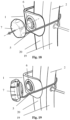
- FIG. 1 there is illustrated an apparatus 1 according to the invention for holding a wheel at a desired location.
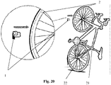
- the apparatus 1 may be employed to hold a front wheel 2 of a bicycle 21 ( Fig. 17 ).
- the apparatus 1 comprises a base part 3, a gripper part 4, an elongate flexible tether cord 5, a first coupling disc 7, and a second coupling disc 6 ( Fig. 1 ).
- the base part 3 includes a plurality of fixing openings 10 ( Fig. 1 ) to receive a plurality of corresponding fixers 18 to fix the base part 3 to a wall ( Fig. 12 ).
- the base part 3 is fixed to the wall at a suitable height to stow the bicycle 21 in a vertical configuration with the front wheel 2 held by the apparatus 1 suspended at a suitable height above the ground, and only the rear wheel 22 resting on the ground ( Fig. 17 ).
- the base part 3 includes a side opening 33 ( Fig. 1 ).
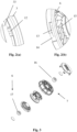
- the base part 3 also includes a protruding upstanding tooth 12 along an edge of the side opening 33 ( Fig. 2(a) ).
- the second coupling disc 6 includes an insertion opening 14 and a bayonet opening 13 along an outer edge of the second coupling disc 6 ( Fig. 2(b) ).
- the insertion opening 14 and the bayonet opening 13 correspond to the protruding upstanding tooth 12, and the insertion opening 14 and the bayonet opening 13 may receive the protruding upstanding tooth 12.
- the second coupling disc 6 may be releasably attached to a sidewall portion of the base part 3 by locating the second coupling disc 6 in the side opening 33 with the protruding upstanding tooth 12 aligned with the insertion opening 14, and then rotating the second coupling disc 6 relative to the base part 3 to move the protruding upstanding tooth 12 into the bayonet opening 13.
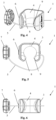
- the gripper part 4 may be releasably attached to the base part 3 by pushing the gripper part 4 into the base part 3 in a snap fit arrangement ( Figs. 1 , 4 ).
- the base part 3 is provided in the form of a generally U-shaped outer member.
- the gripper part 4 is provided in the form of a generally U-shaped inner member that nests inside the outer member and is securable thereto.
- the gripper part 4 includes a first holder element 8 to engage a first side of a tyre 20 of the front wheel 2 and a second holder element 9 to engage a second side of the tyre 20 opposite to the first side.
- the first holder element 8 is disposed in a spaced apart relationship from the second holder element 9 ( Fig. 5 ) to allow a portion of the tyre 20 to be passed therebetween ( Fig. 13 ).
- the gripper part 4 comprises a support body comprising a first sidewall portion 35, a further sidewall portion 34 disposed in a spaced apart relationship with the first sidewall portion 35 and a connector portion 11 extending between respective base regions of the first sidewall portion 35 and the further sidewall portion 34 ( Fig. 1 ).
- the first holder element 8 is provided in the form of a first gripping region of a first sidewall facing surface at a free end region of the first sidewall portion 35.
- the first gripping region 8 is convex in shape ( Fig. 5 ).
- the second holder element 9 is provided in the form of a second gripping region of a further sidewall facing surface at a free end region of the further sidewall portion 34.
- the second gripping region 9 is convex in shape ( Fig. 5 ).
- the first sidewall portion 35 and the further sidewall portion 34 are of a resilient material.
- An apex region of the first gripping region 8 and an apex region of the second gripping region 9 are disposed at a common distance from the connector portion 11 and are disposed in an opposed facing relationship ( Figs. 1 , 5 ).
- a first fixed end 31 of the tether cord 5 is securely attached to a first sidewall portion of the base part 3.
- the first fixed end 31 of the tether cord 5 is attached to the base part 3 by inserting the first end 31 through an opening 32 in the base part 3 ( Fig. 1 ), and then knotting the tether cord 5.
- the base part 3 is attached to the gripper part 4 having the first holder element 8 in the snap fit arrangement.
- a second free end 30 of the tether cord 5 is attached to the first coupling disc 7 ( Fig. 4 ).
- the tether cord 5 is extendable across a rim 19 of the front wheel 2 to secure the front wheel 2 relative to the gripper part 4 with the first holder element 8 and the second holder element 9 ( Figs. 14 , 16 ).
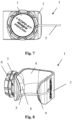
- the first coupling disc 7 includes a first magnetic part 16, and the second coupling disc 6 includes a second magnetic part 17 ( Fig. 3 ) to releasably couple the first coupling disc 7 to the second coupling disc 6 by magnetic attraction ( Figs. 4 , 8 ).
- the second coupling disc 6 is attached to the base part 3 by insertion and rotation.
- the base part 3 is attached to the gripper part 4 having the second holder element 9 in the snap fit arrangement.
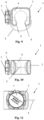
- the first coupling disc 7 is rotatable relative to the second coupling disc 6 to loop part of the tether cord 5 around the second coupling disc 6 to tension the tether cord 5 and to draw the tether cord 5 into engagement with the rim 19 of the front wheel 2 ( Figs. 15 , 16 ). In this manner the first coupling disc 7 acts as a winch to draw the tether cord 5 into place.
- the first coupling disc 7 acts as a tightening element for receiving the second free end 30 of the tether cord 5 and selectively shortening the length of the tether cord 5 between the first fixed end 31 and the first coupling disc 7 thereby tightening the tether cord 5 to a desired tension.
- the first coupling disc 7 acts as a rotatable dial that is disposed to rotate with respect to the base part 3 when the second free end 30 of the tether cord 5 is received by the first coupling disc 7. Rotation of the first coupling disc 7 then tightens the tether cord 5.
- the first coupling disc 7 includes a plurality of ratchet teeth
- the second coupling disc 6 includes a plurality of corresponding ratchet teeth 15 ( Fig. 2(b) ).
- the ratchet teeth interengage to facilitate rotation of the first coupling disc 7 relative to the second coupling disc 6 in a first direction ( Fig .16 ), and to prevent rotation of the first coupling disc 7 relative to the second coupling disc 6 in an opposite second direction.
- the second coupling disc 6 is located in the side opening 33 of the base part 3 with the protruding upstanding tooth 12 aligned with the insertion opening 14.
- the second coupling disc 6 is then rotated relative to the base part 3 to move the protruding upstanding tooth 12 into the bayonet opening 13.
- the first end 31 of the tether cord 5 is inserted through the opening 32 in the base part 3, and the tether cord 5 is knotted.
- the gripper part 4 is attached to the base part 3 by pushing the gripper part 4 into the base part 3 in the snap fit arrangement.
- the second end 30 of the tether cord 5 is attached to the first coupling disc 7.
- the base part 3 is fixed to the wall by extending the fixers 18 though the fixing openings 10 ( Fig. 12 ).
- a portion of the tyre 20 is inserted into the gripper part 4 between the first holder element 8 and the second holder element 9 ( Fig. 13 ).
- the first holder element 8 engages the first side of the tyre 20 of the front wheel 2 and the second holder element 9 engages the second side of the tyre 20.
- the tether cord 5 is extended across the rim 19 of the front wheel 2 ( Fig. 14 ).
- the first coupling disc 7 is coupled to the second coupling disc 6 by magnetic attraction between the magnetic parts 16, 17 ( Fig. 15 ).
- the first coupling disc 7 is rotated relative to the second coupling disc 6 to loop the excess part of the tether cord 5 around the second coupling disc 6 to tension the tether cord 5 and to draw the tether cord 5 into engagement with the rim 19 of the front wheel 2 ( Fig. 16 ).
- the tightened tether cord 5 secures the front wheel 2 relative to the gripper part 4.
- the ratchet teeth facilitate rotation of the first coupling disc 7 relative to the second coupling disc 6 in the first direction, and prevent rotation of the first coupling disc 7 relative to the second coupling disc 6 in the opposite second direction.
- the apparatus 1 thus holds the front wheel 2 at the desired location to stow the bicycle 21 in the vertical configuration with the front wheel 2 held by the apparatus 1 suspended at the suitable height above the ground, and the rear wheel 22 resting on the ground ( Fig. 17 ).
- the first coupling disc 7 is decoupled from the second coupling disc 6 by pulling the first coupling disc 7 away from the second coupling disc 6 ( Fig. 18 ).
- the excess part of the tether cord 5 falls loose again ( Fig. 19 ).
- the tether cord 5 is extracted from the rim 19 of the front wheel 2.
- the tyre 20 is pulled out of the gripper part 4 ( Fig. 20 ).
- the gripper part may be provided in a variety of different sizes and shapes to suit a variety of different types of wheels, for example a smaller or narrower gripper part may suit a narrower road bicycle tyre, or a wider or larger gripper part may suit a mountain bicycle tyre.
- the apparatus of the invention is also suitable for holding other types of wheels, and is not limited to holding bicycle wheels.
- apparatus of the invention may also be employed to stow a bicycle in a horizontal configuration with the front wheel and the rear wheel resting on the ground.
- the apparatus of the invention may employ any suitable means to secure the wheel relative to the first holder element and the second holder element.
- the invention is not limited to using a specific tether cord.
- the fixed end 31 of the tether cord 5 may be securely attached to the first sidewall portion 35 of the gripper part 4, rather than to the first sidewall portion of the base part 3.
- the component parts of the apparatus of the invention may be provided in any suitable shape, and the invention is not limited to the specific shapes hereinbefore described.
- the invention is not limited to a U-shaped base part, the invention is not limited to a U-shaped gripper part, the invention is not limited to a disc-shaped first coupling member, and the invention is not limited to a disc-shaped second coupling member.
Landscapes
- Engineering & Computer Science (AREA)
- Mechanical Engineering (AREA)
- Clamps And Clips (AREA)
- Handcart (AREA)
Applications Claiming Priority (1)
| Application Number | Priority Date | Filing Date | Title |
|---|---|---|---|
| GBGB2110983.0A GB202110983D0 (en) | 2021-07-30 | 2021-07-30 | Apparatus for holding a wheel member at a desired location |
Publications (3)
| Publication Number | Publication Date |
|---|---|
| EP4124548A1 true EP4124548A1 (de) | 2023-02-01 |
| EP4124548B1 EP4124548B1 (de) | 2025-07-09 |
| EP4124548C0 EP4124548C0 (de) | 2025-07-09 |
Family
ID=77651358
Family Applications (1)
| Application Number | Title | Priority Date | Filing Date |
|---|---|---|---|
| EP22187885.3A Active EP4124548B1 (de) | 2021-07-30 | 2022-07-29 | Vorrichtung zum halten eines radelements an einer gewünschten stelle |
Country Status (3)
| Country | Link |
|---|---|
| EP (1) | EP4124548B1 (de) |
| CN (1) | CN217260409U (de) |
| GB (1) | GB202110983D0 (de) |
Citations (4)
| Publication number | Priority date | Publication date | Assignee | Title |
|---|---|---|---|---|
| FR2605432A1 (fr) * | 1986-10-17 | 1988-04-22 | Arnaud Olivier | Dispositif de securite antivol a verrouillage automatique pour cycles stationnant sur la voie publique |
| US5292009A (en) * | 1992-12-24 | 1994-03-08 | Smith Terrance R | Bicycle rack |
| US20100019478A1 (en) * | 2008-07-24 | 2010-01-28 | Dufresne Jeffrey B | Stand for a motorcycle |
| US20190193621A1 (en) * | 2017-12-23 | 2019-06-27 | Maroun Youssef Ayoub | Vehicle Hauling Apparatus |
-
2021
- 2021-07-30 GB GBGB2110983.0A patent/GB202110983D0/en not_active Ceased
- 2021-11-26 CN CN202122935029.7U patent/CN217260409U/zh active Active
-
2022
- 2022-07-29 EP EP22187885.3A patent/EP4124548B1/de active Active
Patent Citations (4)
| Publication number | Priority date | Publication date | Assignee | Title |
|---|---|---|---|---|
| FR2605432A1 (fr) * | 1986-10-17 | 1988-04-22 | Arnaud Olivier | Dispositif de securite antivol a verrouillage automatique pour cycles stationnant sur la voie publique |
| US5292009A (en) * | 1992-12-24 | 1994-03-08 | Smith Terrance R | Bicycle rack |
| US20100019478A1 (en) * | 2008-07-24 | 2010-01-28 | Dufresne Jeffrey B | Stand for a motorcycle |
| US20190193621A1 (en) * | 2017-12-23 | 2019-06-27 | Maroun Youssef Ayoub | Vehicle Hauling Apparatus |
Also Published As
| Publication number | Publication date |
|---|---|
| CN217260409U (zh) | 2022-08-23 |
| GB202110983D0 (en) | 2021-09-15 |
| EP4124548B1 (de) | 2025-07-09 |
| EP4124548C0 (de) | 2025-07-09 |
Similar Documents
| Publication | Publication Date | Title |
|---|---|---|
| US5588622A (en) | Bag holder | |
| ES2383619T3 (es) | Conjunto para montaje de bolsa de filtro | |
| US20100200715A1 (en) | Quick-release adjustable mounting bracket | |
| GB2238824A (en) | Cord tie device | |
| US10104928B2 (en) | Headwear accessory mounting clip and system | |
| US20140299640A1 (en) | Magnetic bit-holder bracelet device | |
| US9476574B2 (en) | Fastening device, in particular for lighting devices | |
| CA2938278A1 (en) | Paint can holder | |
| JP2005525258A (ja) | 固定ストラップ構成体およびそのためのテンショナー | |
| US10154716B2 (en) | Camera case removable camera lens holder | |
| US6598889B1 (en) | Golf bag cart | |
| US9220662B2 (en) | Mouth-holdable bottle holder | |
| US11369184B1 (en) | Detachable paint bucket | |
| CN102821658A (zh) | 挂图装置 | |
| JP5044405B2 (ja) | 迅速連結構造物を有する自転車サドル | |
| EP1528360A1 (de) | Dreibeinstativ mit einem Laser und einem Mehrzweckgurt | |
| US8381361B2 (en) | Holding system for a line assembly | |
| EP4124548B1 (de) | Vorrichtung zum halten eines radelements an einer gewünschten stelle | |
| US20130183877A1 (en) | Friction-attached aquatic accessory | |
| US4198020A (en) | Container support | |
| ES2317593T3 (es) | Correa para la fijacion temporal de partes durante su manejo y montaje en lineas de produccion. | |
| JP2002031836A (ja) | レンズ取りつけ具 | |
| KR20060054118A (ko) | 골프 가방을 골프 카에 결합하는 방법 및 결합하는 장치 | |
| CN102273021A (zh) | 线缆组织器 | |
| ES2576840T3 (es) | Mejoras en y relativas a una plancha y procedimiento para las mismas |
Legal Events
| Date | Code | Title | Description |
|---|---|---|---|
| PUAI | Public reference made under article 153(3) epc to a published international application that has entered the european phase |
Free format text: ORIGINAL CODE: 0009012 |
|
| STAA | Information on the status of an ep patent application or granted ep patent |
Free format text: STATUS: THE APPLICATION HAS BEEN PUBLISHED |
|
| AK | Designated contracting states |
Kind code of ref document: A1 Designated state(s): AL AT BE BG CH CY CZ DE DK EE ES FI FR GB GR HR HU IE IS IT LI LT LU LV MC MK MT NL NO PL PT RO RS SE SI SK SM TR |
|
| P01 | Opt-out of the competence of the unified patent court (upc) registered |
Effective date: 20230503 |
|
| STAA | Information on the status of an ep patent application or granted ep patent |
Free format text: STATUS: REQUEST FOR EXAMINATION WAS MADE |
|
| 17P | Request for examination filed |
Effective date: 20230731 |
|
| RBV | Designated contracting states (corrected) |
Designated state(s): AL AT BE BG CH CY CZ DE DK EE ES FI FR GB GR HR HU IE IS IT LI LT LU LV MC MK MT NL NO PL PT RO RS SE SI SK SM TR |
|
| GRAP | Despatch of communication of intention to grant a patent |
Free format text: ORIGINAL CODE: EPIDOSNIGR1 |
|
| STAA | Information on the status of an ep patent application or granted ep patent |
Free format text: STATUS: GRANT OF PATENT IS INTENDED |
|
| INTG | Intention to grant announced |
Effective date: 20241115 |
|
| GRAJ | Information related to disapproval of communication of intention to grant by the applicant or resumption of examination proceedings by the epo deleted |
Free format text: ORIGINAL CODE: EPIDOSDIGR1 |
|
| STAA | Information on the status of an ep patent application or granted ep patent |
Free format text: STATUS: REQUEST FOR EXAMINATION WAS MADE |
|
| GRAP | Despatch of communication of intention to grant a patent |
Free format text: ORIGINAL CODE: EPIDOSNIGR1 |
|
| STAA | Information on the status of an ep patent application or granted ep patent |
Free format text: STATUS: GRANT OF PATENT IS INTENDED |
|
| INTC | Intention to grant announced (deleted) | ||
| INTG | Intention to grant announced |
Effective date: 20250224 |
|
| GRAS | Grant fee paid |
Free format text: ORIGINAL CODE: EPIDOSNIGR3 |
|
| GRAA | (expected) grant |
Free format text: ORIGINAL CODE: 0009210 |
|
| STAA | Information on the status of an ep patent application or granted ep patent |
Free format text: STATUS: THE PATENT HAS BEEN GRANTED |
|
| AK | Designated contracting states |
Kind code of ref document: B1 Designated state(s): AL AT BE BG CH CY CZ DE DK EE ES FI FR GB GR HR HU IE IS IT LI LT LU LV MC MK MT NL NO PL PT RO RS SE SI SK SM TR |
|
| REG | Reference to a national code |
Ref country code: GB Ref legal event code: FG4D |
|
| REG | Reference to a national code |
Ref country code: CH Ref legal event code: EP |
|
| REG | Reference to a national code |
Ref country code: IE Ref legal event code: FG4D |
|
| REG | Reference to a national code |
Ref country code: DE Ref legal event code: R096 Ref document number: 602022017212 Country of ref document: DE |
|
| U01 | Request for unitary effect filed |
Effective date: 20250808 |
|
| U07 | Unitary effect registered |
Designated state(s): AT BE BG DE DK EE FI FR IT LT LU LV MT NL PT RO SE SI Effective date: 20250821 |
|
| U20 | Renewal fee for the european patent with unitary effect paid |
Year of fee payment: 4 Effective date: 20250819 |
|
| PG25 | Lapsed in a contracting state [announced via postgrant information from national office to epo] |
Ref country code: IS Free format text: LAPSE BECAUSE OF FAILURE TO SUBMIT A TRANSLATION OF THE DESCRIPTION OR TO PAY THE FEE WITHIN THE PRESCRIBED TIME-LIMIT Effective date: 20251109 |
|
| PG25 | Lapsed in a contracting state [announced via postgrant information from national office to epo] |
Ref country code: NO Free format text: LAPSE BECAUSE OF FAILURE TO SUBMIT A TRANSLATION OF THE DESCRIPTION OR TO PAY THE FEE WITHIN THE PRESCRIBED TIME-LIMIT Effective date: 20251009 |
|
| PG25 | Lapsed in a contracting state [announced via postgrant information from national office to epo] |
Ref country code: HR Free format text: LAPSE BECAUSE OF FAILURE TO SUBMIT A TRANSLATION OF THE DESCRIPTION OR TO PAY THE FEE WITHIN THE PRESCRIBED TIME-LIMIT Effective date: 20250709 |
|
| PG25 | Lapsed in a contracting state [announced via postgrant information from national office to epo] |
Ref country code: GR Free format text: LAPSE BECAUSE OF FAILURE TO SUBMIT A TRANSLATION OF THE DESCRIPTION OR TO PAY THE FEE WITHIN THE PRESCRIBED TIME-LIMIT Effective date: 20251010 |
|
| PG25 | Lapsed in a contracting state [announced via postgrant information from national office to epo] |
Ref country code: PL Free format text: LAPSE BECAUSE OF FAILURE TO SUBMIT A TRANSLATION OF THE DESCRIPTION OR TO PAY THE FEE WITHIN THE PRESCRIBED TIME-LIMIT Effective date: 20250709 |
|
| PG25 | Lapsed in a contracting state [announced via postgrant information from national office to epo] |
Ref country code: RS Free format text: LAPSE BECAUSE OF FAILURE TO SUBMIT A TRANSLATION OF THE DESCRIPTION OR TO PAY THE FEE WITHIN THE PRESCRIBED TIME-LIMIT Effective date: 20251009 |
|
| PG25 | Lapsed in a contracting state [announced via postgrant information from national office to epo] |
Ref country code: ES Free format text: LAPSE BECAUSE OF FAILURE TO SUBMIT A TRANSLATION OF THE DESCRIPTION OR TO PAY THE FEE WITHIN THE PRESCRIBED TIME-LIMIT Effective date: 20250709 |
|
| REG | Reference to a national code |
Ref country code: CH Ref legal event code: H13 Free format text: ST27 STATUS EVENT CODE: U-0-0-H10-H13 (AS PROVIDED BY THE NATIONAL OFFICE) Effective date: 20260224 |
|
| PG25 | Lapsed in a contracting state [announced via postgrant information from national office to epo] |
Ref country code: SM Free format text: LAPSE BECAUSE OF FAILURE TO SUBMIT A TRANSLATION OF THE DESCRIPTION OR TO PAY THE FEE WITHIN THE PRESCRIBED TIME-LIMIT Effective date: 20250709 |
|
| PGFP | Annual fee paid to national office [announced via postgrant information from national office to epo] |
Ref country code: AT Payment date: 20260410 Year of fee payment: 4 |
|
| PG25 | Lapsed in a contracting state [announced via postgrant information from national office to epo] |
Ref country code: CH Free format text: LAPSE BECAUSE OF NON-PAYMENT OF DUE FEES Effective date: 20250731 Ref country code: CZ Free format text: LAPSE BECAUSE OF FAILURE TO SUBMIT A TRANSLATION OF THE DESCRIPTION OR TO PAY THE FEE WITHIN THE PRESCRIBED TIME-LIMIT Effective date: 20250709 |
|
| PG25 | Lapsed in a contracting state [announced via postgrant information from national office to epo] |
Ref country code: SK Free format text: LAPSE BECAUSE OF FAILURE TO SUBMIT A TRANSLATION OF THE DESCRIPTION OR TO PAY THE FEE WITHIN THE PRESCRIBED TIME-LIMIT Effective date: 20250709 |
|
| PLBE | No opposition filed within time limit |
Free format text: ORIGINAL CODE: 0009261 |
|
| STAA | Information on the status of an ep patent application or granted ep patent |
Free format text: STATUS: NO OPPOSITION FILED WITHIN TIME LIMIT |