EP4124305B1 - Zusammenklappbarer katheter mit superbohrung - Google Patents
Zusammenklappbarer katheter mit superbohrung Download PDFInfo
- Publication number
- EP4124305B1 EP4124305B1 EP22187383.9A EP22187383A EP4124305B1 EP 4124305 B1 EP4124305 B1 EP 4124305B1 EP 22187383 A EP22187383 A EP 22187383A EP 4124305 B1 EP4124305 B1 EP 4124305B1
- Authority
- EP
- European Patent Office
- Prior art keywords
- support frame
- catheter
- elongate body
- deployed configuration
- expanded
- Prior art date
- Legal status (The legal status is an assumption and is not a legal conclusion. Google has not performed a legal analysis and makes no representation as to the accuracy of the status listed.)
- Active
Links
Images


Classifications
-
- A—HUMAN NECESSITIES
- A61—MEDICAL OR VETERINARY SCIENCE; HYGIENE
- A61B—DIAGNOSIS; SURGERY; IDENTIFICATION
- A61B17/00—Surgical instruments, devices or methods
- A61B17/22—Implements for squeezing-off ulcers or the like on inner organs of the body; Implements for scraping-out cavities of body organs, e.g. bones; for invasive removal or destruction of calculus using mechanical vibrations; for removing obstructions in blood vessels, not otherwise provided for
- A61B17/221—Gripping devices in the form of loops or baskets for gripping calculi or similar types of obstructions
-
- A—HUMAN NECESSITIES
- A61—MEDICAL OR VETERINARY SCIENCE; HYGIENE
- A61B—DIAGNOSIS; SURGERY; IDENTIFICATION
- A61B17/00—Surgical instruments, devices or methods
- A61B17/22—Implements for squeezing-off ulcers or the like on inner organs of the body; Implements for scraping-out cavities of body organs, e.g. bones; for invasive removal or destruction of calculus using mechanical vibrations; for removing obstructions in blood vessels, not otherwise provided for
- A61B17/22031—Gripping instruments, e.g. forceps, for removing or smashing calculi
- A61B17/22032—Gripping instruments, e.g. forceps, for removing or smashing calculi having inflatable gripping elements
-
- A—HUMAN NECESSITIES
- A61—MEDICAL OR VETERINARY SCIENCE; HYGIENE
- A61M—DEVICES FOR INTRODUCING MEDIA INTO, OR ONTO, THE BODY; DEVICES FOR TRANSDUCING BODY MEDIA OR FOR TAKING MEDIA FROM THE BODY; DEVICES FOR PRODUCING OR ENDING SLEEP OR STUPOR
- A61M25/00—Catheters; Hollow probes
- A61M25/0009—Making of catheters or other medical or surgical tubes
- A61M25/001—Forming the tip of a catheter, e.g. bevelling process, join or taper
-
- A—HUMAN NECESSITIES
- A61—MEDICAL OR VETERINARY SCIENCE; HYGIENE
- A61M—DEVICES FOR INTRODUCING MEDIA INTO, OR ONTO, THE BODY; DEVICES FOR TRANSDUCING BODY MEDIA OR FOR TAKING MEDIA FROM THE BODY; DEVICES FOR PRODUCING OR ENDING SLEEP OR STUPOR
- A61M25/00—Catheters; Hollow probes
- A61M25/0067—Catheters; Hollow probes characterised by the distal end, e.g. tips
- A61M25/0074—Dynamic characteristics of the catheter tip, e.g. openable, closable, expandable or deformable
-
- A—HUMAN NECESSITIES
- A61—MEDICAL OR VETERINARY SCIENCE; HYGIENE
- A61B—DIAGNOSIS; SURGERY; IDENTIFICATION
- A61B17/00—Surgical instruments, devices or methods
- A61B2017/00526—Methods of manufacturing
-
- A—HUMAN NECESSITIES
- A61—MEDICAL OR VETERINARY SCIENCE; HYGIENE
- A61B—DIAGNOSIS; SURGERY; IDENTIFICATION
- A61B17/00—Surgical instruments, devices or methods
- A61B2017/00831—Material properties
- A61B2017/00862—Material properties elastic or resilient
-
- A—HUMAN NECESSITIES
- A61—MEDICAL OR VETERINARY SCIENCE; HYGIENE
- A61B—DIAGNOSIS; SURGERY; IDENTIFICATION
- A61B17/00—Surgical instruments, devices or methods
- A61B2017/00831—Material properties
- A61B2017/00942—Material properties hydrophilic
-
- A—HUMAN NECESSITIES
- A61—MEDICAL OR VETERINARY SCIENCE; HYGIENE
- A61B—DIAGNOSIS; SURGERY; IDENTIFICATION
- A61B17/00—Surgical instruments, devices or methods
- A61B17/22—Implements for squeezing-off ulcers or the like on inner organs of the body; Implements for scraping-out cavities of body organs, e.g. bones; for invasive removal or destruction of calculus using mechanical vibrations; for removing obstructions in blood vessels, not otherwise provided for
- A61B17/22031—Gripping instruments, e.g. forceps, for removing or smashing calculi
- A61B2017/22034—Gripping instruments, e.g. forceps, for removing or smashing calculi for gripping the obstruction or the tissue part from inside
-
- A—HUMAN NECESSITIES
- A61—MEDICAL OR VETERINARY SCIENCE; HYGIENE
- A61B—DIAGNOSIS; SURGERY; IDENTIFICATION
- A61B17/00—Surgical instruments, devices or methods
- A61B17/22—Implements for squeezing-off ulcers or the like on inner organs of the body; Implements for scraping-out cavities of body organs, e.g. bones; for invasive removal or destruction of calculus using mechanical vibrations; for removing obstructions in blood vessels, not otherwise provided for
- A61B2017/22051—Implements for squeezing-off ulcers or the like on inner organs of the body; Implements for scraping-out cavities of body organs, e.g. bones; for invasive removal or destruction of calculus using mechanical vibrations; for removing obstructions in blood vessels, not otherwise provided for with an inflatable part, e.g. balloon, for positioning, blocking, or immobilisation
-
- A—HUMAN NECESSITIES
- A61—MEDICAL OR VETERINARY SCIENCE; HYGIENE
- A61B—DIAGNOSIS; SURGERY; IDENTIFICATION
- A61B17/00—Surgical instruments, devices or methods
- A61B17/22—Implements for squeezing-off ulcers or the like on inner organs of the body; Implements for scraping-out cavities of body organs, e.g. bones; for invasive removal or destruction of calculus using mechanical vibrations; for removing obstructions in blood vessels, not otherwise provided for
- A61B2017/22079—Implements for squeezing-off ulcers or the like on inner organs of the body; Implements for scraping-out cavities of body organs, e.g. bones; for invasive removal or destruction of calculus using mechanical vibrations; for removing obstructions in blood vessels, not otherwise provided for with suction of debris
-
- A—HUMAN NECESSITIES
- A61—MEDICAL OR VETERINARY SCIENCE; HYGIENE
- A61B—DIAGNOSIS; SURGERY; IDENTIFICATION
- A61B17/00—Surgical instruments, devices or methods
- A61B17/22—Implements for squeezing-off ulcers or the like on inner organs of the body; Implements for scraping-out cavities of body organs, e.g. bones; for invasive removal or destruction of calculus using mechanical vibrations; for removing obstructions in blood vessels, not otherwise provided for
- A61B2017/22094—Implements for squeezing-off ulcers or the like on inner organs of the body; Implements for scraping-out cavities of body organs, e.g. bones; for invasive removal or destruction of calculus using mechanical vibrations; for removing obstructions in blood vessels, not otherwise provided for for crossing total occlusions, i.e. piercing
-
- A—HUMAN NECESSITIES
- A61—MEDICAL OR VETERINARY SCIENCE; HYGIENE
- A61B—DIAGNOSIS; SURGERY; IDENTIFICATION
- A61B17/00—Surgical instruments, devices or methods
- A61B17/22—Implements for squeezing-off ulcers or the like on inner organs of the body; Implements for scraping-out cavities of body organs, e.g. bones; for invasive removal or destruction of calculus using mechanical vibrations; for removing obstructions in blood vessels, not otherwise provided for
- A61B17/221—Gripping devices in the form of loops or baskets for gripping calculi or similar types of obstructions
- A61B2017/2215—Gripping devices in the form of loops or baskets for gripping calculi or similar types of obstructions having an open distal end
-
- A—HUMAN NECESSITIES
- A61—MEDICAL OR VETERINARY SCIENCE; HYGIENE
- A61M—DEVICES FOR INTRODUCING MEDIA INTO, OR ONTO, THE BODY; DEVICES FOR TRANSDUCING BODY MEDIA OR FOR TAKING MEDIA FROM THE BODY; DEVICES FOR PRODUCING OR ENDING SLEEP OR STUPOR
- A61M25/00—Catheters; Hollow probes
- A61M25/0021—Catheters; Hollow probes characterised by the form of the tubing
- A61M25/0023—Catheters; Hollow probes characterised by the form of the tubing by the form of the lumen, e.g. cross-section, variable diameter
- A61M2025/0024—Expandable catheters or sheaths
-
- A—HUMAN NECESSITIES
- A61—MEDICAL OR VETERINARY SCIENCE; HYGIENE
- A61M—DEVICES FOR INTRODUCING MEDIA INTO, OR ONTO, THE BODY; DEVICES FOR TRANSDUCING BODY MEDIA OR FOR TAKING MEDIA FROM THE BODY; DEVICES FOR PRODUCING OR ENDING SLEEP OR STUPOR
- A61M25/00—Catheters; Hollow probes
- A61M25/0021—Catheters; Hollow probes characterised by the form of the tubing
- A61M25/0023—Catheters; Hollow probes characterised by the form of the tubing by the form of the lumen, e.g. cross-section, variable diameter
- A61M2025/0025—Catheters; Hollow probes characterised by the form of the tubing by the form of the lumen, e.g. cross-section, variable diameter having a collapsible lumen
-
- A—HUMAN NECESSITIES
- A61—MEDICAL OR VETERINARY SCIENCE; HYGIENE
- A61M—DEVICES FOR INTRODUCING MEDIA INTO, OR ONTO, THE BODY; DEVICES FOR TRANSDUCING BODY MEDIA OR FOR TAKING MEDIA FROM THE BODY; DEVICES FOR PRODUCING OR ENDING SLEEP OR STUPOR
- A61M25/00—Catheters; Hollow probes
- A61M25/01—Introducing, guiding, advancing, emplacing or holding catheters
- A61M25/06—Body-piercing guide needles or the like
- A61M25/0662—Guide tubes
- A61M2025/0681—Systems with catheter and outer tubing, e.g. sheath, sleeve or guide tube
-
- A—HUMAN NECESSITIES
- A61—MEDICAL OR VETERINARY SCIENCE; HYGIENE
- A61M—DEVICES FOR INTRODUCING MEDIA INTO, OR ONTO, THE BODY; DEVICES FOR TRANSDUCING BODY MEDIA OR FOR TAKING MEDIA FROM THE BODY; DEVICES FOR PRODUCING OR ENDING SLEEP OR STUPOR
- A61M2205/00—General characteristics of the apparatus
- A61M2205/02—General characteristics of the apparatus characterised by a particular materials
- A61M2205/0216—Materials providing elastic properties, e.g. for facilitating deformation and avoid breaking
-
- A—HUMAN NECESSITIES
- A61—MEDICAL OR VETERINARY SCIENCE; HYGIENE
- A61M—DEVICES FOR INTRODUCING MEDIA INTO, OR ONTO, THE BODY; DEVICES FOR TRANSDUCING BODY MEDIA OR FOR TAKING MEDIA FROM THE BODY; DEVICES FOR PRODUCING OR ENDING SLEEP OR STUPOR
- A61M2205/00—General characteristics of the apparatus
- A61M2205/02—General characteristics of the apparatus characterised by a particular materials
- A61M2205/0238—General characteristics of the apparatus characterised by a particular materials the material being a coating or protective layer
-
- A—HUMAN NECESSITIES
- A61—MEDICAL OR VETERINARY SCIENCE; HYGIENE
- A61M—DEVICES FOR INTRODUCING MEDIA INTO, OR ONTO, THE BODY; DEVICES FOR TRANSDUCING BODY MEDIA OR FOR TAKING MEDIA FROM THE BODY; DEVICES FOR PRODUCING OR ENDING SLEEP OR STUPOR
- A61M25/00—Catheters; Hollow probes
- A61M25/01—Introducing, guiding, advancing, emplacing or holding catheters
- A61M25/06—Body-piercing guide needles or the like
- A61M25/0662—Guide tubes
Definitions
- the present invention generally relates devices for removing acute blockages from blood vessels during intravascular medical treatments. More specifically, the present invention relates to retrieval catheters with expandable tips into which an object or objects can be retrieved.
- Clot retrieval aspiration catheters and devices are used in mechanical thrombectomy for endovascular intervention, often in cases where patients are suffering from conditions such as acute ischemic stroke (AIS), myocardial infarction (MI), and pulmonary embolism (PE).
- AIS acute ischemic stroke
- MI myocardial infarction
- PE pulmonary embolism
- Accessing the neurovascular bed in particular is challenging with conventional technology, as the target vessels are small in diameter, remote relative to the site of insertion, and highly tortuous.
- Traditional devices are often either too large in profile, lack the deliverability and flexibility needed to navigate particularly tortuous vessels, or are not effective at removing a clot when delivered to the target site.
- the bore lumen of these catheters can be nearly as large as the guide and/or sheath through which they are delivered, and the expandable tip can expand to be larger still.
- the expandable tips can be, for example, an underlying metallic support frame made from a suitably elastic material so that it can expand when deployed from the guide and/or sheath.
- the frame can be shaped to provide a clinically atraumatic vessel crossing profile with the ability to maintain an inner diameter and recover its shape when displaced laterally.
- a polymeric jacket can cover the frame to provide a soft outer layer for catheter advancement.
- the expandable tip can be of fully polymeric construction of one or multiple materials. However, designs with fixed braids, frames, or expanded sizes do not allow for any additional expansion of the tip which can complicate the interaction with and reception of a clot during ingestion.
- Catheter designs attempting to overcome the above-mentioned design challenges would need to have a large bore and an expandable tip with sufficient hoop strength in the expanded state to resist aspiration forces without collapse while having a structure capable of folding down consistently and repeatably when retrieved into an outer guide and/or sheath.
- the tip structure needs to have the flexibility and elasticity to survive the severe mechanical strains imparted when navigating the tortuous vasculature, while also being capable of expanding elastically as a clot is ingested for better interaction with and retention of the clot.
- Tip designs disclosed herein can maintain good pushability but are also sized to be advanced within an outer sheath, and then in the expanded state in a vessel with minimal tendency to further over-expand outward when placed in compression. Such over-expansion can increase the delivery forces for the catheter and can also result in the aspiration catheter binding within the outer guide or sheath through which it is delivered. Further expansion in a vessel can damage vessel walls or snag when advanced.
- WO2021/016213A1 describes devices and methods for aspiration of thrombus.
- EP3705066A1 describes an actuated clot retrieval catheter.
- US2021/154433A1 describes an clot retrieval device with outer sheath and inner catheter.
- US2020/205845A1 describes devices and methods for removing obstructive material from an intravascular site.
- US2021/153884A1 describes an actuated expandable mouth thrombectomy catheter.
- the invention is defined by claim 1. Embodiments of the invention are defined by the dependent claims. It is an object of the present designs to provide devices and methods to meet the above-stated needs.
- the designs can be for a clot retrieval catheter capable of remove a clot from cerebral arteries in patients suffering AIS, from coronary native or graft vessels in patients suffering from MI, and from pulmonary arteries in patients suffering from PE and from other peripheral arterial and venous vessels in which a clot is causing an occlusion.
- a device can be a large bore catheter having a proximal elongate body with a proximal end, a distal end, an internal lumen, and a longitudinal axis extending therethrough.
- the elongate body can terminate at a distal expansile tip, which can be integrally-formed or fixedly connected.
- the tip can have a support frame with a framework of struts configured to be expanded and collapsed between a collapsed delivery configuration and an expanded deployed configuration when the catheter is advanced and retracted from an outer guide and/or sheath at the site of an occlusive thrombus.
- the support frame can have a longitudinal length sized to be less than twice the inner diameter of the elongate body in the expanded deployed configuration. In other examples, the longitudinal length can be less than three times the inner diameter of the elongate body in the expanded deployed configuration.
- the support frame can also have a range of inner and outer diameters.
- the support frame can have a maximum inner diameter (or maximum outer diameter) in the expanded state equal to or less than the diameter of a target vessel just proximal of a target clot.
- the expanded support frame can be sized to have a larger inner diameter than the inner diameter of an outer sheath through which it is delivered.
- the support frame can have an inner diameter of approximately 1.78mm (0.070”) in the collapsed delivery configuration and a maximum inner diameter in a range of approximately 2.03 - 3.05mm (0.080 - 0.120 inches) in the expanded deployed configuration.
- the difference between the inner diameters of the support frame in the expanded deployed configuration and the collapsed delivery configuration can be more than 10% of the inner diameter in the collapsed delivery configuration. In similar designs, the difference between the inner diameters of the support frame in the expanded deployed configuration and the collapsed delivery configuration can be more than 20% of the inner diameter in the collapsed delivery configuration.
- the framework of struts has one or more hoop segments and a plurality of deformable cells.
- the hoop segments and cells can be configured in such a way to balance the overall flexibility and radial force the frame is capable of.
- the hoop segments and cells can be joined directly or connected through one or more axial spines which can linking the support frame with the elongate body.
- the cells can be arranged in a variety of ways within the support frame. In one example, there can be a single axial row of cells on one side of the frame, the remainder of the frame circumference made up of the hoop segments. In other example there can be two rows of axial cells configured 180 degrees apart, or at some other orientation, with hoop segments linking the rows.
- the cells are configured to assume an axially extended profile elongated parallel to the longitudinal axis when the support frame is in the collapsed delivery configuration; and expand to a radially extended profile elongated normal to the longitudinal axis when the support frame is in the expanded deployed configuration. In this way, the cells take up a very small percentage of the circumference of the support frame when collapsed, and a substantially larger percentage when expanded. This means that the one or more hoop segments account for a greater percentage of the inner diameter when the support frame is collapsed than when it is expanded. In some instances, the cells can make up less than 30% of the circumference of the support frame when the frame is in the collapsed delivery configuration. More preferably, the cells would constitute less than 20% of the circumference in the collapsed configuration.
- the orientation of the struts of the deformable cells can be used to express the degree to which they are collapsed or expanded.
- the struts of the deformable cells can form an angle with the longitudinal axis that is less than 30 degrees in the collapsed delivery configuration.
- the struts of the deformable cells can form an angle with the longitudinal axis that is greater than 45 degrees.
- the cells can also have an arc length forming a proportion of the circumference which is significantly smaller when the cells and tip are in the collapsed state than when in the deployed expanded state.
- the struts of the deformable cells can have a first arc length in the collapsed delivery configuration less than a second arc length in the expanded deployed configuration.
- the cells of the support frame occupy a small percentage of the support frame circumference when in the collapsed delivery configuration, this can mean that the one or more hoop segments account for a greater percentage of the inner diameter when the support frame is collapsed than when it is expanded.
- the designs herein can be for a clot retrieval catheter with a large bore lumen and a distal tip that can expand to a diameter larger than that of the guide or sheath through which it is delivered when advanced beyond the distal end.
- the designs can have a proximal elongate body for the shaft of the catheter, and a distal tip with an expanding metallic support frame and outer polymeric jacket to give the tip atraumatic properties and the ability to flexibly expand further in the expanded deployed configuration when ingesting a clot.
- the support frame can be designed so that the expanding/collapsing movement is focused a small portion of the circumference though a plurality of deformable cells that can collapse to be almost flat and parallel to the longitudinal axis for ease of deliverability, but expand with a very steep, nearly vertical angle for good resistance to collapse under aspiration.
- the catheter frame and tip can be sufficiently flexible to navigate highly tortuous areas of the anatomy and be able to recover and maintain the inner diameter of the lumen when displaced in a vessel.
- These products such as angiographic materials, mechanical thrombectomy devices, microcatheters, and guidewires are widely used in laboratory and medical procedures.
- these products are employed in conjunction with the devices and methods (not claimed) of this invention in the description below, their function and exact constitution are not described in detail. While the description is in many cases in the context of thrombectomy treatments in intercranial arteries, the disclosure may be adapted for other procedures and in other body passageways as well.
- the clot retrieval catheter 100 can have a flexible elongate body 110 serving as a shaft with a large internal bore (which in some cases can be 2.29mm (0.080 inches) or larger) and a distal tip section having a collapsible support frame 210.
- the large bore helps the catheter to be delivered to a target site by a variety of methods. These can include over a guidewire, over a microcatheter, with a dilator/access tool, or by itself.
- the design of the tip can be configured so that the entire catheter 100 can be delivered through (and retrieved back through) common standard 6F sheaths/8F guides, which typically have inner lumens of less than 2.29mm (0.090 inches).
- the tip can self-expand once advanced to an unconstrained position distal to the distal end 32 of the guide sheath 30.
- the support frame 210 of the tip is designed to be able to resist collapse from the forces of aspiration, have excellent lateral flexibility in both the expanded and collapsed states, and an atraumatic profile to prevent snagging on bifurcations in vessels.
- FIG. 2A and FIG. 2B show a closer view of the distal region of the catheter 100 of FIG. 1 confined within, and then delivered beyond, the guide sheath 30.
- the catheter 100 can have a tubular elongate body 110 configured around a longitudinal axis 111.
- the structure for the elongate body 110 can define the catheter lumen, which can be used for the delivery of auxiliary devices, contrast injection, and direct distal aspiration to a clot face.
- the underlying structure of the elongate body 110 can be, for example, a frame cut from a hypotube of a superelastic material with shape memory properties, such as Nitinol with an internal low friction liner and outer polymer jacket or jackets 180 that can be reflowed into the structure during manufacturing. Alternately, a more traditional polymer and/or metal braid or coil support structure can be used, or some combination of these.
- the elongate body can be sized to be compatible with relatively low-profile access sheaths and catheters, so that a puncture wound in the patient's groin (in the case of femoral access) can be easily and reliably closed.
- the clot retrieval catheter 100 can be required to pass through the lumen 33 of a sheath or guide 30 with an inner diameter 31 of less than 2.80 mm (0.110 inches), preferably 2.29mm (0.090 inches), in some cases less than 2.21mm (0.087 inches), and most preferably less than 2.16mm (0.085 inches).
- the inner diameter can be less than 2.03mm (0.080 inches) and can be as small as 1.78mm (0.070 inches).
- the catheter shaft can have an overall delivery profile with an inner diameter 115 of approximately 1.70 - 1.88mm (0.067 - 0.074 inches) (0.084 inch or 2 mm outer diameter), and yet be able to expand its distal tip and mouth to a size just smaller than the diameter of the vessel approximate where the clot is located, which could be as large as 5 mm. It can be appreciated that larger or smaller catheter shafts can be used if paired with a larger or smaller guide/sheath.
- the support frame 210 can similarly be sized for compatibility.
- the support frame 210 can have an inner diameter 222 in the collapsed delivery configuration sized so that radial forces are not excessively high for delivery through the selected guide sheath 30, which can for example have an inner diameter of 2.16mm (0.085 inches).
- the support frame 210 can grow radially such that the tip is just smaller in diameter than the target vessel. For example, a large size of approximately 3-5 mm for clots in the ICA, an intermediate size for proximal / large M!
- the tip can have a maximum inner diameter 224 within a range of approximately 2.03 - 3.05mm (0.080 - 0.120 inches) in the expanded deployed configuration.
- a relative measure of how steeply the funnel profiled portion of the support frame 210 of the expandable tip grows can be taken from an angle corresponding to the increase in size relative to increasing distal distance along the longitudinal axis 111.
- This flare angle can be separated into a collapsed angle 215 and an expanded angle 216 as seen in FIG. 2A and FIG. 2B , respectively.
- the collapsed flare angle 215 would ideally be as close to 0 degrees as possible for deliverability and column strength.
- the expanded flare angle 216 would ideally be as close to 90 degrees (or vertical with respect to the axis 111) as possible for good radial force capacity.
- the overall length of the frame 210 can also be kept as short as practical. In some examples, this longitudinal length 211 can be less than twice, or preferably less than three times, the inner diameter 115 of the elongate body.
- a short frame 210 can maintain good hoop stiffness while maintaining excellent flexibility through having a short lever distance to hinge off the elongate body 110.
- a short frame can also be tailored to minimize stretch and deformation in the outer polymer jackets.
- specifications for the frame 210 can include that the expanded tip has a "crush" strength (utilizing a flat plate squash test) of greater than a specified value (or within a range of values) in the expanded configuration.
- the design can be specified to have a radial force of less than a specified value (or within a range of values) in the collapsed/delivery configuration.
- FIG. 3A A developed view of an example laser cut pattern for an example support frame 210, post-expansion, for the large bore catheter is depicted in FIG. 3A .
- the more proximal portion of the support frame 210 can be cut to the diameter of the elongate body 110 (or cut integrally from the same hypotube), while the more distal portion can be expanded to a circumference dimension 225 at the distal end 214 which would yield the desired expanded inner diameter of the support frame.
- the frame 210 can be a laser cut Nitinol or steel network of interconnected struts.
- the network of struts can be relatively dense to provide good scaffolding for the outer jackets, especially in regions where a particularly soft and highly flexible polymer or blend is chosen.
- the network of struts making up the support frame 210 has two axial series of deformable cells 220 connected by hoop segments 213.
- the deformable cells 220 are capable of elongating circumferentially with respect to the axis 111 when the frame is in radially expanded to the deployed configuration, and elongating axially (flattening) with respect to the longitudinal axis when the support frame is reduced to the collapsed delivery configuration for advancement (or when the frame is withdrawn back into an outer sheath).
- the cells 220 can be substantially diamond shape to allow the vertices to facilitate more uniform deformation/expansion as shown or take some other profile such as a rounded or ovular shape.
- the cell struts assume a steep, more vertical orientation with respect to the longitudinal axis 111. This gives the frame better compressive hoop strength in an expanded state to resist collapse of the tip under aspiration. Additionally, steeper cell angles can reduce the tendency of the support frame to further expand radially or over-expand when the catheter 100 is in compression being advanced through a vessel independently (after deployment from the guide sheath) with the frame in the expanded state. This can help the expanded tip to avoid snagging in vessels, particularly in tight bends and when being pushed through vessels of progressively smaller diameters.
- FIG. 3B shows an inset view of a sample configuration for the deformable cells 220 when the support frame 210 is in the collapsed delivery configuration.
- the struts of the cells 220 can assume a shallow, almost horizontal angle to give the support frame 210 more column stiffness and pushability. Further, shallow angles can resist the tendency of the frame to expand when the catheter is advanced through the guide and/or sheath in the collapsed state. This resistance can help to prevent binding and high delivery forces during advancement.
- the hoop segments 213 are of fixed size and do not expand, the change in tip circumference (and thus diameter) due to the expansion of the support frame 210 is due in its entirety to the elongation of the deformable cells 220. As a result, it is desirable for the cells to fold as flat as possible (and account for as little of the total circumference of the frame) in the collapsed delivery configuration for peak performance. Similarly, it is preferred that the cells come together to be near vertical members when in the expanded deployed configuration. Therefore, since the hoop segments 213 are of fixed size, the percentage of the inner diameter 222 of the support frame 210 accounted for by the segments in the collapsed delivery configuration is greater than the percentage of the expanded inner diameter 224 accounted for by the hoop segments in the deployed configuration.
- the axial series of deformable cells 220 as shown in FIG. 3A and FIG. 3B are arranged in a parallel rows with respect to the longitudinal axis 111, but it can be appreciated that they can be offset circumferentially from one another, even by 90 degrees or more within a lattice.
- a single circumferential strut could be used to connect the cells 220, and the hoop segments 213 could be axially offset into the interstitial spaces between these struts.
- the pattern of the cells 220 and hoop segments 213 can be symmetric about the axis 111 so that expansion and collapse/wrap down of the support frame 210 can be consistent and repeatable.
- the struts of the cells 220 can form an arc length 219 that is a smaller overall component of the tip circumference.
- FIG. 4 The funnel shape of an expanded support frame 210 similar to that of FIG. 3A is illustrated in FIG. 4 .
- This profile can have a gradual taper as shown so that a captured clot is progressively compressed proximally until there is little to no resistance to clot entry into the elongate body 110.
- the assembled support frame 210 can have a smooth, low friction inner surface without any sagging of the outer jacket (not shown) or other structural protrusions into the interior during aspiration.
- the elongate body 110 can have a number of forms and, as mentioned, can be formed integrally with the support frame 210 by laser cutting the same hypotube.
- One or more connecting spines 218 can be used to link the body and the tip.
- the spine or spines 218 can add stiffness and define planes or axis about which the support frame can bend relative to the expansile body.
- Spines can have a fixed, rigid connections as shown or can be of a form which allows more flexing such as a waveform shape or threaded eyelet.
- the shape of the deformable cells 220 can also vary, so long as apices, creases, or other biasing features exist for reliable expansion and folding.
- the cells can have an arc length 219, 229 forming a proportion of the circumference in the collapsed and deployed states.
- the struts of the cells can form a smaller first arc length 219 in the collapsed delivery configuration and a larger second arc length 229 when the tip is expanded.
- the cell arc length can expand by at least 50%, but preferably up to 100% or more between the collapsed and expanded configurations. In some examples, the arc length can increase by as much as 200% or more between the collapsed and expanded states.
- the struts of the cells 220 can form different angles with the longitudinal axis 111 in the collapsed delivery configuration and the expanded deployed configuration. As the cells are the primary deforming members between the states of the frame 210, the angle achieved in one configuration (either collapsed or expanded) influences what can be achieved in the other, so a design balance for performance must be struck.
- the cell angle 223 when the support frame 210 is in the expanded deployed configuration as seen in FIG. 4 would preferably be as close to 90 degrees as possible with the axis 111 to maximize the radial force capabilities of the frame.
- a steep angle can allow for some additional frame expansion without overexpansion when being advanced through a vessel.
- the expanded cell angle 223 can be greater than 45 degrees, but ideally greater than 60 degrees and most preferably greater than 70 degrees. Expansion and folding of the frame can function at lower angles, but increasingly steep angles can give the frame greater hoop strength.
- a laser cut elongate body support tube 110 with a distal radially expandable support frame 210 is formed in FIG. 7B .
- the elongate body can have a plurality of ribs 118 extending along a longitudinal axis 111 between a proximal end 112 and a distal end 114.
- the elongate body 110 and tip support frame 210 can be cut from a hypotube of NiTi or another shape memory superelastic alloy so that the solid state phase transformations can be designed to dictate the constrained and unconstrained diameters of the frame.
Landscapes
- Health & Medical Sciences (AREA)
- Life Sciences & Earth Sciences (AREA)
- Surgery (AREA)
- General Health & Medical Sciences (AREA)
- Engineering & Computer Science (AREA)
- Veterinary Medicine (AREA)
- Biomedical Technology (AREA)
- Heart & Thoracic Surgery (AREA)
- Public Health (AREA)
- Animal Behavior & Ethology (AREA)
- Nuclear Medicine, Radiotherapy & Molecular Imaging (AREA)
- Orthopedic Medicine & Surgery (AREA)
- Vascular Medicine (AREA)
- Medical Informatics (AREA)
- Molecular Biology (AREA)
- Hematology (AREA)
- Anesthesiology (AREA)
- Pulmonology (AREA)
- Biophysics (AREA)
- Media Introduction/Drainage Providing Device (AREA)
- Surgical Instruments (AREA)
Claims (14)
- Katheter (100) mit großer Bohrung, umfassend:eine Längsachse;einen länglichen Körper (110), umfassend ein Lumen, ein proximales Ende und ein distales Ende;einen Stützrahmen (210) an dem distalen Ende des länglichen Körpers, der eine zusammengeklappte Zuführkonfiguration und eine expandierte entfaltete Konfiguration aufweist, der Stützrahmen (210) umfassend ein Strebengerüst, umfassend ein oder mehrere Reifensegmente (213) und eine Vielzahl von verformbaren Zellen (220), wobei die verformbaren Zellen (220) Spitzen, Falten oder andere Vorspannmerkmale derart aufweisen, dass die verformbaren Zellen (220) konfiguriert sind, um ein axial ausgedehntes Profil anzunehmen, wenn sich der Stützrahmen (210) in der zusammengeklappten Zuführkonfiguration befindet, und sich zu einem radial ausgedehnten Profil zu expandieren, wenn sich der Stützrahmen (210) in der expandierten entfalteten Konfiguration befindet;wobei die expandierte entfaltete Konfiguration des Stützrahmens (210) dimensioniert ist, um einen größeren Innendurchmesser als der Innendurchmesser einer Außenhülle aufzuweisen,dadurch gekennzeichnet, dass das eine oder die mehreren Reifensegmente (213) und die Vielzahl von verformbaren Zellen (220) einen Prozentsatz des Umfangs des Stützrahmens (210) ausmachen, und wobei das eine oder die mehreren Reifensegmente (213) von fester Dimension derart sind, dass der Prozentsatz, den das eine oder die mehreren Reifensegmente (213) ausmachen, in der zusammengeklappten Zuführkonfiguration höher als der Prozentsatz in der expandierten entfalteten Konfiguration ist, wobei die verformbaren Zellen (220) in der expandierten entfalteten Konfiguration einen Prozentsatz einnehmen, der größer als in der zusammengeklappten Zuführkonfiguration ist.
- Katheter nach Anspruch 1, die Streben der verformbaren Zellen (220) umfassend einen Winkel mit der Längsachse von i) kleiner als 30 Grad in der zusammengeklappten Zuführkonfiguration oder ii) höher als 45 Grad in der expandierten entfalteten Konfiguration.
- Katheter nach Anspruch 1 oder 2, der Stützrahmen (210) ferner umfassend i) eine axiale Reihe von verformbaren Zellen (220) oder ii) zwei axiale Reihen von verformbaren Zellen (220).
- Katheter nach einem der vorstehenden Ansprüche, die verformbaren Zellen (220) umfassend weniger als 30 % des Umfangs des Stützrahmens (210), wenn sich der Rahmen in der zusammengeklappten Zuführkonfiguration befindet.
- Katheter nach einem der vorstehenden Ansprüche, der Stützrahmen (210) ferner umfassend eine Längslänge, die dimensioniert ist, um kleiner als ein Dreifaches eines Innendurchmessers des länglichen Körpers zu sein.
- Katheter nach einem der vorstehenden Ansprüche, der Stützrahmen (210) ferner umfassend einen Innendurchmesser von etwa 1,78 mm (0,070 Zoll) in der zusammengeklappten Zuführkonfiguration und einen maximalen Innendurchmesser in einem Bereich von etwa 2,03-3,05 mm (0,080 -0,120 Zoll) in der expandierten entfalteten Konfiguration.
- Katheter nach einem der vorstehenden Ansprüche, wobei der Unterschied zwischen dem Innendurchmesser des Stützrahmens (210) in der expandierten entfalteten Konfiguration und dem Innendurchmesser des Stützrahmens (210) in der zusammengeklappten Zuführkonfiguration mehr als 10 % des Innendurchmessers in der zusammengeklappten Zuführkonfiguration beträgt.
- Katheter nach einem der vorstehenden Ansprüche, die Streben der verformbaren Zellen (220) umfassend eine erste Bogenlänge in der zusammengeklappten Zuführkonfiguration, die kleiner als eine zweite Bogenlänge in der expandierten entfalteten Konfiguration ist.
- Katheter nach einem der vorstehenden Ansprüche, der Stützrahmen (210) ferner umfassend einen oder mehrere Verbindungsrücken (218), die die Reifensegmente (213) des Stützrahmens (210) mit dem länglichen Körper (110) verbinden.
- Katheter nach einem der vorstehenden Ansprüche, der Stützrahmen (210) umfassend einen maximalen Außendurchmesser in der expandierten entfalteten Konfiguration, der kleiner als ein Innendurchmesser eines Zielgefäßes an einer Behandlungsstelle ist.
- Katheter nach einem der vorstehenden Ansprüche, wobei die Streben der verformbaren Zellen (220) einen Zellwinkel mit der Längsachse von höher als 70 Grad in der expandierten entfalteten Konfiguration formen.
- Katheter nach einem der vorstehenden Ansprüche, wobei die Streben von mindestens einem Abschnitt des Stützrahmens (210) einen Aufweitungswinkel mit der Längsachse formen, wobei der Aufweitungswinkel konfiguriert ist, um etwa null Grad in der zusammengeklappten Zuführkonfiguration und etwa 90 Grad in der expandierten entfalteten Konfiguration zu betragen.
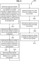
- Verfahren zum Herstellen eines Katheters nach einem der vorstehenden Ansprüche, das Verfahren umfassend die Schritte:Anordnen einer Innenauskleidung (160) um einen ersten Applikationsdorn (510) herum;Formen eines länglichen Körpers (110), der um eine Längsachse herum eingerichtet ist, und eines Stützrahmens (210), der mit dem distalen Ende des länglichen Körpers (110) verbunden ist, der Stützrahmen (210)umfassend ein Strebengerüst, umfassend ein oder mehrere Reifensegmente (213) und eine Vielzahl von verformbaren Zellen (220), die konfiguriert sind, um ein axial ausgedehntes Profil anzunehmen, das einen spitzen Zellwinkel mit der Längsachse formt, wenn sich der Stützrahmen (210) in der zusammengeklappten Zuführkonfiguration befindet, und sich zu einem radial ausgedehnten Profil expandiert, wenn sich der Stützrahmen (210) in der expandierten entfalteten Konfiguration befindet;wobei die expandierte entfaltete Konfiguration des Stützrahmens (210) dimensioniert ist, um einen größeren Innendurchmesser als der Innendurchmesser einer Außenhülle aufzuweisen, wobei das eine oder die mehreren Reifensegmente (213) einen Prozentsatz des Umfangs des Stützrahmens (210) ausmachen und wobei das eine oder die mehreren Reifensegmente (213) von fester Dimension derart sind, dass der Prozentsatz in der zusammengeklappten Zuführkonfiguration höher als der Prozentsatz in der expandierten entfalteten Konfiguration ist;Positionieren des länglichen Körpers (110) und eines Stützkörpers (210) an einem im Wesentlichen röhrenförmigen zweiten überdimensionierten Dorn (520), der zweite überdimensionierte Dorn (520) umfassend einen Außendurchmesser, der höher als der Außendurchmesser der Innenauskleidung an dem ersten Applikationsdorn (510) ist;Abkühlen des länglichen Körpers (110) und des Stützrahmens (210) auf eine Temperatur unterhalb der Austenitendtemperatur;Entfernen des zweiten überdimensionierten Dorns (520) aus dem länglichen Körper (110);Positionieren des länglichen Körpers (110) um die Innenauskleidung (160) und den ersten Applikationsdorn (510) herum;Aufschmelzen oder Laminieren eines oder mehrerer proximaler Außenpolymermäntel auf den länglichen Körper (110);Entfernen des ersten Applikationsdorns (510) und Einführen eines dritten aufgeweiteten Dorns (530) in den expandierten Rahmen des Stützkörpers (210);Platzieren eines distalen weichen elastischen Mantels über dem Rahmen des Stützkörpers (210) und Laminieren des Mantels auf den länglichen Körper (110) und den Stützkörper (210); undEntfernen des dritten aufgeweiteten Dorns (530).
- Verfahren nach Anspruch 13, ferner umfassend den Schritt eines Applizierens einer hydrophilen Innenbeschichtung auf das Innere und Äußere des Stützkörpers (210), optional ferner umfassend den Schritt eines Verschmelzens des weichen elastischen Mantels des Stützkörpers (210) mit dem einen oder den mehreren proximalen Außenpolymermänteln des länglichen Körpers (110).
Priority Applications (1)
| Application Number | Priority Date | Filing Date | Title |
|---|---|---|---|
| EP24213864.2A EP4537773A3 (de) | 2021-07-29 | 2022-07-28 | Zusammenklappbarer superbohrungskatheter |
Applications Claiming Priority (1)
| Application Number | Priority Date | Filing Date | Title |
|---|---|---|---|
| US202163203714P | 2021-07-29 | 2021-07-29 |
Related Child Applications (1)
| Application Number | Title | Priority Date | Filing Date |
|---|---|---|---|
| EP24213864.2A Division EP4537773A3 (de) | 2021-07-29 | 2022-07-28 | Zusammenklappbarer superbohrungskatheter |
Publications (4)
| Publication Number | Publication Date |
|---|---|
| EP4124305A2 EP4124305A2 (de) | 2023-02-01 |
| EP4124305A3 EP4124305A3 (de) | 2023-03-22 |
| EP4124305C0 EP4124305C0 (de) | 2024-11-20 |
| EP4124305B1 true EP4124305B1 (de) | 2024-11-20 |
Family
ID=82781288
Family Applications (2)
| Application Number | Title | Priority Date | Filing Date |
|---|---|---|---|
| EP24213864.2A Pending EP4537773A3 (de) | 2021-07-29 | 2022-07-28 | Zusammenklappbarer superbohrungskatheter |
| EP22187383.9A Active EP4124305B1 (de) | 2021-07-29 | 2022-07-28 | Zusammenklappbarer katheter mit superbohrung |
Family Applications Before (1)
| Application Number | Title | Priority Date | Filing Date |
|---|---|---|---|
| EP24213864.2A Pending EP4537773A3 (de) | 2021-07-29 | 2022-07-28 | Zusammenklappbarer superbohrungskatheter |
Country Status (6)
| Country | Link |
|---|---|
| US (1) | US20230095102A1 (de) |
| EP (2) | EP4537773A3 (de) |
| JP (1) | JP2023021048A (de) |
| KR (1) | KR20230018340A (de) |
| CN (1) | CN115670579A (de) |
| ES (1) | ES3005309T3 (de) |
Families Citing this family (7)
| Publication number | Priority date | Publication date | Assignee | Title |
|---|---|---|---|---|
| US10285720B2 (en) | 2014-03-11 | 2019-05-14 | Neuravi Limited | Clot retrieval system for removing occlusive clot from a blood vessel |
| EP4470485A3 (de) | 2014-06-13 | 2025-02-19 | Neuravi Limited | Vorrichtungen und verfahren zur entfernung von akuten verstopfungen aus blutgefässen |
| US12539130B2 (en) | 2019-11-27 | 2026-02-03 | Neuravi Limited | Aspiration catheter, systems, and methods thereof |
| US11759217B2 (en) | 2020-04-07 | 2023-09-19 | Neuravi Limited | Catheter tubular support |
| US20230137418A1 (en) * | 2021-11-03 | 2023-05-04 | Neuravi Limited | Super-bore catheter with braid supported flared tip |
| AU2023204304B1 (en) * | 2023-05-09 | 2023-11-09 | Venus Medtech (Hangzhou) Inc. | Sheath for loading and retracting prosthetic implant and delivery system |
| AU2023204303B1 (en) * | 2023-05-09 | 2023-11-09 | Venus Medtech (Hangzhou) Inc. | Expandable sheath for transcatheter delivery system and delivery system |
Family Cites Families (7)
| Publication number | Priority date | Publication date | Assignee | Title |
|---|---|---|---|---|
| US8066757B2 (en) * | 2007-10-17 | 2011-11-29 | Mindframe, Inc. | Blood flow restoration and thrombus management methods |
| US10709466B2 (en) * | 2016-11-23 | 2020-07-14 | Microvention, Inc. | Obstruction removal system |
| US11395665B2 (en) * | 2018-05-01 | 2022-07-26 | Incept, Llc | Devices and methods for removing obstructive material, from an intravascular site |
| EP4000540B1 (de) * | 2019-03-04 | 2024-02-14 | Neuravi Limited | Betätigter gerinnungsentfernungskatheter |
| BR112022001082A2 (pt) * | 2019-07-19 | 2022-03-15 | Elixir Medical Corp | Dispositivos e métodos para a aspiração de trombos |
| US11779364B2 (en) * | 2019-11-27 | 2023-10-10 | Neuravi Limited | Actuated expandable mouth thrombectomy catheter |
| US11839725B2 (en) * | 2019-11-27 | 2023-12-12 | Neuravi Limited | Clot retrieval device with outer sheath and inner catheter |
-
2022
- 2022-07-22 US US17/871,173 patent/US20230095102A1/en active Pending
- 2022-07-28 JP JP2022120263A patent/JP2023021048A/ja active Pending
- 2022-07-28 ES ES22187383T patent/ES3005309T3/es active Active
- 2022-07-28 EP EP24213864.2A patent/EP4537773A3/de active Pending
- 2022-07-28 KR KR1020220093688A patent/KR20230018340A/ko active Pending
- 2022-07-28 EP EP22187383.9A patent/EP4124305B1/de active Active
- 2022-07-29 CN CN202210904625.5A patent/CN115670579A/zh active Pending
Also Published As
| Publication number | Publication date |
|---|---|
| ES3005309T3 (en) | 2025-03-14 |
| EP4124305C0 (de) | 2024-11-20 |
| EP4537773A2 (de) | 2025-04-16 |
| EP4124305A2 (de) | 2023-02-01 |
| JP2023021048A (ja) | 2023-02-09 |
| US20230095102A1 (en) | 2023-03-30 |
| EP4537773A3 (de) | 2025-09-03 |
| KR20230018340A (ko) | 2023-02-07 |
| CN115670579A (zh) | 2023-02-03 |
| EP4124305A3 (de) | 2023-03-22 |
Similar Documents
| Publication | Publication Date | Title |
|---|---|---|
| EP4124305B1 (de) | Zusammenklappbarer katheter mit superbohrung | |
| US20230149035A1 (en) | Devices and methods for aspiration of thrombus | |
| US20240188972A1 (en) | Expandable mouth aspirating clot retrieval catheter | |
| EP4176829B1 (de) | Superbohrungskatheter mit geflechtgestützter aufgeweiteter spitze | |
| EP4115935A2 (de) | Expandierbarer polymerkatheter mit aufgeweiteter spitze und verfahren zum herstellen desselben | |
| US9044263B2 (en) | Vascular and bodily duct treatment devices and methods | |
| US20190015120A1 (en) | Multi-pivot thrombectomy device | |
| EP4173578B1 (de) | Katheter mit expandierbarer und abgeschrägter spitze und verstärkungsring | |
| EP4176828A1 (de) | Katheter mit spitze mit geringer scherkraft | |
| US12453568B2 (en) | Methods and apparatus for restoring flow | |
| EP4023173B1 (de) | Mechanische thrombektomievorrichtung für fibrinreiche/weiche gerinnsel | |
| US20230363775A1 (en) | Funnel catheter tip with angled folding hoops | |
| US20250160866A1 (en) | Super-bore catheter with braid supported flared tip | |
| US20240108854A1 (en) | Catheter with distal braid terminations | |
| EP4522043A1 (de) | Trichterkatheterspitze mit abgewinkelten faltreifen |
Legal Events
| Date | Code | Title | Description |
|---|---|---|---|
| PUAI | Public reference made under article 153(3) epc to a published international application that has entered the european phase |
Free format text: ORIGINAL CODE: 0009012 |
|
| STAA | Information on the status of an ep patent application or granted ep patent |
Free format text: STATUS: THE APPLICATION HAS BEEN PUBLISHED |
|
| AK | Designated contracting states |
Kind code of ref document: A2 Designated state(s): AL AT BE BG CH CY CZ DE DK EE ES FI FR GB GR HR HU IE IS IT LI LT LU LV MC MK MT NL NO PL PT RO RS SE SI SK SM TR |
|
| PUAL | Search report despatched |
Free format text: ORIGINAL CODE: 0009013 |
|
| AK | Designated contracting states |
Kind code of ref document: A3 Designated state(s): AL AT BE BG CH CY CZ DE DK EE ES FI FR GB GR HR HU IE IS IT LI LT LU LV MC MK MT NL NO PL PT RO RS SE SI SK SM TR |
|
| RIC1 | Information provided on ipc code assigned before grant |
Ipc: A61B 17/221 20060101AFI20230215BHEP |
|
| STAA | Information on the status of an ep patent application or granted ep patent |
Free format text: STATUS: REQUEST FOR EXAMINATION WAS MADE |
|
| 17P | Request for examination filed |
Effective date: 20230922 |
|
| RBV | Designated contracting states (corrected) |
Designated state(s): AL AT BE BG CH CY CZ DE DK EE ES FI FR GB GR HR HU IE IS IT LI LT LU LV MC MK MT NL NO PL PT RO RS SE SI SK SM TR |
|
| STAA | Information on the status of an ep patent application or granted ep patent |
Free format text: STATUS: EXAMINATION IS IN PROGRESS |
|
| 17Q | First examination report despatched |
Effective date: 20240321 |
|
| GRAP | Despatch of communication of intention to grant a patent |
Free format text: ORIGINAL CODE: EPIDOSNIGR1 |
|
| STAA | Information on the status of an ep patent application or granted ep patent |
Free format text: STATUS: GRANT OF PATENT IS INTENDED |
|
| RIC1 | Information provided on ipc code assigned before grant |
Ipc: A61M 25/06 20060101ALN20240704BHEP Ipc: A61B 17/22 20060101ALI20240704BHEP Ipc: A61M 25/00 20060101ALI20240704BHEP Ipc: A61B 17/221 20060101AFI20240704BHEP |
|
| INTG | Intention to grant announced |
Effective date: 20240716 |
|
| RIC1 | Information provided on ipc code assigned before grant |
Ipc: A61M 25/06 20060101ALN20240708BHEP Ipc: A61B 17/22 20060101ALI20240708BHEP Ipc: A61M 25/00 20060101ALI20240708BHEP Ipc: A61B 17/221 20060101AFI20240708BHEP |
|
| GRAS | Grant fee paid |
Free format text: ORIGINAL CODE: EPIDOSNIGR3 |
|
| GRAA | (expected) grant |
Free format text: ORIGINAL CODE: 0009210 |
|
| STAA | Information on the status of an ep patent application or granted ep patent |
Free format text: STATUS: THE PATENT HAS BEEN GRANTED |
|
| AK | Designated contracting states |
Kind code of ref document: B1 Designated state(s): AL AT BE BG CH CY CZ DE DK EE ES FI FR GB GR HR HU IE IS IT LI LT LU LV MC MK MT NL NO PL PT RO RS SE SI SK SM TR |
|
| REG | Reference to a national code |
Ref country code: GB Ref legal event code: FG4D |
|
| REG | Reference to a national code |
Ref country code: CH Ref legal event code: EP |
|
| REG | Reference to a national code |
Ref country code: DE Ref legal event code: R096 Ref document number: 602022007842 Country of ref document: DE |
|
| REG | Reference to a national code |
Ref country code: IE Ref legal event code: FG4D |
|
| U01 | Request for unitary effect filed |
Effective date: 20241219 |
|
| U07 | Unitary effect registered |
Designated state(s): AT BE BG DE DK EE FI FR IT LT LU LV MT NL PT RO SE SI Effective date: 20250108 |
|
| REG | Reference to a national code |
Ref country code: ES Ref legal event code: FG2A Ref document number: 3005309 Country of ref document: ES Kind code of ref document: T3 Effective date: 20250314 |
|
| PG25 | Lapsed in a contracting state [announced via postgrant information from national office to epo] |
Ref country code: IS Free format text: LAPSE BECAUSE OF FAILURE TO SUBMIT A TRANSLATION OF THE DESCRIPTION OR TO PAY THE FEE WITHIN THE PRESCRIBED TIME-LIMIT Effective date: 20250320 Ref country code: HR Free format text: LAPSE BECAUSE OF FAILURE TO SUBMIT A TRANSLATION OF THE DESCRIPTION OR TO PAY THE FEE WITHIN THE PRESCRIBED TIME-LIMIT Effective date: 20241120 |
|
| PG25 | Lapsed in a contracting state [announced via postgrant information from national office to epo] |
Ref country code: NO Free format text: LAPSE BECAUSE OF FAILURE TO SUBMIT A TRANSLATION OF THE DESCRIPTION OR TO PAY THE FEE WITHIN THE PRESCRIBED TIME-LIMIT Effective date: 20250220 |
|
| PG25 | Lapsed in a contracting state [announced via postgrant information from national office to epo] |
Ref country code: GR Free format text: LAPSE BECAUSE OF FAILURE TO SUBMIT A TRANSLATION OF THE DESCRIPTION OR TO PAY THE FEE WITHIN THE PRESCRIBED TIME-LIMIT Effective date: 20250221 |
|
| PG25 | Lapsed in a contracting state [announced via postgrant information from national office to epo] |
Ref country code: PL Free format text: LAPSE BECAUSE OF FAILURE TO SUBMIT A TRANSLATION OF THE DESCRIPTION OR TO PAY THE FEE WITHIN THE PRESCRIBED TIME-LIMIT Effective date: 20241120 |
|
| PG25 | Lapsed in a contracting state [announced via postgrant information from national office to epo] |
Ref country code: RS Free format text: LAPSE BECAUSE OF FAILURE TO SUBMIT A TRANSLATION OF THE DESCRIPTION OR TO PAY THE FEE WITHIN THE PRESCRIBED TIME-LIMIT Effective date: 20250220 |
|
| PG25 | Lapsed in a contracting state [announced via postgrant information from national office to epo] |
Ref country code: SM Free format text: LAPSE BECAUSE OF FAILURE TO SUBMIT A TRANSLATION OF THE DESCRIPTION OR TO PAY THE FEE WITHIN THE PRESCRIBED TIME-LIMIT Effective date: 20241120 |
|
| U20 | Renewal fee for the european patent with unitary effect paid |
Year of fee payment: 4 Effective date: 20250606 |
|
| PG25 | Lapsed in a contracting state [announced via postgrant information from national office to epo] |
Ref country code: SK Free format text: LAPSE BECAUSE OF FAILURE TO SUBMIT A TRANSLATION OF THE DESCRIPTION OR TO PAY THE FEE WITHIN THE PRESCRIBED TIME-LIMIT Effective date: 20241120 |
|
| PG25 | Lapsed in a contracting state [announced via postgrant information from national office to epo] |
Ref country code: CZ Free format text: LAPSE BECAUSE OF FAILURE TO SUBMIT A TRANSLATION OF THE DESCRIPTION OR TO PAY THE FEE WITHIN THE PRESCRIBED TIME-LIMIT Effective date: 20241120 |
|
| PGFP | Annual fee paid to national office [announced via postgrant information from national office to epo] |
Ref country code: IE Payment date: 20250610 Year of fee payment: 4 |
|
| PLBE | No opposition filed within time limit |
Free format text: ORIGINAL CODE: 0009261 |
|
| STAA | Information on the status of an ep patent application or granted ep patent |
Free format text: STATUS: NO OPPOSITION FILED WITHIN TIME LIMIT |
|
| PGFP | Annual fee paid to national office [announced via postgrant information from national office to epo] |
Ref country code: ES Payment date: 20250807 Year of fee payment: 4 |
|
| 26N | No opposition filed |
Effective date: 20250821 |