EP4124286A1 - Method for manufacturing physiological information acquisition apparatus and physiological information acquisition apparatus - Google Patents
Method for manufacturing physiological information acquisition apparatus and physiological information acquisition apparatus Download PDFInfo
- Publication number
- EP4124286A1 EP4124286A1 EP22186225.3A EP22186225A EP4124286A1 EP 4124286 A1 EP4124286 A1 EP 4124286A1 EP 22186225 A EP22186225 A EP 22186225A EP 4124286 A1 EP4124286 A1 EP 4124286A1
- Authority
- EP
- European Patent Office
- Prior art keywords
- case
- physiological information
- types
- display device
- back wall
- Prior art date
- Legal status (The legal status is an assumption and is not a legal conclusion. Google has not performed a legal analysis and makes no representation as to the accuracy of the status listed.)
- Pending
Links
Images




Classifications
-
- A—HUMAN NECESSITIES
- A61—MEDICAL OR VETERINARY SCIENCE; HYGIENE
- A61B—DIAGNOSIS; SURGERY; IDENTIFICATION
- A61B5/00—Measuring for diagnostic purposes; Identification of persons
- A61B5/74—Details of notification to user or communication with user or patient; User input means
- A61B5/742—Details of notification to user or communication with user or patient; User input means using visual displays
- A61B5/7445—Display arrangements, e.g. multiple display units
-
- A—HUMAN NECESSITIES
- A61—MEDICAL OR VETERINARY SCIENCE; HYGIENE
- A61B—DIAGNOSIS; SURGERY; IDENTIFICATION
- A61B2560/00—Constructional details of operational features of apparatus; Accessories for medical measuring apparatus
- A61B2560/04—Constructional details of apparatus
- A61B2560/0443—Modular apparatus
Definitions
- the presently disclosed subject matter relates to a physiological information acquisition apparatus for acquiring physiological information of a subject.
- the presently disclosed subject matter also relates to a method for manufacturing the physiological information acquisition apparatus.
- the physiological information acquisition apparatus includes a first case and a second case which are coupled.
- the first case accommodates a processing device for acquiring physiological information.
- the second case supports a display device for displaying an image including the physiological information.
- An object of the presently disclosed subject matter is to prevent an increase in the number of necessary dies caused by an increase in the number of types of a physiological information acquisition apparatus.
- a first aspect of the presently disclosed subject matter relates to a method for manufacturing a physiological information acquisition apparatus configured to acquire physiological information of a subject.
- the method includes: preparing a common first case that defines an internal space in which a processing device configured to perform processing of acquiring the physiological information is accommodated; preparing a plurality of types of display devices including different sizes of screens for displaying an image including the physiological information; preparing a plurality of types of second cases each for supporting a corresponding type of display device among the plurality of types of display devices; selecting one type of display device from the plurality of types of display devices; selecting, from the plurality of types of second cases, one type of second case corresponding to the selected one type of display device; and coupling the first case to a coupling portion provided on a back wall of the second case.
- the back wall faces the internal space.
- a second aspect of the presently disclosed subject matter relates to a physiological information acquisition apparatus configured to acquire physiological information of a subject.
- the physiological information acquisition apparatus includes: a processing device configured to perform processing of acquiring the physiological information; a display device configured to display an image including the physiological information; a first case that defines an internal space for accommodating the processing device; and a second case configured to support the display device.
- the second case include a back wall facing the internal space, and a coupling portion provided on the back wall and coupled to the first case.
- an arrow F indicates a front direction of the illustrated structure.
- An arrow B indicates a rear direction of the illustrated structure.
- An arrow U indicates an upper direction of the illustrated structure.
- An arrow D indicates a lower direction of the illustrated structure.
- An arrow R indicates a right direction of the illustrated structure.
- An arrow L indicates a left direction of the illustrated structure.
- FIG. 1 illustrates an appearance of a vital monitor 1 according to an embodiment as viewed from the front.
- the vital monitor 1 is a device that acquires physiological information of a subject through a sensor attached to the subject.
- the vital monitor 1 is an example of a physiological information acquisition apparatus.
- the vital monitor 1 can include a display device 10.
- the display device 10 is a device that displays an image including the acquired physiological information.
- the display device 10 can include a touch panel device 101.
- the touch panel device 101 is configured to detect a position to which a finger of a user approaches or touches, so as to receive an instruction from the user corresponding to the position.
- FIG. 2 illustrates an appearance of the vital monitor 1 as viewed from the right rear.
- FIG. 3 illustrates a cross section taken along a line III-III in FIG. 1 as viewed in a direction of arrows.
- the vital monitor 1 can include a first case 11, a second case 12, and a processing device 13.
- the first case 11 defines an internal space 111 that accommodates at least the processing device 13.
- the processing device 13 is a device that receives a detection signal corresponding to the physiological information of the subject from the sensor attached to the subject, and acquires the physiological information by performing appropriate processing on the signal.
- the second case 12 supports the display device 10.
- the second case 12 can include a back wall 121.
- the back wall 121 can include a first portion 121a facing the internal space 111 defined by the first case 11.
- FIG. 4 illustrates an external appearance of the first case 11 as viewed from the right front. Illustration of component elements accommodated in the internal space 111 is omitted.
- the first case 11 can include coupling portions 112.
- the second case 12 can include coupling portions 122.
- the coupling portions 122 are disposed at positions, where the coupling portions 122 can be coupled to the coupling portions 112 of the first case 11, on the first portion 121a of the back wall 121.
- the coupling between the coupling portions 112 and the coupling portions 122 may be implemented by engagement or fitting, or may be implemented by screwing via a screw.
- the first case 11 can be commonly coupled to any of a plurality of types of second cases 12A and 12B.
- the second case 12A and the second case 12B are different from each other in size of the screen of the supported display device 10. That is, dimensions of the second case 12A and the second case 12B are also different.
- the positions of the coupling portions 122 provided on the back wall 121 of the second case 12 are determined such that the coupling portions 122 can be coupled to the coupling portions 112 provided on the first case 11 regardless of the dimensions of the second case 12. Therefore, regardless of whether the second case 12A or the second case 12B is selected, the internal space 111, the coupling portions 112, the back wall 121, and the coupling portions 122 have a positional relationship illustrated in FIG. 4 .
- a common first case 11 is prepared (STEP 1). Subsequently, various component elements including the processing device 13 are accommodated in the internal space 111 of the first case 11 (STEP 2).
- a plurality of types of display devices 10 including different sizes of screens on which the images showing the physiological information are displayed are prepared.
- a plurality of types of second cases 12 each for supporting a corresponding type of display device 10 among the plurality of types of display devices 10 are prepared.
- one type of display device 10 is selected from the plurality of types of display devices 10 according to a type of the vital monitor 1 to be manufactured (STEP 3). Same or similarly, one type of second case 12 corresponding to the selected type of display device 10 is selected from the plurality of types of second cases 12 (STEP 4).
- the coupling portions 112 of the common first case 11 are coupled to the coupling portions 122 of the selected type of second case 12. Accordingly, the first case 11 and the first case 12 are coupled such that the first portion 121a of the back wall 121 of the selected type of second case 12 faces the internal space 111 of the common first case 11 (STEP 5).
- the order of the processing illustrated in FIG. 6 may be appropriately changed.
- the processing device 13 instead of the step of accommodating the processing device 13 in the internal space 111 in STEP 2, the processing device 13 may be coupled to the first portion 121a of the back wall 121 of the second case 12 selected in STEP 4.
- FIG. 7 illustrates an example of an enlarged view of an upper end portion of the display device 10 and an upper end portion of the second case 12 which are included in a region VII in FIG. 3 . That is, the vital monitor 1 includes a frame member 14 and an elastic member 15.
- the frame member 14 supports the display device 10.
- the frame member 14 can include a coupling portion 14a.
- the coupling portion 14a is coupled to the second case 12.
- the frame member 14 is supported by the second case 12.
- the frame member 14 can include a back portion 14b facing a second portion 121b of the back wall 121 of the second case 12.
- the second portion 121b of the back wall 121 is a portion that does not face the internal space 111 of the first case 11.
- the elastic member 15 is formed as an integrally molded product of an elastic material such as rubber or elastomer.
- the elastic member 15 can include a first portion 15a.
- the first portion 15a of the elastic member 15 is disposed between the back portion 14b of the frame member 14 and the second portion 121b of the back wall 121.
- the first portion 15a of the elastic member 15 can function as a buffer member, and can restrain not only external forces in an upper-lower direction and a left-right direction of the display device 10 but also an external force transmitted from the second case 12 side to the display device 10.
- the second portion 121b that does not face the internal space 111 is generated in the back wall 121. Since the first portion 15a of the elastic member 15 is disposed at a position facing the second portion 121b which is more likely to be exposed to an external force as compared with the first portion 121a facing the internal space 111, the effectiveness of the buffer function described above can be improved.
- the elastic member 15 can include a second portion 15b.
- the first portion 15a and the second portion 15b are separate portions of the elastic member 15 which is an integrally molded product.
- the second portion 15b is disposed between the display device 10 and the second case 12. Although not illustrated, the same relationship is established over the entire peripheral portion of the display device 10 and the entire peripheral portion of the second case 12.
- a sealing function of preventing liquid or dust from entering the vital monitor 1 from between the display device 10 and the second case 12 can be added to the elastic member 15 having the above-described buffer function.
- FIG. 8 illustrates another example of an enlarged view of an upper end portion of the display device 10 and an upper end portion of the second case 12 which are included in a region VII in FIG. 3 .
- FIG. 8 differs from FIG. 7 in that the second portion 15b of the elastic member 15 has a bump portion 15c protruding from the second portion 15b.
- the bump portion 15c engages with a dent portion of the peripheral portion of the display device 10, and it makes it possible to fix the display device 10 stably.
- a shape of the bump portion 15c is not limited to a shape illustrated in FIG. 8 .
- the number of bump portions 15c may be one or more.
- the formation of the bump portion 15c reduces a contact area between the elastic member 15 and the peripheral portion of the display device 10 compared to a case where the bump portion 15c is not provided, and the interfacial pressure between the elastic member 15 and the display device 10 increases. Therefore, the interfacial pressure of the area where the elastic member 15 contacts with the display device 10 is increased, and it is possible to enhance the waterproof effect of the elastic member 15.
- the formation of the bump portion 15c cancels the decrease in interfacial pressure at the portion where the bump portion 15c contacts with the display device 10, even if there is a variation in dimensional tolerance of an opening of the manufactured second case 12. Therefore, contact between the bump portion 15c and the periphery of the display device 10 can be ensured, and it is possible to make the waterproof effect of the elastic member 15 higher compared to the case where the bump portion 15c is not provided.
- FIG. 5 only two types of second cases 12 having different dimensions are illustrated. However, it is needless to say that three or more types of second cases 12 may be prepared according to the screen size of the display device 10 to be supported.
Landscapes
- Life Sciences & Earth Sciences (AREA)
- Health & Medical Sciences (AREA)
- Medical Informatics (AREA)
- Biophysics (AREA)
- Pathology (AREA)
- Engineering & Computer Science (AREA)
- Biomedical Technology (AREA)
- Heart & Thoracic Surgery (AREA)
- Physics & Mathematics (AREA)
- Molecular Biology (AREA)
- Surgery (AREA)
- Animal Behavior & Ethology (AREA)
- General Health & Medical Sciences (AREA)
- Public Health (AREA)
- Veterinary Medicine (AREA)
- Measuring And Recording Apparatus For Diagnosis (AREA)
Abstract
A method for manufacturing a physiological information acquisition apparatus configured to acquire physiological information of a subject includes: preparing a common first case that defines an internal space in which a processing device configured to perform processing of acquiring the physiological information is accommodated; preparing a plurality of types of display devices including different sizes of screens for displaying an image including the physiological information; preparing a plurality of types of second cases each for supporting a corresponding type of display device among the plurality of types of display devices; selecting one type of display device from the plurality of types of display devices; selecting, from the plurality of types of second cases, one type of second case corresponding to the selected one type of display device; and coupling the first case to a coupling portion provided on a back wall of the second case. The back wall faces the internal space.
Description
- The presently disclosed subject matter relates to a physiological information acquisition apparatus for acquiring physiological information of a subject. The presently disclosed subject matter also relates to a method for manufacturing the physiological information acquisition apparatus.
- International Publication No.
WO 2020/087453 (hereinafter, referred to as PTL 1) discloses a physiological information acquisition apparatus for acquiring physiological information of a subject. The physiological information acquisition apparatus includes a first case and a second case which are coupled. The first case accommodates a processing device for acquiring physiological information. The second case supports a display device for displaying an image including the physiological information. - There may be a plurality of types of the above-described physiological information acquisition devices including display devices of different sizes. Therefore, dimensions of the second case for supporting the display device and dimensions of the first case coupled to the second case are also different among the plurality of types.
- An object of the presently disclosed subject matter is to prevent an increase in the number of necessary dies caused by an increase in the number of types of a physiological information acquisition apparatus.
- A first aspect of the presently disclosed subject matter relates to a method for manufacturing a physiological information acquisition apparatus configured to acquire physiological information of a subject. The method includes: preparing a common first case that defines an internal space in which a processing device configured to perform processing of acquiring the physiological information is accommodated; preparing a plurality of types of display devices including different sizes of screens for displaying an image including the physiological information; preparing a plurality of types of second cases each for supporting a corresponding type of display device among the plurality of types of display devices; selecting one type of display device from the plurality of types of display devices; selecting, from the plurality of types of second cases, one type of second case corresponding to the selected one type of display device; and coupling the first case to a coupling portion provided on a back wall of the second case. The back wall faces the internal space.
- According to the configuration described above, even when it is necessary to prepare a plurality of types of second cases in order to support the display devices having different screen sizes according to diversified needs, it is not necessary to prepare a plurality of types of first cases having different specifications so as to respectively correspond to the plurality of types of second cases. It is significant to eliminate the necessity of preparing a plurality of types of dies in order to manufacture the first cases, for example, for efficiency. Therefore, an increase in the number of necessary dies caused by an increase in the number of types of the physiological information acquisition apparatus can be prevented.
- A second aspect of the presently disclosed subject matter relates to a physiological information acquisition apparatus configured to acquire physiological information of a subject. The physiological information acquisition apparatus includes: a processing device configured to perform processing of acquiring the physiological information; a display device configured to display an image including the physiological information; a first case that defines an internal space for accommodating the processing device; and a second case configured to support the display device. The second case include a back wall facing the internal space, and a coupling portion provided on the back wall and coupled to the first case.
-
-
FIG. 1 illustrates an appearance of a vital monitor according to an embodiment. -
FIG. 2 illustrates an appearance of the vital monitor according to the embodiment. -
FIG. 3 illustrates a cross section taken along a line III-III inFIG. 1 as viewed in a direction of arrows. -
FIG. 4 illustrates an appearance of a first case according to the embodiment. -
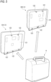
FIG. 5 illustrates a method for manufacturing the vital monitor according to the embodiment. -
FIG. 6 illustrates the method for manufacturing the vital monitor according to the embodiment. -
FIG. 7 illustrates an example of an area VII inFIG. 3 in an enlarged manner. -
FIG. 8 illustrates another example of an area VII inFIG. 3 in an enlarged manner. - Exemplary embodiments will be described in detail below with reference to the accompanying drawings.
- In the accompanying drawings, an arrow F indicates a front direction of the illustrated structure. An arrow B indicates a rear direction of the illustrated structure. An arrow U indicates an upper direction of the illustrated structure. An arrow D indicates a lower direction of the illustrated structure. An arrow R indicates a right direction of the illustrated structure. An arrow L indicates a left direction of the illustrated structure.
-
FIG. 1 illustrates an appearance of a vital monitor 1 according to an embodiment as viewed from the front. The vital monitor 1 is a device that acquires physiological information of a subject through a sensor attached to the subject. The vital monitor 1 is an example of a physiological information acquisition apparatus. - The vital monitor 1 can include a
display device 10. Thedisplay device 10 is a device that displays an image including the acquired physiological information. In this example, thedisplay device 10 can include atouch panel device 101. Thetouch panel device 101 is configured to detect a position to which a finger of a user approaches or touches, so as to receive an instruction from the user corresponding to the position. -
FIG. 2 illustrates an appearance of the vital monitor 1 as viewed from the right rear.FIG. 3 illustrates a cross section taken along a line III-III inFIG. 1 as viewed in a direction of arrows. The vital monitor 1 can include afirst case 11, asecond case 12, and aprocessing device 13. - As illustrated in
FIG. 3 , thefirst case 11 defines aninternal space 111 that accommodates at least theprocessing device 13. Theprocessing device 13 is a device that receives a detection signal corresponding to the physiological information of the subject from the sensor attached to the subject, and acquires the physiological information by performing appropriate processing on the signal. - The
second case 12 supports thedisplay device 10. Thesecond case 12 can include aback wall 121. Theback wall 121 can include afirst portion 121a facing theinternal space 111 defined by thefirst case 11. -
FIG. 4 illustrates an external appearance of thefirst case 11 as viewed from the right front. Illustration of component elements accommodated in theinternal space 111 is omitted. Thefirst case 11 can includecoupling portions 112. - Meanwhile, as illustrated in
FIG. 3 , thesecond case 12 can includecoupling portions 122. Thecoupling portions 122 are disposed at positions, where thecoupling portions 122 can be coupled to thecoupling portions 112 of thefirst case 11, on thefirst portion 121a of theback wall 121. - By coupling the
coupling portions 112 of thefirst case 11 and thecoupling portions 122 of thesecond case 12, a state in which thefirst case 11 and thesecond case 12 are coupled as illustrated inFIG. 2 is obtained. The coupling between thecoupling portions 112 and thecoupling portions 122 may be implemented by engagement or fitting, or may be implemented by screwing via a screw. - As illustrated in
FIG. 5 , thefirst case 11 according to the present embodiment can be commonly coupled to any of a plurality of types ofsecond cases second case 12A and thesecond case 12B are different from each other in size of the screen of the supporteddisplay device 10. That is, dimensions of thesecond case 12A and thesecond case 12B are also different. - On the other hand, the positions of the
coupling portions 122 provided on theback wall 121 of thesecond case 12 are determined such that thecoupling portions 122 can be coupled to thecoupling portions 112 provided on thefirst case 11 regardless of the dimensions of thesecond case 12. Therefore, regardless of whether thesecond case 12A or thesecond case 12B is selected, theinternal space 111, thecoupling portions 112, theback wall 121, and thecoupling portions 122 have a positional relationship illustrated inFIG. 4 . - Therefore, according to a manufacturing method illustrated in
FIG. 6 , it is possible to obtain a plurality of types of vital monitors 1 in which screen sizes of thedisplay devices 10 are different while using thefirst case 11 having a single specification. - Specifically, first, a common
first case 11 is prepared (STEP 1). Subsequently, various component elements including theprocessing device 13 are accommodated in theinternal space 111 of the first case 11 (STEP 2). - On the other hand, a plurality of types of
display devices 10 including different sizes of screens on which the images showing the physiological information are displayed are prepared. Same or similarly, a plurality of types ofsecond cases 12 each for supporting a corresponding type ofdisplay device 10 among the plurality of types ofdisplay devices 10 are prepared. - Subsequently, one type of
display device 10 is selected from the plurality of types ofdisplay devices 10 according to a type of the vital monitor 1 to be manufactured (STEP 3). Same or similarly, one type ofsecond case 12 corresponding to the selected type ofdisplay device 10 is selected from the plurality of types of second cases 12 (STEP 4). - Subsequently, the
coupling portions 112 of the commonfirst case 11 are coupled to thecoupling portions 122 of the selected type ofsecond case 12. Accordingly, thefirst case 11 and thefirst case 12 are coupled such that thefirst portion 121a of theback wall 121 of the selected type ofsecond case 12 faces theinternal space 111 of the common first case 11 (STEP 5). - According to the configuration described above, even when it is necessary to prepare a plurality of types of
second cases 12 in order to support thedisplay devices 10 having different screen sizes according to diversified needs, it is not necessary to prepare a plurality of types offirst cases 11 having different specifications so as to correspond to the plurality of types ofsecond cases 12. It is significant to eliminate the necessity of preparing a plurality of types of dies in order to manufacture thefirst case 11, for example, for efficiency. Therefore, an increase in the number of dies due to an increase in the number of types of the vital monitors 1 can be prevented. - As long as the
processing device 13 is finally accommodated in theinternal space 111 by coupling thefirst case 11 and thesecond case 12, the order of the processing illustrated inFIG. 6 may be appropriately changed. For example, instead of the step of accommodating theprocessing device 13 in theinternal space 111 in STEP 2, theprocessing device 13 may be coupled to thefirst portion 121a of theback wall 121 of thesecond case 12 selected in STEP 4. -
FIG. 7 illustrates an example of an enlarged view of an upper end portion of thedisplay device 10 and an upper end portion of thesecond case 12 which are included in a region VII inFIG. 3 . That is, the vital monitor 1 includes aframe member 14 and anelastic member 15. - The
frame member 14 supports thedisplay device 10. Theframe member 14 can include acoupling portion 14a. Thecoupling portion 14a is coupled to thesecond case 12. Thus, theframe member 14 is supported by thesecond case 12. Theframe member 14 can include aback portion 14b facing asecond portion 121b of theback wall 121 of thesecond case 12. Thesecond portion 121b of theback wall 121 is a portion that does not face theinternal space 111 of thefirst case 11. - The
elastic member 15 is formed as an integrally molded product of an elastic material such as rubber or elastomer. Theelastic member 15 can include afirst portion 15a. Thefirst portion 15a of theelastic member 15 is disposed between theback portion 14b of theframe member 14 and thesecond portion 121b of theback wall 121. - Although not illustrated, the same structure is provided over an entire peripheral portion of the
display device 10 and an entire peripheral portion of thesecond case 12. - According to such a configuration, the
first portion 15a of theelastic member 15 can function as a buffer member, and can restrain not only external forces in an upper-lower direction and a left-right direction of thedisplay device 10 but also an external force transmitted from thesecond case 12 side to thedisplay device 10. In particular, in the present embodiment, when a plurality of types ofsecond cases 12 having different dimensions are coupled to the commonfirst case 11, thesecond portion 121b that does not face theinternal space 111 is generated in theback wall 121. Since thefirst portion 15a of theelastic member 15 is disposed at a position facing thesecond portion 121b which is more likely to be exposed to an external force as compared with thefirst portion 121a facing theinternal space 111, the effectiveness of the buffer function described above can be improved. - The
elastic member 15 can include asecond portion 15b. Thefirst portion 15a and thesecond portion 15b are separate portions of theelastic member 15 which is an integrally molded product. Thesecond portion 15b is disposed between thedisplay device 10 and thesecond case 12. Although not illustrated, the same relationship is established over the entire peripheral portion of thedisplay device 10 and the entire peripheral portion of thesecond case 12. - According to such a configuration, a sealing function of preventing liquid or dust from entering the vital monitor 1 from between the
display device 10 and thesecond case 12 can be added to theelastic member 15 having the above-described buffer function. -
FIG. 8 illustrates another example of an enlarged view of an upper end portion of thedisplay device 10 and an upper end portion of thesecond case 12 which are included in a region VII inFIG. 3 .FIG. 8 differs fromFIG. 7 in that thesecond portion 15b of theelastic member 15 has abump portion 15c protruding from thesecond portion 15b. Thebump portion 15c engages with a dent portion of the peripheral portion of thedisplay device 10, and it makes it possible to fix thedisplay device 10 stably. A shape of thebump portion 15c is not limited to a shape illustrated inFIG. 8 . The number ofbump portions 15c may be one or more. - The formation of the
bump portion 15c reduces a contact area between theelastic member 15 and the peripheral portion of thedisplay device 10 compared to a case where thebump portion 15c is not provided, and the interfacial pressure between theelastic member 15 and thedisplay device 10 increases. Therefore, the interfacial pressure of the area where theelastic member 15 contacts with thedisplay device 10 is increased, and it is possible to enhance the waterproof effect of theelastic member 15. - Moreover, the formation of the
bump portion 15c cancels the decrease in interfacial pressure at the portion where thebump portion 15c contacts with thedisplay device 10, even if there is a variation in dimensional tolerance of an opening of the manufacturedsecond case 12. Therefore, contact between thebump portion 15c and the periphery of thedisplay device 10 can be ensured, and it is possible to make the waterproof effect of theelastic member 15 higher compared to the case where thebump portion 15c is not provided. - The above embodiment is merely an example for facilitating the understanding of the presently disclosed subject matter. The configuration according to the above embodiment can be appropriately changed or improved without departing from the gist of the presently disclosed subject matter.
- In
FIG. 5 , only two types ofsecond cases 12 having different dimensions are illustrated. However, it is needless to say that three or more types ofsecond cases 12 may be prepared according to the screen size of thedisplay device 10 to be supported.
Claims (4)
- A method for manufacturing a physiological information acquisition apparatus configured to acquire physiological information of a subject, the method comprising:preparing a common first case that defines an internal space in which a processing device configured to perform processing of acquiring the physiological information is accommodated;preparing a plurality of types of display devices including different sizes of screens for displaying an image including the physiological information;preparing a plurality of types of second cases each for supporting a corresponding type of display device among the plurality of types of display devices;selecting one type of display device from the plurality of types of display devices;selecting, from the plurality of types of second cases, one type of second case corresponding to the selected one type of display device; andcoupling the first case to a coupling portion provided on a back wall of the second case, wherein the back wall faces the internal space.
- A physiological information acquisition apparatus configured to acquire physiological information of a subject, comprising:a processing device configured to perform processing of acquiring the physiological information;a display device configured to display an image including the physiological information;a first case that defines an internal space for accommodating the processing device; anda second case configured to support the display device, whereinthe second case includea back wall facing the internal space, anda coupling portion provided on the back wall and coupled to the first case.
- The physiological information acquisition apparatus according to claim 2, further comprising:a frame member that supports the display device and is supported by the second case; andan elastic member including a portion disposed between the back wall and a portion of the frame member facing the back wall.
- The physiological information acquisition apparatus according to claim 3, wherein
the elastic member includes a portion disposed between the display device and the second case.
Applications Claiming Priority (1)
| Application Number | Priority Date | Filing Date | Title |
|---|---|---|---|
| JP2021125500A JP7670574B2 (en) | 2021-07-30 | 2021-07-30 | Manufacturing method of biological information acquisition device, and biological information acquisition device |
Publications (1)
| Publication Number | Publication Date |
|---|---|
| EP4124286A1 true EP4124286A1 (en) | 2023-02-01 |
Family
ID=82656791
Family Applications (1)
| Application Number | Title | Priority Date | Filing Date |
|---|---|---|---|
| EP22186225.3A Pending EP4124286A1 (en) | 2021-07-30 | 2022-07-21 | Method for manufacturing physiological information acquisition apparatus and physiological information acquisition apparatus |
Country Status (3)
| Country | Link |
|---|---|
| EP (1) | EP4124286A1 (en) |
| JP (1) | JP7670574B2 (en) |
| CN (1) | CN115670378A (en) |
Cited By (1)
| Publication number | Priority date | Publication date | Assignee | Title |
|---|---|---|---|---|
| CN114948248A (en) * | 2018-01-31 | 2022-08-30 | 深圳迈瑞生物医疗电子股份有限公司 | Medical equipment and monitor and medical article containing box thereof |
Citations (4)
| Publication number | Priority date | Publication date | Assignee | Title |
|---|---|---|---|---|
| WO2001086575A2 (en) * | 2000-05-05 | 2001-11-15 | Hill-Rom Services, Inc. | Patient point of care computer system |
| US20120127103A1 (en) * | 2010-11-19 | 2012-05-24 | Bruce Dean Qualey | Configurable patient monitoring system |
| WO2020087453A1 (en) | 2018-11-01 | 2020-05-07 | 深圳迈瑞生物医疗电子股份有限公司 | Monitoring instrument |
| US20200360102A1 (en) * | 2018-01-31 | 2020-11-19 | Shenzhen Mindray Bio-Medical Electronics Co., Ltd. | Medical device and storage box for medical article |
Family Cites Families (1)
| Publication number | Priority date | Publication date | Assignee | Title |
|---|---|---|---|---|
| JP2018042965A (en) * | 2016-09-15 | 2018-03-22 | 株式会社アリス | Biological information monitor having function other than biological information display at separable display part including computer |
-
2021
- 2021-07-30 JP JP2021125500A patent/JP7670574B2/en active Active
-
2022
- 2022-07-21 EP EP22186225.3A patent/EP4124286A1/en active Pending
- 2022-07-22 CN CN202210867381.8A patent/CN115670378A/en active Pending
Patent Citations (5)
| Publication number | Priority date | Publication date | Assignee | Title |
|---|---|---|---|---|
| WO2001086575A2 (en) * | 2000-05-05 | 2001-11-15 | Hill-Rom Services, Inc. | Patient point of care computer system |
| US20120127103A1 (en) * | 2010-11-19 | 2012-05-24 | Bruce Dean Qualey | Configurable patient monitoring system |
| WO2012068564A2 (en) * | 2010-11-19 | 2012-05-24 | Spacelabs Healthcare, Llc | Configurable patient monitoring system |
| US20200360102A1 (en) * | 2018-01-31 | 2020-11-19 | Shenzhen Mindray Bio-Medical Electronics Co., Ltd. | Medical device and storage box for medical article |
| WO2020087453A1 (en) | 2018-11-01 | 2020-05-07 | 深圳迈瑞生物医疗电子股份有限公司 | Monitoring instrument |
Cited By (1)
| Publication number | Priority date | Publication date | Assignee | Title |
|---|---|---|---|---|
| CN114948248A (en) * | 2018-01-31 | 2022-08-30 | 深圳迈瑞生物医疗电子股份有限公司 | Medical equipment and monitor and medical article containing box thereof |
Also Published As
| Publication number | Publication date |
|---|---|
| JP7670574B2 (en) | 2025-04-30 |
| CN115670378A (en) | 2023-02-03 |
| JP2023020240A (en) | 2023-02-09 |
Similar Documents
| Publication | Publication Date | Title |
|---|---|---|
| EP3232258B1 (en) | Multi-face display device | |
| CN108617116B (en) | electronic device | |
| US9166337B2 (en) | Externally latching I/O housing | |
| US6185110B1 (en) | Mounting frame for mounting input/output device to conpactPCI-based computer | |
| JP7213326B2 (en) | Semiconductor devices, display devices, in-vehicle display systems | |
| US9568756B2 (en) | Display device | |
| JP7670574B2 (en) | Manufacturing method of biological information acquisition device, and biological information acquisition device | |
| CN103677122B (en) | Display device, electronic information plate and electronic equipment | |
| US20130176671A1 (en) | Input receiver and electronic device | |
| US20090160791A1 (en) | Non-contact touch screen | |
| JP5063526B2 (en) | Information processing method, program, and information processing apparatus | |
| US20140002755A1 (en) | Video display device | |
| US9106013B2 (en) | Externally latching I/O cable | |
| EP4445239A1 (en) | Display for wearable computing devices having a three-dimensional cover | |
| CN108898956B (en) | Display screen and electronic equipment | |
| JP4410710B2 (en) | Multi display device | |
| KR101114733B1 (en) | Game machine input device | |
| CN201194045Y (en) | Binocular near-eye micro display | |
| KR20160000278U (en) | Fixing bracket and communication terminal including the same | |
| CN215458155U (en) | Ultrasound device | |
| JP7065418B2 (en) | Display device and array base | |
| CN121332237A (en) | PDU power supply and its installation method | |
| KR102341141B1 (en) | Display apparatus | |
| US20100134502A1 (en) | Display method and viewing device making it possible to protect the screen against freezing of the image | |
| JP2023180014A (en) | Push button structure of ultrasound diagnostic equipment |
Legal Events
| Date | Code | Title | Description |
|---|---|---|---|
| PUAI | Public reference made under article 153(3) epc to a published international application that has entered the european phase |
Free format text: ORIGINAL CODE: 0009012 |
|
| STAA | Information on the status of an ep patent application or granted ep patent |
Free format text: STATUS: REQUEST FOR EXAMINATION WAS MADE |
|
| 17P | Request for examination filed |
Effective date: 20220721 |
|
| AK | Designated contracting states |
Kind code of ref document: A1 Designated state(s): AL AT BE BG CH CY CZ DE DK EE ES FI FR GB GR HR HU IE IS IT LI LT LU LV MC MK MT NL NO PL PT RO RS SE SI SK SM TR |
|
| STAA | Information on the status of an ep patent application or granted ep patent |
Free format text: STATUS: EXAMINATION IS IN PROGRESS |
|
| 17Q | First examination report despatched |
Effective date: 20250630 |